Abstract
This paper proposes a new topology for a battery management system (BMS) with active cell balancing capable of exchanging energy between an electric vehicle’s traction and auxiliary batteries. This topology facilitates energy exchange between any cell in the traction battery pack and with the auxiliary battery. The proposed topology allows both the selection of the cells involved in the balancing process and the charging of the auxiliary battery, eliminating the need for a dedicated dc-dc isolated power converter. The flexibility of this topology allows the adoption of different balancing strategies, which can be used to improve balancing efficiency. The proposed topology was first analyzed through computer simulations, and a laboratory BMS prototype was developed. The results from the simulation and experimental tests validate the topology operation and its performance in transferring energy between the cells and the auxiliary battery.
1. Introduction
Electric vehicles (EVs) are considered one of the leading technologies needed to reduce the environmental impact of the transportation sector [1]. Nowadays, several fully electric vehicles are under development, from light vehicles to cars and heavy vehicles, with several hundred models already commercially available [2]. Regarding aircraft, electrification is at an earlier stage, but it is expected to follow the same trend as land vehicles [3].
One of the most critical EV components is the energy storage and management system, which requires high capacity, low weight, compactness, and effective thermal management [4]. EV energy is generally stored in a battery pack containing several elementary cells connected in and/or parallel. To ensure that the cells operate safely and efficiently, they are usually equipped with a supervisory electronic circuit known as a battery management system (BMS) [5]. A BMS should perform monitoring and protection functions, contributing to the integrity and longevity of the cells. To achieve this, it is necessary to measure parameters, such as voltage, current, and operating temperature, to estimate parameters, such as the state of charge (SoC), depth of discharge (DoD), state of health (SoH), and internal resistance [6].
The determination of the SoC is one of the key challenges when dealing with batteries, as discussed in [7]. This is because the methods available for estimating the SoC only approximate this value. The accuracy of SoC estimation can vary significantly depending on the type of battery and the available processing power. The most common methods for estimating the SoC are [8]: open circuit voltage-based methods (OCVMs); Coulomb counting (Ah Counting); resistance spectroscopy-based methods (ISBMs); model-based methods (MBMs); and artificial neural network-based methods (ANNBMs). OCVMs are simple to apply, relying on a predefined relationship between the open circuit voltage (OCV) and the SoC. However, during the operation of most batteries, this relationship can change with temperature and battery deterioration, making the estimation more challenging. To obtain more accurate results, in the case of lithium cells, as described in [8], the battery must be disconnected from the circuit and left to rest during its relaxation time, enabling the OCV to stabilize.
Another relevant feature of the BMS is ensuring the balancing of the battery cells’ charge. Due to slight differences in construction and internal parameters, which increase with charge–discharge cycles and battery lifetime, the energy storage capacity may differ from cell to cell. These differences cause imbalances between the SoC of the cells during normal battery use. Some cells achieve a higher SoC than others, and when a cell with a lower SoC reaches its minimum voltage threshold, the battery stops supplying power even if the remaining cells still have energy to prevent damaging the cell with the lowest SoC [9]. This results in lower battery autonomy, as there is still energy in the battery, but it cannot be used because the cell has reached the minimum voltage limit. On the other hand, during charging, the cells that retained some energy during discharge will charge faster than those that were more discharged, preventing these cells from reaching 100% SoC, thereby creating a cyclical imbalance that exacerbates the issue.
To mitigate this problem, it is necessary to balance the cells to ensure they maintain an equal charge level, thus maximizing battery autonomy [10]. However, the potential of cell balancing has not been well explored, as most BMSs on the market use passive balancing techniques based on dissipating excess energy from the most charged cells through a resistor until they reach the same SoC as the lowest SoC cell [11]. Dissipating energy from the highest SoC cells through resistors is an inefficient and wasteful method of balancing the cells, highlighting the need and opportunity to improve BMSs, particularly regarding balancing circuits [12].
Concerning the research on active balancing circuits for battery cells, the topologies are usually classified according to the main element used in the energy transfer as inductor-based, capacitor-based, and transformer-based topologies [6].
Regarding inductor-based topologies, in [13], the authors propose a balancing circuit where the inductor is the main energy storage element. The circuit, composed of six switches, four capacitors, and three inductors, allows the balance of four cells in a series configuration. An active balancing circuit based on a switched-inductor buck-boost converter with the ability to balance non-adjacent cells is presented in [14]. For a module with three cells in series, the circuit uses two inductors and four switches. In [15], a two-stage active cell-balancing circuit based on a buck-boost converter is proposed. It uses modules consisting of three cells, two inductors, and four MOSFET switches, allowing module-to-module balancing in the first stage and balancing between two cells in a module in the second stage. The authors of [16] propose a new active flying inductor balancing circuit that enables direct energy transfer between any two cells, requiring only one inductor as an intermediate storage element. In [17], the authors propose a new chain-structured cell-balancing circuit using coupled-inductor-based modules achieving high cell-balancing speed.
In terms of capacitor-based topologies, the authors of [18] propose a novel switched-capacitor cell-balancing circuit with a resonant design, allowing all switches employed in the balancing circuit to operate under zero-current switching, thus improving efficiency and performance. The work in [19] proposes an active balancing circuit with two operating modes: any cell to any cell (AC2AC) and direct cell to cell (DC2C). The AC2AC mode is equivalent to a switched capacitor (SC), and the energy is transferred among all imbalanced cells. The DC2C mode is equivalent to a three-resonant-state LC unit, allowing energy transfer from the highest voltage cell to the lowest voltage one.
Transformer-based topologies, also known as isolated topologies, use transformers as the main element in energy transfer. The work in [20] proposes an enhanced switching pattern for an active balancing circuit based on a multi-winding transformer. The circuit, operated in flyback and buck-boost modes, allows the transfer of energy between arbitrary cells. The authors of [21] propose a near-field coupling wireless active cell balancing circuit using planar coupled inductors for high-capacity and high-power battery applications. The work in [22] proposes a novel active cell balancer that supports bidirectional cell balancing operation with very high efficiency, based on an isolated bidirectional dc-dc converter-based active cell balancer. A robust and scalable active battery management system is proposed in [23]. The circuit uses an isolation transformer with two diodes connected to each cell in the battery stack, enabling both accurate cell voltage monitoring and active cell balancing. A cell-to-cell balancing circuit with a bidirectional flyback converter is proposed in [24]. The primary side of the bidirectional flyback converter is connected to the battery pack, and the secondary side is connected to each cell, allowing it to discharge the cell with the highest voltage and charge the cell with the lowest voltage simultaneously.
This paper proposes a new BMS topology for actively balancing battery cells. Unlike other BMSs in the literature, the proposed topology allows the exchange of energy between any cell in the pack as well as with the auxiliary battery of the EV. The main contributions of the proposed BMS topology are:
- Direct energy transfer from the highest SoC to the lowest SoC cell without the involvement of the remaining battery cells.
- Ability to transfer energy between different combinations of cell pairs. For example, at a given moment, n highest SoC cells can transfer energy to m lowest SoC cells ().
- Capability to transfer energy between the cells and the auxiliary battery, ensuring it remains charged. It allows, for instance, that only the highest SoC cells contribute to the auxiliary battery, the number of involved cells increasing or decreasing based on demand.
- Option of transferring energy from the service battery to the cells. While this functionality may not be relevant in EVs, it could be useful in other contexts.
All these features significantly contribute to more efficient balancing, opening the possibility of applying different balancing strategies that can be optimized based on the initial SoC or vehicle behavior history, allowing for improved battery autonomy.
This work is organized as follows: Section 1 introduces BMS technology and reviews the literature. Section 2 presents the proposed topology and describes its working principle and functionalities. Section 3 presents a simulation analysis of the proposed topology. Section 4 presents and discusses the experimental results obtained with a small-scale developed prototype implementing the proposed topology. Finally, Section 5 presents the main achievements and conclusions of the work.
2. New BMS Topology
BMS balancing circuits can be classified into two groups: passive balancing and active balancing. Passive balancing circuits are easy and simple to implement; however, they are inefficient in terms of energy conservation. These circuits consist of connecting a resistor in parallel with the highest SoC cells, a topology known as fixed resistor balancing, or switching a resistor in parallel with the highest SoC cells, which allows better control on the dissipated power, a topology known as switched resistor balancing.
Regarding active balancing, which consists of transferring energy from cells with a larger SoC to cells with a smaller SoC, the number of available topologies is very large, with several of them having been discussed in Section 1. Figure 1 clearly demonstrates the energy benefits that can come from active balancing compared to passive balancing. In this illustrative figure, a reduced number of cells are used to highlight the superiority of active balancing over passive balancing. The initial SoC of the cells is: Cell A 20%, Cell B 60%, Cell A 80%, and Cell A 80%. As can be seen, by applying passive balancing, the final SoC of the cells is 20%, whereas by applying active balancing, the final SoC is 60%, which is a significant difference.
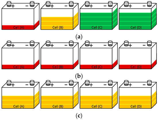
Figure 1.
Passive versus active balancing: (a) Initial SoC before balancing; (b) SoC after passive balancing; (c) SoC after active balancing.
Observing Figure 1, it is intuitive to conclude that the strategy for obtaining more efficient balancing consists of transferring 20% SoC from cells C and D to cell A, keeping cell B unchanged. However, most active balancing circuits only allow the exchange of energy between neighboring cells, making it impossible to implement the most efficient balancing strategy. Thus, for the situation presented in Figure 1, balancing would involve transferring energy from cell B to A, from cell C to B, and finally, from cell D to C, repeating the process until all cells have the same SoC. This involves a high set of energy conversions, causing part of the energy that can be used to be wasted during the conversions carried out until balancing is complete. This limitation ends up being a disadvantage of these simpler active balancing topologies.
The proposed topology aims to overcome these limitations by creating a common dc-bus that allows for, at any time, the ability to define which batteries are involved in the balancing process and control the energy flow between them. In electric vehicle applications, the common bus can be connected to the auxiliary battery, greatly improving system functionality. In other applications, the bus can be connected to one of the cells, maintaining the main functionalities. It is important to note that for all cells to be able to exchange energy with the bus, a galvanically isolated bidirectional dc-dc converter is required.
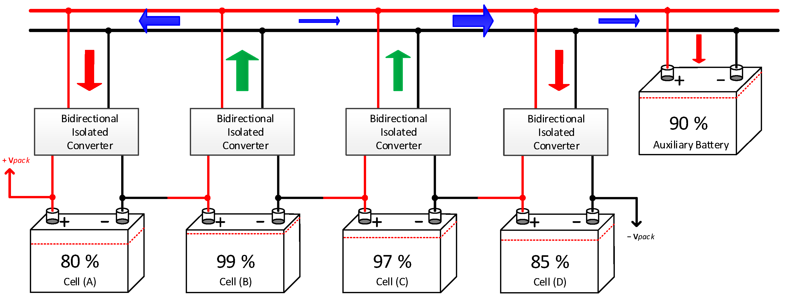
Figure 2 presents a block diagram illustrating the proposed BMS topology and a possible active balancing strategy based on the initial SoC of the cells. In the figure, the arrows represent the energy flow in each point of the circuit, with their thickness proportional to the energy transfer rate (active power). As shown, the cells are connected in series and isolated from the dc-bus and auxiliary battery through bidirectional isolated dc-dc converters. This configuration allows each cell at each instant to inject or absorb energy from the dc-bus independently. The energy in the auxiliary battery is not directly controlled but can be regulated indirectly by operation of each cell’s converter. When the total power injected into the dc-bus exceeds the total power absorbed, the excess energy follows to the auxiliary battery. Conversely, if the power injected equals the power absorbed, there is no energy transfer, i.e., the dc-bus voltage equals the auxiliary battery voltage, and the current is zero, resulting in zero active power. A key advantage of the proposed topology is its ability to charge the auxiliary battery or directly supply the loads connected to it. When the current injected by the cells into the dc-bus matches the load current, the auxiliary battery neither charges nor discharges, maintaining a constant SoC. Furthermore, in this case, balancing a high-voltage cell directly with the auxiliary battery requires only a single energy conversion, being twice as efficient as traditional cell-to-cell balancing, which involves two energy conversions (Cell B to dc-bus and dc-bus to Cell A).
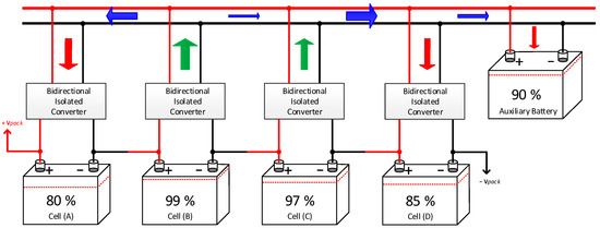
Figure 2.
Illustration of the proposed BMS topology architecture with active cell balancing strategy.
2.1. Dc-Dc Bidirectional Isolated Converter
The isolated dc-dc converter in the proposed BMS topology enables energy transfer between the individual cells and the common dc-bus. For active balancing to be effective, the converter must operate with high efficiency, minimizing losses during energy redistribution. Additionally, it should be compact and inexpensive to maintain the overall size and cost of the BMS acceptable.
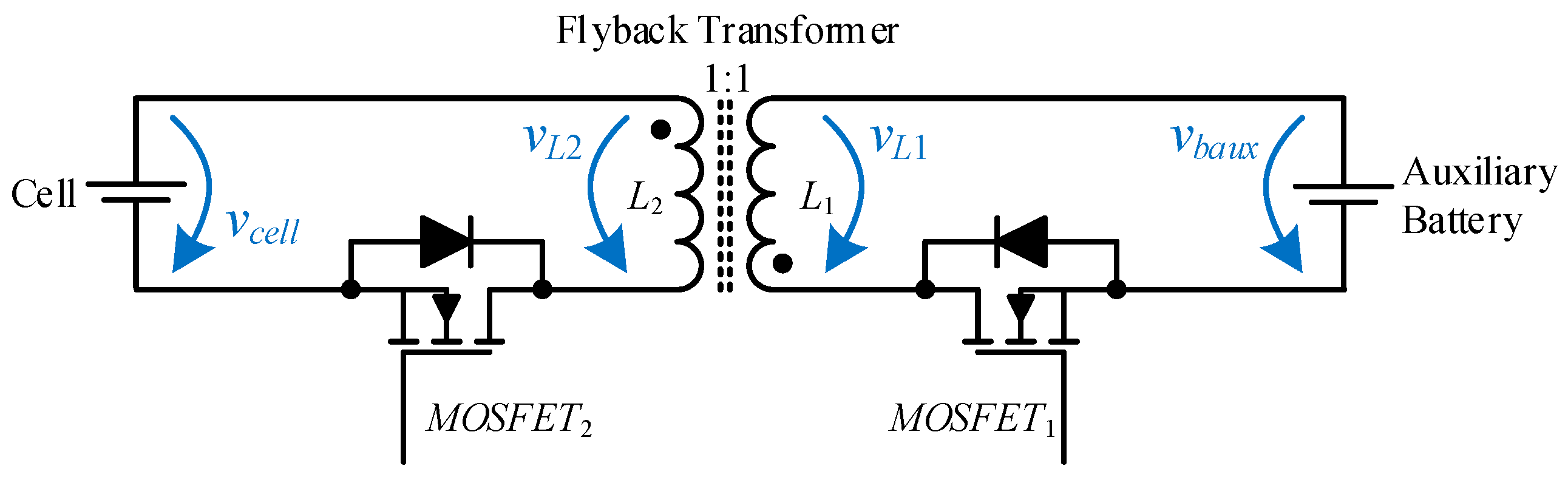
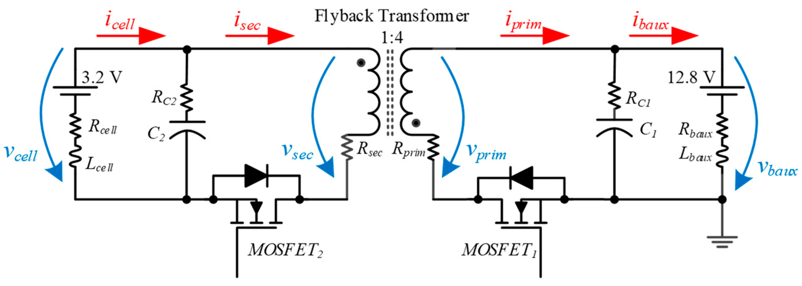
Among the topologies studied, the bidirectional flyback converter was selected due to its simplicity, suitability for the desired power range, and low component count. These features make it particularly attractive for the BMS under development. Figure 3 shows the schematic of the bidirectional flyback converter used in the active cell balancing circuit. As show, the converter consists of a flyback transformer, an electromagnetic element consisting of two isolated inductors sharing the same magnetic core, two MOSFETs with integrated reverse diodes, and two capacitors. In other words, the low component count enables a compact and cost-effective design. It should be noted that the capacitors are not essential; they are only intended to mitigate current spikes in the cells.
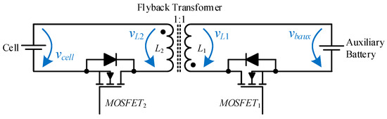
Figure 3.
Bidirectional flyback converter used in the proposed BMS for active cell balancing.
The operation of the bidirectional flyback converter is straightforward. To transfer energy from the cell to the auxiliary battery, a pulse width modulation (PWM) signal must be applied to MOSFET2, while MOSFET1 remains off. The power increases with the duty cycle of the PWM signal. For energy transfer in the opposite direction, the process is reversed, MOSFET2 is turned off, and a PWM signal is applied to MOSFET1.
The converter’s operation is symmetrical, so a more detailed analysis of its operation will only be carried out in the process of transferring energy from the cell to the auxiliary battery, with MOSFET1 always being turned off and only its internal diode intervening in the process. Thus, assuming all components are ideal and a turn ratio of 1:1 in the flyback transformer, the following can be stated:
- MOSFET2 ON (tON)—When MOSFET2 is turned ON, and the inductor current increases at a constant ratio, . Assuming vcell constant during tON, then , and the energy stored in the inductor increases at a constant rate, reaching the final value of . During tON, considering the polarity of the flyback transformer winding, , causing the MOSFET1 diode to be reverse biased, preventing the circulation of current in L1.
- MOSFET2 OFF (tOFF)—When MOSFET2 is turned OFF, the path for current iL2 is interrupted and the L2 inductor voltage instantaneously goes negative . A negative voltage on L2 causes a positive voltage to appear on L1, , directly biasing the diode of MOSFET1, allowing the energy stored in the flyback transformer to flow to the auxiliary battery. During tOFF, the current in L1, which instantly reaches the maximum value, decreases at a constant rate as the energy stored in the transformer decreases.
These two states are repeated, ensuring a continuous flow of energy from the cell to the auxiliary battery. Two scenarios can occur depending on the duty cycle and the frequency of the PWM signal.
Firstly, if all the energy stored in the flyback transformer is discharged into the auxiliary battery and, when MOSFET2 has turned ON again, the current starts from zero, then the converter will be operating in discontinuous mode. In this mode, the converter efficiency will be better, and the stress on the semiconductors will be lower.
Secondly, if energy remains stored in the transformer when MOSFET2 is turned on, the current will increase from an initial value greater than zero, and the converter will operate in continuous mode. In this mode, the power density is higher, but the stress on the semiconductors increases.
2.2. Distributed Architecture
This work aimed to develop a modular BMS topology that is scalable for a large number of cells. Therefore, a distributed architecture based on a master–slave hierarchy was chosen. The design features a master module connected to the auxiliary battery, which performs most of the typical BMS functions, including monitoring the battery pack current and providing features, such as overcurrent protection, Coulomb counting, SoC estimation, and CAN communication with the other EV subsystems. The master is also responsible for monitoring the voltage and temperature of the auxiliary battery, as well as receiving information about the voltage and temperature of each cell through a digital communication bus. For this work, the use of a slave for each cell was implemented, utilizing a RS485 bus communication. The RS485 was chosen to avoid the need for more expensive microcontrollers with built-in CAN peripherals.
Regarding the BMS architecture, many other options could have been considered, such as using a slave module for a set of 4 or 5 cells, using other communication technologies, etc. However, this is not the main focus of this work; the objective was to obtain a flexible and functional BMS topology. Figure 4 shows a simplified schematic of the distributed BMS topology where the master and three slaves are represented.
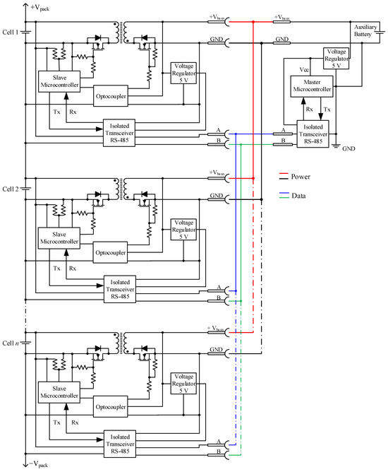
Figure 4.
Simplified schematic of the BMS distributed topology.
The master microcontroller powered by the auxiliary battery is responsible for the entire operation of the system. On the other hand, the slave microcontrollers, powered by the cells, communicate with the master through a galvanically isolated RS485 bus, providing the master with information about the status of the monitored cell and receiving orders to send or receive energy from the balancing circuit.
The PWM signals applied to the converter MOSFETs are generated locally by the slave microcontrollers. During the project, several precautions were taken to ensure the proper operation of the microcontrollers throughout the entire voltage range of the cells. More details on the selected components are presented in Section 4.
The topology proposed in this work allows energy transfer between any cell to any cell through a dc-bus connected to the auxiliary battery of the EV, enabling the energy exchange between the traction battery (high power, high voltage) and the auxiliary battery (low power, low voltage). This flexibility in energy exchange supports a wide range of balancing strategies. The greater the number of cells, the greater the number of balancing combinations. Appendix A presents and describes an example code synopsis for a possible balancing strategy.
3. Simulation of Dc-Dc Bidirectional Isolated Converter
This section presents the results obtained through computer simulations, developed with PSIM 9.1 software, related to the dc-dc bidirectional isolated converter. Nowadays, simulation is an important step in the sizing of power electronics converters and in improving control algorithms. If the converter parameters are modeled accurately and the simulations are conducted properly, the results obtained serve as a good indicator of what the converter’s behavior will be experimentally.
For this work it was defined that the cells to be used would be of lithium iron phosphate (LiFePO4) technology with a 3.2 V nominal voltage, and the auxiliary battery would be of lead-acid technology with a nominal voltage of 12.8 V. It was also defined that the balancing current would range between 0.1 and 1 A.
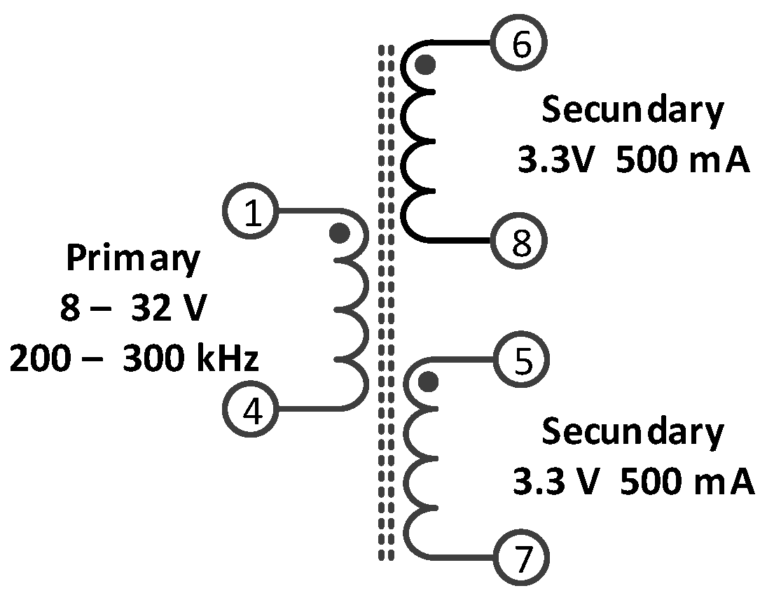
Based on these parameters, a search was carried out for flyback transformers best suited for this application. A transformer with three windings, one primary and two secondaries, was selected: the WE-FLYLT 750313973 from Würth Elektronik (Würth Elektronik eiSos GmbH & Co. KG, Waldenburg, Germany). Figure 5 shows the schematic of the flyback transformer windings arrangement, pinout, and typical operation characteristics. The main electrical specifications of the flyback transformer are presented in Table 1. In this work, the winding N1 is connected to the high-side voltage (auxiliary battery), and the windings N2 and N3 are connected in parallel to the low-side voltage (cell), effectively forming a single winding.
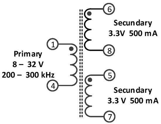
Figure 5.
Flyback transformer windings arrangement and pinout.

Table 1.
Electrical properties of the flyback transformer WE-FLYLT 750313973.
To simulate the flyback transformer, the “coupled inductor” component was used. Considering L11 and L22 as self-inductances of the primary and secondary windings, respectively, and L12 and L21 as the mutual inductances, the voltages and currents in the primary (v1, i1) and secondary (v2, i2) windings are related as follows:
Considering mutual inductances of equal value, i.e., , the transformer coupling factor, k, can be calculated by:
The coupling factor gets a value between 0 and 1. The higher the coupling factor, the better, and in the limit, 1 represents ideal coupling.
The self-inductance values are proportional to the square of the number of turns. Therefore, if N1 is the primary winding turns number and N2 the secondary winding turns number, then the relation between the self-inductances can be obtained by:
Knowing that (from Table 1), L22 will be 2.5 µH, given that the transformer ratio is 4:1. The relation between the primary sell inductance (L11) and the primary leakage inductance () is obtained by (4), where k is the windings coupling factor.
Using , (from Table 1), the coupling factor value of k = 0.975 was obtained. Thus, the value of mutual inductance can be calculated, . The transformer parameters for the simulation are summarized in Table 2.
Table 2.
Flyback transformer simulation parameters.
Figure 6 presents the schematic of the bidirectional flyback converter used in the simulation. Unlike the circuit presented in Figure 3, this circuit accounts for the components’ parasitic elements to achieve more realistic results. Table 3 presents the values of the components used in the simulation model.
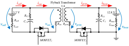
Figure 6.
Schematic of the bidirectional flyback converter used in the simulation.
Table 3.
Simulation parameters.
Analyzing the operation in the energy transfer mode from the cell to the auxiliary battery, MOSFET1 is always OFF, and two different states arise depending on the state of MOSFET2.
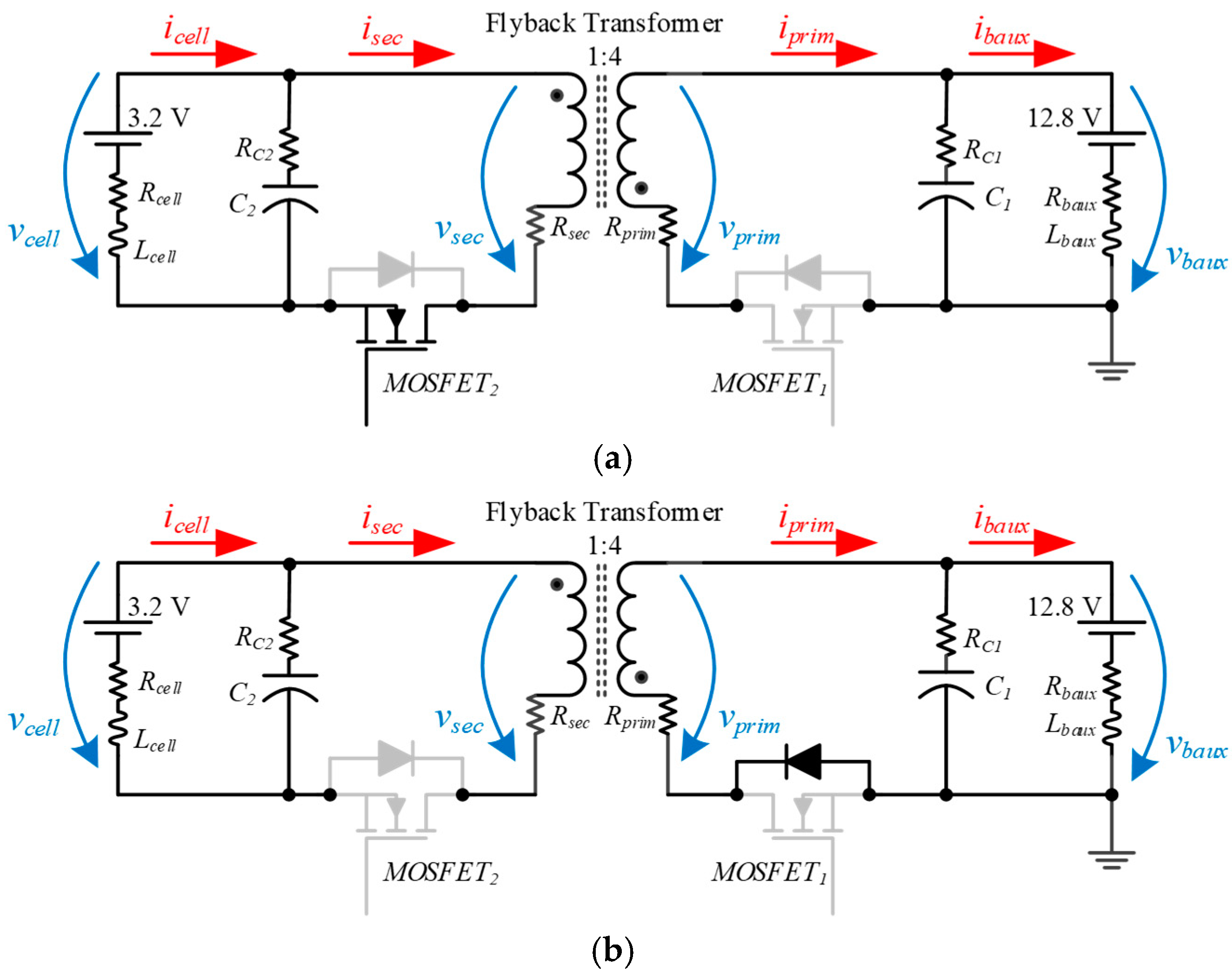
Figure 7 represents the two states mentioned, where Figure 7a shows the components involved in the energy transfer from the cell to the flyback transformer during tON, and Figure 7b shows the components involved in the energy transfer from the flyback transformer to the auxiliary battery during tOFF. Greyed-out components are not used in these states.
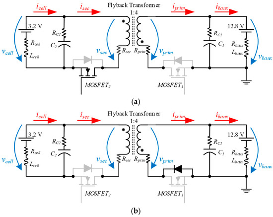
Figure 7.
Bidirectional flyback converter transferring energy from the cell to the auxiliary battery: (a) During tON, when MOSFET2 is ON; (b) During tOFF, when MOSFET2 is OFF.
Figure 8 presents the simulation results of the bidirectional flyback converter transferring energy from the cell to the auxiliary battery. Figure 8a shows the pulse width modulation (PWM) signal of MOSFET2. Figure 8b shows the secondary winding voltage (vsec) when MOSFET2 is ON, vsec is equal to vcell, and vprim is negative with four times more amplitude. When the MOSFET2 is turned OFF, vsec becomes negative with a quarter of the auxiliary battery voltage amplitude, and vprim is positive and equal to the auxiliary battery voltage. The winding voltages become zero when all the energy stored in the transformer is transferred to the auxiliary battery. This demonstrates that the converter operates in discontinuous mode.
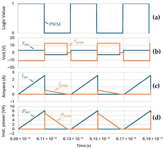
Figure 8.
Simulation results of the bidirectional flyback converter transferring energy from the cell to the auxiliary battery: (a) PWM signal of MOSFET2; (b) Voltages in the transformer secondary and primary windings; (c) Currents in the transformer secondary and primary windings; (d) Instantaneous power in the transformer secondary and primary windings.
Figure 8c shows the secondary and primary currents. When MOSFET2 is turned ON, isec increases at a constant rate, starting from zero. When the MOSFET2 is turned OFF, isec ceases and iprim instantaneously reaches its maximum value before decreasing at a constant rate until zero. The maximum value of isec is four times greater than the maximum value of iprim, due to the transformation ratio.
Figure 8d shows the instantaneous power in the transformer’s secondary and primary windings. The area of the trapezoid, psec, corresponds to the energy transferred from the cell to the flyback transformer. The area of the trapezoid, pprim, corresponds to the energy transferred from the flyback transformer to the auxiliary battery and is positive because of the assumed direction of the auxiliary battery current (see Figure 6).
These results demonstrate the correct operation of the bidirectional flyback transformer transferring energy from the cell to the auxiliary battery. As the converter operates symmetrically, the results of transferring energy from the auxiliary battery to the cell are redundant and are not presented.
4. Experimental Validation of the Dc-Dc Bidirectional Isolated Converter
This section presents the results obtained with the BMS prototype developed using the proposed topology. The experimental setup used to acquire the results consists of three 3.2 V, 100 Ah, LiFePO4 cells connected in series (one per slave module). A 12 V, 45 Ah lead-acid battery was used to emulate the EV’s auxiliary battery. A four-channel Tektronix TPS 2024B oscilloscope (Tektronix, Beaverton, OR, USA) and a Tektronix A6302 current clamp were used to capture the results.
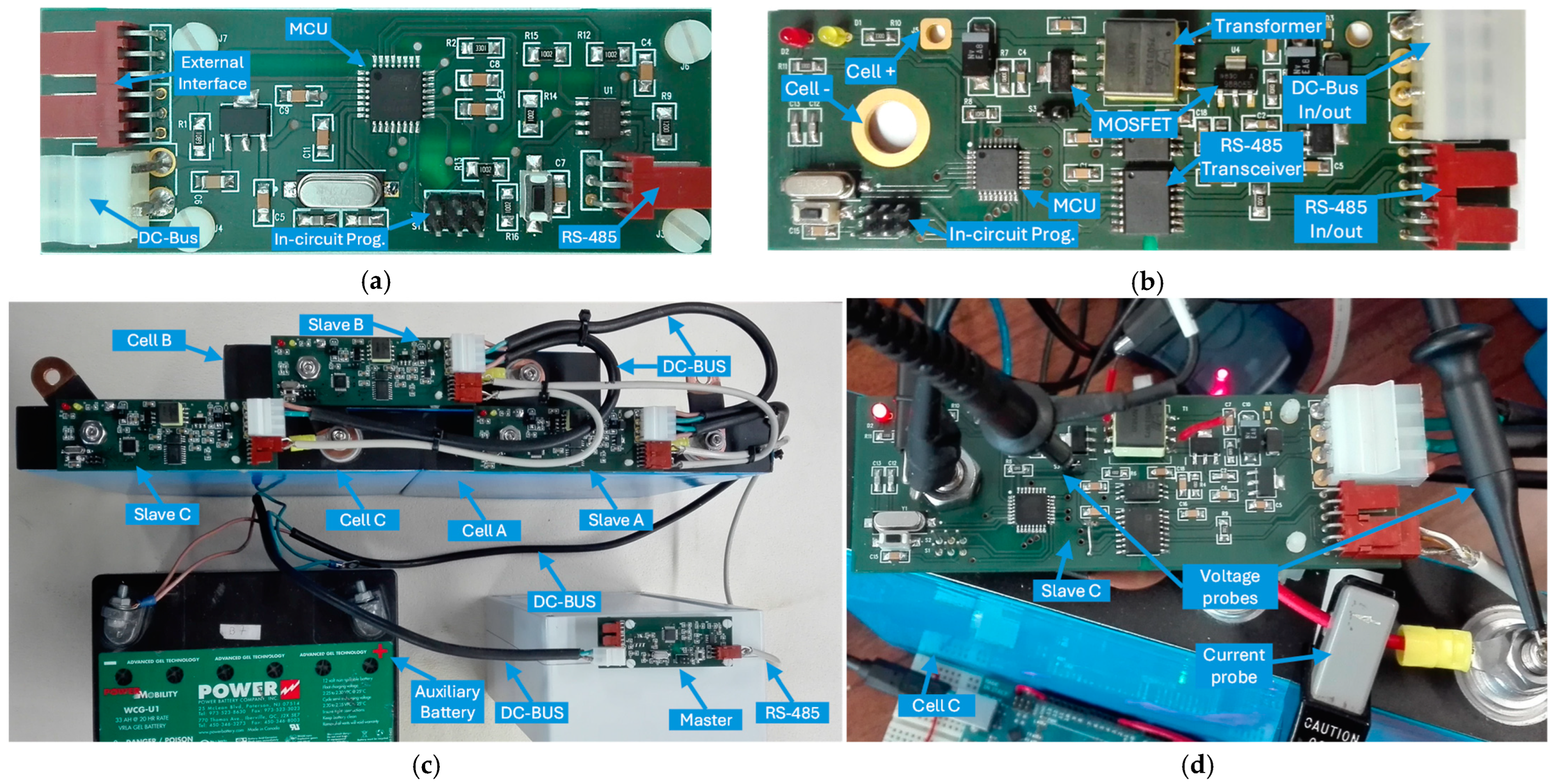
Figure 9 presents the BMS prototype developed for experimental tests. Figure 9a shows the master PCB, Figure 9b shows the slave PCB, Figure 9c shows the prototype assembled with three series of 3.2 V, 100 Ah LiFePO4 cells, and a 12 V lead-acid battery, ready for tests, and Figure 9d shows a detail of current and voltage probes used during experimental tests.

Figure 9.
Developed laboratory prototype of the BMS: (a) Master module; (b) One of the three slave modules; (c) BMS assembled with three cells and auxiliary battery; (d) Detail of current and voltage probes used during experimental results acquisition.
4.1. Energy Transfer from the Cell to the Auxiliary Battery
During energy transfer from the cell to the auxiliary battery, the MOSFET1 is kept OFF, and a PWM signal is applied to MOSFET2. The energy transfer occurs in two steps: during tON, the energy is transferred from the cell to the flyback transformer; during tOFF, the energy is transferred from the flyback transformer to the auxiliary battery.
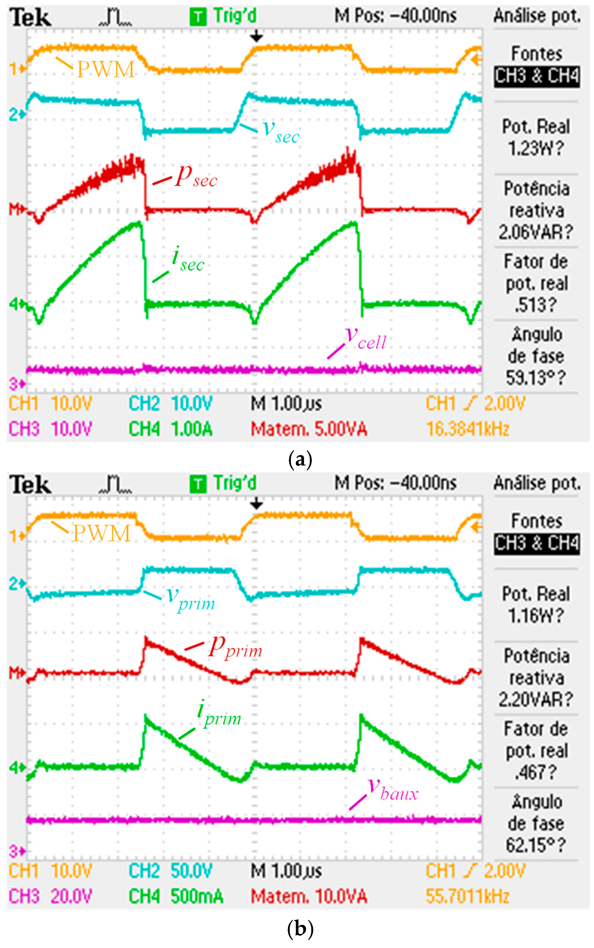
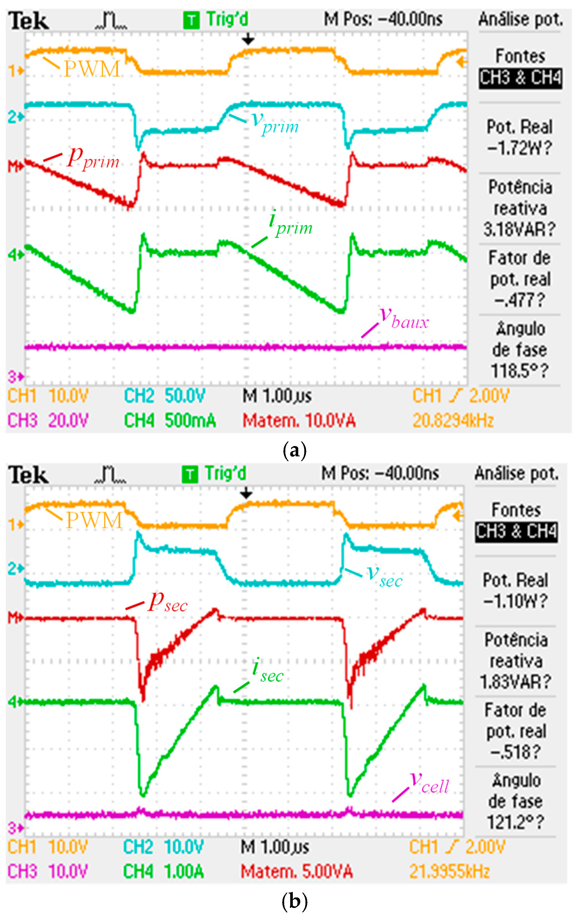
Figure 10 presents experimental results during the energy transfer from the cell to the auxiliary battery. The results in Figure 10a refer to the secondary side of the flyback transformer and show the energy transfer from the cell to the flyback transformer. During tON, the secondary winding voltage (vsec) is equal to the cell voltage (vcell), the secondary current (isec) increases almost linearly, and the instantaneous power (psec) has similar behavior to isec. During tOFF, the secondary winding voltage (vsec) is equal to −¼ of the auxiliary battery voltage (vbaux), the secondary current (isec) is zero, and, as a result, the instantaneous power (psec) is also zero. As expected, the cell voltage (vcell) does not undergo any changes during the two-time intervals.
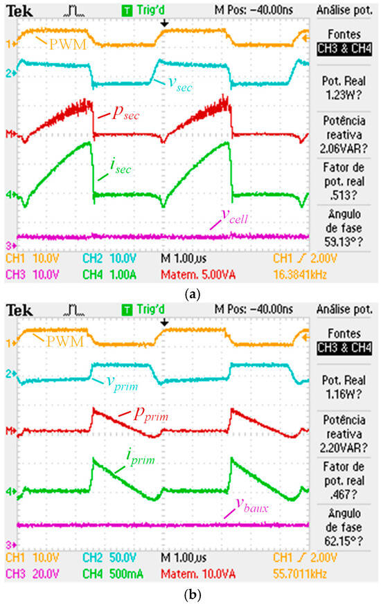
Figure 10.
Experimental results of the BMS prototype transferring energy from the cell to the auxiliary battery: (a) PWM signal applied to MOSFET2, voltage in the secondary winding of flyback transformer, current in the secondary winding of flyback transformer, cell voltage, and instantaneous power in the secondary winding of flyback transformer; (b) PWM signal applied to MOSFET2, voltage in the primary winding of flyback transformer, current in the primary winding of flyback transformer, auxiliary battery voltage, and instantaneous power in the secondary winding of flyback transformer.
The results in Figure 10b refer to the primary side of the flyback transformer and show the energy transfer from the flyback transformer to the auxiliary battery. During tON, the primary winding voltage (vprim) is equal to −4 vcell, the primary current (iprim) is zero, and the instantaneous power (pprim) is also zero. During tOFF, the primary winding voltage (vprim) is equal to the auxiliary battery voltage (vbaux), the primary current (iprim) instantaneously reaches its maximum value and decreases almost linearly, and the instantaneous power (pprim) follows a similar behavior to iprim. As expected, the auxiliary battery voltage (vbaux) does not undergo any changes during the two-time intervals.
The results obtained when transferring energy from the cell to the auxiliary battery correspond to what was expected. The waveforms obtained from both the primary and secondary sides of the flyback transformer are very similar to the simulation results, with only minor differences due to the non-ideal nature of the real electronic components and limitations of the measuring instruments.
4.2. Energy Transfer from the Auxiliary Battery to the Cell
During the energy transfer from the auxiliary battery to the cell, MOSFET2 is kept OFF, and a PWM signal is applied to MOSFET1. The energy transfer occurs in two steps: during tON, the energy is transferred from the auxiliary battery to the flyback transformer; during tOFF, the energy is transferred from the flyback transformer to the cell.
Figure 11 presents the experimental results during the energy transfer from the auxiliary battery to the cell. The results in Figure 11a refer to the primary side of the flyback transformer and show the energy transfer from the auxiliary battery to the flyback transformer. During tON the primary winding voltage (vprim) is equal to the auxiliary battery voltage (vbaux), the primary current (iprim) decreases almost linearly, and the instantaneous power (pprim) has similar behavior to iprim. The reason for obtaining negative values for iprim and pprim is the direction assumed as positive for iprim (see Figure 6).
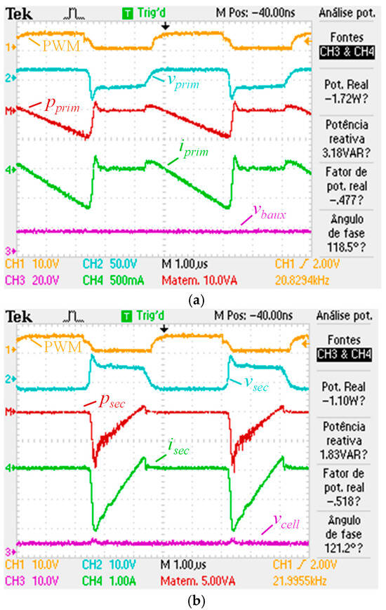
Figure 11.
Experimental results of the BMS prototype transferring energy from the auxiliary battery to the cell: (a) PWM signal applied to MOSFET1, voltage in the primary winding of flyback transformer, current in the primary winding of flyback transformer, auxiliary battery voltage, and instantaneous power in the primary winding of flyback transformer; (b) PWM signal applied to MOSFET1, voltage in the secondary primary of flyback transformer, current in auxiliary battery, auxiliary battery voltage, and instantaneous power in the auxiliary battery.
The results in Figure 11b refer to the secondary side of the flyback transformer and show the energy transfer from the flyback transformer to the auxiliary battery. During tON the secondary winding voltage (vsec) is equal to −¼ vbaux, the secondary current (isec) is zero, and consequently, the instantaneous power (psec) is also zero. During tOFF, the secondary winding voltage (vsec) is equal to vcell, the secondary current (isec) instantaneously decreases until the minimum value and then increases almost linearly until zero, and the instantaneous power (psec) has similar behavior to isec.
As before, the results obtained when transferring energy from the auxiliary battery to the cell align with the expectations. The results in this mode are practically symmetrical to the signals obtained in the previous mode. Once again, the waveforms presented highlight the non-ideal nature of the real electronic components and limitations of the measuring instruments.
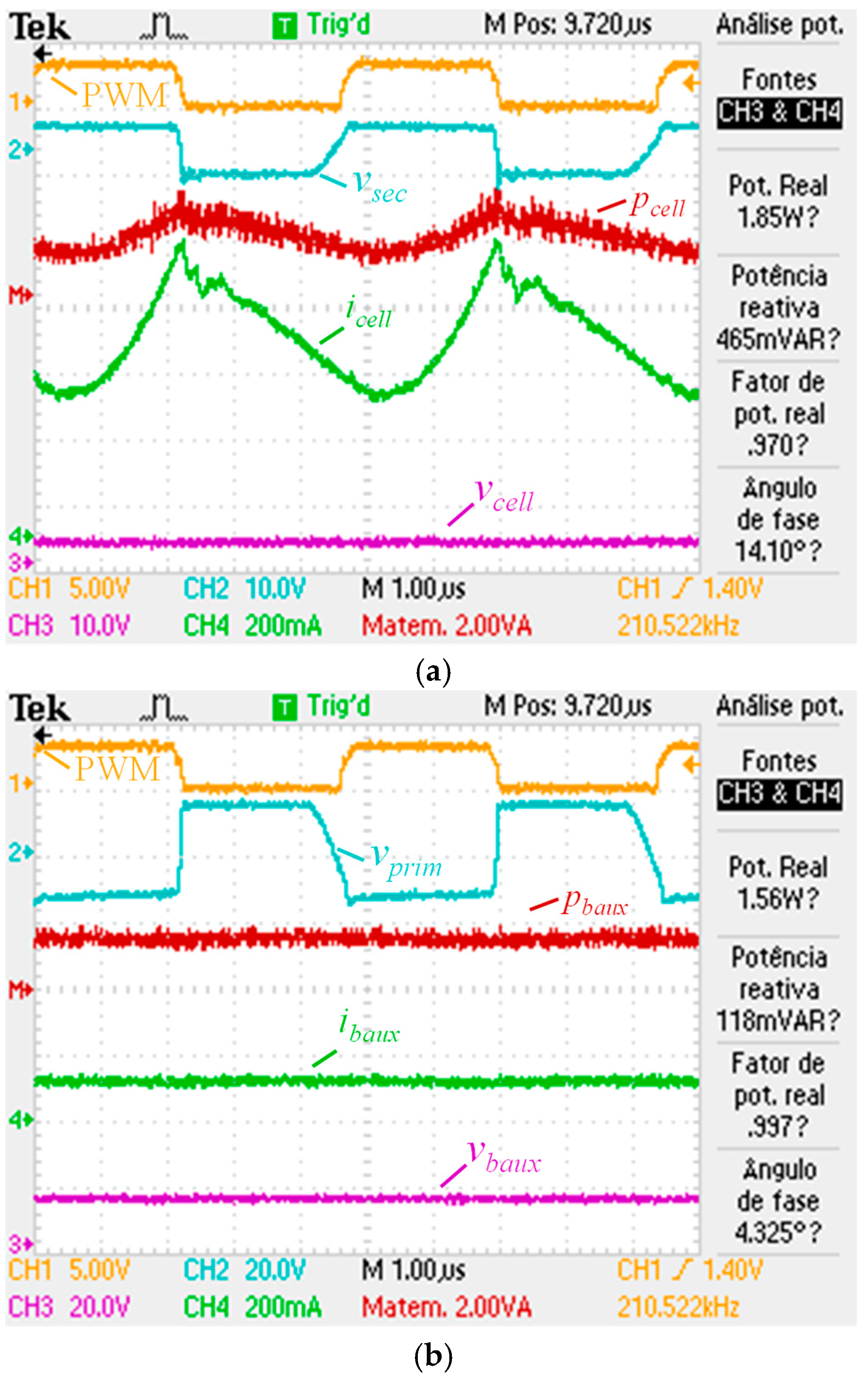
Figure 12 presents experimental results during the energy transfer from the cell to the auxiliary battery to assess power conversion efficiency.
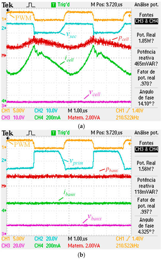
Figure 12.
Experimental results of the BMS prototype transferring energy from the cell to the auxiliary battery: (a) PWM signal applied to MOSFET2, voltage in the primary winding of flyback transformer, current in the cell, cell voltage, and instantaneous in the cell; (b) PWM signal applied to MOSFET2, voltage in the secondary winding of flyback transformer, current in the auxiliary battery, auxiliary battery voltage, and instantaneous power in the auxiliary battery.
The results in Figure 12a refer to the secondary side of the flyback transformer and show the energy transfer from the cell to the flyback transformer. During tON, the secondary winding voltage (vsec) is equal to the cell voltage (vcell), the cell current (icell) increases, and the instantaneous power (psec) has similar behavior to icell. During tOFF, the secondary winding voltage (vsec) is equal to −¼ of the auxiliary battery voltage (vbaux), the secondary current (isec) is zero, but the cell continues to charge the capacitor C2 (Figure 7) and, as a result, the cell current decreases as the capacitor voltage increases. As expected, the cell voltage (vcell) does not undergo any changes during the two-time intervals.
The results in Figure 12b refer to the primary side of the flyback transformer and show the energy transfer from the flyback transformer to the auxiliary battery. During tON, the primary winding voltage (vprim) is equal to −4 vcell. As a consequence of capacitor C2 (Figure 7) and the high impedance of the dc-bus wiring acting as a low-pass filter, the auxiliary battery current (ibaux) is almost constant, and the instantaneous power in the auxiliary battery (pbaux) has similar behavior. As expected, the auxiliary battery voltage (vbaux) does not undergo any changes during the two-time intervals.
Considering the active power measured by the oscilloscope, the efficiency of the power converter can be calculated as 0.843 (1.56/1.85), almost 84%.
The experimental results obtained confirm the flexibility and reliability of the bidirectional flyback converter in transferring energy both from the cell to the auxiliary battery and in the opposite direction, proving to be a valid choice for the distributed BMS architecture with active balancing. The measured power conversion efficiency was quantified as 84%. The authors believe that with an increase in the dc-bus wiring section and some improvements to the circuit such as in the layout, the adoption of an external diode, Schottky type, to be placed in parallel with the internal diodes of the MOSFET1 and MOSFET2, it will be possible to obtain an efficiency greater than 90%. Another aspect to be improved in a new version of the BMS prototype relates to safety and fault protection. The adoption of fuses should be considered in the event of insulation failure in the flyback transformer to isolate the failure. Regarding communications, the use of an optical fiber ring topology, or even a wireless topology, could be considered but at an additional cost. Finally, a technique to enhance the resistance of the circuits against external factors is to immerse them in epoxy resin.
5. Conclusions
This paper proposes a new BMS topology with distributed architecture, active cell balancing, and the capability to exchange energy between any cells in the traction pack and with the EV auxiliary battery. The proposed topology is based on a master/slave architecture where the master module monitors the auxiliary battery, and each of the slave modules monitors one of the pack cells. All the models are connected to a communication bus based on an RS-485 physical layer.
A bidirectional flyback converter was used to transfer energy between each of the pack cells, with a common dc-bus connected to the auxiliary battery, facilitating the exchange of energy between any cell in the traction battery pack and with the auxiliary battery, allowing at each time, the selection of the cells involved in the balancing process, and enabling charging of the auxiliary battery if necessary.
The flexibility of the proposed BMS permits different balancing strategies, improving the balancing efficiency. The active cell balancing circuit was analyzed through computer simulations and tested experimentally in a developed small-scale laboratory prototype. The simulation and experimental results validated the ability of the system to transfer energy between the cells and the auxiliary battery, proving to be a valid architecture for the distributed BMS with active cell balancing. The power conversion efficiency was measured as 84%. Despite the flexibility in energy transfer, the proposed topology presents some limitations and potential disadvantages, such as higher volume, height, and cost, compared to other BMS topologies, namely those with passive balancing.
Author Contributions
Conceptualization, J.G.O.P. and M.F.S.; methodology, J.G.O.P. and M.F.S.; software, M.F.S.; validation, M.F.S., J.G.O.P. and L.A.M.B.; formal analysis, J.G.O.P., M.F.S., L.A.M.B. and J.A.A.; investigation, J.G.O.P. and M.F.S.; resources, J.G.O.P.; data curation, J.G.O.P., M.F.S., L.A.M.B. and J.A.A.; writing—original draft preparation, J.G.O.P.; writing—review and editing, J.G.O.P., M.F.S., L.A.M.B. and J.A.A.; visualization, M.F.S., L.A.M.B. and J.A.A.; supervision, J.G.O.P. All authors have read and agreed to the published version of the manuscript.
Funding
This work has been supported by FCT—Fundação para a Ciência e Tecnologia within the R&D Unit Project Scope UID/00319/Centro ALGORITMI (ALGORITMI/UM).
Data Availability Statement
The original contributions presented in the study are included in the article, further inquiries can be directed to the corresponding authors.
Conflicts of Interest
The authors declare no conflicts of interest.
Abbreviations
The following abbreviations are used in this manuscript:
| BMS | battery management system |
| CAN | controller area network |
| dc | direct current |
| DoD | depth of discharge |
| EV | electric vehicle |
| MOSFET | metal oxide semiconductor field effect transistor |
| PWM | pulse width modulation |
| SoC | state of charge |
| SoH | state of health |
Appendix A
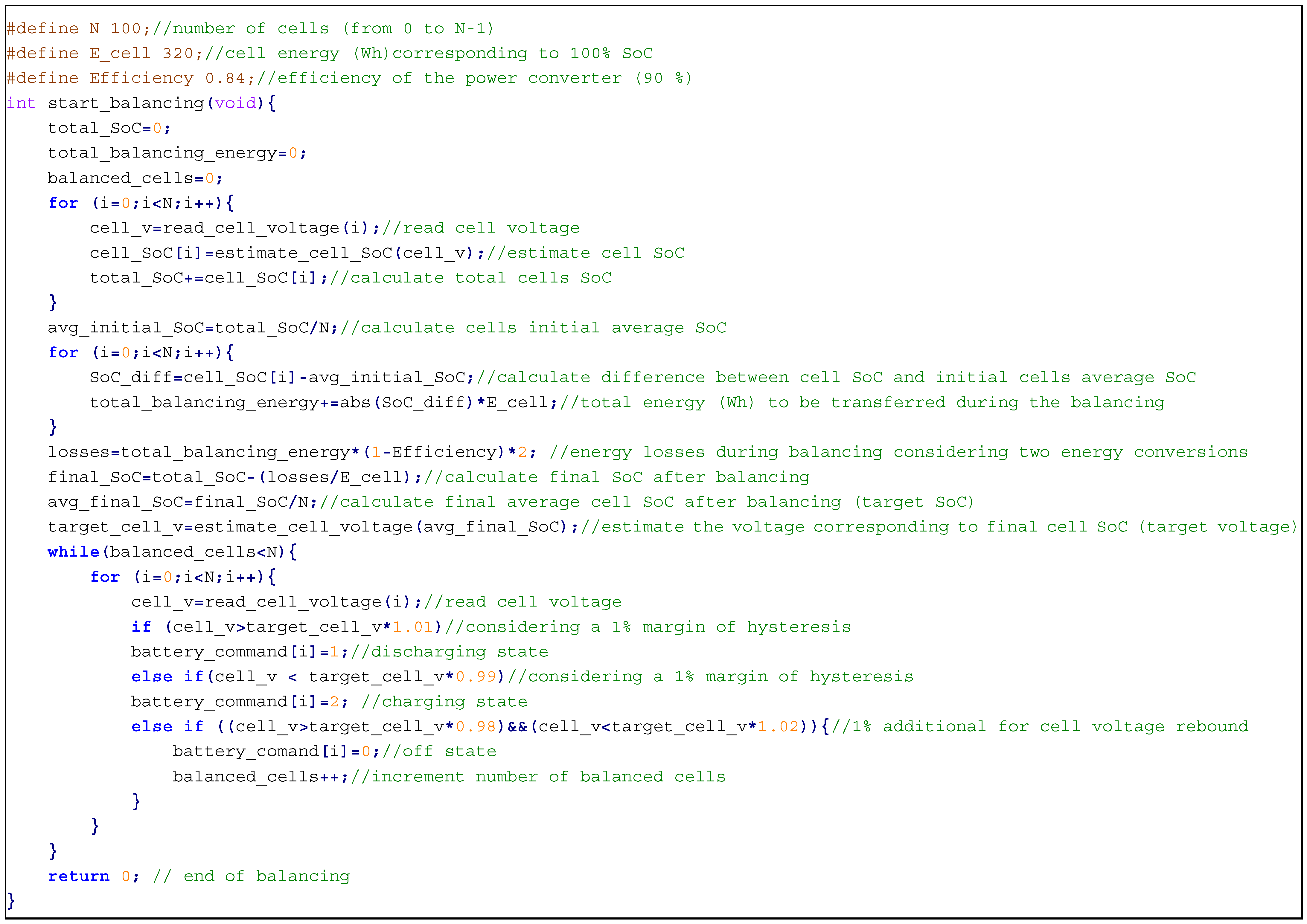
Figure A1 presents an example code synopsis for a balancing strategy applied to a pack of 100 cells, 3.2 V/100 Ah (320 Wh), without involving the auxiliary battery (at the end of balancing, the final energy in the auxiliary battery will be equal to the energy existing at the beginning of balancing) based on OCVM. To implement this strategy, the BMS measures the initial cell voltages to estimate their initial SoC (cell_SoC[i]) and the initial total SoC (total_SoC). Dividing the initial total SoC by the number of cells gives their average initial SoC (avg_initial_SoC). It then calculates the total energy to be transferred during cell balancing (total_balancing_energy). Based on this amount of energy, the algorithm estimates the energy losses in the power converter circuits (losses), considering two power conversions: from the cell B to the dc-bus and from the dc-bus to cell A. The SoC after balancing (final_SoC) will be equal to the initial SoC minus the losses during balancing. Based on the final SoC, it is possible to estimate the cells’ balancing end voltage (target_cell_v). Then, the system enters a balancing loop, ending when all the cells reach the target voltage. A hysteresis of 1% is applied to prevent the cells from entering consecutive charging/discharging states and a hysteresis of 2% is applied to assume the cell as balanced. This value considers the cell voltage rebound and assumes that the cells are balanced within a tolerance range of 2% related to the target voltage.
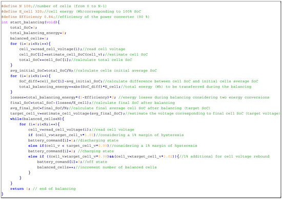
Figure A1.
Example code synopsis of a balancing strategy for the pack cells without involving the auxiliary battery.
Figure A1.
Example code synopsis of a balancing strategy for the pack cells without involving the auxiliary battery.
References
- Tintelecan, A.; Dobra, A.C.; Marţiş, C. LCA Indicators in Electric Vehicles Environmental Impact Assessment. In Proceedings of the 2019 Electric Vehicles International Conference (EV), Bucharest, Romania, 3–4 October 2019; pp. 1–5. [Google Scholar]
- Murali, N.; Mini, V.P.; Ushakumari, S. Electric Vehicle Market Analysis and Trends. In Proceedings of the 2022 IEEE 19th India Council International Conference (INDICON), Kochi, India, 24–26 November 2022; pp. 1–6. [Google Scholar]
- Roboam, X. A Review of Powertrain Electrification for Greener Aircraft. Energies 2023, 16, 6831. [Google Scholar] [CrossRef]
- Kumar, R.R.; Bharatiraja, C.; Udhayakumar, K.; Devakirubakaran, S.; Sekar, K.S.; Mihet-Popa, L. Advances in Batteries, Battery Modeling, Battery Management System, Battery Thermal Management, SOC, SOH, and Charge/Discharge Characteristics in EV Applications. IEEE Access 2023, 11, 105761–105809. [Google Scholar] [CrossRef]
- Vijaychandra, J.; Knypiński, Ł. A Comprehensive Review on Challenges and Possible Solutions of Battery Management Systems in Electric Vehicles. In Proceedings of the 2024 Progress in Applied Electrical Engineering (PAEE), Koscielisko, Poland, 24–28 June 2024; pp. 1–6. [Google Scholar]
- Miranda, J.P.D.; Barros, L.A.M.; Pinto, J.G. A Review on Power Electronic Converters for Modular BMS with Active Balancing. Energies 2023, 16, 3255. [Google Scholar] [CrossRef]
- Li, Z.; Huang, J.; Liaw, B.Y.; Zhang, J. On state-of-charge determination for lithium-ion batteries. J. Power Sources 2017, 348, 281–301. [Google Scholar] [CrossRef]
- Meng, J.; Ricco, M.; Luo, G.; Swierczynski, M.; Stroe, D.-I.; Stroe, A.-I.; Teodorescu, R. An Overview and Comparison of Online Implementable SOC Estimation Methods for Lithium-Ion Battery. IEEE Trans. Ind. Appl. 2018, 54, 1583–1591. [Google Scholar] [CrossRef]
- Chauhan, S.R.; Kumar, K.; Nadarajan, S.; Vaiyapuri, V.; Halick, M.; Sathik, M. Effect of Unbalanced Cells in Lithium-ion Battery Pack Performance and SOC Estimation. In Proceedings of the 2024 12th International Conference on Internet of Everything, Microwave, Embedded, Communication and Networks (IEMECON), Jaipur, India, 24–26 October 2024; pp. 1–6. [Google Scholar]
- Pavan, M.V.S.; Ravindranadh, V.; Shareef, I.; Sathish, D.V.S.; Sankar, J.P.S. Optimizing Battery Performance -Active and Passive Cell Balancing. In Proceedings of the 2024 Third International Conference on Intelligent Techniques in Control, Optimization and Signal Processing (INCOS), Krishnankoil, India, 14–16 March 2024; pp. 1–6. [Google Scholar]
- Apipatsakul, S.; Fuengwarodsakul, N.; Masomtob, M. Design Guidelines of Passive Balancing Circuit for Li-Ion Battery for Bleeding Current Adjustment Using PWM Technique. In Proceedings of the 2021 Research, Invention, and Innovation Congress: Innovation Electricals and Electronics (RI2C), Bangkok, Thailand, 1–3 September 2021; pp. 273–277. [Google Scholar]
- Lim, W.C.; Terence Teo, B.C.; Lim, X.Y.; Siek, L.; Tan, E.L. Adaptive Active Balancing in Battery Management Systems with Comprehensive System Modeling. In Proceedings of the 2025 International Conference on Electronics, Information, and Communication (ICEIC), Osaka, Japan, 19–22 January 2025; pp. 1–5. [Google Scholar]
- Panchal, A.; Bhatt, K.; Gitaye, S.; Bhand, M.; Sheikh, A. Design and Simulation of an Inductor based Active Cell Balancing Circuit for Lithium-ion Batteries. In Proceedings of the 2022 4th Global Power, Energy and Communication Conference (GPECOM), Nevsehir, Turkey, 14–17 June 2022; pp. 89–94. [Google Scholar]
- Manjunath, K.; Kalpana, R. Active Cell Balancing Circuit using Switched inductor Buck-Boost Converter for Li-ion Battery Strings with Maximum Efficiency Operation. In Proceedings of the 2023 IEEE International Conference on Power Electronics, Smart Grid, and Renewable Energy (PESGRE), Trivandrum, India, 17–20 December 2023; pp. 1–6. [Google Scholar]
- Manjunath, K.; Kalpana, R. A Modularized Two-Stage Active Cell Balancing Circuit for Series Connected Li-Ion Battery Packs. In Proceedings of the 2022 IEEE International Conference on Power Electronics, Drives and Energy Systems (PEDES), Jaipur, India, 14–17 December 2022; pp. 1–6. [Google Scholar]
- Kipke, V.; Dost, P.; Sourkounis, C.; Widera, B. Novel Direct Active Cell-to-Cell Balancing Approach for Energy Storage Systems based on a Flying Inductor Circuit Topology. In Proceedings of the IECON 2024—50th Annual Conference of the IEEE Industrial Electronics Society, Chicago, IL, USA, 3–6 November 2024; pp. 1–8. [Google Scholar]
- Lee, E.-S.; Lee, S.-W.; Kim, C.-S.; Han, J.-K. A New Chain-Structured Cell-Balancing Circuit with a Coupled-Inductor Based Modules. In Proceedings of the 2024 3rd International Conference on Power Systems and Electrical Technology (PSET), Tokyo, Japan, 5–8 August 2024; pp. 429–434. [Google Scholar]
- Ye, Y.; Cheng, K.W.E. Analysis and Design of Zero-Current Switching Switched-Capacitor Cell Balancing Circuit for Series-Connected Battery/Supercapacitor. IEEE Trans. Veh. Technol. 2018, 67, 948–955. [Google Scholar] [CrossRef]
- Zhou, G.; Zhang, X.; Gao, K.; Tian, Q.; Xu, S. Two-Mode Active Balancing Circuit Based on Switched-Capacitor and Three-Resonant-State LC Units for Series-Connected Cell Strings. IEEE Trans. Ind. Electron. 2022, 69, 4845–4858. [Google Scholar] [CrossRef]
- Lee, S.; Kim, M.; Baek, J.W.; Kang, D.-W.; Jung, J. Enhanced Switching Pattern to Improve Cell Balancing Performance in Active Cell Balancing Circuit Using Multi-Winding Transformer. IEEE Access 2020, 8, 149544–149554. [Google Scholar] [CrossRef]
- Jeon, J.; Park, W.; Pyo, S.; Lee, D. Coil design and de-embedding for a novel cell balancing circuit using near-field coupling. In Proceedings of the 2022 37th International Technical Conference on Circuits/Systems, Computers and Communications (ITC-CSCC), Phuket, Thailand, 5–8 July 2022; pp. 546–548. [Google Scholar]
- Srinivasan, M.P.; Parimi, A.M. Design of an Isolated Bidirectional Active Cell Balancing circuit for Lithium ion batteries. In Proceedings of the 2022 IEEE 7th International conference for Convergence in Technology (I2CT), Mumbai, India, 7–9 April 2022; pp. 1–6. [Google Scholar]
- Conway, T. An Isolated Active Balancing and Monitoring System for Lithium Ion Battery Stacks Utilizing a Single Transformer Per Cell. IEEE Trans. Power Electron. 2021, 36, 3727–3734. [Google Scholar] [CrossRef]
- Kwon, J.-H.; Choi, S.-C.; Zhou, G.; Park, S.-M.; Park, S.-J.; Wang, Y. A Cell-to-cell Voltage Balancing Strategy with Bidirectional Flyback Converter. In Proceedings of the 2024 IEEE 10th International Power Electronics and Motion Control Conference (IPEMC2024-ECCE Asia), Chengdu, China, 17–20 May 2024; pp. 4088–4093. [Google Scholar]


Disclaimer/Publisher’s Note: The statements, opinions and data contained in all publications are solely those of the individual author(s) and contributor(s) and not of MDPI and/or the editor(s). MDPI and/or the editor(s) disclaim responsibility for any injury to people or property resulting from any ideas, methods, instructions or products referred to in the content. |
© 2025 by the authors. Licensee MDPI, Basel, Switzerland. This article is an open access article distributed under the terms and conditions of the Creative Commons Attribution (CC BY) license (https://creativecommons.org/licenses/by/4.0/).