Review

Optimal Planning of Battery Energy Storage Systems by Considering Battery Degradation due to Ambient Temperature: A Review, Challenges, and New Perspective

by
Chico Hermanu Brillianto Apribowo
1,2,
Sarjiya Sarjiya
1,3,*,
Sasongko Pramono Hadi
1 and
Fransisco Danang Wijaya
1
1
Department of Electrical and Information Engineering, Universitas Gadjah Mada, Yogyakarta 55281, Indonesia
2
Department of Electrical Engineering, Universitas Sebelas Maret, Surakarta 57126, Indonesia
3
Center for Energy Studies, Universitas Gadjah Mada, Yogyakarta 55281, Indonesia
*
Author to whom correspondence should be addressed.
Batteries 2022, 8(12), 290; https://doi.org/10.3390/batteries8120290
Submission received: 26 October 2022 / Revised: 22 November 2022 / Accepted: 10 December 2022 / Published: 16 December 2022
(This article belongs to the Topic Advances in Renewable Energy and Energy Storage)

Abstract

:
In recent years, the goal of lowering emissions to minimize the harmful impacts of climate change has emerged as a consensus objective among members of the international community through the increase in renewable energy sources (RES), as a step toward net-zero emissions. The drawbacks of these energy sources are unpredictability and dependence on nature, leading to unstable load power supply risk. One way to overcome instability in the power supply is by using a battery energy storage system (BESS). Therefore, this study provides a detailed and critical review of sizing and siting optimization of BESS, their application challenges, and a new perspective on the consequence of degradation from the ambient temperature. It also reviews advanced battery optimization planning that considers battery degradation, technologies, degradation, objective function, and design constraints. Furthermore, it examines the challenges encountered in developing the BESS optimization model and evaluates the scope of the proposed future direction to improve the optimized BESS, especially its battery.

1. Introduction

Lately, there has been a growing consensus among people worldwide regarding the importance of reducing emissions to mitigate the adverse effects of climate change. Several nations and companies globally are beginning to commit to net-zero emissions. Despite its vulnerability to climate change, it is also realized by Indonesia, which is Although vulnerable to climate change, this is also realized by Indonesia, which is an archipelago country country [1]. The utilization of alternative or renewable energy sources (RES) is one of the most effective ways to reduce emissions generated from fossil fuels. Solar photovoltaic (PV) is the most extensively utilized RES owing to its installation simplicity, low cost, and scalability [2]. However, problems arise because the RES generation is unpredictable and highly dependent on nature, resulting in an unstable power supply to the load [3]. Due to its high penetration, the uncertainty of PV plants expose the power grid to many challenges, such as voltage, frequency fluctuations, reverse power flow, and harmonics [4]. The successful integration of RES into the planning and operating model of an electric power system on a grid-scale increases the flexibility of the battery [5].
The battery energy storage system (BESS) helps ease the unpredictability of electrical power output in RES facilities which is mainly dependent on climatic conditions. The integration of BESS in RES power plants boost PV penetration rates [6], thereby improving the efficiency and reliability of the generating system [7]. Furthermore, BESS plays an essential role in distribution networks, where it is used to assist auxiliary services, load shifting and leveling, backup power, peak shaving, demand response, renewable energy integration, frequency control, voltage management, long-term, and seasonal storages [8,9,10]. Therefore, its optimization is essential.
BESS capacity and its ideal location are both determined by its optimization indicator. The performance of the electric power system is also significantly improved by its optimization in terms of establishing the appropriate capacity and rating. Meanwhile, inadequate capacities and ratings tend to result in greater power losses and increased costs for both the investment and operation of the power system [11]. BESS capacity needs to be optimized to ensure continuous electric power alongside robust and economical operation [12]. Its optimal placement is also extremely relevant on grid-scale networks. This is because it affects BESS costs and services by delaying investment from peak loads, improving the response to changes in electrical energy generation and demand, reducing transmission and distribution losses, as well as restrictions on RES generation [13]. One of the most significant decisions to make is planning to optimize the performance of the RES system to achieve profitable investments. The optimization of BESS capacity and placement is a significant problem due to the need for ideal energy exchange equilibrium [14] and the total cost of installation [15].
BESS technology includes the use of lithium-ion (Li-Ion), lead-acid (LA), sodium-sulfur (NaS), zinc-bromine (ZBB), nickel-cadmium (Ni-Cd), vanadium-redox (VRB), and polysulfide bromine batteries (PSB) [16,17]. These are typically used for load leveling, power quality, grid extension and support, demand management, and voltage regulation. One of the major advantages of LA is that it has relatively low investment opportunities, and expensive to operate with limited energy density. Although the Li-Ion batteries have high energy and power densities with long-lasting life cycle and excellent efficiency, it is an expensive investment [18]. This battery type is also manufactured as packs, organized in series or parallel to realize the necessary current, voltage, and power. Throughout the development of this battery, large-scale battery packs were built as power walls [19].
Li-Ion batteries’ performance deteriorated over time and is referred to as calendar and cycle life [20]. This is due to two causes, first is the loss of Li-Ion triggered by the formation of a solid electrolyte contact (SEI). Second is the loss of electrode sites [21], which increases internal resistance, lowers capacitance and efficiency, and diminishes battery life [22,23]. Consequently, battery deterioration always impacts the optimal operation and longevity of Li-Ion battery energy storage, particularly the percentage of power systems [24]. It also predicts battery life, maximum charge or discharge cycles, or Ah-overall. The data is then used for cost or benefit analysis [25].
The degradation costs for a charge or discharge cycles need to be considered when analyzing real-time energy management challenges. In this case, the energy management running expenditures tend to grow because of battery life and actual unrepresented electricity prices [26]. According to Cardoso et al. [27] the overall annual power cost reductions from PV and storage systems can be reduced by 5–12% if the battery deterioration limits are considered. Ren et al. [28] stated that it significantly reduces the system’s electrical performance and increases unanticipated maintenance expenditures. Battery failure is usually due to deterioration caused by increased rate of usage, and this can limit its lifespan and potentially lead to significant accidents. Likewise, battery degradation significantly reduces the system’s electrical performance and increases unanticipated maintenance expenditures. Severson et al. [29] stated that the prediction of battery life facilitates new production, use, and optimization opportunities. If one can accurately anticipate the lifespan of a battery, then they can create new uses as well as optimize its performance. This leads to innovative opportunities for the manufacturing process and optimization.
The present study examines the optimization plan for the BESS system problem by considering battery degradation due to ambient temperature. It serves as a reference for investigating areas of electrification using renewable energy sources. This engineering topic covers BESS planning in relation to deterioration from a practical standpoint. However, this static problem involves battery capacity and location to attain the desired goals. These tend to be influenced by technological and economic concerns, as well as other factors such as reliability. As a result, BESS planners encounter certain challenges in gathering and inputting data, dealing with design constraints, and implementing effective energy management.
The following are the key contributions of this research:
  • Explain the state-of-the-art expansion planning with BESS optimization.
  • Explain how battery degradation due to ambient temperature can affect BESS.
  • To study different technologies, objectives, and constraints of BESS.
  • Review the challenges and future scopes encountered in developing BESS optimization.
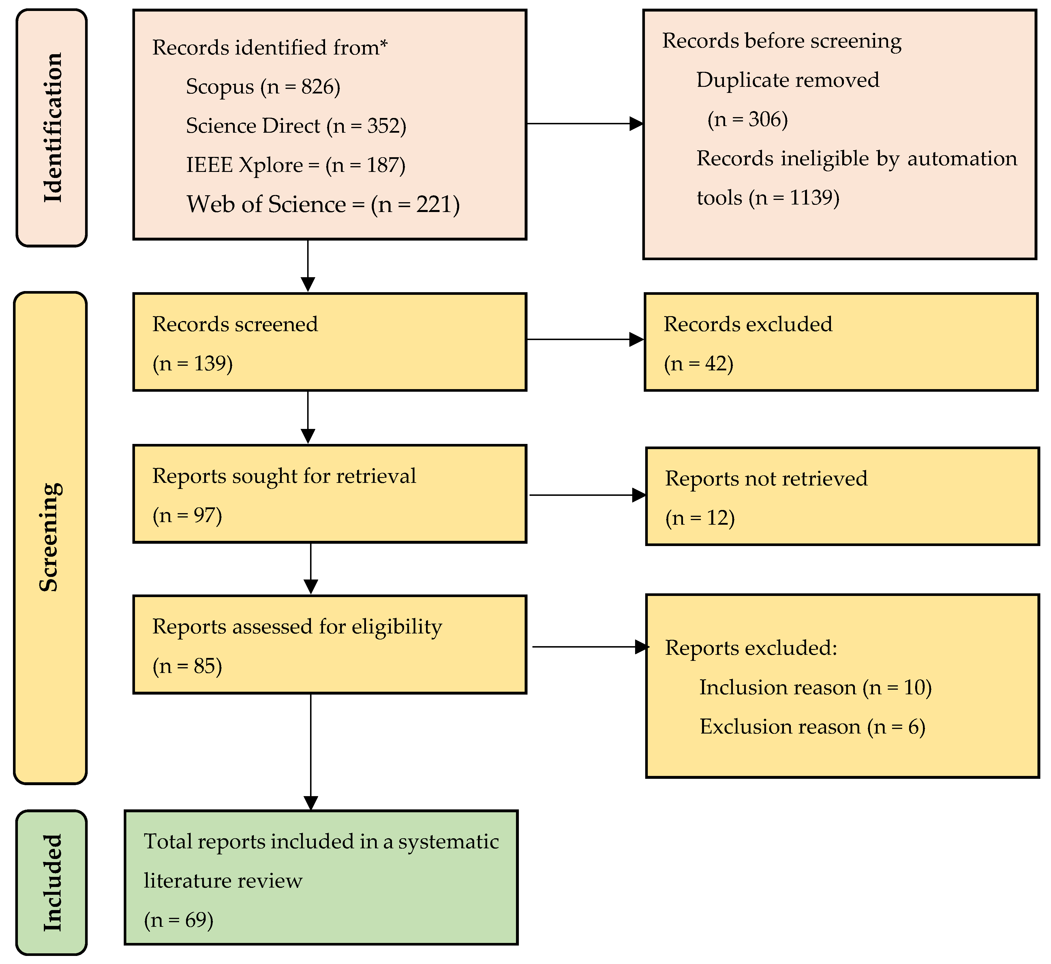
The present research is arranged as follows. Section 2 outlines the methods used to review the literature. Section 3 investigates BESS with respect to expansion planning. Section 4 and Section 5 reviewed its application and battery technology, respectively. Section 6 focuses on the study of battery degradation. Meanwhile, Section 7 reviews the objective function, design constraint, and algorithm of BESS optimization. Section 8 discusses the issues and challenges of BESS, while Section 9 concludes the research and provides areas for future works.

2. Methodology

The systematic literature review (SLR) was summarized using the preferred reporting items for systematic reviews and meta-analyses (PRISMA) approach. Data were selected from the Scopus, Science Direct, IEEE Xplore and Web of Science databases in three stages, namely identification, screening, and reporting. Figure 1, shows the identification stage, which is carried out by searching for related articles in each database, as illustrated in Table 1. The strategy adopted at the time of initial screening on the database is in accordance with the provision of the title, abstract, and keyword. This led to the realization of 1584 articles, of which 824, 352, 187, and 221 were from Scopus, Science Direct, IEEE Xplore, and Web of Science concerning the optimization of BESS and battery degradation, respectively.
After checking and removing duplicate reports and records marked as ineligible by automation tools, 139 papers were obtained for screening. The papers were selected in accordance with exclusion and inclusion criteria based on Table 2. Incidentally, 42 records were excluded, 12 were not retrieved, and 15 reports were omitted due to inclusion and exclusion criteria at the screening stage. Finally, the total number of comprehensive SLR articles to be reviewed are 69.
As a result, this SLR was carried out to respond to the following research objectives and questions.
1.
How does the development of BESS optimization affect expansion planning and the impact of the BSS applications on the grid or microgrid?
2.
How does the battery technologies use affect BESS? And what can affect battery degradation?
3.
How does battery degradation due to ambient temperature affect BESS optimization?
4.
What are the main parameters and variables in BESS optimization planning?
The number of publications on this topic has increased over the past five years, as shown in Figure 2. For example, from 2018 to 2021 there were 53 articles, with 16 new publications in October 2022.
Meanwhile, 69 comprehensive articles have been selected for review. The acquired data has a Q1 journaling tool from the Scimago Journal Rank (SJR). Table 3 shows the list of publications or journals selected for review.

Brief Review

Until now, the trends of BESS have been widely studied in several aspects. As explained in Table 4, a BESS is often applied to solve microgrid, grid-scale, and hybrid renewable energy system (HRES) problems. However, to obtain economical results, its sizing and siting was optimally analyzed with a significant dependence on the problem to be solved. BESS is usually used to solve problems related to system flexibility, such as demand load shifting, loss of load, avoidance of RES curtailment, and RES peak shaving. As its research progresses, it becomes increasingly important to consider the impact on battery health, as well as the choice of battery technology used, which can affect the system and its economic value. Battery health needs to be considered to ensure it does not experience degradation, when the BESS needs to be replaced. In general, the battery degradation factors considered during the optimization process are SOC, DOD, cycle number, and battery lifetime. Furthermore, studies have also been developed on the use of recycled batteries from electric vehicles with BESS integrated into the microgrid system. Research on the effect of temperature on the optimization of BESS was also considered recently. The temperature factor that affects BESS consists of operating temperature and ambient temperature. However, little research has been carried out on the effect of BESS environmental temperature optimization. Yuhan Wu et al. [31] conducted research on optimizing BESS considering the ambient temperature. However, in this research the temperature variable was not explained in sufficient detail.
This review provides a discussion about the expansion planning with BESS optimization by considering battery degradation due to ambient temperature to fill in the research gaps. Figure 3 shows the mind map of BESS relating to the application, batteries energy storage technologies, battery degradation, objective function, design constraints, optimization algorithms, and challenges used in this review.

3. Expansion Planning Overview

A combination of BESS technology and expansion planning is frequently adopted to overcome the issues of VRE integration. For example, generation expansion planning (GEP) tries to meet energy demands alongside several economic and technological restrictions. It determines the generating capacity of an ideal investment plan during a specific study period. Governments and decision-makers routinely utilize GEPs to select when and where to invest in generating technologies. Based on the decision factors, energy expansion approaches are broadly classified as GEP and transmission expansion planning (TEP). However, storage expansion planning (SEP) is widely used when dealing with BESS investment choices. In reality, creating, transmitting, and storing processes tend to be synchronized [5].
The main challenge of GEP is determining the appropriate capacity size, generating unit, and timing of a new facility’s building to fulfill the electric power requirement, at least during the planning period. GEP models are made more versatile by considering numerous goal functions and constraints as shown in Table 5. Its goal function typically consists of two major components, namely, investment and operation. To establish an optimal GEP strategy, different restrictions that impact the execution of the plan must be considered. There are two types of constraints, namely required and discretionary. One of the relevant limitations is ensuring the balance of electricity demand. Therefore, there is a possibility that minimizing total expenditures for a GEP project is not an effective target function, especially if there are other fascinating aspects that compete for attention. Consequently, issues related to GEP are frequently posed as a multi-objective optimization process. This approach can handle the simultaneous compromising of multiple goal-planning functions to determine which alternative capacity is the most effective. Several of these goals are intertwined, such as incorporating DSM and RES in the generating mix, reducing pollution, reliability, fuel consumption, costs associated with the intermittent nature of RES, and the risk of fluctuations in energy expenditure. All these are carried out to improve the flexibility of the GEP model [40,41,42].
SEP can be categorized by its storage capacity, geographical distribution, and mobility, in addition to the kind and quantity of BESS. Furthermore, energy storage systems are classified as either short or long-term, depending on their capacity. Short-term appliances, such as capacitors, flywheels, compressed air energy techniques, and BESS, stores energy from seconds to days. Certain long-term appliances, such as hydrogen storage and water reservoirs, can supply energy from one week to an entire season. BESS can also be classified as centralized or dispersed. When categorized by centralized, it refers to a single place. Even though most BESS are either centralized or dispersed, BESS can categorized by mobility such as on electric vehicles (EVs) [5].
The primary goal of decoupling is to ensure that cost-cutting initiatives are carried out by central planners (vertically integrated electrical firms) or politicians, as opposed to private investors. In the SEP model, reliability indices account for expected energy not served (EENS) or loss of load probability or expectation (LOLP/LOLE). There is also a possibility of adding any necessary technical constraints for unit commitment (UC) that are essential for scheduling the operation of the producing sector. These include minimal timeframes between turning on and off, beginning and shutting down, ramping up and down, as well as the least power outputs. There is a possibility that further operational reserve limits, such as the spinning types, alongside frequency and voltage support replacements, are imposed on the way the system operates [5].

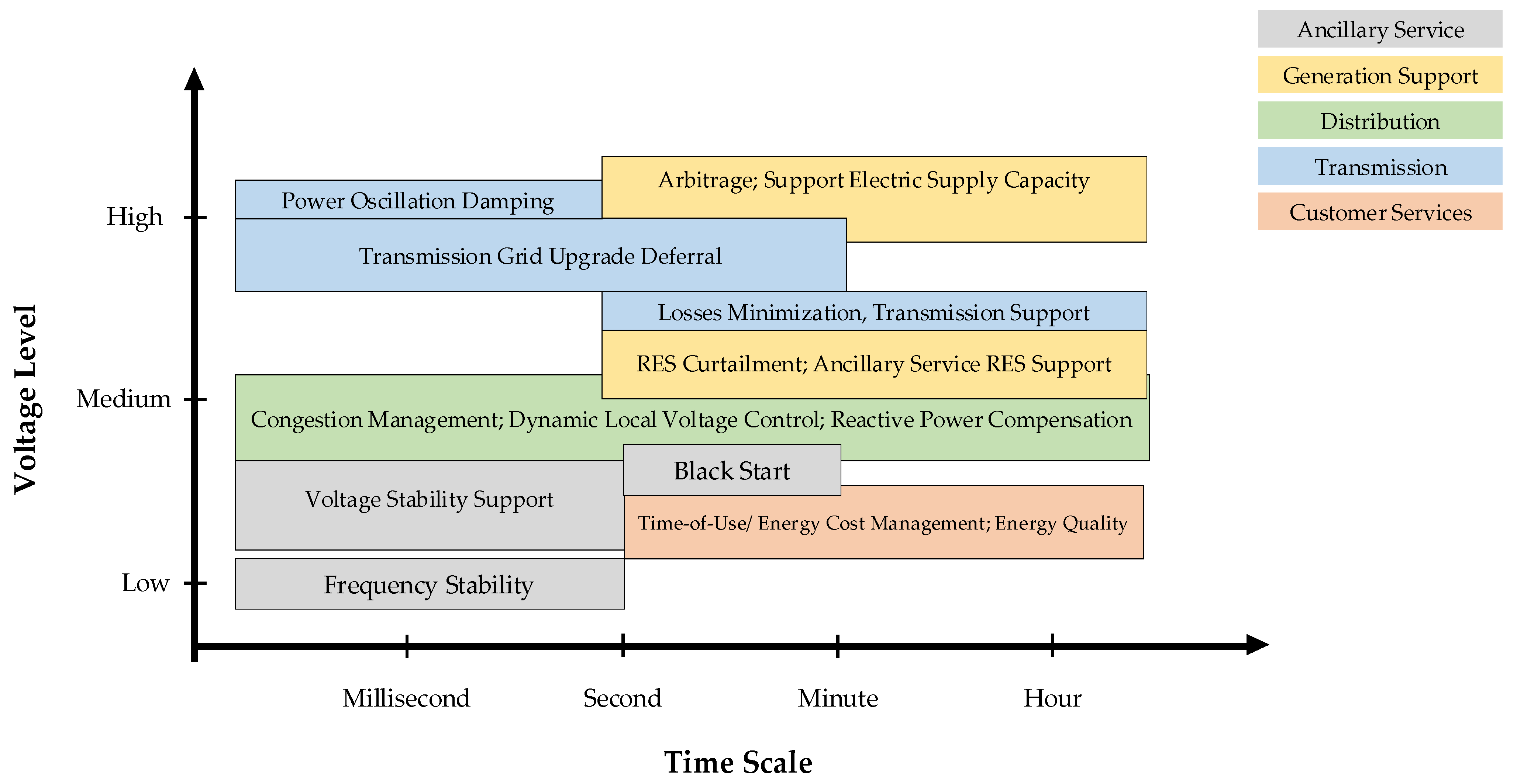
4. BESS Application Overview

BESS delivers various services to network operators, DG plants, energy retailers, and consumers. Figure 4 categorizes its applications in in the grid based time scale. Additionally, BESS consumption is classified in accordance with the time scale of its deployment, which ranges from milliseconds to hours. Its applications in grids or microgrids tend to improve power quality, voltage management, peak shaving, load smoothing, frequency control, and energy arbitrage [43].

4.1. Power Quality

The power quality index is used to measure voltage and current waveform distortions in pure sinusoidal ideals [43]. Variations in solar irradiance and wind speed trigger the negative effect of high-variance DG plants. Consequently, the BESS added to the DG plant has the potential to smoothen temporary power fluctuations. In this situation, it is viewed as an extra cost component with respect to the RES plant that serves as a revenue system. The provision of economic incentives to plant owners to reduce power fluctuations is a technique used to compensate for revenue losses [45,46].

4.2. Voltage Control

Capacitor banks, tap changers, voltage regulators, and static VAR compensators are equipment used to manage voltage during grid distribution. This is because DG injection makes the regulation of equipment at the substations useless, such as transformer tap changers, with many units scattered around the network selectively creating reactive power to allow for simpler voltage management. For example, a PV generator produces overvoltage at the network’s end [43]. Therefore, implementing BESS in such cases has been proven to be effective and potentially reduce overvoltage [47,48].

4.3. Peak Shaving and Load Smoothing

Both peak shaving and load smoothing aim to reduce the maximum amount of power visible to the system by striking a balance between the generation profile and demand. This approach produces real-time network congestion solutions by minimizing conductor overloads caused by the generation of peak power loads. Furthermore, peak shaving and load smoothing help to reduce network losses. BESS operations also reduce system losses by increasing load-to-local-generation profile matching [43,49].

4.4. Frequency Regulation

In an auxiliary service market, frequency regulation is typically provided by generators connected to a transmission network. Interestingly, it is described as a commercial offering. However, in recent years, generators and energy storage devices connected to the distribution network also provided this service. This is possible because the distribution network has become more decentralized. Additionally, the increasing demand for renewable energy brought about the modification of this policy. Both the generator and BESS use drop control to monitor the frequency and adjust the power output appropriately. In this scenario, BESS allows restrictions to be specified by the state charges (SOC) [50,51].

4.5. Energy Arbitrage

Energy arbitrage is the process of simultaneously purchasing and offering energy supplies in the marketplace. It was only initiated by commercial users because the power sectors of most countries do not have any form of regulation. The application of BESS pairs with DG or load, in which storage units are utilized to redirect energy production or generation, is aimed at maximizing profit irrespective of the fluctuations in market prices [43,52]

5. Battery Energy Storage Technologies

LA, Li-Ion, NaS, and RF are grid applications’ most common battery technologies. These are classified according to their energy density, efficiency, lifespan, and cost when coupled to a storage network, as shown in Table 6, Table 7 and Table 8. The LA battery has high efficiency between 80 and 90% and low costs within the range of 50 to 600 $/kWh [52,53] However, when compared to other technologies, it has a significant disadvantage in terms of lifespan (approximately 2500 cycles) [54] and low energy density (within the range of 20 and 30 Wh/kg). A high discharge depth shortens an LA battery‘s life [52,55].
The characteristics of Li-Ion batteries are based on the chemical composition of both the cathode and anode, which typically consists of graphite and lithium metal oxide. Interestingly, the cathode and anode give the battery its name and power, respectively. This technique is highly efficient, with a maximum efficiency of approximately 90%. On the other hand, some commercial devices boast reported round trip efficiencies of more than 95% with energy density within the range of 90 to 190 Wh/kg [56] and extended service life of relatively 10,000 cycles [54]. Cell temperature, an essential element in the deterioration process, significantly affects the battery life [30]. Li-Ion batteries are commonly found in electronic devices and recently emerged as the industry standard for EV. This technology is suitable for grid-connected network applications, even though it is still somewhat expensive. Presently, there are several Li-Ion technologies, for example, lithium manganese oxide (LiMn2O4), lithium cobalt oxide (LiCoO2), lithium nickel cobalt aluminum oxide (LiNiCoAlO2), lithium iron phosphate (LiFePO4), and cobalt-based Lithium nickel manganese oxide (LiNiMnCoO2) [57]. Table 7 and Table 8 show details of the Li-Ion and nickel-based battery specifications, respectively.
NaS batteries have a high working temperature (approximately 300 °C), efficiency (>80%), energy density within the range of 150 to 240 Wh/kg, and a long lifespan of relatively 4500 cycles [58,59] As a result, this technique has been utilized to lessen the effect of renewable energy-based generators as an in-grid [58,60]. Vanadium redox flow batteries (VRB) batteries comprise two containers, one containing two chemical reagents and the other two electrodes partitioned by a membrane. Incidentally, when the two components combine, it results in an oxidation reaction. One of the containers holds the chemical reagents, while the other contains the electrodes. The amount of stored chemicals contributes to the flow cell’s total energy capacity. Meanwhile, the electrodes and membrane filtering system are responsible for individual energy capacity flow cell. The power and energy ratings are separated, resulting in the increased design and operational flexibility. The energy density of VRB is relatively low, ranging from 15 to 30 Wh/kg, and its efficiency is approximately 75% in some cases [61]. On the other hand, they are not constrained by reactant life cycles or discharge depth [62]. Due to the low costs involved in their maintenance and operation, VRB have been suggested as viable options for large-scale grid-based energy storage [63]. The reactants have been investigated, and several chemical compositions have been proposed. The most utilized ones are vanadium and Zn-Br [64].

6. Battery Degradation

Battery degradation leads to a reduction in its capacity and efficiency and even safety problems. The term cycle life refers to the total number of times a battery can be discharged or charged before it is replaced [72]. Nonlinearity in battery degradation can be traced to a variety of causes, such as SOC, high temperature, depth of discharge (DOD), and charge or discharge current rate [73], as shown in Figure 5. One of the issues contributing to the short lifespan of Li-Ion batteries, for example, is the highly utilized DOD, which tends to significantly reduce the total number of cycles [74,75].
The remaining useful life (RUL) and state of health (SOH) are the most critical factors in predicting Li-Ion battery degeneration. Generally, usage capacity, energy, and accessible power, which diminish with battery age, influence SOH and RUL [76]. Although SOH tests detect a decrease in performance, they also prevent potential accidents [77]. The accuracy with which one may anticipate the RUL of a given battery capacity relies on several factors, and the most important is the ability to calculate the SOH. Managing discharge problems, improved performance, and optimized operation requires precise and reliable prediction algorithms to determine a battery SOH and RUL.
SOH refers to the percentage of a battery cell’s capacity that is still usable and used to quantify the entire aging degree. This value is expressed as a percentage [78] and ideally, the SOH of the new battery should be 100%. The decreasing trend of SOH is due to the accelerated aging of the battery, which is one of the reasons of the increased cycle times. When the state of health reaches the failure threshold, the battery becomes ineffective [79]. The formula for SOH is written in Equation (1).
SOH t = C t C 0
where C t and C 0 denote the t-th cycle and initial battery capacity. The maximum capacity of the battery tends to drop in accordance with the number of times it is cycled, with continuous increase in the battery’s internal resistance. Generally, a battery fails when its internal impedance increases to a level that is twice as high as its initial impedance. Several performance parameters, such as power and the number of charge and discharge cycles, can also be used to define SOH. Further studies must utilize a wide variety of methods or models to estimate SOH, such as the use of direct measurement and indirect analysis. By measuring the standard aging characteristic parameters of the battery, the direct measurement technique determines the value of its current capacity, internal resistance, cycle times, etc. This is the technique through which the values of the current state’s identifying parameters are determined. Examples of direct measurements are counting ampere hours, cycle numbers, measuring internal resistance and impedance. The indirect analysis consists of obtaining the SOH value by estimation based on online observable data from health indicators that have a high link with the performance and characteristic parameter degradation that occurs with the SOH condition. Model-based analysis, data-driven analysis, and hybrid analysis are examples of indirect analysis [80].
Wei J et al. [81] monitored the estimated diagnosis of battery SOH with three stages. In the initial stage, a particle filter (PF) technique was initiated, followed by the execution of a procedure to update the particle’s time. The support vector regression (SVR) model was also used to estimate the capacity in each battery cycle number in the second stage. This SVR model is trained with characteristics collected from sensor data during constant-voltage (CV) charging mode at cycle number, to determine the charged capacity. The third stage updated the particle constitutes, which can be resampled based on their normalized importance weights. In accordance with the PF-based estimator, the anticipated capacity at the cycle number is considered as a Gaussian distribution, whose variance and mean are obtained. SOH is further defined as the ratio between the capacity of a new battery and the expected capacity. In general, the SOH estimation flowchart can be seen in the flowchart in Figure 6.
RUL refers to the information on the remaining life of a battery. It is imperative to change old and damaged batteries whose SOH has reached 0%, to guarantee the safety of the system and hence prevent problems [80,82]. The formula for RUL is written in Equation (2):
RUL t = t t e o l
where t and t e o l denote the t-th and number of cycles remaining at the completion of a battery’s life. It is difficult to compute the RUL of a battery due to several variables, such as its present health condition, historical data, and failure. Therefore, further study needs to be conducted on the prediction of batteries’ RUL. Presently, there is no standard framework that is considered the optimal model for estimating RUL due to a lack of available data, model complexity, and system limitations. In general, RUL prediction methods can be categorized as physics-based, mathematical, data-driven, or hybrids [80].
Wei J et al. [81] also predicted the RUL of a battery using the SVR-based model using a flowchart as shown in Figure 7. Monitoring the prediction of RUL starts with developing a model that has been trained using extracted sensor data features and predicted capacity for SVR-based input models. Wei J. et al. applied the average degradation parameter to characterize the expected capacity distribution in this section. The result showed that RUL is considered the n + 1 after the predicted capacity has reached the EOL threshold.
The diagram in Figure 8 illustrates the connection between SOH, RUL, and the modeling of battery degradation. Some preliminary research developed a battery deterioration mechanism model using a framework that incorporated SOH and RUL [76]. The elements that influence general battery deterioration and failure were further explained in the SOH estimation model. Furthermore, its diagnostics and estimation help boost RUL battery modeling by determining how much time or cycles are left to attain 80% SOH. As a result, the reliable prediction of SOH and RUL is required for modeling battery deterioration behavior.
The SOH of a battery is measured in terms of its present ability to supply a certain quantity of energy in comparison to the initial capacity. At the same time, the RUL is helpful for monitoring the state of the battery and is also essential for executing operations that evaluate its degeneration. Due to the nonlinear nature of battery deterioration, it is necessary to have appropriate RUL estimations that are based on aging processes and suitable life models at various fading stages [76]. This entails calculating the time until a battery reaches its EOL. It tends to occur when the battery has reached the failure threshold. Moreover, the time left and the total number of charge-discharge cycles are considered [83]. The RUL estimation and degradation process are intimately linked to the working circumstances and dependability of Li-Ion batteries. Previous studies have reported that the successful prediction of the RUL prevents failure and timely functional maintenance without irreversibly harming the battery [84].
Scholars estimated the RUL using several different methodologies, as shown in Figure 9. These tend to be broken down into one of the four categories, namely based on physics, mathematics, data, or hybrid models. The amount of time a battery is going to be valuable is evaluated using a model-based technique. Therefore, a model that is representative of a battery application found in the real world, as well as an estimated algorithm used to predict voltage or other characteristics, needs to be developed. Empirical, analogous circuit and electrochemical models, including Kalman filters, are a few examples of the various methods that fall under this category. Data-driven RUL estimation is a prediction method that collects excess information and continues recording until battery health reaches its limit. Meanwhile, applying a hybrid model implies combining a model-based method with a data-driven model [76].
Table 9 reviews variables used to optimize BESS capacity size and placement with battery degradation models, which vary in different studies. Aside from the SOH and RUL models, preliminary research also used fading capacity and residual battery life for BESS optimization. Table 10 reviews the algorithm used for battery degradation models for BESS optimization.
Battery lifespan is influenced by calendar and cycling aging. However, this is also determined by cycle or float lives [93]. Even though the computation of the BESS life value tends to be inaccurate, its datasheet is dependent on two limits, cycle and float lives. Both restrictions are measured in years, and when the BESS maximum life is equal to or exceeded by its float life, it is said to have a floating life equal to or exceeds its maximum life. The cycle life is represented as the maximum number of charge and discharge cycles that can occur prior to the BESS failing, and it varies depending on the technology of both the BES and the DOD [38].

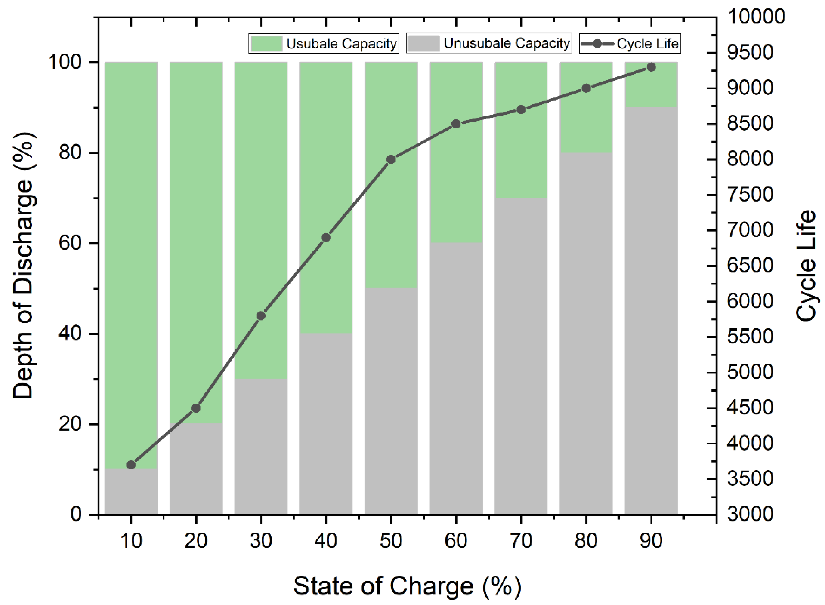
6.1. Battery Degradation Due to Changes in Ambient Temperature

The performance of lithium-ion batteries and their lifespan is significantly influenced by temperature. When exposed to high temperatures, its rate of degradation is significantly accelerated. Li-Ion batteries are temperature-sensitive [9], and their performance is affected not only by the temperature of the cell itself but also by the environment in which it is located. Battery degradation is caused by a combination of the SEI and the loss of active material. The one brought about by SEI is the most common and fundamental cause of capacity fade rate in batteries. As a result of the high temperature, the surface particles of the electron undergo a rapid development of SEI, thereby causing the battery’s capacity to reduce [94]. According to some literature [95] on the systematic establishment of the theory on SEI growth and reduction in battery capacity, it was asserted that temperature changes trigger capacity fade due to alterations in the SEI layer. Incidentally, SEI growth can occur in idle situations, during the cycle, and during temperature changes. Some literature [96] clearly stated that temperature changes severely affect battery degradation. This process is of two types, namely actual and temporary capacity fading and loss. The actual capacity fading suggests that there has been irreversible cell loss due to the ingestion of lithium-ion. The high temperature of the battery accelerates the rapid rate of cell deterioration. On the other hand, a temporary capacity loss is caused by a drop in temperature during a specific cycle. It can be restored if the battery temperature returns to a certain level.
The literature [97] focuses on the ambient temperature impact on a battery’s lifespan. The formation of the film on the electrodes of Li-Ion batteries explains the effect that the surrounding temperature has on its lifespan. This is because of the oxidation of the cell, proven by the film produced on the electrodes. It causes an irreversible increase in the Li-Ion battery’s internal resistance, ultimately leading to damage. The findings on the simulation process show that higher temperatures during idle battery scenarios resulted in extreme capacity loss and self-discharge.
Some studies on calendar aging reported that it is related to temperature. Battery aging testing is performed at different temperatures, SOC, and end-of-life. The tests were conducted in a laboratory with temperature control facilities and charging or discharge operations. In reality, the battery is in extremely harsh operational conditions. The results of Li-Ion testing for EVs are reported to last 2000 and 800 cycles at temperatures of 25 °C and 55 °C, respectively [98]. Additionally, testing the influence of battery temperature due to discharge rate differences such as 1C, 2C, 3C, and 4C was also conducted [99]. It is possible to determine the varying contours due to the changing temperatures of the battery cells and their discharge at a consistent rate.
The pace at which capacity is lost is significantly affected by the temperature of the surrounding environment. Meanwhile, when it is greater than 35 degrees Celsius, it triggers more changes in the composition of the electrolyte due to the substantial temperature rise. This causes the process at which active lithium is utilized to quickly move forward [100]. As a result, the battery’s capacity starts to decrease at various room temperatures, as shown in Figure 10. It is evident that when the perimeter temperature is greater than 35 °C, the capacity fades level drops significantly during the first 50 cycles. This phenomenon occurs while the battery is being used. When the temperature is 55 °C, the maximum capacity fades, while the temperatures of 25 °C and 35 °C are projected to be the same [100].
Characteristics of the capacity fade rate of the battery which is affected by the ambient temperature as shown in Figure 11. Yuhan Wu et al. [31] stated that LiFePO4 battery degradation caused by the average temperature in BESS is modeled by combining calendar and cycle aging. This model is depicted by a single operating cycle, as shown in Equations (3)–(8). By knowing the characteristics of the battery aging cycle to set the optimal operating temperature of BESS, it can reduce the battery degradation rate so that the battery life is longer.
ξ = ξ c a l + ξ c y c
ξ c y c = f d , s o c S O C a v g
ξ c a l = i = 1 n f d , d o d D O D i f d , T T i , a v g
f d , s o c S O C a v g = k 1 S O C a v g 2 + k 2 S O C a v g
f d , d o d D O D i = k 3 D O D 2 + k 4 D O D
f d , T T i , a v g = e k 5 / T / k 6 ,   298 K T 273 K e k 7 / T / k 8 ,   333 K T 298 K
where ξ represent of battery degradation from calendar aging ( ξ c a l ) and cyclic aging ( ξ c y c ). n is the number of cycles charged or discharged in one day. S O C a v g represents the average SOC, D O D i depicts the difference between the i-th charge and discharge cycles DOD, and T i , a v g is the average temperature in BESS. In most cases, the value of the k parameter is determined by the experimental observation [31,35].

6.2. Battery Thermal Management

Complex electrochemical reactions and electric-to-thermal conversion determine the thermal characteristics of a battery [101]. The production of heat by Li-Ion batteries is a complex process that involves a knowledge of how the rate of electrochemical reaction varies with time and temperature, in addition to how current flows within the battery [102]. Simply, heat generation of the battery is written as Equation (9):
Q = I U V I T d U d T  
where Q denotes the rate of heat generation, I denotes the electric current flowing through the cell, U denotes the open-circuit voltage, and V represents the voltage of each individual cell in the Li-Ion batteries. In general, the thermal model of a battery has been examined according to the dimensions of the battery as well as the physical mechanism (electro-thermal model, electrochemical thermal model, and thermal runaway propagation model) (lumped model, 1D, 2D, and 3D). In most cases, the charging and discharging procedures for Li-Ion batteries result in the production of three distinct types of heat. These forms of heat include activation of irreversible heat as a result of the polarization of an electrochemical reaction, joule heating as a result of ohmic losses, and reversible reaction heat as a result of the change in entropy that takes place during the charging and discharging processes. Consequently, if the heat created by the battery while charging or discharging is not correctly dissipated, the temperature of the battery may grow because of heat accumulation, which may have a severe influence on the battery’s performance, life, and safety [102].
The thermal management process, which is a critical component of the battery management system, is most concerned with estimating the precise state of temperature (SOT). Using more traditional measurement methods, such as thermocouples, it is simple to obtain an accurate reading of the temperature at the surface of the battery. Nevertheless, the temperature on the inside of the cell during transients is significantly different [103]. In general, the SOT estimation methods can be broken down into four categories: the direct measurement method, the electrochemical impedance-based method, the model-based estimation method, and the data-driven method.
Using a direct measurement methodology, researchers proposed ways for monitoring the temperature of a battery’s internal layers. Temperature micro-sensors are integrated into the interior layers of the battery cells in these technologies. Thermocouples and resistance thermometers are the two most common types of sensors used to indicate the temperature of a battery’s interior. The model-based estimation approach typically makes extensive use of numerical thermoelectric and thermal models when attempting to determine an object’s internal temperature. To construct thermoelectric and thermal models such as the lumped-parameter battery model and the distributed battery thermal model, it is very required to understand heat generation, conduction, dissipation, balancing, and thermal boundary conditions. A few different approaches for calculating the temperature of a battery based on electrochemical impedance spectroscopy EIS measurements have been proposed in the electrochemical impedance-based approach without first constructing a thermal model. Temperature can be linked to impedance indicators acquired via EIS. These indicators include phase shift, real part amplitude, and imaginary part amplitude, per the most recent data-driven strategies. Data-driven approaches were used to estimate the temperature of the batteries inside [103].

7. Objective, Design Constraint, and Algorithm BESS Optimization

This section explains the objective functions frequently reported by previous studies, design constraints, algorithms used for BESS optimization, and a review of its state-the-art development. The steps involved in BESS optimization are depicted in the flowchart shown in Figure 12. This starts with collecting input system data, then determining the direction of the model development, selecting an objective function and design constraints, optimizing strategy and algorithm, and finally evaluating the optimization results.

7.1. Objective Function BESS

Since BESS plays an important role, its sizing is essential to ensure the normal functioning of distribution networks. An accurate and realistic model improves the operating systems from an economic and safety standpoint [104]. BESS optimum sizing is centered on finding its optimal capacity and the ability to minimize distribution network operating costs while meeting performance goals. Its investment cost is an essential component in calculating the distribution network operating expense. Moreover, this is affected by the investment payback period. As a result, BESS life is significant, and the number of cycles it can complete as well as the SOC at which it runs, are the two most important parameters used to determine the longevity of the battery. To assess the expenses linked to BESS, the anticipated lifespan was used [105]. In [106], the lifetime was determined by predictive models. The main objective of the study is to reduce costs, integrate RES, analyze its effects, and obtain benefits for the network.

7.1.1. Objective Function BESS to Reduce Total Cost Storage Expansion Planning

In the literature [32] the objective function was considered to reduce the total cost of storage expansion planning on the microgrid. It is defined as follows
M i n   i G d h F i P i d h ( ) , I i d h ( ) + d h ρ d h P d h ( ) M + s p r s b K d h L S b d h s v + i B b K P i b R C P i a + C M i + C i b R C E i a + C I i a
The first two-term Equation (10) indicates the operating cost of the microgrid when connected to the grid. Where b, d, h, i, l, s and B are the bus, day, hour, distributed energy resources, lines, scenarios, and battery technologies indices, respectively. F i represents the microgrid local DG units cost function, P i d h ( ) is DG output power, I i d h ( ) depicts the commitment state of dispatchable units, ρ d h is electricity market price ($/kWh), and P d h ( ) M illustrates the power transferred to and from the utility grid. The third term accounts for the costs of dissatisfying the requirements of the MG demand. Due to insignificant changes in the demand for microgrids, the output of generators distributed at the price of electricity during the planning period need to consider the historical data of one year. Where p r s is the probability of islanding scenarios, L S b d h s depicts load curtailment, and v represents the value of lost load ($/kWh). Incidentally, the value of lost load (VOLL) measures the economic losses associated with underserved energy. It depicts the willingness of customers to pay for reliable electrical services. This number is not dependent on the time or length of the outage rather, it is determined by the kind of consumer and location. The last term reflects the costs of BESS. Where C i b R ,   P i b R is BESS rated energy and power, C E i a , C P i a depicts annualized energy or power investment cost of BESS, C I i a is the cost of BESS installation on an annualized basis and C M i represents the annual operating and maintenance cost of BESS.
In addition, there is also a BESS objective function to be applied in storage expansion planning on the grid. Based on the literature [35], it is stated as follows
min s S π s t T i I A i G P s , i , t G 2 B i G P s , i , t G + k m B r F s , k m , t 2 R k m V k m 2 C A P L t + k K j J E ¯ j , k E S C j E + P ¯ j , k E S C j P 365   T j L t
Equation (11) shows the objective function that considers the exchange between investment costs and BESS operations. Due to this, BESS can demonstrate energy time-shift applications, which, in turn, contributes to the reduction in the day-to-day running expenses of the network. This is accomplished through a series of hypothetical situations that reflects the whole life span of BESS. The first group indicates the total operating cost of DG, where S represent the set of future network operation scenarios, T is the time intervals, π s depicts the probability value of the scenario s, I represent the generation units, A i G , B i G illustrates a generation cost function, and P s , i , it is the scheduled power output of a thermal unit. The second term shows active power losses on the network, F k m , R k m , V k m depicting thermal limit, resistance, and the voltage level of the line. B r is an index of branches connecting pairs of nodes k m , while C A P L represent energy price for active power losses. The last term illustrates the investment cost of BESS, where K represent of index of transmission grid nodes, J is the set of energy storage technologies, P ¯ j , k E S , E ¯ j , k E S represents the rated power and energy capacity of BESS, C j E , C j P depicts the investment costs of battery technology, and T j L t is the service lifetime battery.

7.1.2. Objective Function BESS of Life Cycle Cost Energy System

This energy system objective Life Cycle Cost (LCC) is used to minimize the total planning costs calculated only from BESS [91]. It is defined by some literature as follows:
Min   LCC = C b a t t + C O M
C O M = y = 1 Y 1 + r Y y [ t = 1 8760 ( C o u t . y t + C f i t . y t + ξ C b a t t ] 1 + r Y
C b a t t = C a p b a t   μ b a t t
C o u t . y t = P y g b t + P y g l t t   b u y
C f i t . y t = P y b g t + P y p v g t t   s e l l
Equation (12) is an LCC consisting of the initial investment cost of BESS ( C b a t t ), including the cost of operation and maintenance BESS ( C O M ). Furthermore, Equation (13) is used to obtain the operation and maintenance costs where y and t is the index year, and time interval respectively, C o u t . y t depicts electricity bills, and C f i t . y t is the benefit from selling electricity to the grid. Equation (14) represents the initial investment cost of BESS, where C a p b a t depicts the capacity of the battery, and μ b a t t is the unit capacity price. Additionally, Equation (15) is used to calculate the electricity bills where P y g b t represents the power flow from grid to BESS (kW), P y g l t is the power flow grid to the line, and b u y depicts electricity price. Equation (16) is the profit realized from selling electricity to the grid, where P y b g t represents power flow battery to the grid, P y p v g t illustrates the power flow PV to the grid, and s e l l is feed-in tariff.

7.1.3. Objective Function BESS for Battery Degradation Cost

According to the literature [107], the optimal scheduling of BESS is supposed to minimize the degradation costs, which are the proposed objective function. The intended degradation charge model accounts for the nonlinearities of battery life. As a result, the ideal SOC profile is the same regardless of the degradation cost model if the pricing pattern is either too flat or there are excessive disparities between the maximum and minimum prices. The objective function is stated in the following equation:
M i n   t ( λ t P g r i d , t + C E S o C t a u x C E S o C t 1
Equation (17), is the optimal cost scheduling of BESS. It consists of power grid expense and degradation cost function for optimal scheduling, where t represents index of time interval, λ t is electricity price, P g r i d , t represents the power from the grid, C E denotes degradation cost for scheduling, S o C t a u x ,   S o C is auxiliary and actual SOC BESS.

7.2. Design Constraint

In an arbitrary situation, the requirements or needs that must be considered are referred to as constraints. The power balance between the consumption and generation aspect is the most important constraint [108]. In distribution networks, electricity is imported or exported to the major grid, although this is often limited [109], to BESS-based operations [31]. The following are the most important limitations in maximizing the BESS size.

7.2.1. BESS Operation Constraint

The most common operational constraints when sizing BESS optimization techniques are charge or discharge or SOC constraints. In addition, battery degradation rate and life span needs to be regarded. The literature published by [110,111,112,113] reported otherwise, that the optimization of the BESS must consider the SOC. This constraint was taken into [114,115,116,117,118] consideration by maximizing BESS power loss, capacity, method, power balance, and battery lifecycle. In [32], the impact of BESS operation constraints is analyzed based on microgrid application and stated as follows
P i m i n x i b P i b R P i m a x x i b
α i m i n P i b R C i b R α i m a x P i b R
P i b R , C i b R denote power and energy rating BESS. The maximum and lowest BESS power ratings of P i m i n ,   P i m a x are represented by Equation (18). To determine the current investment status of BES technology, the binary variable x is used. Equation (19) utilized the power capacity to compute the maximum discharge time and measure the BESS capacity, where α i m a x ,   α i m i n indicates the highest and lowest possible energy to power rating ratios for the BES.
0 P i b d h s d c h P i b R u i b d h s
P i b R 1 u i b d h s P i b d h s c h 0
The charging or discharge power of BESS P i b d h s c h ,   P i b d h s d c h is limited depicted in Equations (20) and (21), where i, b, d, h, and s denote the distributed energy resources, bus, day, hour, and scenarios indices, respectively. u i b d h s is BES operating state. BESS power turns negative and positive while charging and discharging, respectively. The current state of the BESS operation is determined by the value of the binary variable u. BESS can only flow when it is equal to one, and charges when it is equivalent to zero. The magnitude of the discharge has a direct bearing on the BESS life cycle, which varies from the diverse technologies. The BESS cycle refers to a complete one that includes both charging and discharging of the battery.
ξ i b d h s = u i b d h s u i b d h 1 s u i b d h s
d h p r s ξ i b d h s 1 T m N K i m W i b m
Equation (22) is used to determine the BESS cycle, where ξ i b d h s is BESS cycle indicator. Every time the charging process begins, the value is bound to be one, otherwise, it is zero. During the planned time horizon, the total BES cycle need not exceed the specified lifespan regarding the determined maximum DOD and the life project stated in Equation (23), where K i m is BESS lifecycle, and W i b m represents a binary variable that reflects the value of the BESS maximum DOD.
m N W i b m   x i b
C i b d h s = C i b d h 1 s P i b d h s d c h T η i P i b d h s c h T
( 1 m N Υ i b m W i b m ) C i b R   C i b d h s C i b R
Equation (24), assures that for each BESS deployed, only one maximum depth of discharge value is evaluated. According to Equation (25), the energy stored at each time interval is equal to the preceding period minus the discarded or charged energy, where C i b d h s is stored energy BESS during each interval. Meanwhile in Equation (26), BESS cannot be discharged with less energy than the minimum value specified by the maximum depth. This is not indicated by the discharge, nor can it be charged with more energy than its rated capacity allows during the process. Where Υ i b m is maximum DOD BESS.

7.2.2. Battery Degradation of BESS Constraint

Battery degradation in BESS is important to consider. Cardoso et al. [27], stated that the total annual electricity cost savings from PV and BESS can be reduced by 5–12% by solely considering the battery degradation constraint limitations. Furthermore, some literature [35] stated that a battery degradation model is based on cycling and aging conditions. Afterwards, it is used in the BESS operation constraint to support its optimization by lowering the planning cost of energy storage.
γ I d l S o C j , k = A j I d l S o C j , k 2 + B j I d l S o C j , k + C j i d l
γ C y c D o D j , k , n = A j C y c D o D j , k , n 2 + B j C y c D o D j , k , n
Equations (27) and (28) are capacity fade rates during idling and cycling conditions resulting from historical data on battery characteristics and adjusted to the least squares fitting method [35]. Where j , k , n are the battery technology, transmission grid nodes, and charge/discharge cycles indices, respectively. γ I d l , γ C y c is the capacity fade rate during the idling condition, and A b I d l ,   B b I d l ,   C b I d l , A b C y c , B b C y c is a quadratic, linear, and constant of the degradation functions during idling and cycling.
0 E s , j , k , t B E S S E ¯ j , k B E S S 1 γ I d l S o C j , k + n y n γ C y c D o D j , k , n Y s
BESS charging is limited to the energy rating of those batteries which continues to fade due to the life horizon, depicted in the Equation (20), where E b , i , y , d , t B E S S is the BESS continuity energy, and E ¯ b , i B E S S represents the installed BESS Energy. The value can be 0.5 for half cycles and 1.0 for full ones y n . Y represents years for the number of the scenario s .
r e m j , k = 1 γ I d l S o C j . k + n y n γ C y c D o D j . k , n T j L t
E o L j r e m j . k 1
Equation (30), r e m j , k is a formulation of the remaining BESS capacity at the end of battery service life due to idling degradation and cycling. T j L t represents service lifetime period BESS of a manufacturer. The selected operating strategy is dependent on the remaining BESS capacity. r e m j . k ensures that the remaining capacity is not less than the EOL threshold, moreover a constraint is applied in Equation (31).

7.2.3. Power and Energy Balance Constraint

When it comes to BESS size, the power, and energy balance between demand and generation is crucial. In the following literatures [112,116,118,119,120,121,122], the energy and power balance are constraints in the process of optimizing the size of the BESS. Based on [32], the power and energy balance constraints are expressed as follows
g G , W μ i b P i d h s + b B P i b d h s c h + P i b d h s d c h + i I ψ i b f i d h s + P d h s M + L S b d h s = D b d h
The balance of power and energy constraints are stated in Equation (32). This guarantees the amount of power provided by the distributed energy resources (DER) installed on that bus, plus or minus the amount of electricity going into or emanating from it, is equal to the quantity of power locally needed on that bus. If there is not enough generation to maintain BESS balance, the load is reduced, and the strength tends to be positive while the system is discharging and negative while it is charging. However, if the power is flowing from the utility grid into the microgrid, then it has a positive value, otherwise, it is negative. Where i, b, d, h, and s are the distributed energy resources, bus, day, hour, and scenarios indices, respectively. μ i b is a generation-bus incidence matrix element, P i d h s is DER output power, P i b d h s c h ,   P i b d h s d c h depicts BESS charging and discharging power, ψ i b represents a line-bus matrix element (one if line l is connected to bus b, 0 if otherwise), f i d h s denotes distribution line power flow, P d h s M is electricity moved to and from the utility grid, L S b d h is the load shedding cost, and D b d h is total load demand.
P M , m a x z d h s P d s M P M , m a x z d h s
0 L S b d h D b d h C D b d h
f l m a x f i d h s f l m a x
Equation (33) is the limitation of a microgrid network of power transfer to the grid. Furthermore, Equation (34) is the limit for load reduction, where P M , m a x denotes the maximum power capacity of the microgrid to the utility grid, z d h s is microgrid/utility grid status, D b d h ,   C D b d h represents the sum of all load demands as well as the critical load demand. Equation (35) is the amount of power that flows through a distribution network microgrid due to channel capacity constraints, where f l m a x is the maximum power capacity of distribution line.

7.3. Optimization Strategy and Algorithm

Size, capacity, cost, and lifetime are all aspects of the BESS that need to be improved. Existing research on BESS sizing-related problems is categorized according to grid scenario, goals that need to be achieved, the strategy applied, test bus, and various advantages and limitations to optimize the different algorithms. These include genetic algorithms (GA), particle swarm optimization (PSO), dynamic programming (DP), taboo search, fuzzy PSO, and bat algorithm. Simulation and modeling technologies such as PSLF, MATLAB, CPLEX, OpenDSS, GAMS, Gurobi, PowerFactory, and DIgSILENT are extensively used to improve BESS sizes. MATLAB is also a viable choice. Moreover, several research use a test bus from the IEEE study case to evaluate the system’s performance instead of the current test systems [44]. The following are some of the most often used algorithms for predicting BESS size.

7.3.1. Probabilistic

Since several parameters tend to be improved, the probabilistic technique is regarded as one of the simplest ways of measuring BESS. The fundamental constraint of such a method is the number of parameters that need to be examined. Based on preliminary research, the probabilistic method was discovered to be the most useful approach for calculating the uncertainty parameter of the optimization process to obtain the best BESS measure [123,124,125,126,127,128,129]. Its key benefit is the need for a small amount of data to conclude. As a result, probabilistic approaches are excellent in circumstances where information is scarce.

7.3.2. Deterministic

The deterministic techniques examine various electrical configurations, system components being altered, and how they need to be optimized based on preset principles. A deterministic technique is a direct approach to cost [130] and capacity [131,132] alongside the optimization process investigated by some other analysis.

7.3.3. Rule-Based Optimization

The rule-based optimization (RBO) method defines an expected solution, such as fuzzy logic. In accordance with the following literature [131,133,134,135,136], optimization of BESS sizing is realized using fuzzy logic. Based on the research, a fuzzy-based method was adopted to reduce both the RES and the cost of BESS [137]. According to the data, an ideal BESS reduces microgrid costs by 3.2 percent, and battery longevity significantly affects MG costs. The primary advantage of utilizing a fuzzy optimizer is that either the total number of parameters is unknown or the scale of the optimization issue is unaffected by any change [138].

7.3.4. Mathematical-Based Optimization

The most comprehensive method is mathematical modeling when it comes to finding the solution to the BESS sizing-related problem. This approach for determining the optimal size of the BESS is categorized as linear programming (LP), nonlinear, or mixed-integer programming (MILP). Mathematical optimization is approached in three different ways, namely DP, convex programming (CP), and second-order cone programming (SOCP). Since the DP model separates this process into several different time slots, and the solutions are recognized at each level, it is both possible and advantageous to combine time-varying elements. In some literature, this model was used to maximize BESS size [111,139,140,141]. The CP technique also has the advantage of discretionary independence. Furthermore, its optimization strategy is employed in [142,143], to achieve the best possible results in minimizing the linear objective function. It is necessary to intersect the affine linear manifold with the product of second-order cones. Based on the literature published by [144,145], SOCP is used to size BESS.

7.3.5. Heuristics

Heuristic strategies allow suitable, non-ideal arrangements to be applied in real time. There is no mathematical foundation that is effective in obtaining optimal solutions, instead, approaches such as nature-inspired algorithms are used. These include GA [146], PSO [147], bat algorithm [148], and taboo search [149]. The key benefits of using heuristic approaches are flexibility, high accuracy, and computation timelessness.

7.4. Review of Existing Studies BESS

A state-of-the-art review of BESS optimization considering battery degradation was conducted to discover new perspectives in terms of developing its models. Table 11 summarizes several selected studies that can be distinguished based on main objectives, design constraints, algorithms, and battery degradation factors. It is evident that the perspective of battery degradation in BESS optimization is getting deeper. Its factors vary, such as energy capacity fading, calendar, and cycling aging, battery lifetime, cycle battery, and temperature. The development of the BESS optimization model considering battery degradation due to temperature is an interesting and rare study. There are certain related studies [27,35] in terms of developing a battery degradation model for optimal BESS using a fixed value of battery temperature. Meanwhile, literature [31] tends to develop a degradation battery model due to ambient temperature with dynamic values during the winter. Based on the study of the optimal BESS, ambient temperature affects battery degradation, according to the literature [100] The capacity fade level drops significantly when the perimeter temperature exceeds 35 °C. Therefore, the development of a battery degradation model due to ambient temperature is a new perspective in optimizing BESS.
In addition, the battery degradation algorithm needs to be considered. Similar models are generally mathematical, physics-based, data-driven, and hybrid. Algorithm battery degradation affects the speed and convergence of BESS optimization. Therefore, several studies still utilize mathematical algorithm models because they are simple and exhibit rapid performance. However, data-driven models are flexible in modeling battery degradation due to several factors. Examples are piecewise linear approximation, least-squares fitting, and the rainflow-counting algorithm.

8. Issues and Challenge BESS

In terms of optimizing BESS sizing and location, several factors need to be considered by the expected operating objectives. To reduce the investment cost BESS not only makes it cost-effective. But, can be adjusted to boost reliability, power and voltage quality, peak shaving, load smoothing, frequency control, and energy arbitrage. One of the challenges of BESS optimization is battery degradation. The selection of battery technology is essential and BESS optimization solutions need to be assessed.

8.1. Economic Analysis

The economic aspect of building a BESS system is perhaps the most challenging. Preliminary studies created a BESS sizing and siting system to reduce investment costs or optimize profits received once it was implemented. Its cost is determined by numerous aspects, including the type of BESS technology selected, the number of energy source integrations, geographical conditions, features of the deployed region, installation expenses, and maintenance expenses. Technology types differ depending on energy density, efficiency, battery longevity, and cost. Installation and maintenance expenses include the capital for converter interface power, such as energy costs for storage capacity investment, replacement, annual operating and maintenance expenditures. Furthermore, various factors influence the cost of the BESS system, including service life, battery capacity, degradation rate, power loss, and SOC. As a result, its capacity and placement must be properly specified to minimize the installation cost. A BESS capacity that is extremely large is bound to raise the total cost of the system, thereby resulting in power loss. Assuming it is extremely tiny, it reduces efficiency and creates an imbalance in supply and demand.
The uncertainty of the RES system influences BESS cost optimization, such as peak shaving and load shifting. Peak shaving is an efficient method of lowering demand costs by leveling the highest electricity consumption. Meanwhile, load shifting is a temporary reduction in power used followed by subsequent production increases when prices are low. As a result, advanced optimization of the BESS model is required in conjunction with the uncertainty of RES to achieve optimal system planning and operational costs.

8.2. Technology Battery Storage Selection

Some of the battery technologies for BESS include LA, Li-Ion, Nickel Batteries, ZnBr, NaS, PSB and VRB. The appropriate one can be employed to optimize the system planning or operational costs. Energy density, extended discharge time, battery efficiency, longevity, and life cycle are all factors that determine technology selection. This battery is great for power quality and frequency management applications. It is due to the high-power density possessed as well as the lightning-fast response time. Although this type of battery, with its high energy density and longer discharge time, is ideally suited for long-term applications, it can also be used in certain circumstances to enable peak shaving and load shifting. This is because of the battery’s extended discharge period. Therefore, the selection of battery technology is critical to supporting its applications and indirectly impacts the cost of installing BESS.

8.3. Optimal Charge or Discharge

Selecting the optimal BESS charge or discharge strategy is an important aspect of optimal sizing and tends to influence the life cycle of the battery. When determining the ideal size of a BESS, the most important parameters to take into consideration are speed of charging, rate of discharging, efficiency, and length of service life. Additionally, the effective control of the BESS charge and discharge can contribute to developing more advanced models.

8.4. Degradation of Battery Due to Ambient Temperature

Due to calendar and cycle aging, the amount of time a battery has been in use impacts how old it appears. Even though its life is determined by calendar aging, the BESS datasheet includes two limits cycle and float life. The likely computation of the BESS life value being accurate is low since battery life is dependent on cycle or float life. This is unlikely to affect the computation process. The term float life refers to the length of time that a BES is guaranteed to operate at its maximum capacity. When designing a BES system, the impacts of battery aging need to be considered with respect to the overall cost. High operating temperature, SOC, DOD, and charge or discharge current rate are all nonlinear factors that influence battery degeneration. The aging of the battery has an impact on the BESS performance and the cost of the electric power system. The major parameters of its deterioration capacity are voltage, current, charge or discharge cycle, and battery life. Generally, two things contribute to battery degeneration. First, there is loss of lithium ions as a result of SEI production. Second, it is caused by the loss of electrode particles. This is because the battery experiences an increase in its internal resistance. It causes a decrease in the battery’s capacity as well as its efficiency, which eventually results in a shorter lifespan.
The battery performance and life cycle of Li-Ion batteries are susceptible to high temperatures, which tend to accelerate degradation significantly. This triggers the rapid growth of SEI on the surface of electron particles, leading to a loss in battery capacity. It is since the rapid growth of SEI on the surface of electron particles causes a decrease in battery capacity. In addition to this, the temperature of the surrounding environment has a significant bearing on the rate at which capacity is lost. The temperature of the battery cell and the high ambient contribute to the rapid growth of SEI on the surface of electron particles. Its development also contributes to a decrease in the capacity of the battery. According to the literature [100], when the ambient temperature exceeds 35 °C, changes in electrolyte composition increase. This is due to a significant temperature rise, accelerating active lithium consumption rate. Therefore, ambient temperature considerations can be challenging in influencing BESS battery degradation.

8.5. Retired Batteries for BESS

Hazardous chemical waste on BESS construction cells significantly affects the environment. Damaged batteries can be recycled and reused. Approximately 95% of the main material in LA batteries are recyclable and reusable [15,158]. In the past ten years, approximately five million EVs and 400 GWh of lithium-ion batteries have been sold all over the world [159]. The development of the EV market will eventually result in a large flow of retired batteries. Meanwhile, Li-Ion recycling is likely feasible, battery reuse and recycling are complementary processes that only slow down the cycle of excess resources. lion recycling has proven to be uneconomical [160]. The repurposing of retired batteries from EVs as BESS is a new challenge. To reduce battery disposal problems due to EOL [161] in electric power systems, BESS can be built to provide related services from EOL batteries. This is because these batteries tend to qualify for less-demanding grid services [162]. Retired BESS can increase the RES penetration of the electric power system for reverse spinning [163] with relatively cheaper installation costs.

8.6. Flexibility of Variable Renewable Energy Sources

Because of nature intermittency, RES such as solar PV and wind energy are inextricably connected to uncertainty. Higher renewable penetration rates substantially influence microgrid or grid system operation, data transfer, and handling, including remote sensing, decision-making, and system control. Therefore, this RES requires storage facilities such as BESS to store and supply electricity as needed. Most studies generate RES variability data using probabilistic methods such as Monte Carlo simulations, analytical and approximation models. However, these methods are insufficient for expressing random variables. These processes are also computationally challenging and need large amounts of historical data, extended run times, and precise mathematical premises. As a result, precise modeling and analytical treatment of this uncertainty while considering the geographic situation are crucial to making the best operational and financial decisions during microgrid or grid applications.

9. Conclusions

This study reviews the state-of-art BESS optimization methods considering battery degradation in connection to its diverse technologies. A comprehensive analysis of the development of the current BESS modeling approach with the objective function, battery degradation characteristics, and design constraints was employed. BESS is related to expansion planning, often called SEP. Its primary goal is to ensure that central planners, such as vertically integrated power companies and policymakers from governments or groups of countries responsible for minimizing costs rather than maximizing the benefits to private investors. Additionally, the use of BESS on the grid or microgrid is adopted to improve power quality, voltage and frequency control, peak shaving, load smoothing, and energy arbitrage.
LA, Li-Ion, NaS, and VRB are grid applications most common battery technologies. The energy density, efficiency, longevity, and cost of batteries linked to a storage network are all classed. Battery degradation reduces power efficiency in BESS. As a result, its deterioration needs to be considered during BESS optimization. The degradation of batteries owing to ambient temperature is currently understudied. Lithium-ion batteries’ performance and life cycle are extremely temperature sensitive. In addition, high temperatures greatly accelerate battery degradation. The ambient temperature has a significant influence on the capacity fading rate, especially when it surpasses 35 °C, the composition of the electrolyte changes because of the large increase in temperature.
Generally, the objective function of optimizing BESS is to reduce the total cost of planning. The objective function and design constraints of BESS are highly dependent on the purpose for which BESS is used. BESS objective function is used to reduce LCC and battery degradation costs to minimize the total cost of system planning. The only components that make up this LCC are the costs of operation and maintenance, as well as the initial investment in the BESS. Based on the study of the optimal BESS, ambient temperature affects battery degradation. The development of its model due to ambient temperature can be a new perspective in optimizing BESS. The battery degradation algorithm affects the speed and convergence of BESS optimization. The determination of the model algorithm and battery degradation factors needs to be appropriately considered.
The challenges that need to be faced and the scope of future research in optimizing BESS by considering battery degradation of ambient temperature are the economic analysis, utilizing proper battery storage technology, and developing optimal charge or discharge model. Others include developing model degradation due to ambient temperature of BESS, considering retired batteries for BESS, and using the RES variable due to the uncertainty of natural conditions.

Author Contributions

Conceptualization, C.H.B.A., S.S., S.P.H. and F.D.W.; methodology, C.H.B.A. and S.S.; software, C.H.B.A.; validation, S.S., S.P.H. and F.D.W.; formal analysis, C.H.B.A.; investigation, C.H.B.A.; resources, C.H.B.A. and S.S.; data curation, C.H.B.A., S.S., S.P.H. and F.D.W.; writing—original draft preparation, C.H.B.A., S.S., S.P.H. and F.D.W.; writing—review and editing, C.H.B.A., S.S., S.P.H. and F.D.W.; visualization, C.H.B.A.; supervision, S.S., F.D.W. and S.P.H.; project administration, C.H.B.A.; funding acquisition, S.S. All authors have read and agreed to the published version of the manuscript.

Funding

This research was funded by Directorate General of Higher Education (DIKTI), Ministry of Education, Culture, Research and Technology, Research Grant: Penelitian Disertasi Doktor (PDD) with contract number 1929/UN1/DITLIT/Dit-Lit/PT.01.03/2022.

Institutional Review Board Statement

Not appliable.

Informed Consent Statement

Not appliable.

Data Availability Statement

Not appliable.

Acknowledgments

The authors are grateful to the Center for Education Financial Services (PUSLAPDIK), Ministry of Education, Culture, Research, and Technology and Indonesia Endowment Fund for Education (LPDP), Ministry of Finance of Republic of Indonesia: Beasiswa Pendidikan Indonesia (BPI) for supporting the funding of doctoral studies scholarship through contract number 1358/J5.2.3./BPI.06/10/2021.

Conflicts of Interest

The authors state that there is no conflict of interest. The research initiatives used as support had no part in the planning, collecting, analyzing, and interpreting data, as well as in compositing the paper and publishing the results.

Abbreviations

The following are some of the abbreviations that can be found in this manuscript:
BESSBattery Energy Storage System
CVConstant-Voltage
CPConvex Programming
DERDistributed Energy Resources
DGDiesel Generator
DODDepth Of Discharge
DPDynamic Programming
EENSExpected Energy Not Served
EISElectrochemical Impedance Spectroscopy
EOLEnd-Of-Life
EVElectric Vehicles
GAGenetic Algorithms
GEPGeneration Expansion Planning
LALead-Acid
LCCLife Cycle Cost
LiCoO2Lithium Cobalt Oxide
LiFePO4Lithium Iron Phosphate
Li-IonLithium-Ion
LiMn2O4Lithium Manganese Oxide
LiNiCoAlO2Lithium Nickel Cobalt Aluminum Oxide
LiNiMnCoO2Cobalt-Based Lithium Nickel Manganese Oxide
LOLP/LOLELoss Of Load Probability Or Expectation
LPLinear Programming
MILPMixed-Integer Programming
NASSodium-Sulfur
Ni-CdNickel-Cadmium
PRISMAPreferred Reporting Items For Systematic Reviews And Meta-Analyses
PSBPolysulfide Bromine Batteries
PSOParticle Swarm Optimization
PFParticle Filter
PVPhotovoltaic
RBORule-Based Optimization
RES Renewable Energy Sources
RFRedox Flow
RULRemaining Useful Life
SEPStorage Expansion Planning
SJRScimago Journal Rank
SLRSystematic Literature Review
SOCState Of Charges
SOCPSecond-Order Cone Programming
SOHState Of Health
SOTState Of Temperature
SVRSupport Vector Regression
TEPTransmission Expansion Planning
UCUnit Commitment
VOLLValue Of Lost Load
VRBVanadium-Redox
ZBBZinc-Bromine

References

  1. IESR. Indonesia Energy Transition Outlook 2022. Tracking Progress of Energy Transition in Indonesia: Aiming for Net-Zero Emissions by 2050; Institute for Essential Services Reform (IESR): Jakarta, Indonesia, 2022. [Google Scholar]
  2. Parmeshwarappa, P.; Gundlapalli, R.; Jayanti, S. Power and Energy Rating Considerations in Integration of Flow Battery with Solar PV and Residential Load. Batteries 2021, 7, 62. [Google Scholar] [CrossRef]
  3. Tsai, C.-T.; Beza, T.M.; Molla, E.M.; Kuo, C.-C. Analysis and Sizing of Mini-Grid Hybrid Renewable Energy System for Islands. IEEE Access 2020, 8, 70013–70029. [Google Scholar] [CrossRef]
  4. Hao, H.; Wu, D.; Lian, J.; Yang, T. Optimal Coordination of Building Loads and Energy Storage for Power Grid and End User Services. IEEE Trans. Smart Grid 2018, 9, 4335–4345. [Google Scholar] [CrossRef]
  5. Haas, J.; Cebulla, F.; Cao, K.; Nowak, W.; Palma-Behnke, R.; Rahmann, C.; Mancarella, P. Challenges and trends of energy storage expansion planning for flexibility provision in low-carbon power systems—A review. Renew. Sustain. Energy Rev. 2017, 80, 603–619. [Google Scholar] [CrossRef] [Green Version]
  6. Killer, M.; Farrokhseresht, M.; Paterakis, N.G. Implementation of large-scale Li-ion battery energy storage systems within the EMEA region. Appl. Energy 2020, 260, 114166. [Google Scholar] [CrossRef]
  7. Gupta, P.; Pandit, M.; Kothari, D.P. A review on optimal sizing and siting of distributed generation system: Integrating distributed generation into the grid. In Proceedings of the 2014 6th IEEE Power India International Conference (PIICON), Delhi, India, 5–7 December 2014; pp. 1–6. [Google Scholar] [CrossRef]
  8. Eyer, J.; Corey, G. Energy Storage for the Electricity Grid: Benefits and Market Potential Assessment Guide A Study for the DOE Energy Storage Systems Program; Sandia National Laboratories (SNL): Albuquerque, NM, USA, 2010. [Google Scholar]
  9. Vazquez, S.; Lukic, S.M.; Galvan, E.; Franquelo, L.G.; Carrasco, J.M. Energy Storage Systems for Transport and Grid Applications. IEEE Trans. Ind. Electron. 2010, 57, 3881–3895. [Google Scholar] [CrossRef] [Green Version]
  10. Sheibani, M.R.; Yousefi, G.R.; Latify, M.A.; Dolatabadi, S.H. Energy storage system expansion planning in power systems: A review. IET Renew. Power Gener. 2018, 12, 1203–1221. [Google Scholar] [CrossRef]
  11. de Quevedo, P.M.; Muñoz-delgado, G.; Contreras, J. Impact of Electric Vehicles on the Expansion Planning of Distribution Systems Considering Charging Stations. IEEE Trans. Smart Grid 2019, 10, 794–804. [Google Scholar] [CrossRef]
  12. Hannan, M.; Faisal, M.; Ker, P.J.; Begum, R.; Dong, Z.; Zhang, C. Review of optimal methods and algorithms for sizing energy storage systems to achieve decarbonization in microgrid applications. Renew. Sustain. Energy Rev. 2020, 131, 110022. [Google Scholar] [CrossRef]
  13. Bowen, T.; Chernyakhovskiy, I.; Denholm, P.L. Grid-Scale Battery Storage: Frequently Asked Questions; National Renewable Energy Lab.(NREL): Golden, CO, USA, 2018; pp. 1–8. [Google Scholar] [CrossRef]
  14. Yang, Y.; Bremner, S.; Menictas, C.; Kay, M. Battery energy storage system size determination in renewable energy systems: A review. Renew. Sustain. Energy Rev. 2018, 91, 109–125. [Google Scholar] [CrossRef]
  15. Hannan, M.; Wali, S.; Ker, P.; Rahman, M.A.; Mansor, M.; Ramachandaramurthy, V.; Muttaqi, K.; Mahlia, T.; Dong, Z. Battery energy-storage system: A review of technologies, optimization objectives, constraints, approaches, and outstanding issues. J. Energy Storage 2021, 42, 103023. [Google Scholar] [CrossRef]
  16. Díaz-González, F.; Sumper, A.; Gomis-Bellmunt, O.; Villafáfila-Robles, R. A review of energy storage technologies for wind power applications. Renew. Sustain. Energy Rev. 2012, 16, 2154–2171. [Google Scholar] [CrossRef]
  17. Akinyele, D.; Belikov, J.; Levron, Y. Battery Storage Technologies for Electrical Applications: Impact in Stand-Alone Photovoltaic Systems. Energies 2017, 10, 1760. [Google Scholar] [CrossRef] [Green Version]
  18. Rosewater, D.M.; Copp, D.A.; Nguyen, T.A.; Byrne, R.H.; Santoso, S. Battery Energy Storage Models for Optimal Control. IEEE Access 2019, 7, 178357–178391. [Google Scholar] [CrossRef]
  19. TESLA, “Powerwall”. Available online: https://www.tesla.com/powerwall (accessed on 5 September 2022).
  20. Schmalstieg, J.; Käbitz, S.; Ecker, M.; Sauer, D.U. A holistic aging model for Li(NiMnCo)O2 based 18650 lithium-ion batteries. J. Power Sources 2014, 257, 325–334. [Google Scholar] [CrossRef]
  21. Wang, J.; Liu, P.; Hicks-Garner, J.; Sherman, E.; Soukiazian, S.; Verbrugge, M.; Tataria, H.; Musser, J.; Finamore, P. Cycle-life model for graphite-LiFePO4 cells. J. Power Sources 2011, 196, 3942–3948. [Google Scholar] [CrossRef]
  22. Smith, K.; Saxon, A.; Keyser, M.; Lundstrom, B.; Cao, Z.; Roc, A. Life prediction model for grid-connected Li-ion battery energy storage system. In Proceedings of the 2017 American Control Conference (ACC), Seattle, WA, USA, 24–26 May 2017; pp. 4062–4068. [Google Scholar] [CrossRef]
  23. Ahmadi, L.; Fowler, M.; Young, S.B.; Fraser, R.A.; Gaffney, B.; Walker, S.B. Energy efficiency of Li-ion battery packs re-used in stationary power applications. Sustain. Energy Technol. Assess. 2014, 8, 9–17. [Google Scholar] [CrossRef]
  24. Hou, Q.; Yu, Y.; Du, E.; He, H.; Zhang, N.; Kang, C.; Liu, G.; Zhu, H. Embedding scrapping criterion and degradation model in optimal operation of peak-shaving lithium-ion battery energy storage. Appl. Energy 2020, 278, 115601. [Google Scholar] [CrossRef]
  25. Li, Y.; Vilathgamuwa, M.; Choi, S.S.; Xiong, B.; Tang, J.; Su, Y.; Wang, Y. Design of minimum cost degradation-conscious lithium-ion battery energy storage system to achieve renewable power dispatchability. Appl. Energy 2020, 260, 114282. [Google Scholar] [CrossRef]
  26. Xu, B.; Zhao, J.; Zheng, T.; Litvinov, E.; Kirschen, D. Factoring the Cycle Aging Cost of Batteries Participating in Electricity Markets. In Proceedings of the 2018 IEEE Power & Energy Society General Meeting (PESGM), Portland, OR, USA, 5–10 August 2018; p. 1. [Google Scholar] [CrossRef] [Green Version]
  27. Cardoso, G.; Brouhard, T.; DeForest, N.; Wang, D.; Heleno, M.; Kotzur, L. Battery aging in multi-energy microgrid design using mixed integer linear programming. Appl. Energy 2018, 231, 1059–1069. [Google Scholar] [CrossRef]
  28. Ren, L.; Dong, J.; Wang, X.; Meng, Z.; Zhao, L.; Deen, M.J. A Data-Driven Auto-CNN-LSTM Prediction Model for Lithium-Ion Battery Remaining Useful Life. IEEE Trans. Ind. Inform. 2021, 17, 3478–3487. [Google Scholar] [CrossRef]
  29. Severson, K.A.; Attia, P.M.; Jin, N.; Perkins, N.; Jiang, B.; Yang, Z.; Chen, M.H.; Aykol, M.; Herring, P.K.; Fraggedakis, D.; et al. Data-driven prediction of battery cycle life before capacity degradation. Nat. Energy 2019, 4, 383–391. [Google Scholar] [CrossRef] [Green Version]
  30. Moher, D.; Liberati, A.; Tetzlaff, J.; Altman, D.G.; Altman, D.; Antes, G.; Atkins, D.; Barbour, V.; Barrowman, N.; Berlin, J.A.; et al. Preferred Reporting Items for Systematic Reviews and Meta-Analyses: The PRISMA Statement. PLoS Med. 2009, 6, e1000097. [Google Scholar] [CrossRef] [PubMed] [Green Version]
  31. Wu, Y.; Xu, T.; Meng, H.; Wei, W.; Cai, S.; Guo, L. Energy storage capacity allocation for distribution grid applications considering the influence of ambient temperature. IET Energy Syst. Integr. 2022, 4, 143–156. [Google Scholar] [CrossRef]
  32. Alsaidan, I.; Khodaei, A.; Gao, W. A Comprehensive Battery Energy Storage Optimal Sizing Model for Microgrid Applications. IEEE Trans. Power Syst. 2018, 33, 3968–3980. [Google Scholar] [CrossRef]
  33. Alharbi, T.; Bhattacharya, K.; Kazerani, M. Planning and Operation of Isolated Microgrids Based on Repurposed Electric Vehicle Batteries. IEEE Trans. Ind. Inform. 2019, 15, 4319–4331. [Google Scholar] [CrossRef]
  34. Pena-Bello, A.; Barbour, E.; Gonzalez, M.; Patel, M.; Parra, D. Optimized PV-coupled battery systems for combining applications: Impact of battery technology and geography. Renew. Sustain. Energy Rev. 2019, 112, 978–990. [Google Scholar] [CrossRef]
  35. Sayfutdinov, T.; Patsios, C.; Vorobev, P.; Gryazina, E.; Greenwood, D.M.; Bialek, J.W.; Taylor, P.C. Degradation and Operation-Aware Framework for the Optimal Siting, Sizing, and Technology Selection of Battery Storage. IEEE Trans. Sustain. Energy 2020, 11, 2130–2140. [Google Scholar] [CrossRef] [Green Version]
  36. Mohy-Ud-Din, G.; Vu, D.H.; Muttaqi, K.M.; Sutanto, D. An Integrated Energy Management Approach for the Economic Operation of Industrial Microgrids under Uncertainty of Renewable Energy. In Proceedings of the 2019 IEEE Industry Applications Society Annual Meeting, Baltimore, MD, USA, 29 September–3 October 2019. [Google Scholar] [CrossRef]
  37. Zhang, Y.; Su, Y.; Wang, Z.; Liu, F.; Li, C. Cycle-Life-Aware Optimal Sizing of Grid-Side Battery Energy Storage. IEEE Access 2021, 9, 20179–20190. [Google Scholar] [CrossRef]
  38. Amini, M.; Khorsandi, A.; Vahidi, B.; Hosseinian, S.H.; Malakmahmoudi, A. Optimal sizing of battery energy storage in a microgrid considering capacity degradation and replacement year. Electr. Power Syst. Res. 2021, 195, 107170. [Google Scholar] [CrossRef]
  39. Rehman, W.U.; Bo, R.; Mehdipourpicha, H.; Kimball, J.W. Sizing battery energy storage and PV system in an extreme fast charging station considering uncertainties and battery degradation. Appl. Energy 2022, 313, 118745. [Google Scholar] [CrossRef]
  40. Babatunde, O.M.; Munda, J.L.; Hamam, Y. A comprehensive state-of-the-art survey on power generation expansion planning with intermittent renewable energy source and energy storage. Int. J. Energy Res. 2019, 43, 6078–6107. [Google Scholar] [CrossRef]
  41. Koltsaklis, N.E.; Dagoumas, A.S. State-of-the-Art Generation Expansion Planning: A Review. Appl. Energy 2018, 230, 563–589. [Google Scholar] [CrossRef]
  42. Dagoumas, A.S.; Koltsaklis, N.E. Review of Models for Integrating Renewable Energy in the Generation Expansion Planning. Appl. Energy 2019, 242, 1573–1587. [Google Scholar] [CrossRef]
  43. Stecca, M.; Elizondo, L.R.; Soeiro, T.B.; Bauer, P.; Palensky, P. A Comprehensive Review of the Integration of Battery Energy Storage Systems into Distribution Networks. IEEE Open J. Ind. Electron. Soc. 2020, 1, 46–65. [Google Scholar] [CrossRef]
  44. Wüllner, J.; Reiners, N.; Millet, L.; Salibi, M.; Stortz, F.; Vetter, M. Review of Stationary Energy Storage Systems Applications, Their Placement, and Techno-Economic Potential. Curr. Sustain. Renew. Energy Rep. 2021, 8, 263–273. [Google Scholar] [CrossRef]
  45. Sandelic, M.; Stroe, D.-I.; Iov, F. Battery Storage-Based Frequency Containment Reserves in Large Wind Penetrated Scenarios: A Practical Approach to Sizing. Energies 2018, 11, 3065. [Google Scholar] [CrossRef] [Green Version]
  46. Shin, H.; Roh, J.H. Framework for Sizing of Energy Storage System Supplementing Photovoltaic Generation in Consideration of Battery Degradation. IEEE Access 2020, 8, 60246–60258. [Google Scholar] [CrossRef]
  47. Wang, S.; Lu, L.; Han, X.; Ouyang, M.; Feng, X. Virtual-battery based droop control and energy storage system size optimization of a DC microgrid for electric vehicle fast charging station. Appl. Energy 2020, 259, 114146. [Google Scholar] [CrossRef]
  48. Johnson, R.; Mayfield, M.; Beck, S. Optimal placement, sizing, and dispatch of multiple BES systems on UK low voltage residential networks. J. Energy Storage 2018, 17, 272–286. [Google Scholar] [CrossRef]
  49. Martins, R.; Hesse, H.C.; Jungbauer, J.; Vorbuchner, T.; Musilek, P. Optimal Component Sizing for Peak Shaving in Battery Energy Storage System for Industrial Applications. Energies 2018, 11, 2048. [Google Scholar] [CrossRef] [Green Version]
  50. Vermeer, W.; Mouli, G.R.C.; Bauer, P. Optimal Sizing and Control of a PV-EV-BES Charging System Including Primary Frequency Control and Component Degradation. IEEE Open J. Ind. Electron. Soc. 2022, 3, 236–251. [Google Scholar] [CrossRef]
  51. Engels, J.; Claessens, B.; Deconinck, G. Techno-economic analysis and optimal control of battery storage for frequency control services, applied to the German market. Appl. Energy 2019, 242, 1036–1049. [Google Scholar] [CrossRef] [Green Version]
  52. Luo, X.; Wang, J.; Dooner, M.; Clarke, J. Overview of current development in electrical energy storage technologies and the application potential in power system operation. Appl. Energy 2015, 137, 511–536. [Google Scholar] [CrossRef] [Green Version]
  53. Chen, H.; Cong, T.N.; Yang, W.; Tan, C.; Li, Y.; Ding, Y. Progress in electrical energy storage system: A critical review. Prog. Nat. Sci. 2009, 19, 291–312. [Google Scholar] [CrossRef]
  54. IRENA. Electricity Storage and Renewables: Costs and Markets to 2030, no. October. 2017. Available online: http://irena.org/publications/2017/Oct/Electricity-storage-and-renewables-costs-and-markets%0Ahttps://www.irena.org/-/media/Files/IRENA/Agency/Publication/2017/Oct/IRENA_Electricity_Storage_Costs_2017.pdf (accessed on 5 September 2022).
  55. Ibrahim, H.; Ilinca, A.; Perron, J. Energy storage systems—Characteristics and comparisons. Renew. Sustain. Energy Rev. 2008, 12, 1221–1250. [Google Scholar] [CrossRef]
  56. Diouf, B.; Pode, R. Potential of lithium-ion batteries in renewable energy. Renew. Energy 2015, 76, 375–380. [Google Scholar] [CrossRef]
  57. Stan, A.-I.; Swierczynski, M.; Stroe, D.-I.; Teodorescu, R.; Andreasen, S.J. Lithium ion battery chemistries from renewable energy storage to automotive and back-up power applications—An overview. In Proceedings of the 2014 International Conference on Optimization of Electrical and Electronic Equipment (OPTIM), Bran, Romania, 22–24 May 2014; pp. 713–720. [Google Scholar] [CrossRef]
  58. Kawakami, N.; Iijima, Y.; Fukuhara, M.; Bando, M.; Sakanaka, Y.; Ogawa, K.; Matsuda, T. Development and field experiences of stabilization system using 34 MW NAS batteries for a 51 MW wind farm. In Proceedings of the 2010 IEEE International Symposium on Industrial Electronics, Bari, Italy, 4–7 July 2010; pp. 2371–2376. [Google Scholar] [CrossRef]
  59. Liao, Q.; Sun, B.; Liu, Y.; Sun, J.; Zhou, G. A techno-economic analysis on NaS battery energy storage system supporting peak shaving. Int. J. Energy Res. 2016, 40, 241–247. [Google Scholar] [CrossRef]
  60. Tewari, S.; Mohan, N. Value of NAS Energy Storage Toward Integrating Wind: Results From the Wind to Battery Project. IEEE Trans. Power Syst. 2013, 28, 532–541. [Google Scholar] [CrossRef]
  61. Leung, P.; Shah, A.; Sanz, L.; Flox, C.; Morante, J.; Xu, Q.; Mohamed, M.; de León, C.P.; Walsh, F. Recent developments in organic redox flow batteries: A critical review. J. Power Sources 2017, 360, 243–283. [Google Scholar] [CrossRef] [Green Version]
  62. de León, C.P.; Frías-Ferrer, A.; González-García, J.; Szánto, D.A.; Walsh, F.C. Redox flow cells for energy conversion. J. Power Sources 2006, 160, 716–732. [Google Scholar] [CrossRef] [Green Version]
  63. Leung, P.; Li, X.; de León, C.P.; Berlouis, L.; Low, C.T.J.; Walsh, F.C. Progress in redox flow batteries, remaining challenges and their applications in energy storage. RSC Adv. 2012, 2, 10125–10156. [Google Scholar] [CrossRef]
  64. Dunn, B.; Kamath, H.; Tarascon, J.-M. Electrical Energy Storage for the Grid: A Battery of Choices. Science 2011, 334, 928–935. [Google Scholar] [CrossRef]
  65. May, G.J.; Davidson, A.; Monahov, B. Lead batteries for utility energy storage: A review. J. Energy Storage 2018, 15, 145–157. [Google Scholar] [CrossRef]
  66. Das, C.K.; Bass, O.; Kothapalli, G.; Mahmoud, T.S.; Habibi, D. Overview of energy storage systems in distribution networks: Placement, sizing, operation, and power quality. Renew. Sustain. Energy Rev. 2018, 91, 1205–1230. [Google Scholar] [CrossRef]
  67. Baumann, M.; Weil, M.; Peters, J.F.; Chibeles-Martins, N.; Moniz, A.B. A review of multi-criteria decision making approaches for evaluating energy storage systems for grid applications. Renew. Sustain. Energy Rev. 2019, 107, 516–534. [Google Scholar] [CrossRef]
  68. Zhang, Z.; Ding, T.; Zhou, Q.; Sun, Y.; Qu, M.; Zeng, Z.; Ju, Y.; Li, L.; Wang, K.; Chi, F. A review of technologies and applications on versatile energy storage systems. Renew. Sustain. Energy Rev. 2021, 148, 111263. [Google Scholar] [CrossRef]
  69. Georgious, R.; Refaat, R.; Garcia, J.; Daoud, A.A. Review on Energy Storage Systems in Microgrids. Electronics 2021, 10, 2134. [Google Scholar] [CrossRef]
  70. Miao, Y.; Hynan, P.; von Jouanne, A.; Yokochi, A. Current Li-Ion Battery Technologies in Electric Vehicles and Opportunities for Advancements. Energies 2019, 12, 1074. [Google Scholar] [CrossRef] [Green Version]
  71. Du, W.; Xue, N.; Sastry, A.M.; Martins, J.R.R.A.; Shyy, W. Energy Density Comparison of Li-ion Cathode Materials Using Dimensional Analysis. J. Electrochem. Soc. 2013, 160, A1187–A1193. [Google Scholar] [CrossRef] [Green Version]
  72. Wang, Y.; Zhou, Z.; Botterud, A.; Zhang, K.; Ding, Q. Stochastic coordinated operation of wind and battery energy storage system considering battery degradation. J. Mod. Power Syst. Clean Energy 2016, 4, 581–592. [Google Scholar] [CrossRef] [Green Version]
  73. Koller, M.; Borsche, T.; Ulbig, A.; Andersson, G. Defining a degradation cost function for optimal control of a battery energy storage system. In Proceedings of the 2013 IEEE Grenoble Conference, Grenoble, France, 16–20 June 2013. [Google Scholar]
  74. Kintner-Meyer, M.C.; Balducci, P.J.; Jin, C.; Nguyen, T.B.; Elizondo, M.A.; Viswanathan, V.V.; Guo, X.; Tuffner, F.K. Energy Storage for Power Systems Applications: A Regional Assessment for the Northwest Power Pool (NWPP); Pacific Northwest National Lab.(PNNL): Richland, WA, USA, 2010. [Google Scholar] [CrossRef] [Green Version]
  75. Aurbach, D.; Zinigrad, E.; Teller, H.; Dan, P. Factors Which Limit the Cycle Life of Rechargeable Lithium (Metal) Batteries. J. Electrochem. Soc. 2000, 147, 1274–1279. [Google Scholar] [CrossRef]
  76. Rauf, H.; Khalid, M.; Arshad, N. Machine learning in state of health and remaining useful life estimation: Theoretical and technological development in battery degradation modelling. Renew. Sustain. Energy Rev. 2022, 156, 111903. [Google Scholar] [CrossRef]
  77. Liu, D.; Pang, J.; Zhou, J.; Peng, Y.; Pecht, M. Prognostics for state of health estimation of lithium-ion batteries based on combination Gaussian process functional regression. Microelectron. Reliab. 2013, 53, 832–839. [Google Scholar] [CrossRef]
  78. Meng, J.; Boukhnifer, M.; Diallo, D. Lithium-Ion Battery Monitoring and Observability Analysis with Extended Equivalent Circuit Model. In Proceedings of the 2020 28th Mediterranean Conference on Control and Automation (MED), Saint-Raphaël, France, 15–18 September 2020; pp. 764–769. [Google Scholar] [CrossRef]
  79. Zhou, D.; Li, Z.; Zhu, J.; Zhang, H.; Hou, L. State of Health Monitoring and Remaining Useful Life Prediction of Lithium-Ion Batteries Based on Temporal Convolutional Network. IEEE Access 2020, 8, 53307–53320. [Google Scholar] [CrossRef]
  80. Ge, M.-F.; Liu, Y.; Jiang, X.; Liu, J. A review on state of health estimations and remaining useful life prognostics of lithium-ion batteries. Measurement 2021, 174, 109057. [Google Scholar] [CrossRef]
  81. Wei, J.; Dong, G.; Chen, Z. Remaining Useful Life Prediction and State of Health Diagnosis for Lithium-Ion Batteries Using Particle Filter and Support Vector Regression. IEEE Trans. Ind. Electron. 2018, 65, 5634–5643. [Google Scholar] [CrossRef]
  82. Lipu, M.H.; Hannan, M.; Hussain, A.; Hoque, M.; Ker, P.J.; Saad, M.; Ayob, A. A review of state of health and remaining useful life estimation methods for lithium-ion battery in electric vehicles: Challenges and recommendations. J. Clean. Prod. 2018, 205, 115–133. [Google Scholar] [CrossRef]
  83. Wu, L.; Fu, X.; Guan, Y. Review of the Remaining Useful Life Prognostics of Vehicle Lithium-Ion Batteries Using Data-Driven Methodologies. Appl. Sci. 2016, 6, 166. [Google Scholar] [CrossRef] [Green Version]
  84. Zhang, J.; Lee, J. A review on prognostics and health monitoring of Li-ion battery. J. Power Sources 2011, 196, 6007–6014. [Google Scholar] [CrossRef]
  85. Khezri, R.; Member, S.; Mahmoudi, A.; Member, S.; Haque, M.H.; Member, S. A Demand Side Management Approach For Optimal Sizing of Standalone Renewable-Battery Systems. IEEE Trans. Sustain. Energy 2021, 12, 2184–2194. [Google Scholar] [CrossRef]
  86. Sayfutdinov, T.; Ali, M.; Khamisov, O. Alternating direction method of multipliers for the optimal siting, sizing, and technology selection of Li-ion battery storage. Electr. Power Syst. Res. 2020, 185, 106388. [Google Scholar] [CrossRef]
  87. Hernández, J.; Sanchez-Sutil, F.; Muñoz-Rodríguez, F. Design criteria for the optimal sizing of a hybrid energy storage system in PV household-prosumers to maximize self-consumption and self-sufficiency. Energy 2019, 186, 115827. [Google Scholar] [CrossRef]
  88. González-Garrido, A.; Gaztañaga, H.; Saez-De-Ibarra, A.; Milo, A.; Eguia, P. Electricity and reserve market bidding strategy including sizing evaluation and a novel renewable complementarity-based centralized control for storage lifetime enhancement. Appl. Energy 2020, 262, 114591. [Google Scholar] [CrossRef]
  89. Arias, N.B.; Lopez, J.C.; Hashemi, S.; Franco, J.F.; Rider, M.J. Multi-Objective Sizing of Battery Energy Storage Systems for Stackable Grid Applications. IEEE Trans. Smart Grid 2021, 12, 2708–2721. [Google Scholar] [CrossRef]
  90. Mulleriyawage, U.G.K.; Shen, W.X. Optimally sizing of battery energy storage capacity by operational optimization of residential PV-Battery systems: An Australian household case study. Renew. Energy 2020, 160, 852–864. [Google Scholar] [CrossRef]
  91. Wu, Y.; Liu, Z.; Liu, J.; Xiao, H.; Liu, R.; Zhang, L. Optimal battery capacity of grid-connected PV-battery systems considering battery degradation. Renew. Energy 2022, 181, 10–23. [Google Scholar] [CrossRef]
  92. Shin, H.; Hur, J. Optimal Energy Storage Sizing With Battery Augmentation for Renewable-Plus-Storage Power Plants. IEEE Access 2020, 8, 187730–187743. [Google Scholar] [CrossRef]
  93. He, G.; Chen, Q.; Kang, C.; Pinson, P.; Xia, Q. Optimal Bidding Strategy of Battery Storage in Power Markets Considering Performance-Based Regulation and Battery Cycle Life. IEEE Trans. Smart Grid 2016, 7, 2359–2367. [Google Scholar] [CrossRef] [Green Version]
  94. Jiang, Z.; Li, H.; Qu, Z.; Zhang, J. Recent progress in lithium-ion battery thermal management for a wide range of temperature and abuse conditions. Int. J. Hydrogen Energy 2022, 47, 9428–9459. [Google Scholar] [CrossRef]
  95. Pinson, M.B.; Bazant, M.Z. Theory of SEI Formation in Rechargeable Batteries: Capacity Fade, Accelerated Aging and Lifetime Prediction. J. Electrochem. Soc. 2013, 160, A243–A250. [Google Scholar] [CrossRef]
  96. Fellner, J.; Loeber, G.; Sandhu, S. Testing of lithium-ion 18650 cells and characterizing/predicting cell performance. J. Power Sources 1999, 81–82, 867–871. [Google Scholar] [CrossRef]
  97. Qian, K.; Zhou, C.; Yuan, Y.; Allan, M. Temperature effect on electric vehicle battery cycle life in vehicle-to-grid applications. In Proceedings of the CICED 2010 Proceedings, Nanjing, China, 13–16 September 2010; Available online: https://ieeexplore.ieee.org/abstract/document/5736181/ (accessed on 18 August 2022).
  98. Ramasamy, R.P.; White, R.E.; Popov, B.N. Calendar life performance of pouch lithium-ion cells. J. Power Sources 2005, 141, 298–306. [Google Scholar] [CrossRef]
  99. Tarascon, J.-M.; Gozdz, A.; Schmutz, C.; Shokoohi, F.; Warren, P. Performance of Bellcore’s plastic rechargeable Li-ion batteries. Solid State Ion. 1996, 86–88, 49–54. [Google Scholar] [CrossRef]
  100. Sun, S.; Guan, T.; Shen, B.; Leng, K.; Gao, Y.; Cheng, X.; Yin, G. Changes of Degradation Mechanisms of LiFePO4/Graphite Batteries Cycled at Different Ambient Temperatures. Electrochimica Acta 2017, 237, 248–258. [Google Scholar] [CrossRef]
  101. Zichen, W.; Changqing, D. A comprehensive review on thermal management systems for power lithium-ion batteries. Renew. Sustain. Energy Rev. 2021, 139, 110685. [Google Scholar] [CrossRef]
  102. Kim, J.; Oh, J.; Lee, H. Review on battery thermal management system for electric vehicles. J. Appl. Therm. Eng. 2019, 149, 192–212. [Google Scholar] [CrossRef]
  103. Wang, Y.; Tian, J.; Sun, Z.; Wang, L.; Xu, R.; Li, M.; Chen, Z. A comprehensive review of battery modeling and state estimation approaches for advanced battery management systems. Renew. Sustain. Energy Rev. 2020, 131, 110015. [Google Scholar] [CrossRef]
  104. Marwali, M.; Haili, M.; Shahidehpour, S.; Abdul-Rahman, K. Short term generation scheduling in photovoltaic-utility grid with battery storage. IEEE Trans. Power Syst. 1998, 13, 1057–1062. [Google Scholar] [CrossRef]
  105. Jayasekara, N.; Masoum, M.A.S.; Wolfs, P.J. Optimal Operation of Distributed Energy Storage Systems to Improve Distribution Network Load and Generation Hosting Capability. IEEE Trans. Sustain. Energy 2016, 7, 250–261. [Google Scholar] [CrossRef]
  106. Jenkins, D.; Fletcher, J.; Kane, D. Lifetime prediction and sizing of lead–acid batteries for microgeneration storage applications. IET Renew. Power Gener. 2008, 2, 191–200. [Google Scholar] [CrossRef]
  107. Lee, J.-O.; Kim, Y.-S. Novel battery degradation cost formulation for optimal scheduling of battery energy storage systems. Int. J. Electr. Power Energy Syst. 2022, 137, 107795. [Google Scholar] [CrossRef]
  108. Mohamed, S.; Shaaban, M.F.; Ismail, M.; Serpedin, E.; Qaraqe, K.A. An Efficient Planning Algorithm for Hybrid Remote Microgrids. IEEE Trans. Sustain. Energy 2019, 10, 257–267. [Google Scholar] [CrossRef]
  109. Atia, R.; Yamada, N. Sizing and Analysis of Renewable Energy and Battery Systems in Residential Microgrids. IEEE Trans. Smart Grid 2016, 7, 1204–1213. [Google Scholar] [CrossRef]
  110. Jannesar, M.R.; Sedighi, A.; Savaghebi, M.; Guerrero, J.M. Optimal placement, sizing, and daily charge/discharge of battery energy storage in low voltage distribution network with high photovoltaic penetration. Appl. Energy 2018, 226, 957–966. [Google Scholar] [CrossRef] [Green Version]
  111. Kim, M.; Kim, K.; Choi, H.; Lee, S.; Kim, H. Practical Operation Strategies for Energy Storage System under Uncertainty. Energies 2019, 12, 1098. [Google Scholar] [CrossRef] [Green Version]
  112. Zheng, Y.; Zhao, J.; Song, Y.; Luo, F.; Meng, K.; Qiu, J.; Hill, D.J. Optimal Operation of Battery Energy Storage System Considering Distribution System Uncertainty. IEEE Trans. Sustain. Energy 2018, 9, 1051–1060. [Google Scholar] [CrossRef]
  113. Jacob, R.A.; Bhattacharya, A.; Sharma, S. Planning of battery energy storage system in distribution network considering uncertainty. In Proceedings of the 2017 International Conference on Technological Advancements in Power and Energy (TAP Energy), Kollam, India, 21–23 December 2017; pp. 1–6. [Google Scholar] [CrossRef]
  114. Cao, M.; Xu, Q.; Qin, X.; Cai, J. Battery energy storage sizing based on a model predictive control strategy with operational constraints to smooth the wind power. Int. J. Electr. Power Energy Syst. 2020, 115, 105471. [Google Scholar] [CrossRef]
  115. Moghaddam, I.N.; Chowdhury, B.H.; Mohajeryami, S. Predictive Operation and Optimal Sizing of Battery Energy Storage With High Wind Energy Penetration. IEEE Trans. Ind. Electron. 2018, 65, 6686–6695. [Google Scholar] [CrossRef]
  116. Caro-Ruiz, C.; Lombardi, P.; Richter, M.; Pelzer, A.; Komarnicki, P.; Pavas, A.; Mojica-Nava, E. Coordination of optimal sizing of energy storage systems and production buffer stocks in a net zero energy factory. Appl. Energy 2019, 238, 851–862. [Google Scholar] [CrossRef]
  117. Babacan, O.; Torre, W.; Kleissl, J. Siting and sizing of distributed energy storage to mitigate voltage impact by solar PV in distribution systems. Sol. Energy 2017, 146, 199–208. [Google Scholar] [CrossRef]
  118. Tang, W.-J.; Yang, H.-T. Optimal Operation and Bidding Strategy of a Virtual Power Plant Integrated With Energy Storage Systems and Elasticity Demand Response. IEEE Access 2019, 7, 79798–79809. [Google Scholar] [CrossRef]
  119. Keskamol, K.; Hoonchareon, N. Sizing of battery energy storage system for sustainable energy in a remote area. In Proceedings of the 2015 IEEE Innovative Smart Grid Technologies—Asia (ISGT ASIA), Bangkok, Thailand, 3–6 November 2015. [Google Scholar] [CrossRef]
  120. He, G.; Kar, S.; Mohammadi, J.; Moutis, P.; Whitacre, J.F. Power System Dispatch With Marginal Degradation Cost of Battery Storage. IEEE Trans. Power Syst. 2021, 36, 3552–3562. [Google Scholar] [CrossRef]
  121. Choi, Y.; Kim, H. Optimal Scheduling of Energy Storage System for Self-Sustainable Base Station Operation Considering Battery Wear-Out Cost. Energies 2016, 9, 462. [Google Scholar] [CrossRef] [Green Version]
  122. Li, J.; Niu, D.; Wu, M.; Wang, Y.; Li, F.; Dong, H. Research on Battery Energy Storage as Backup Power in the Operation Optimization of a Regional Integrated Energy System. Energies 2018, 11, 2990. [Google Scholar] [CrossRef] [Green Version]
  123. Kabir, M.N.; Mishra, Y.; Ledwich, G.; Dong, Z.Y.; Wong, K.P. Coordinated Control of Grid-Connected Photovoltaic Reactive Power and Battery Energy Storage Systems to Improve the Voltage Profile of a Residential Distribution Feeder. IEEE Trans. Ind. Inform. 2014, 10, 967–977. [Google Scholar] [CrossRef]
  124. Baker, K.; Hug, G.; Li, X. Energy Storage Sizing Taking Into Account Forecast Uncertainties and Receding Horizon Operation. IEEE Trans. Sustain. Energy 2017, 8, 331–340. [Google Scholar] [CrossRef]
  125. Mashlakov, A.; Lensu, L.; Kaarna, A.; Tikka, V.; Honkapuro, S. Probabilistic Forecasting of Battery Energy Storage State-of-Charge under Primary Frequency Control. IEEE J. Sel. Areas Commun. 2020, 38, 96–109. [Google Scholar] [CrossRef]
  126. Kabir, M.N.; Mishra, Y.; Ledwich, G.; Xu, Z.; Bansal, R.C. Improving voltage profile of residential distribution systems using rooftop PVs and Battery Energy Storage systems. Appl. Energy 2014, 134, 290–300. [Google Scholar] [CrossRef]
  127. Baziar, A.; Kavousi-Fard, A. Considering uncertainty in the optimal energy management of renewable micro-grids including storage devices. Renew. Energy 2013, 59, 158–166. [Google Scholar] [CrossRef]
  128. Awad, A.S.A.; El-Fouly, T.H.M.; Salama, M.M.A. Optimal ESS Allocation for Load Management Application. IEEE Trans. Power Syst. 2015, 30, 327–336. [Google Scholar] [CrossRef]
  129. Zamee, M.A.; Won, D. Novel Mode Adaptive Artificial Neural Network for Dynamic Learning: Application in Renewable Energy Sources Power Generation Prediction. Energies 2020, 13, 6405. [Google Scholar] [CrossRef]
  130. Grantham, A.; Pudney, P.; Ward, L.A.; Whaley, D.; Boland, J. The viability of electrical energy storage for low-energy households. Sol. Energy 2017, 155, 1216–1224. [Google Scholar] [CrossRef]
  131. Bel, A.M.; Aldik, A.; Al-Awami, A.T.; Alismail, F. Fuzzy Optimization-based Sizing of a Battery Energy Storage System for Participating in Ancillary Services Markets. In Proceedings of the 2018 IEEE Industry Applications Society Annual Meeting (IAS), Portland, OR, USA, 23–27 September 2018. [Google Scholar] [CrossRef]
  132. Atwa, Y.M.; El-Saadany, E.F. Optimal Allocation of ESS in Distribution Systems With a High Penetration of Wind Energy. IEEE Trans. Power Syst. 2010, 25, 1815–1822. [Google Scholar] [CrossRef]
  133. Pashaei-Didani, H.; Nojavan, S.; Nourollahi, R.; Zare, K. Optimal economic-emission performance of fuel cell/CHP/storage based microgrid. Int. J. Hydrogen Energy 2019, 44, 6896–6908. [Google Scholar] [CrossRef]
  134. Nojavan, S.; Majidi, M.; Esfetanaj, N.N. An efficient cost-reliability optimization model for optimal siting and sizing of energy storage system in a microgrid in the presence of responsible load management. Energy 2017, 139, 89–97. [Google Scholar] [CrossRef]
  135. Brivio, C.; Mandelli, S.; Merlo, M. Battery energy storage system for primary control reserve and energy arbitrage. Sustain. Energy Grids Netw. 2016, 6, 152–165. [Google Scholar] [CrossRef]
  136. Fossati, J.P.; Galarza, A.; Martín-Villate, A.; Fontán, L. A method for optimal sizing energy storage systems for microgrids. Renew. Energy 2015, 77, 539–549. [Google Scholar] [CrossRef]
  137. Hannan, M.A.; Young, Y.S.; Hoque, M.M.; Ker, P.J.; Uddin, M.N. Lithium Ion Battery Thermal Management System Using Optimized Fuzzy Controller. In Proceedings of the 2019 IEEE Industry Applications Society Annual Meeting, Baltimore, MD, USA, 29 September–3 October 2019. [Google Scholar] [CrossRef]
  138. Hannan, M.A.; Ali, J.A.; Lipu, M.S.H.; Mohamed, A.; Ker, P.J.; Mahlia, T.M.I.; Mansor, M.; Hussain, A.; Muttaqi, K.M.; Dong, Z.Y. Role of optimization algorithms based fuzzy controller in achieving induction motor performance enhancement. Nat. Commun. 2020, 11, 3792. [Google Scholar] [CrossRef]
  139. Kalavani, F.; Mohammadi-Ivatloo, B.; Karimi, A. Stochastic optimal sizing of integrated cryogenic energy storage and air liquefaction unit in microgrid. Renew. Energy 2019, 136, 15–22. [Google Scholar] [CrossRef]
  140. Sui, X.; Tang, Y.; He, H.; Wen, J. Energy-Storage-Based Low-Frequency Oscillation Damping Control Using Particle Swarm Optimization and Heuristic Dynamic Programming. IEEE Trans. Power Syst. 2014, 29, 2539–2548. [Google Scholar] [CrossRef]
  141. Nguyen, T.A.; Crow, M.L.; Elmore, A.C. Optimal Sizing of a Vanadium Redox Battery System for Microgrid Systems. IEEE Trans. Sustain. Energy 2015, 6, 729–737. [Google Scholar] [CrossRef]
  142. Hu, X.; Murgovski, N.; Johannesson, L.M.; Egardt, B. Optimal Dimensioning and Power Management of a Fuel Cell/Battery Hybrid Bus via Convex Programming. IEEE/ASME Trans. Mechatron. 2015, 20, 457–468. [Google Scholar] [CrossRef]
  143. Pham, C.M.; Tran, Q.T.; Bacha, S.; Hably, A.; Nugoc, A.L. Optimal sizing of battery energy storage system for an island microgrid. In Proceedings of the IECON 2018—44th Annual Conference of the IEEE Industrial Electronics Society, Washington, DC, USA, 21–23 October 2018; pp. 1899–1903. [Google Scholar] [CrossRef] [Green Version]
  144. Grover-Silva, E.; Girard, R.; Kariniotakis, G. Optimal sizing and placement of distribution grid connected battery systems through an SOCP optimal power flow algorithm. Appl. Energy 2018, 219, 385–393. [Google Scholar] [CrossRef] [Green Version]
  145. Nick, M.; Cherkaoui, R.; Paolone, M. Optimal Allocation of Dispersed Energy Storage Systems in Active Distribution Networks for Energy Balance and Grid Support. IEEE Trans. Power Syst. 2014, 29, 2300–2310. [Google Scholar] [CrossRef]
  146. Herrera, V.I.; Gaztanaga, H.; Milo, A.; Saez-De-Ibarra, A.; Etxeberria-Otadui, I.; Nieva, T. Optimal Energy Management and Sizing of a Battery--Supercapacitor-Based Light Rail Vehicle With a Multiobjective Approach. IEEE Trans. Ind. Appl. 2016, 52, 3367–3377. [Google Scholar] [CrossRef]
  147. Kerdphol, T.; Qudaih, Y.; Mitani, Y. Battery energy storage system size optimization in microgrid using particle swarm optimization. In Proceedings of the IEEE PES Innovative Smart Grid Technologies, Europe, Istanbul, Turkey, 12–15 October 2014. [Google Scholar] [CrossRef]
  148. Bahmani-Firouzi, B.; Azizipanah-Abarghooee, R. Optimal sizing of battery energy storage for micro-grid operation management using a new improved bat algorithm. Int. J. Electr. Power Energy Syst. 2014, 56, 42–54. [Google Scholar] [CrossRef]
  149. Chakraborty, S.; Funabashi, T.; Saber, A.; Toyama, H.; Senjyu, T. Determination methodology for optimising the energy storage size for power system. IET Gener. Transm. Distrib. 2009, 3, 987–999. [Google Scholar] [CrossRef]
  150. Qiu, T.; Xu, B.; Wang, Y.; Dvorkin, Y.; Kirschen, D.S. Stochastic Multistage Coplanning of Transmission Expansion and Energy Storage. IEEE Trans. Power Syst. 2017, 32, 643–651. [Google Scholar] [CrossRef]
  151. Murty, V.V.S.N.; Kumar, A. Multi-objective energy management in microgrids with hybrid energy sources and battery energy storage systems. Prot. Control Mod. Power Syst. 2020, 5, 1–20. [Google Scholar] [CrossRef] [Green Version]
  152. Secchi, M.; Barchi, G.; Macii, D.; Moser, D.; Petri, D. Multi-objective battery sizing optimisation for renewable energy communities with distribution-level constraints: A prosumer-driven perspective. Appl. Energy 2021, 297, 117171. [Google Scholar] [CrossRef]
  153. Mohamad, F.; Teh, J.; Lai, C.-M. Optimum allocation of battery energy storage systems for power grid enhanced with solar energy. Energy 2021, 223, 120105. [Google Scholar] [CrossRef]
  154. Mulleriyawage, U.; Shen, W. Impact of demand side management on optimal sizing of residential battery energy storage system. Renew. Energy 2021, 172, 1250–1266. [Google Scholar] [CrossRef]
  155. Fioriti, D.; Pellegrino, L.; Lutzemberger, G.; Micolano, E.; Poli, D. Optimal sizing of residential battery systems with multi-year dynamics and a novel rainflow-based model of storage degradation: An extensive Italian case study. Electr. Power Syst. Res. 2022, 203, 107675. [Google Scholar] [CrossRef]
  156. Hamidan, M.-A.; Borousan, F. Optimal planning of distributed generation and battery energy storage systems simultaneously in distribution networks for loss reduction and reliability improvement. J. Energy Storage 2022, 46, 103844. [Google Scholar] [CrossRef]
  157. Shabbir, N.; Kutt, L.; Astapov, V.; Jawad, M.; Allik, A.; Husev, O. Battery Size Optimization With Customer PV Installations and Domestic Load Profile. IEEE Access 2022, 10, 13012–13025. [Google Scholar] [CrossRef]
  158. Khezri, R.; Mahmoudi, A.; Aki, H. Optimal planning of solar photovoltaic and battery storage systems for grid-connected residential sector: Review, challenges and new perspectives. Renew. Sustain. Energy Rev. 2022, 153, 111763. [Google Scholar] [CrossRef]
  159. Steckel, T.; Kendall, A.; Ambrose, H. Applying levelized cost of storage methodology to utility-scale second-life lithium-ion battery energy storage systems. Appl. Energy 2021, 300, 117309. [Google Scholar] [CrossRef]
  160. Horesh, N.; Quinn, C.; Wang, H.; Zane, R.; Ferry, M.; Tong, S.; Quinn, J.C. Driving to the future of energy storage: Techno-economic analysis of a novel method to recondition second life electric vehicle batteries. Appl. Energy 2021, 295, 117007. [Google Scholar] [CrossRef]
  161. Chai, S.; Xu, N.Z.; Niu, M.; Chan, K.W.; Chung, C.Y.; Jiang, H.; Sun, Y. An Evaluation Framework for Second-Life EV/PHEV Battery Application in Power Systems. IEEE Access 2021, 9, 152430–152441. [Google Scholar] [CrossRef]
  162. Martinez-Laserna, E.; Gandiaga, I.; Sarasketa-Zabala, E.; Badeda, J.; Stroe, D.I.; Swierczynski, M.; Goikoetxea, A. Battery second life: Hype, hope or reality? A critical review of the state of the art. Renew. Sustain. Energy Rev. 2018, 93, 701–718. [Google Scholar] [CrossRef]
  163. Ortega-Vazquez, M.A.; Kirschen, D.S. Estimating the Spinning Reserve Requirements in Systems With Significant Wind Power Generation Penetration. IEEE Trans. Power Syst. 2009, 24, 114–124. [Google Scholar] [CrossRef]
Figure 1. Block diagram selection based on PRISMA flow diagram approach [30].
Batteries 08 00290 g001
Figure 2. Number of BESS-related publications eligible for review in the last five years.
Batteries 08 00290 g002
Figure 3. Mind map of BESS optimization.
Batteries 08 00290 g003
Figure 4. Application of BESS based on time scale [43,44].
Batteries 08 00290 g004
Figure 5. Relationship between battery capacity and SOC, DOD, and cycle life Li-Ion battery [38].
Batteries 08 00290 g005
Figure 6. Block diagram of SOH estimation in general.
Batteries 08 00290 g006
Figure 7. Block diagram of RUL prediction in general.
Batteries 08 00290 g007
Figure 8. Relationship battery degradation models.
Batteries 08 00290 g008
Figure 9. Classification method estimation RUL battery [76,82].
Batteries 08 00290 g009
Figure 10. Capacity fade rate of LiFePO4 battery at each temperature during cycling [100].
Batteries 08 00290 g010
Figure 11. Characteristic cycle aging battery [31].
Batteries 08 00290 g011
Figure 12. Flowchart of optimization of BESS.
Batteries 08 00290 g012
Table 1. Search term selection.
Search TermDescriptor
DatabaseScopus, Science Direct, IEEE Xplore, and Web of Science
Keyword FieldsBattery Energy Storage System; Sizing; Battery Degradation; Battery Aging
Year Publication2018–2022
Document TypeArticle
Table 2. Criteria for the systematic literature review.
CriteriaDescription
InclusionA journal that has the highest relevance with BESS and battery degradation due to ambient temperature
Has an impact factor Q1
Paper publication 2018 to 2022
ExclusionStudies that have information relatable to support state-of-the-art BESS or battery degradation
Paper publication 2018 to 2022
Table 3. Distribution of articles in each journal.
Journal NameScimago Journal RankImpact ScoreNumber of Articles
IEEE Transactions on Smart Grid5.2511.951
IEEE Transactions on Power Systems4.648.422
IEEE Transactions on Industrial Informatics4.3312.032
IEEE Transactions on Sustainable Energy4.1693
Applied Energy3.0611.39
IEEE Transactions on Transportation Electrification2.177.641
IEEE Transactions on Energy Conversion2.095.791
Energy2.048.514
IEEE Transactions on Industry Applications1.985.212
Journal of Power Sources1.989.072
Journal of Cleaner Production1.9210.963
Renewable Energy1.888.653
IEEE Transactions on Green Communications and Networking1.873.881
Energy and Buildings1.687.131
International Journal of Electrical Power and Energy Systems1.546.061
Journal of Energy Storage1.358.785
Electric Power Systems Research1.114.393
MRS Energy and Sustainability1.032.21
IEEE Access0.934.34
Batteries0.875.774
PLoS ONE0.853.581
International Journal of Energy Research0.815.811
Sustainability (Switzerland)0.664.171
Energies0.653.5411
Automotive Innovation0.41.991
International Journal of Renewable Energy Research0.31.611
Table 4. Review of a recently published article on BESS optimization.
RefResearch TopicsResearch Gaps
Cardoso et al. (2018) [27]BESS optimization was discussed while taking battery degradation and micro sizing problems into accountInvestigate the operating temperature of the BESS because it has a significant impact on battery health
Alsaidan et al. (2018) [32]Using BESS to find a solution to the specific problem of microgrid expansion. Considering the characteristics of various technologies, a distributed deployment, considering the impact of in-depth discharge, and the number of charging and discharging cyclesThe challenges in BESS optimal sizing are brought on by the need to use the it for multiple applications and the use of linear power flow model to calculate the angle and voltage magnitude at each bus as well as the active and reactive power flow
Talal Alharbi, et al. (2019) [33]Framework for the planning and operation of the BESS is based on recycled batteries from electric vehiclesThe problem of optimizing BESS requires reducing the computation complexity and incorporating more dynamic decision variables, both of which can benefit from the application of decomposition methods
A. Pena-Bello et al. (2019) [34]Develop an optimization framework to determine the most suitable battery PV self-consumption. The avoidance of PV curtailment, demand peak shaving, demand load-shifting, and technology depending on the sizeThe proposed challenge is to extend the optimization framework to more regions, while considering transport demand and trade-offs as well as incorporating heat and electric vehicles
Timur Sayfutdinov et al. (2020) [35]The most optimal placement, sizing, and technology choice for BESS was discussed, by considering the degradation obtained from the state of charge and the depth of dischargeAlthough the constraint of BESS degradation taking SOC and DOD into consideration has been provided, the temperature value was still fixed when the model was developed
G. Mohy-Ud-Din et al. (2020) [36]The energy management strategy that has been described is used to optimize the functioning industrial microgrids, with the BESS scalability serving as a limiting factor due to the presence of uncertaintiesThe challenges of integrating many decentralized energy sources into a microgrid controller in a way that allows it to be used in an economic dispatch
Yunfang Zhang et al. (2021) [37]An optimal sizing model was presented for grid-scale BESS, taking into consideration its operation under uncertainties induced by volatile wind generation. The cycle life model of batteries was evaluated, and marginal economic utility analysis performedStudies on BESS allocation planning needs to consider the decision regarding installation location
Mohammad Amini et al. (2021) [38]A description of the optimal BESS size, technology, depth of discharge, and replacement year was provided, reckoning the system’s technical characteristics, service life, and capacity degradation. This was conducted to reduce the total cost of MG scheduling while simultaneously improving the BESS’s precision and economic feasibilityThe temperature factor has not been taken into consideration in the BESS degradation model
Rehman et al. (2022) [39]Presented optimal sizing for a BESS and PV system in an extremely fast charging station (XFCS) to reduce the annualized total cost. This was carried out with consideration given to evaluating optimal energy management for the station as well as energy arbitrageThis research proposed a model of battery degradation; however, the lifetime project only used one year and did not consider replacement batteries
Yuhan Wu et al. (2022) [31]Examined the algorithm for optimal capacity allocation of BESS in contemporary distribution networks, while considering the ambient temperatureA model of battery degradation, which concerns the ambient temperature has been developed. However, the variable of temperature has not been described in sufficient detail
Table 5. Generic objective function, constraint, and uncertatnties in GEP [40,41,42].
Categories in GEP ProblemObjectivesConstraintUncertainties
Social-EconomicEmission CostPeak DemandElectrical price variability
Energy CostSpin ReservePublic Health
Emission CostEmission LevelSocial Acceptance
Fuel costGenerator CapacityBehavior Shift
Electric Vehicle CostRenewable Penetration LevelDemand Growth Rates
Storage Cost Interest Rates
Electricity Price Fuel Cost fluctuation
Renewable Cost Carbon Prices
Social acceptance
PolicyTarget EnergyGovernmental PolicyNational Energy Policies
Target Renewable PenetrationIndustrial PolicyInternational climate agreements
Target Environmental RegulationCarbon MarketTaxation regime
Target Access to Energy ResourcesEnvironmental RegulationEnergy Security
Renewable Supporting SchemesInternational Climate Agreements
TechnicalIncreasing Energy Penetration With Other Energy SectorsRenewable CurtailmentRamping Capability
Ancillary ServicesFlexibility and ReliabilityLearning Rate Evolution For Energy Supply Technologies
Target Ageing InfrastructureGrid curtailmentFlexibility and Reliability Needs
Forced outages
Reliability Margin
Energy Balance
Network Constraint
Climate/Environmental
Target Renewable Energy GenerationRenewables AvailabilityRenewables Variability
Target Life-Cycle InfrastructureClimate ChangeNatural Disaster
Use of Fossil FuelsLife-Cycle AssessmentExtreme Climatic Events
Resource Allocation
Retirement or Lifespan
Peak Energy Generation
Table 6. Review of technology BESS [65,66,67,68,69].
TechnologyEfficiency (%)Life Cycle (DOD 80%)Battery Energy Density (Wh/L)Battery
Power Density (W/L)
Application
Battery
BenefitsDisadvantage
Lead Acid (LA)75–85300–300050–9010–400Diesel electric-powered submarines, electric motorsCheapLow energy density, limited cycling ability
Lithium Ion (Li-Ion)90–993000–10,000200–5001500–10,000Laptops, mobile phones, EVFast response time, high efficiency, and energy densitySome security issues depend on the type
Sodium Sulfur (NaS)75–904500150–300140–180Load residential, support upsHigh efficiency and life cycleHigh maintenance and operating temperatures
Nickel Batteries15–400500–300010–15050–1200Mobile phones, emergency lightingHigh reliability and energy density, long cycle life,Environmental hazards, influenced by the memory effect
Zinc Bromine (ZnBr)200030–65<2565–80Diesel electric-poweredLong lifetime, high energy density, and deep discharge capacity,Dendrite formation, corrosivity, require working temperature, and low cycle efficiency
Polysulfide Bromine (PSB)-20–30<260–75Electrical vehicle, support upsFast reaction speedNo large-scale application experience, and environmental issues,
Vanadium Redox Flow (VRB)65–852000–20,00040-Electrical vehicle, support upsStability for large scaleDifficult maintenance, complex battery
Table 7. Specification of technology lithium-ion batteries [70,71].
TechnologyEfficiency (%)Life Cycle (DOD 80%)Battery Energy Density (Wh/L)Battery Power Density (W/L)
Lithium Iron Phosphate (LiFePO4)92>200090–1201932
Lithium Cobalt Oxide (LiCoO2)95.7–98.4500–1000150–2002710
Lithium Nickel Manganese Cobalt Oxide (Li(NixMnyCo1−x−y)O2)901000–2000150–220-
Lithium Nickel Cobalt Aluminum Oxide (Li(NixCoyAl1−x−y)O2)-500200–260-
Lithium Manganese Oxide (LiMn2O4)-300–700100–150-
Lithium Titanate (Li4Ti5O12)983000–700050–80-
Table 8. Specification of technology nickel batteries [69].
TechnologyEfficiency (%)Life Cycle (DOD 80%)Battery Energy Density (Wh/L)Battery Power Density (W/L)
Ni-Cd70–902000–250015–15075–700
Ni-MH90700–100038.9–3507.8–588
Ni-Zn<87>500080–400121.38
Ni-Fe<65-25–8012.68–35.18
Table 9. Review of variable features used in battery degradation models for optimization of BESS sizing and siting.
AuthorFeature Variables for Battery Degradation ModelModel Battery
Degradation
SOCDODTemperatureCycle LifeCharging/
Discharging
Alsaidan I et al. [32] Lifetime
Khezri R, et al. [85] Capacity fade
Sayfutdinov T, et al. [86] Capacity fade
Cardoso G, et al. [27] Capacity fade, lifetime
Hernandez J, C, et al. [87]Lifetime
Garrido A.G, et al. [88] Capacity fade, SOH, lifetime
Shin H et al. [46] Capacity fade, SOH
Arias N.B et al. [89] RUL
Amini M, et al. [38] Capacity fade, lifetime
Mulleriyawage U.G.K, et al. [90] SOH
Wu Y, et al. [91] SOH, capacity fade
Table 10. Advantages and disadvantages of battery degradation algorithm for BESS optimization.
AuthorBattery
Degradation
Factors
Algorithm
Battery
Degradation
AdvantagesDisadvantages
Alsaidan, et al. (2018) [32]Energy capacity fading, cycle batteryPiecewise linear approximationEasy to apply in small data on time to the events providedWhen much data requires many limits
Timur Sayfutdinov, et al. (2020) [86]Energy capacity fading, calendar aging, cycling agingLeast-squares fittingSimple, easy to applyVery sensitive to outliers, tendency to overfit, unreliable when the data distribution is not normal
Mohammad Amini et al. (2021) [38]Energy capacity fading, calendar aging, cycling aging, lifetime batteryMathematical modelSimple structure, low model difficulty, and fast performanceLess robust and significantly affected by operating conditions
Hunyong Shin, et al. (2022) [92]Energy capacity fading, SOH, operating temperature, cycle batteryRainflow-counting algorithmEstimation of model parameters is based on linear regression analysis, which can be carried out with simple hand calculations.Requires a lot of experimental data application of parameters based on estimates
Table 11. Literature review of studies of the BESS optimization effect considering battery degradation.
AuthorMain
Objective
ConstraintBattery
Technology
Case StudyAlgorithm/Method
Optimization BESS
Battery Degradation FactorsAlgorithm
Battery
Degradation
Ting Qiu, et al. (2017) [150]Sizing BESS for co-planning the transmission model of expansionCDC, CC, PEBC, PELC, RCCLi-IonModified IEEE-RTS
24-bus system
MILPEnergy capacity fading, calendar, and cycling agingFlat rate degradation
Cardoso, et al. (2018) [27]Sizing BESS by considering the linear battery degradation model for microgrid problemCDC, PEBC, FCLi-IonSan FranciscoMILPCapacity loss, battery lifetime, and cycle, operating temperatureMathematical model
Alsaidan, et al. (2018) [32]Optimal sizing BESS for microgrid expansion problem by considering technology, cycle life, and maximum depth of dischargeCDC, CC, PELC, PEBC, RCCLi-IonModified IEEE-5 busMINLPEnergy capacity fading, cycle batteryPiecewise linear approximation
A. Pena-Bello, et al. (2019) [34]Sizing BESS by considering self-consumption, demand load-shifting, demand peak shaving and avoidance of PV curtailment.CDC, PELC, PEBC, EFCNCA, NMC, LFP, LTO, VRLA, & ALAAustin (US), Geneva (Switzerland)MILPN/AN/A
G. Mohy-Ud-Din, et al. (2020) [36]Energy management system for industrial microgrids with optimal size BESSCDC, PELC, EFCLi-IonAustraliatwo–stage energy management strategy (single-stage linear program)Energy capacity fading, cycle batteryMathematical model
V.V. S. N. Murty, et al. (2020) [151]Microgrid energy management by considering multi-objective solution and optimal sizing BESSCDC, PELC, PEBCLi-IonN/AMulti-Objective (MILP, Fuzzy)cycling agingMathematical model
Timur Sayfutdinov, et al. (2020) [35]Optimal siting,
sizing, and technology selection of BESS
CDC, CC, PEBC, PELCLFP, LMO, NMC, LTOModified IEEE-9 bus, 14 bus, 24 bus, 39 busMixed Integer Convex Programming (MICP)Energy capacity fading, calendar, and cycling aging, cycle batteryLeast-squares fitting
Yang Li, et al. (2020) [25]Application of Li-Ion for optimal sizing of BESS in renewable power plantCDC, CCLi-IonA hypothetical 100-MW wind farmParticle Swarm OptimizationEnergy capacity fading, SOH, state of energy (SOE)Physics-based
Hunyong Shin, et al. (2020) [92]The process of sizing BESS for renewable power plant is becoming economicalCDC, CC, FCLi-IonRES with storage power plants in
South Korea
battery augmentation scheme (BAS)Energy capacity fading, SOH, operating temperature, cycle batteryRainflow-counting algorithm
Mattia Secchi, et al. (2021) [152]Multi-objective sizing BESS for renewable energy with communitiesCDC, PEBCLi-IonModified IEEE 906-bus European Low VoltageNSGA-IIN/AMathematical model
Farihan Mohamad, et al. (2021) [153]Sizing and Siting BESS to minimize solar energy curtailmentCDC, CC, PEBC, PELCLi-IonIEEE 24-bus reliability test network (RTN)GA dan Sequential Monte Carlo (SMC)N/AMathematical model
Nataly Bañol Arias, et al. (2021) [89]Sizing BESS by considering frequency regulation and peak shavingCC, PEBC, PELCLi-Ion240-node three-phase distribution systemPareto optimalEnergy capacity fading, cycle batteryMathematical model
Yunfang Zhang, et al. (2021) [37]Optimal Sizing BESS for grid scale by considering uncertainties and wind generationCDC, CC, PEBC, PELCLi-IonModified IEEE RTS-24Two-level model (MILP)N/AN/A
Mohammad Amini, et al. (2021) [38]Sizing BESS for flexible, effective, efficient and better microgrid performanceCDC, CC, PEBC, RCC, PELCNaS, Li-Ion, Lead-Acid, NicdConnected/Islanded MicrogridMILPEnergy capacity fading, calendar, and cycling aging, battery lifetimeMathematical model
U.G.K. Mulleriyawage, et al. (2021) [154]Optimal sizing BESS by considering the demand and management attributesCDC, CC, PELC, PEBCLi-IonA grid-connected residential DC microgridMILPEnergy capacity fading, calendar, and cycling aging, SOH, EOLPhysics-based
Yuhan Wu, et al. (2021) [31]Optimal capacity location BESS by considering the ambient temperatureCDC, CC, PEBC, PELCLiFePO4modified IEEE 33 distribution networkBi-level (GA, simulated annealing algorithm (SA))Energy capacity fading, calendar and cycling aging, ambient temperatureRainflow- counting algorithm
Yaling Wu, et al. (2022) [91]Sizing BESS by considering the long-term battery degradationCDC, CC, PEBC, PELCLi-IonConnected/Islanded Microgridtwo-layer optimization method (MINLP)Energy capacity fading, calendar, and cycling aging, SOHMathematical model
Davide Fioriti, et al. (2022) [155]Multi-year sizing BESS for residential applicationsCDC, CC, PEBC, PELCLi-IonResidential grid-connected (399
Italian households in different regions (North, Center, South, and islands))
Heuristic optimizationEnergy capacity fading, calendar and cycling aging, operating temperatureRainflow-counting algorithm
Waqas ur Rehman et al. (2022) [39]Optimal sizing BESS and solar generation system in an extreme fast charging station to reduce the annualized costCDC, CC, PEBC, PELCLi-IonExtreme fast charging station (XFCS) demand modelingMILPEnergy capacity fading, cycle batteryMathematical model
Mohammad-Ali Hamidan, et al. (2022) [156]Optimal sizing BESS for loss reduction and reliability improvementCDC, CC, PEBC, PELCLi-Ion30-bus radial distribution network, 69-bus radial distribution networkEvolutionary algorithm based on decomposition (MOEA/D)N/AN/A
Noman Shabbir, et al. (2022) [157]Optimal sizing BESS for solar PV systems to be self-sufficient and sustainableCDC, CC, PEBC, PELC, FCLi-IonEstonian low-distribution networkHeuristic optimizationEnergy capacity fading, cycle batteryMathematical model
CC, capacity constraint, CDC, charging and discharging constraint, PEBC, power and energy balance constraint, PELC, power and energy limit constraint, EC, environmental constraint, RCC, ramping capability, EFC; efficiency losses constraint, FC, financial constraint.
Publisher’s Note: MDPI stays neutral with regard to jurisdictional claims in published maps and institutional affiliations.

