Article

A Stable Porous Aluminum Electrode with High Capacity for Rechargeable Lithium-Ion Batteries

1
Faculty of Chemistry and Food Chemistry, Technische Universität Dresden, 01062 Dresden, Germany
2
Max Planck Institute for Chemical Physics of Solids, 01187 Dresden, Germany
*
Author to whom correspondence should be addressed.
Batteries 2023, 9(1), 37; https://doi.org/10.3390/batteries9010037
Submission received: 8 November 2022 / Revised: 22 December 2022 / Accepted: 30 December 2022 / Published: 4 January 2023

Abstract

:
A binder-free aluminum (Al) electrode was fabricated by electrodeposition on a three-dimensional copper foam (3DCu) or carbon fabric (3DCF) from a mixed-halide ionic liquid. The strong adhesion, structural stability and interface compatibility between Al and 3DCu facilitate high electrical conductivity and effectively alleviate large volume change. In a lithium-ion battery, the continuous, dendrite-free Al/3DCu electrode enables stable and reversible reactions, which delivered a first discharge capacity of 981 mAh g−1 in a coin cell at 21 mA g−1. It operates stably for at least 12 cycles with a discharge depth of about 1 mAh per cycle (7 h each) at the rate of 21 mA g−1. The cycled Al/3DCu electrode maintains good interfacial stability and shows no shedding. In contrast to many nanostructured electrodes, the amount of Al can reach 30% of a solid Al electrode with an average conversion to Li0.71Al. The concept of porous 3D electrodes provides a good compromise between diffusion kinetics and the total amount of active metal available in a battery with alloying-type anodes and appears promising for application.

Graphical Abstract

1. Introduction

It is essential to develop lithium-ion batteries (LIBs) with higher energy density, lower cost and better safety [1]. One of the issues is that the capacity of intercalated carbon electrodes currently used in LIBs is limited to 372 mAh g−1 [2]. The growing demand for lighter, cheaper, and safer LIBs with higher energy density that can power electric vehicles and portable electronics has stimulated researchers to develop new electrodes materials [3]. Many metals and metal oxides have been investigated for the next generation of high-capacity electrodes materials [4].
The element aluminum (Al), as the third most abundant element in the Earth’s crust, has received increasing attention in the development of rechargeable LIBs in recent years due to its low price and stable electrochemical performance [5]. However, in the metal–lithium alloying process or in the oxide–lithium conversion, a strong volume expansion of 100% and more [6] leads to the pulverization of the electrode materials, resulting in a rapid decrease in capacity [2,7]. In addition, these powdered metals and metal oxides must be mixed with conductive additives, binders and solvents before they can be attached to the collector [2]. This traditional multi-step mixing–pasting–pressing–baking process is not only complicated and costly but also limits electrical conductivity because there is little direct contact between the metal or metal oxide particles with each other and especially with the collector [2].
The electrolytic deposition of micro- or nanostructures of active materials on collectors with large specific surface area is a very effective method to solve the above problems. The voids in the collector can buffer the volume expansion of the Al, and the direct contact between the active Al material and the collector greatly increases the conduction of electrons. However, during the deposition process, special morphologies such as nanowires [8], leaf-like particles [9] and rope-like wires [10] are easily formed, and the Al layer is not uniform and often discontinuous. Dendritic Al may cause the instability of LIBs, especially short circuits [11]. Al nanorods or thin films of different morphologies have been used to study the battery performance of Al electrodes in LIBs [12]. The use of Al nanorods as electrode materials has been shown to reduce the battery cycling performance compared to Al thin films [13]. Therefore, a detailed investigation of the process-friendly electrodeposition of dendrite-free and continuous Al films that can accommodate volume expansion and have good electrical conductivity is required.
Inspired by our experience in the ionometallurgical processing of oxides [14] and electrochemical deposition of metals from ionic liquids (ILs) or similar solutions [15,16], we explored the electrodeposition of metallic Al from the aluminum trichloride (AlCl3) containing room temperature Ils [BMIm]Br·2AlCl3 and [HMIm]Br·2AlCl3 ([BMIm]+ = 1-butyl-3-methylimidazolium, [HMIm]+ = 1-hexyl-3-methyl-imidazolium). We were interested in the ionic conductivity and the electrochemical stability of these solutions under electrodeposition conditions as well as the effects of temperature, potential and substrates on the morphology of the Al layers. To address the above issues of Al electrodes, we prepared an Al layer deposited from the above-mentioned ILs on three-dimensional copper foam (3DCu) and carbon fabric (3DCF) as Al/3DCu or Al/3DCF electrodes and tested its stability in LIBs.

2. Results and Discussion

A well-flowing room temperature IL (RTIL) was prepared from one equivalent of [BMIm]Br and two equivalents of AlCl3 powder (Figure S1) by stirring the solid components under inert conditions in an argon-filled glove box. The ionic conductivity of the RTIL is 1.02·10−3 S cm−1 at 30 °C. With increasing temperature, the electrochemical impedance spectrum (EIS) of the IL shows a decreasing impedance from about 95 Ω (30 °C) to 27 Ω (100 °C), which can be attributed to an increasing ion migration rate (Figure 1a and Figure S2a). The Arrhenius-type plot (Equations (S1)–(S3)) shows a linear dependence (Figure 1b and Table S1), from which the activation energy for the diffusion of ions from the bulk phase to the electrode–electrolyte interface was calculated to be Ea = 17.1 kJ mol−1 (Table S2 and Figure S2b) [14].
According to the literature, the dominating anionic species in [BMIm]Cl·nAlCl3 with n ≥ 2 is [Al2Cl7], while [AlCl4] and [Al3Cl10] ions are minor constituents [17]. If bromide is in the system, it will bind to the aluminum cation by anion substitution (Equations (1) and (2)), as seen in the crystal structures of [Sb7Se8Br2][AlX4]3 (X = Cl0.15(1)Br0.85(1)) and [Sb13Se16Br2][AlX4]5 (X = Cl0.80(1)Br0.20(1)) [18,19]. Thus, anions [Al2Cl7–mBrm] and [AlCl4–mBrm] with predominantly m = 0 or 1 should be characteristic of the ILs used. The advantage over a pure chloride IL is the asymmetric environment of the Al3+ cation and the easier cleavage of the Al–Br over the Al–Cl bond. Despite its negative overall charge, the [Al2Cl6Br] ion is sufficiently available at the also negatively charged cathode (working electrode), which is probably due to a Stern double layer. The reduction process is given in Equation (3) [16]. The bromide also influences the electrochemical process at the anode (counter electrode). The oxidation of halide ions X to halogen molecules X2 requires a lower electrochemical potential for X = Br than for X = Cl (Equation (4)). At higher oxidation potentials, BrCl and Cl2 can be formed in addition to Br2 [19].
[BMIm]Br + 2AlCl3 → [BMIm]+ + [Al2Cl6Br]
[Al2Cl6Br] ⇌ AlCl3 + [AlCl3Br]
4[Al2Cl6Br] + 3e → Al + 3[AlCl4] + 4[AlCl3Br]
4[AlCl3Br] → 2[Al2Cl6Br] + Br2 + 2e
The cyclic voltammogram (CV) of the IL [BMIm]Br·2AlCl3 shows that the onset potential of the Al reduction (Equation (3)) is about −1.63 V (vs. −1.85 V in [BMIm]Cl·2AlCl3, Figure S3a), independent of the scan rate (Figure 1c,e and Figure S3a–f). The Al oxidation peak that corresponds to the reverse reaction occurs at −1.33 V (at 50 mV s−1). The oxidation peak current decreases with the increasing scan rate, which we attribute to insufficiently fast Al diffusion relative to the scan rate. The current increases significantly with increasing temperature (Figure 1d and Figure S3g), which is explained by the faster diffusion of ions in the IL [14]. When scanning toward the negative potential (working electrode vs. reference electrode), a reduction reaction takes place at the working electrode. Simultaneously, the formation of Br2 above 0.61 V (Figure 1e) is experimentally observed and evidenced by a dark brown coloration of the IL at the anode (counter electrode). No further distinct oxidation peak was observed up to 3.5 V. Nevertheless, the broad oxidation peak could also include the formation of BrCl and Cl2 [20]. In the first cycle, the stabilization process at the interface between the electrode and the ionic liquids probably causes a difference between the aluminum oxidation peaks at about −1 V compared to the two other almost overlapping cycles.
For the electrodeposition of Al, we first used Cu foil as the working electrode. After 2.5 h at –1.70 V and 70 °C (Figure S4), the Al layer completely and uniformly covers the Cu electrode (Figure 2a and Figure S5). At the micrometer scale, the Al layer exhibits a morphology of overlapping spheres (Figure 2b) accompanied by some superficial fissures (Figure S6). The latter increase when the growth rate is raised by setting the potential at –1.85 V (Figure 2c). At the higher temperature of 90 °C, the deposited Al assumes a lumpy shape (Figure 2d–f). In conjunction with this, the EDX image and the corresponding Cu and Al elemental distribution from the EDX signals are shown in Figure S7.
During electrodeposition at the working electrode (–1.70 V vs. reference electrode), bubbles are formed in addition to Al deposition. Hydrogen is possibly generated most likely from the acid protons of the [BMIm]+ cations or water impurity. An indication of such IL decomposition is the slightly deeper color of the solution (Figure S8a vs. Figure S1b). Since the voltage at the counter electrode is only 0.1–0.2 V (with respect to the reference electrode), no Br2 should be generated at this time (Figure 1e). The slightly upfield-shifted resonances in the 13C and 27Al NMR spectra (Figure S8b,c) indicate the partial decomposition of the IL. Such hydrogen evolution should not occur when a C2-methylated IL such as [BDMIm]Cl is used ([BDMIm]+: 1-butyl-2,3-dimethylimidazolium).
For comparison, we also tested the RTIL [HMIm]Br·2AlCl3 (Figure S9). Similarly, the CV shows the onset potential for the reduction of Al at about −1.63 V and the Al oxidation at about −1.32 V (Figure S10a, black line of 70 °C). At both potentials, a uniform Al deposition is achieved (inset of Figure S10a–d). The same morphology and fissures are observed (Figure S10c vs. Figure S10d). Therefore, we can conclude that the morphology of the Al layer is mainly affected by the temperature and overpotential, while the choice of [BMIm]+ or [HMIm]+ does not have a great influence.
Switching to three-dimensional Cu foam (3DCu) as the working electrode (Figure 3a) resulted in a considerable improvement in the morphology of the Al layer. In this case, the potential between the counter electrode and the reference electrode is about 0.5–2.8 V, which indicates that the oxidation reaction of halide ions X to halogen molecules X2 (X = Cl, Br) may occur on the counter electrode. The deposited Al is wrapped around the skeleton structure of 3DCu, forming an Al/3DCu electrode (Figure 3c–f vs. Figure 3a). Al is tightly adhered to 3DCu and supported by it, forming an interface-compatible 3D structure (Figure 3g–j). In contrast to the coated Cu foil, the morphology of the Al layer on 3DCu (deposited at –1.85 V) is dense and without visible cracks (Figure 3k–n vs. Figure 2d–f). In the cross-section, there are no gaps between Al and 3DCu (Figure 3o–r). The dense Al layer with the thickness of about 12–19 μm may also reduce air oxidation to alumina, which is more prevalent in surface Al nanostructures with large specific surface areas (Figure S11) [7,21]. We found no indication of crystalline Al oxo-compounds in the diffraction patterns (Figure 3b).
The fissures in the Al layer on the flat Cu foil are probably a consequence of a strong metrical mismatch. While both elements crystallize in cubic close packing, their lattice parameters differ considerably: a(Cu) = 361.49(1) pm [22] and a(Al) = 404.95(1) pm [23]. Such a mismatch by more than 10% does not allow dislocation-free growth and creates large mechanical stress at the interface. Consequently, the adhesion of the Al layer to the Cu substrate is poor, and dislocations can combine to form macroscopic cracks. A rounded surface, as provided by the 3DCu substrate, has a continuously varying surface structure and curvature that provides additional options for relieving mechanical stress than dislocation formation. Moreover, the curvature makes the electrical field at the electrode inhomogeneous, which should lead to a more defined nucleation of Al on the Cu surface. In addition, the specific surface area of the 3DCu sponge is much larger than that of the 2DCu foil, which reduces the electric field strength for a given current density. All together, this results in a more controlled Al deposition and a dense Al coating.
Epitaxial growth indeed seems to be important for a stable Al coating, as shown by a test using 3D carbon fabric (3DCF, Figure S12a–d) as electrode substrate. Although 3DCF exhibits much poorer wettability by the IL, the electrodeposition of pure Al could be achieved (Figure S12e). However, the morphology of the Al layer is lumpy and does not envelop the fibers of the 3DCF, which leads to poor adhesion of the Al layer on 3DCF (Figure S12f–l).
In the next step, we used Al/3DCu electrodes in LIBs of coin cell type (Figure 4a). The electrolyte was a solution of LiPF6 in ethylene carbonate and diethyl carbonate. The two assembled Al/3DCu||Li batteries had substantially overlapping open circuit voltage curves during 4.7 h and 9.7 h of rest, respectively, and eventually stabilized under 2.5 V, indicating the stability of the Al/3DCu electrode (Figure 4b). The PXRD of the discharged electrode shows a substantial broadening of the reflections of Al as well as additional reflections at 2θ angles of about 40° and 47° (CuKα1) that indicate the formation of LixAl alloys (Figure 4c and Figure S13a) [24]. It can be assumed that x decreases from the surface into the volume. In the CV curves, there are two sharp reduction peaks at 0.08 and 0.01 V, corresponding to the alloying reaction between Al and Li+ (Figure 4d vs. Figure 4c) [7]. These two sharp reductive peaks may be due to the different alloying depths of Al, for instance, LiAl, Li3Al2 or Li9Al4 [25]. In the anodic scan, only one peak near 0.51 V was observed from the first to the third cycle, which can be ascribed to the electrochemical release of Li+ from the LixAl alloy (Figure 4d vs. Figure 4c) [7]. The high degree of superposition of peaks in terms of sharpness, intensity, and position in the following CV cycles suggests good reversibility of the electrochemical reactions. As the scan rate increases, the two adjacent reduction peaks merge into one due to the presence of polarization, but the oxidation peak remains clearly discernible (Figure 4e). The burr peak in the high voltage range is due to a slight decomposition of the electrolyte. After CV testing, there was a slight increase in the EIS of the Al/3DCu||Li battery from 91.4 Ω to 133.5 Ω, which was likely due to the formation of a solid electrolyte interphase (SEI) film (Figure 4f) [7].
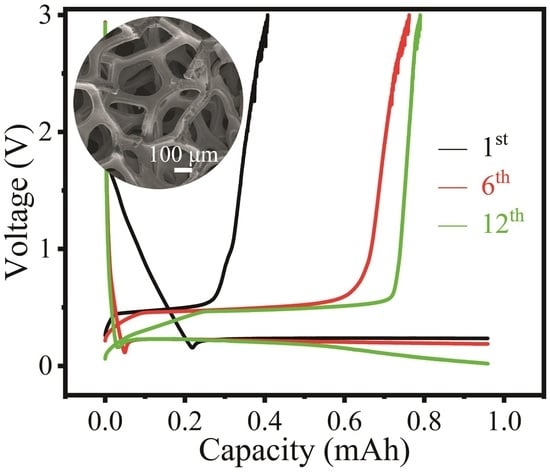
The cycling performance of the Al/3DCu electrode was further evaluated at 21 mA g−1. An Al/3DCu electrode with 12 mg Al obtained in air delivered a first discharge (to 0 V) capacity of 5.7 mAh (475 mAh g−1 vs. 993 mAh g−1 of LiAl, black line in Figure 4g) in a coin cell. This electrode already exceeds the theoretical specific capacity of a carbon electrode (372 mAh g−1). However, an Al/3DCu electrode with 10.5 mg Al obtained in an argon-filled glovebox delivered an even higher first discharge (to 0 V) capacity of 10.3 mAh (981 mAh g−1 vs. 993 mAh g−1 of LiAl, red line in Figure 4g). This demonstrates that the surface passivation of Al in air may strongly hinder electrochemical alloying. It is therefore highly advisable to ensure inert conditions throughout the assembly process.
The cell maintained its performance over 12 cycles of 7 h each with a depth of discharge of approximately 1 mAh per cycle. The reason for the smaller charging capacity of the first cycle could be the formation of an SEI on the Al/3DCu electrode and the battery activation. The Coulombic efficiency was 82.4% after 12 cycles (Figure 4h). These performance indicators suggest the stable reversibility of Al/3DCu as electrode material in LIBs. Encouragingly, the alloying process during discharge of the battery did not result in visible powder shedding on the surface (Figure 5a–d) or interface (Figure 5e–h) of the LixAl/3DCu electrode. The formed LixAl alloy remains intimately attached to the 3DCu skeleton and exhibits good interfacial stability, convincingly illustrating volume expansion tolerance (Figure 5e–h vs. Figure 3o–r). After the charging process, i.e., the release of Li+ from the LixAl alloy, the Al coating remains compactly attached to 3DCu (Figure 5i–p and Figure S13b,c). It is worth pointing out that the angle of the sample taping is not perpendicular. Therefore, the Al signals shown are those of the surface and not of detached Al (Figure 5g,o).
Moreover, the achieved capacity corresponds to a quantitative alloying of the available Al to LiAl. We therefore also tested an Al/3DCu electrode with 2.6 times the loading (27.5 mg Al). This corresponds to about 30% of a solid Al electrode with the same dimensions. Substantially higher loadings led to a shedding of Al. With this higher loading, the specific capacity was 19.5 mAh (709.7 mAh g−1, Li0.71Al); i.e., it did not increase linearly with the available Al. To check whether this is a matter of diffusion or available space for LiAl formation, the latter is calculated. The used 3DCu foam has a total volume of 0.03 cm × 1.13 cm2 = 0.034 cm3 and weighs 64.2 mg. The specific density of the 3DCu mesh is thus 1.89 g cm−3, which corresponds to 21% of the density of bulk copper (8.92 g cm−3). Taking into account that LiAl has about twice the molar volume of Al, theoretically, half of the empty volume, i.e., 0.013 cm3, can be filled with Al (density 2.70 g cm−3) without losing the advantage of the special electrode morphology. This highest functional loading corresponds to 36 mg Al. Since the Al mass used was lower, the diffusion and accessibility of the inner regions of the pores throughout the process appear to be the limiting factors for alloying the Al electrode.

3. Materials and Methods

3.1. Chemicals and Materials

[BMIm]Br (99%) and [HMIm]Br (99%) were purchased from io-li-tec. [BMIm]Cl (99%) was purchased from abcr GmbH. AlCl3 (anhydrous, 99.985%) was supplied by Alfa Aesar. An electrolyte with 1 mol L–1 lithium hexafluorophosphate (LiPF6) dissolved in ethylene carbonate and diethyl carbonate hybrid solvent (volumetric ratio VEC:VDEC = 1:1) and 3DCu (0.3 × 200 × 300 mm3, weight 35.2 g, pore size 0.23 mm, surface density 600 g m–2) were purchased from Guangdong Canrd New Energy Technology Co., Ltd., Guangzhou, China, Li foils (about 15.8 mm diameter) were obtained from Riedel de Haën. The Cu foil (12 μm thickness, for battery negative collector) was laboratory grade. WhatmanTM glassy fiber (GF) and 3DCF were purchased from Sigma Aldrich and FuelCellStore separately. A coin cell shell (CR2032) with a stainless steel spring and spacer (1.0 mm thickness, about 16 mm diameter) was purchased from Guangdong Canrd New Energy Technology Co., Ltd. Prior to use, [BMIm]Br and [HMIm]Br were dried at 110 °C using a dynamic vacuum overnight. Other chemicals were applied without further purification or treatment in the manner received.

3.2. Material Synthesis

3.2.1. Preparation of the Room Temperature ILs

AlCl3 and [BMIm]Br [BMIm]Cl, or [HMIm]Br in the molar ratio of nAlCl3:nIL = 2:1 were weighed in a glass flask inside an argon-filled glovebox (H2O and O2 levels of less than 1.2 ppm). Dissolution was achieved by stirring at room temperature 4 h or overnight.

3.2.2. Preparation of an Al/3DX (X = Cu, CF) Electrode for Lithium-Ion Batteries

Al was electrodeposited on 3DCu stripes (20 mm × 14 mm), disk (12 mm diameter) or 3DCF stripes (22 mm × 12 mm) with a three-electrode system in a sealed cell under a VMP-3 model of Biologic SAS controlled by EC-LAB electrochemistry software (Bio-Logic Science Instruments, Orlando, FL, USA). The electrolyte and Al source was [BMIm]Br·2AlCl3. In all mass calculation of the active substance Al, the mass of the 3DCu or 3DCF substrate has already been subtracted. The mass loading of Al on 3DCu was about 0.71 to 11.9 mg cm−2 at −1.70 V and 4.4 to 49 mg cm−2 at −1.85 V. The Al loading on 3DCF was about 1.4 mg cm−2 at −1.85 V.

3.3. Instrumentation and Characterization

3.3.1. Electrochemical Measurements

All electrochemical experiments were carried out with a three-electrode system in a sealed cell under a VMP-3 model of Biologic SAS controlled by EC-LAB Electrochemistry software. Before all the measurements, all electrodes were washed with ethanol and dried, firstly.
The cyclic voltammogram (CV) was tested using a three-electrode setup (Wuhan Corrtest Instruments Corp. Ltd., Wuhan, China), which consisted of a glassy carbon rod (GC, 3 mm diameter, working electrode), a cylindrical platinum wire (Pt, 99.95%, 0.5 mm diameter, counter electrode), and a platinum plate (99.95%, 10 × 10 × 0.1 mm, reference electrode).
The electrodeposition of Al was carried out by a potentiostatic program at various temperatures and potentials. For Al deposition, the working, counter, and reference electrodes are, respectively, a Cu foil (15 mm × 10 mm × 12 μm, for the negative collector of the battery, cleaned with ethanol only), a Pt plate (as above), and a cylindrical Pt wire (as above). In experiments with alternative substrates, only the working electrode was replaced by 3DCu or 3DCF; the rest of the settings remained unchanged. Caution! During electrodeposition, halogen gas may be generated, which is also partially dissolved in the IL.
CV and electrodeposition experiments at different temperatures and potentials were performed within a sealed cell (Wuhan Corrtest Instruments Corp. Ltd., Wuhan, China), including filling with the solutions in a glovebox. After electrodeposition, the samples were cleaned with dichloromethane and ethanol, dried in a vacuum oven and stored in an argon-filled glovebox before further analysis and characterization. For the Al/3DCu electrode, similar cleaning was also performed in the inner argon-filled glovebox.
The electrochemical impedance spectra (EIS) of [BMIm]Br·2AlCl3 were measured using a coin-type (CR2032) battery, assembled in an argon-filled glovebox, in the frequency range of 100 mHz to 1 MHz at a perturbation voltage of 10 mV. The thickness of the battery was measured using a micrometer gauge. The ionic conductivity (σ) was calculated according to the equation σ = L/(R·S). R represents the bulk resistance, obtained by the simulation according to the equivalent circuit. L and S are, respectively, the thickness and the bottom area of the battery.
The Al/3DCu stripe was punched into 12 mm diameter discs using a precision disc cutter (MSK-T-06, MTI Corporation, America). The Al/3DCu electrode was then pressed gently (Specac presses, England, about 5.5 kg cm−2) to prevent puncturing the GF separator. The Al/3DCu electrode and Li plate by pressing the adhesive on the stainless steel spacer were assembled in the glovebox into coin-type (CR2032) batteries applying a GF separator and the above-mentioned electrolyte to test their electrochemical performance, including open circuit voltage (OCV), CV and EIS, separately. The Al/3DCu||Li batteries employing a double-layered GF separator were rested for 12 h before testing discharge capacity and cycling stability. The first discharge capacity was determined by discharging to 0 V at 21 mA g–1 with Al loading of about 12 mg. The cycling stability tested by discharging for 7 h and then charging to 3 V at 21 mA g–1 with Al loading of about 6.5 mg. For the characterization of the morphology before and after cycling, Al/3DCu||Li batteries were discharged to 0 V at 4.2 mA g–1 with Al loading of about 55.5 mg or discharged to 0 V and then charged to 3 V at 21 mA g–1 with Al loading of about 7.5 mg, respectively. Cycled Al/3DCu electrodes were then removed from Al/3DCu||Li batteries, cleaned with diethyl carbonate, and stored in a glove box.

3.3.2. Powder X-ray Diffraction (PXRD)

PXRD was performed under an Empyrean diffractometer (PAN-analytical) at 296(1) K fitted with a curved Ge(111) monochromator in Bragg–Brentano geometry with Cu-Kα1 radiation (λ = 154.0598 pm). Cycled Al/3DCu electrodes were tested using an airtight sample table and polyimide film wrapped around the electrode.

3.3.3. Nuclear Magnetic Resonance (NMR) Spectroscopy

NMR spectra were tested using a Bruker Avance Neo 300 MHz spectrometer with a 5 mm high-resolution probe. A capillary filled with DMSO-d6 was added to this sample to make sure field-frequency lock. The transmitter frequency was 75.4752953 MHz for 13C NMR and 78.204451 MHz for 27Al NMR. In both cases, 512 scans with a 5 s relaxation delay were recorded. 13C NMR spectra were recorded relative to tetramethylsilane and the 27Al NMR spectra relative to an aqueous solution of Al(NO3)3.

3.3.4. Scanning Electron Microscopy (SEM) and Energy-Dispersive X-ray (EDX) Analysis

The samples were glued on carbon adhesive (laboratory grade). Afterwards, the carbon adhesive was fixed on a sample holder. SEM images were photographed using a field emission scanning electron microscope (FESEM, Zeiss Gemini 500, Germany and Hitachi SU8020, Japan). The composition of the samples was probed by semi-quantitative EDX analysis applying a Zeiss Gemini 500 instrument fitted with an Oxford EDX detector or Oxford Silicon Drift Detector (SDD) X-MaxN on Hitachi SU8020. Cycled Al/3DCu electrodes were cut in a glovebox and tested using an airtight sample holder.

3.3.5. Infrared (IR) Spectroscopy

Around a 0.3 mL sample was dripped on the sample table for the measurements. Vibrational spectra were tested with a Bruker Vertex 70 FTIR spectrometer (Germany) using attenuated total reflection (ATR) accessory in the radiation range of 500 ≤ ≤ 4000 cm–1. The program OPUS was used for the data analysis.

4. Conclusions

In conclusion, the electrochemical behavior, ionic conductivity and activation energy of the mixed-halide IL [BMIm]Br·2AlCl3 have been studied in detail. IL-based electrodeposition of Al can be achieved at lower voltage than for the pure chloride IL. The morphology of the deposited Al layer depends on the voltage, temperature and substrate type but little on the specific imidazolium cation. The deposition of Al on a 3DCu substrate leads to a binder-free Al/3DCu electrode, which is not only mechanically stable but also buffers the large volume changes during alloying and dealloying with Li in a rechargeable LIB. The high degree of reversibility thus achieved for the electrode processes enables stable operation of the LIB. In contrast to many nanostructured electrodes, the amount of Al reached 30% of a solid Al electrode. Alloying to Li0.71Al (5 mg Li in 27.5 mg Al) corresponds to a capacity of 709.7 mAh g–1 (Al based), clearly exceeding the theoretically possible capacity of carbon electrodes currently used in LIBs (372 mAh g–1) [2]. The volume capacity, which is of interest with respect to the space available in a coin cell, is 1.92 Ah cm–3 for the here presented Al-LIB and about 0.74 Ah cm–3 for an LIB with carbon electrode. The concept of curved 3D electrodes provides a good compromise between diffusion kinetics and the total amount of Al available in a coin cell and appears promising for application.

Supplementary Materials

The following supporting information can be downloaded at: https://www.mdpi.com/article/10.3390/batteries9010037/s1, Figure S1: (a) The comparison of the [BMIm]Br and AlCl3 used in this paper with the standard XRD patterns (the insertion is the molecular structure of [BMIm]Br). (b) Photograph of the IL [BMIm]Br·2AlCl3 at room temperature; Figure S2: (a) EIS of the IL [BMIm]Br·2AlCl3 (inset: the equivalent circuit for the simulation). (b) The linear fitting curve of activation energy; Figure S3: Synopsis of the CVs of [BMIm]Br·2AlCl3 and [BMIm]Cl·2AlCl3 at different scan rates and temperatures; Figure S4: Time current curve via potentiostatic electrolysis for electrodeposited Al at −1.70 V and 70 °C after about 2.5 h; Figure S5: PXRD pattern of Al electrodeposited on Cu foil from of the IL [BMIm]Br·2AlCl3 at chosen conditions; Figure S6: (a–h) SEM images (increasing magnification) of electrodeposited Al on Cu foil substrate at −1.70 V and 70 °C after about 2.5 h; Figure S7: EDX mappings and signals of all elements of the Cu and Al distribution of the Al layer electrodeposited at −1.70 V (a–d) or −1.85 V (e–g) at 70 °C; Figure S8: (a) Photograph of the [BMIm]Br·2AlCl3 solution at room temperature after about 2.5 h of Al electrodeposition at −1.70 V and 70 °C. Comparison of pristine [BMIm]Br·2AlCl3 (black line) and the ILs after about 2.5 h of Al electrodeposition at −1.70 V and 70 °C (red line). (b) Corresponding 13C NMR spectra (the insertion is the labeling of different carbon atoms of [BMIm]Br). (c) 27Al NMR spectra; Figure S9: (a) FT–IR spectrum in the range of 1000 cm−1 ≤ 4000 cm−1 of [HMIm]Br used in this paper (the insertion is the molecular structure of [HMIm]Br). (b) Photograph of [HMIm]Br·2AlCl3 ILs solution at room temperature; Figure S10: (a) CV of [HMIm]Br·2AlCl3 at a scan rate of 50 mV s−1 and different temperatures; inset: photograph of the Cu foil substrate after 7 h of Al electrodeposition at −1.70 V and 90 °C. (b) Comparison of the PXRD pattern of the coated electrode. SEM images of the Al layers with enlarged details (inset) that were electrodeposited at (c) −1.70 V or (d) −1.85 V at 90 °C within 7 h; Figure S11: Cross-sectional SEM image of the Al layer electrodeposited at −1.85 V and 90 °C (skeleton structure of 3DCu indicated with red dotted lines, the thickness of Al layer is about 12–19 μm); Figure S12: (a–b) SEM images and (c–d) EDX mappings of all elements of the C distribution of 3DCF. (e) PXRD pattern comparison. (f–i) SEM images and (j–l) EDX mappings of all elements of the C and Al distribution of the loaded Al/3DCF electrode electrodeposited at −1.85 V at 90 °C; Figure S13: (a) PXRD pattern comparison of discharged to 0 V at 4.2 mA g−1 and charged to 3 V electrode at 21 mA g−1. (b–c) SEM images (increasing magnification) of an Al/3DCu electrode charged to 3 V at 21 mA g−1; Table S1: Measured data and corresponding calculated values of ionic conductivity of the IL [BMIm]Br·2AlCl3; Table S2: Based on the calculated ionic conductivity (σ) of the IL [BMIm]Br·2AlCl3, the relevant parameters used to fit the activation energy Ea are calculated according to the Equations (S1)–(S3).

Author Contributions

M.R. gave advice for the experiment and participated in the analysis of results, discussing and writing the paper. P.C. participated in the experimental design, synthesized the samples, carried out the characterizations and wrote the manuscript. All authors have read and agreed to the published version of the manuscript.

Funding

Peng Chen was supported by the China Scholarship Council (CSC).

Data Availability Statement

The data that support the findings of this study are available from the corresponding author upon reasonable request.

Acknowledgments

We gratefully acknowledge the assistance of Tobias Pietsch for recording the NMR spectra and Yiran Wang and Dongqi Li for the SEM and EDX measurements. We thank Stefan Kaskel for access to the Biologic device.

Conflicts of Interest

The authors declare no conflict of interest.

References

  1. Sun, Y.; Liu, N.; Cui, Y. Promises and Challenges of Nanomaterials for Lithium-Based Rechargeable Batteries. Nat. Energy 2016, 1, 16071. [Google Scholar] [CrossRef]
  2. Au, M.; McWhorter, S.; Ajo, H.; Adams, T.; Zhao, Y.; Gibbs, J. Free Standing Aluminum Nanostructures as Anodes for Li-Ion Rechargeable Batteries. J. Power Source 2010, 195, 3333–3337. [Google Scholar] [CrossRef]
  3. Tan, D.; Chen, P.; Wang, G.; Chen, G.; Pietsch, T.; Brunner, E.; Doert, T.; Ruck, M. One-Pot Resource-Efficient Synthesis of SnSb Powders for Composite Anodes in Sodium-Ion Batteries. RSC Adv. 2020, 10, 22250–22256. [Google Scholar] [CrossRef]
  4. Lee, S.H.; Deshpande, R.; Parilla, P.A.; Jones, K.M.; To, B.; Mahan, A.H.; Dillon, A.C. Crystalline WO3 Nanoparticles for Highly Improved Electrochromic Applications. Adv. Mater. 2006, 18, 763–766. [Google Scholar] [CrossRef]
  5. Ru, Y.; Zheng, S.; Xue, H.; Pang, H. Different Positive Electrode Materials in Organic and Aqueous Systems for Aluminium Ion Batteries. J. Mater. Chem. A 2019, 7, 14391–14418. [Google Scholar] [CrossRef]
  6. Li, S.; Niu, J.; Zhao, Y.C.; So, K.P.; Wang, C.; Wang, C.A.; Li, J. High-Rate Aluminium Yolk-Shell Nanoparticle Anode for Li-Ion Battery with Long Cycle Life and Ultrahigh Capacity. Nat. Commun. 2015, 6, 7872. [Google Scholar] [CrossRef] [PubMed] [Green Version]
  7. Xia, G.; Zhang, H.; Liang, M.; Zhang, J.; Sun, W.; Fang, F.; Sun, D.; Yu, X. Unlocking the Lithium Storage Capacity of Aluminum by Molecular Immobilization and Purification. Adv. Mater. 2019, 31, 1901372. [Google Scholar] [CrossRef]
  8. Su, C.J.; Hsieh, Y.T.; Chen, C.C.; Sun, I.W. Electrodeposition of Aluminum Wires from the Lewis Acidic AlCl3/Trimethylamine Hydrochloride Ionic Liquid without Using a Template. Electrochem. Commun. 2013, 34, 170–173. [Google Scholar] [CrossRef]
  9. Li, B.; Fan, C.; Chen, Y.; Lou, J.; Yan, L. Pulse Current Electrodeposition of Al from an AlCl3-EMIC Ionic Liquid. Electrochim. Acta 2011, 56, 5478–5482. [Google Scholar] [CrossRef]
  10. Su, C.J.; Hsieh, Y.T.; Fong, J.D.; Chang, C.C.; Sun, I.W. Template Free Synthesis of Beaded Aluminium Sub-Microwires: Via Pulse Potential Electrodeposition. RSC Adv. 2016, 6, 75054–75057. [Google Scholar] [CrossRef]
  11. Wang, H.; Tan, H.; Luo, X.; Wang, H.; Ma, T.; Lv, M.; Song, X.; Jin, S.; Chang, X.; Li, X. The Progress on Aluminum-Based Anode Materials for Lithium-Ion Batteries. J. Mater. Chem. A 2020, 8, 25649–25662. [Google Scholar] [CrossRef]
  12. Tong, X.; Zhang, F.; Ji, B.; Sheng, M.; Tang, Y. Carbon-Coated Porous Aluminum Foil Anode for High-Rate, Long-Term Cycling Stability, and High Energy Density Dual-Ion Batteries. Adv. Mater. 2016, 28, 9979–9985. [Google Scholar] [CrossRef] [PubMed]
  13. Hudak, N.S.; Huber, D.L. Size Effects in the Electrochemical Alloying and Cycling of Electrodeposited Aluminum with Lithium. J. Electrochem. Soc. 2012, 159, A688–A695. [Google Scholar] [CrossRef]
  14. Chen, P.; Richter, J.; Wang, G.; Li, D.; Pietsch, T.; Ruck, M. Ionometallurgical Step-Electrodeposition of Zinc and Lead and Its Application in a Cycling-Stable High-Voltage Zinc-Graphite Battery. Small 2021, 17, 2102058. [Google Scholar] [CrossRef] [PubMed]
  15. Zhang, L.P.; Yu, X.J.; Dong, Y.H.; Li, D.G.; Zhang, Y.L.; Li, Z.F. Electrodeposition of Aluminum on Magnesium from Ionic Liquid (EMIM)Br-AlCl3. Trans. Nonferrous Met. Soc. China 2010, 20, s245–s248. [Google Scholar] [CrossRef]
  16. Wang, D.; Zhong, X.; Liu, F.; Shi, Z. Electrodeposition of Aluminum from AlCl3-1-Ethyl-3-Methylimidazolium Fluoride. Int. J. Electrochem. Sci. 2018, 14, 9482–9489. [Google Scholar] [CrossRef]
  17. Wen, X.; Liu, Y.; Xu, D.; Zhao, Y.; Lake, R.K.; Guo, J. Room-Temperature Electrodeposition of Aluminum via Manipulating Coordination Structure in AlCl3 Solutions. J. Phys. Chem. Lett. 2020, 11, 1589–1593. [Google Scholar] [CrossRef]
  18. Ahmed, E.; Breternitz, J.; Groh, M.F.; Isaeva, A.; Ruck, M. [Sb7Se8Br2]3+ and [Sb13Se16Br2]5+—Double and Quadruple Spiro Cubanes from Ionic Liquids. Eur. J. Inorg. Chem. 2014, 2014, 3037–3042. [Google Scholar] [CrossRef]
  19. Wang, H.; Gu, S.; Bai, Y.; Chen, S.; Zhu, N.; Wu, C.; Wu, F. Anion-Effects on Electrochemical Properties of Ionic Liquid Electrolytes for Rechargeable Aluminum Batteries. J. Mater. Chem. A 2015, 3, 22677–22686. [Google Scholar] [CrossRef]
  20. Chen, P.; Wang, X.; Li, D.; Pietsch, T.; Ruck, M. A Kinetically Superior Rechargeable Zinc-Air Battery Derived from Efficient Electroseparation of Zinc, Lead, and Copper in Concentrated Solutions. ChemSusChem 2022, 15, e202200039. [Google Scholar] [CrossRef]
  21. McMahon, B.W.; Yu, J.; Boatz, J.A.; Anderson, S.L. Rapid Aluminum Nanoparticle Production by Milling in NH3 and CH3NH2 Atmospheres: An Experimental and Theoretical Study. ACS Appl. Mater. Interfaces 2015, 7, 16101–16116. [Google Scholar] [CrossRef] [PubMed]
  22. Straumanis, M.E.; Yu, L.S. Lattice Parameters, Densities, Expansion Coefficients and Perfection of Structure of Cu and of Cu—In α Phase. Acta Crystallogr. Sect. A Cryst. Phys. Diffr. Theor. Gen. Crystallogr. 1969, 25, 676–682. [Google Scholar] [CrossRef] [Green Version]
  23. Witt, W. Absolute Präzisionsbestimmung von Gitterkonstanten an Germanium- und Aluminium-Einkristallen mit Elektroneninterferenzen. Z. Für Nat. A 1967, 22, 92–95. [Google Scholar] [CrossRef]
  24. Chen, S.; Yang, X.; Zhang, J.; Ma, J.; Meng, Y.; Tao, K.; Li, F.; Geng, J. Aluminum−lithium Alloy as a Stable and Reversible Anode for Lithium Batteries. Electrochim. Acta 2021, 368, 137626. [Google Scholar] [CrossRef]
  25. Hamon, Y.; Brousse, T.; Jousse, F.; Topart, P.; Buvat, P.; Schleich, D.M. Aluminum Negative Electrode in Lithium Ion Batteries. J. Power Source 2001, 97–98, 185–187. [Google Scholar] [CrossRef]
Figure 1. Electrochemical properties of [BMIm]Br·2AlCl3. (a) Magnified EIS. (inset: the equivalent circuit for simulation). (b) Temperature dependence of the ionic conductivity. (c) CV at 70 °C and different scan rates. (d) CV at a scan rate of 50 mV s−1 and different temperatures. (e) CV at 70 °C and 25 mV s−1 (firstly scanning toward the negative potential).
Batteries 09 00037 g001
Figure 2. (a) Photograph of the Cu foil substrate after 2.5 h of Al electrodeposition at –1.70 V and 70 °C. SEM images or with enlarged details (inset) of the Al layer electrodeposited at –1.70 V (b), –1.85 V (c) at 70 °C or –1.85 V at 90 °C (df).
Batteries 09 00037 g002
Figure 3. (a) Photograph, SEM images (enlarged details as inset) and EDX mappings of all elements of the Cu distribution of the pristine 3DCu substrate. (b) PXRD patterns comparison. (c) Photograph of Al/3DCu electrode electrodeposited at –1.70 V and 90 °C. Surface (df,kn) and cross-sectional (gj,or) SEM images (enlarged details as inset and skeleton structure of 3DCu indicated with red dotted lines) and EDX mappings of all elements of the Cu and Al distribution of the Al layer electrodeposited at –1.70 V (dj) or –1.85 V (kr) and 90 °C.
Batteries 09 00037 g003
Figure 4. (a) Working principle of the Al/3DCu||Li battery. The electrochemical performance of the Al/3DCu electrode electrodeposited at −1.70 V (b,df) or –1.85 V (c,g,h) and 90 °C. (b) The stability curve of the open circuit voltage. (c) PXRD pattern comparison of discharged to 0 V at 4.2 mA g−1 and charged to 3 V electrode at 21 mA g−1. (d) CV comparison between three cycles at 0.1 mV s−1 and (e) different scan rate. (f) The EIS comparison between a fresh battery after about 4.7 h rest and the same battery after one CV cycle at 0.05 mV s−1 (inset: the equivalent circuit for the simulation). (g) Galvanostatic first discharge curve to 0 V at 21 mA g−1. (h) Galvanostatic discharge–charge profiles for selected cycles at 21 mA g−1.
Batteries 09 00037 g004
Figure 5. (ad,il) The surface and cross-sectional (eh,mp) morphology stability of the Al/3DCu electrode electrodeposited at –1.85 V and 90 °C firstly discharged (ah) at 4.2 mA g−1 and charged (ip) at 21 mA g−1. (a,i) Photograph (b,e,j,m) SEM images and (f,n) EDX mappings of all elements of (c,d,g,h,k,l,o,p) the Al and Cu distribution of electrode.
Batteries 09 00037 g005
Disclaimer/Publisher’s Note: The statements, opinions and data contained in all publications are solely those of the individual author(s) and contributor(s) and not of MDPI and/or the editor(s). MDPI and/or the editor(s) disclaim responsibility for any injury to people or property resulting from any ideas, methods, instructions or products referred to in the content.

