1. Introduction
In recent years, the demand for renewable energy, such as solar energy, tidal energy and wind energy, has grown sharply. However, these renewable energies are limited by weather and geographical conditions, which lead to an increased need for energy storage devices. With the development of energy storage devices, safety concerns are increasing. It is necessary to develop energy storage technology that is safer, more sustainable and more environmentally friendly [
1,
2]. Aqueous rechargeable batteries exhibit high safety, low cost and environmental friendliness, which make them a promising candidate for large-scale grid energy storage [
3,
4,
5,
6,
7,
8]. However, the insufficient energy density of aqueous ion batteries derived from narrow electrochemical windows impedes their further applications. Recently, electrode materials of aqueous batteries for various cationic electrochemical systems (like Li
+, Zn
2+, K
+, Na
+ or mixed cations) as well as new electrolytes with a wider window of electrochemical stability have been developed [
9]. To increase the energy level, aqueous multivalent systems beyond Li
+, such as Zn
2+, Cu
2+ and Al
3+, have recently attracted much attention owing to their multiple electron transfers. Among them, copper metal manifests a great potential for aqueous batteries due to its low price, noble reaction potential (0.34 V) versus standard hydrogen electrode (SHE), high theoretical specific capacity (844 mAh g
−1 and 7558 mAh cm
−3), abundant in reserves and chemical stability [
10]. Copper anode has almost no dendrite production in aqueous electrolytes, which is a benefit in solving safety concerns and extending cycle life [
11].
Up to now, only a few copper ion storage materials for Cu-ion batteries have been reported. Most of them are conversion type materials, such as S [
12], CuS [
13], CuS
0.5Se
0.5 [
14], Se [
15,
16], Bi
2Se
3 [
17] and Te [
18]. X. Ji and coworkers reported a four electron sulfur electrode which undergoes a sequential conversion of S↔CuS↔Cu
2S [
12]. The sulfur electrode may exhibit the highest specific capacity among various solid electrodes with an extremely low extent of polarization [
12]. J. Shu and coworkers load sulfur into laser induced graphene and convert it into CuS by a pre-discharge process [
13]. A reversible conversion between CuS and Cu
2S occurs during the subsequent cycles [
13]. Different from electrochemical conversion, L. Li and coworkers prepared CuS nanosheet arrays on carbon cloth directly via a hydrothermal reaction followed by an anion-exchange process [
13]. CuS nanosheet arrays are capable of reversible transit from CuS to Cu
7S
4 and to Cu
2S through the redox of Cu
2+/Cu
+, thus an energetic aqueous copper ion system is achieved [
13]. Considering the multiple phase conversion during cycling and poor conduction, CuS
1−xSe
x is synthesized by an anion exchange method [
14]. The anion substitution of S by Se inhibits the phase conversion and improves the electron and ion transfer [
14]. Sulfur based cathodes always suffer from poor electrical conductivity, thus the sibling of S, selenium, is coupled with the copper anode [
15,
16]. J. Shu and coworkers reported a two-step conversion reaction between Se, CuSe and Cu
2Se [
15]. L. Qu and coworkers reported a more complicated conversion process in which CuSe, Cu
3Se
2, Cu
2−xSe and Cu
2Se are the discharge products at various discharge stages [
16]. Although the electrochemical reactions during cycling are different, the final discharge product is Cu
2Se, which can deliver a four-electron redox reaction, providing a high capacity with long cycle life [
15,
16]. The asymmetric Cu–Te alloying phase–conversion process of tellurium cathode occurs during cycling, which is accompanied by an irreversible side reaction of tellurium oxidation [
18]. After introduction of poly(ethylene glycol) (PEG) molecular chains and l-ascorbic acid additive, the electrolyte solvation structure is tuned and tellurium electrode is protected [
18]. Prussian blue analogues are employed as a Cu-ion intercalation framework, which is a common host for the insertion of multivalent metal ions. When CuFePBA is used as a cathode material, proton and Cu cation co-insert into the cathode framework, which induces a phase transformation process. The proton enhanced kinetics lead to excellent power performance that is comparable to supercapacitors [
19]. MnO
2-Cu cells based on a holistic deposition–dissolution mechanism were investigated, which can be universally adopted for other aqueous batteries [
20].
In these literatures, Prussian blue analogues are the only family that has been reported as intercalation type electrode materials. To extend the choice of Cu
2+ intercalation type materials, we focus on layered vanadium pentoxide. Layered V
2O
5 manifests a typical two-dimensional lamellar crystal structure, which affords ion storage sites between the layers. Its chemical multivalences of vanadium elements maximize intercalated ion numbers and thus provide high theoretical specific capacity. As expected, Li
+ ions can be stored in layered V
2O
5 and the theoretical specific capacity is up to 420 mAh g
−1 [
21,
22]. Layered V
2O
5 also can be employed as a cathode material to store Na
+ ions [
23] and K
+ ions [
24]. Inspired by the storage capability of monovalent alkali ions, layered V
2O
5 were used to accommodate multivalent metal ions, such as Mg
2+ [
25] and Zn
2+ [
26]. Layered V
2O
5 demonstrates the excellent storage capability of Zn
2+ ions and the structure framework remains after long cycles [
27]. It can be clearly seen that no matter monovalent or multivalent metal ions can intercalate into the layered vanadium pentoxide framework.
Herein, layered vanadium pentoxide is employed as a Cu2+ intercalation type material for the first time. Commercial vanadium pentoxide is taken as an example to store copper ions for aqueous batteries. XRD results confirms the V2O5/Cu0.6V2O5·0.2H2O two-phase electrode reaction during cycling. XPS results indicate tetravalent vanadium is generated during discharge, which will be oxidized back to pentavalent vanadium. Stable copper ion storage performance is achieved within a voltage range of 0.02–0.08 V. V2O5 electrodes can remain at about 55 mAh g−1 after 4000 cycles at 1 A g−1. In the comparison of the electrochemical properties of bulk V2O5 and V2O5 nanoribbons, the electrochemical process are similar but the V2O5 nanoribbon electrode shows faster electrochemical kinetics. Our work will inspire applications of layered materials in copper ion storage.
2. Materials and Methods
Commercial V2O5 (99.9%) powder and CuSO4 were purchased from Macklin (Shanghai, China). Hydrogen peroxide (H2O2) (30 wt%) were purchased from Aladdin (Shanghai, China). Aqueous electrolytes were prepared by dissolving 0.5 M CuSO4 in deionized water. Purchased chemicals are used without further treatment. Carbon cloth was purchased from Guangdong Cande New Energy Technology Co., Ltd. (Guangzhou, China).
V
2O
5 nanoribbons were fabricated by a hydrothermal method [
28]. Briefly, 0.008 mol vanadium pentoxide powder was ultrasonically dispersed in 120 mL of deionized water. After 20 mL of hydrogen peroxide (H
2O
2) (30 wt%) was slowly added, the solution became brown–red and was accompanied by a large number of bubbles. The mixture of the solution was magnetically stirred for 30 min, and then transferred to 200 mL of the inner liner of the PTFE reactor. The hydrothermal reactor was then placed in a blast drying oven at a temperature of 240 °C, and the reactor was returned to room temperature after 12 h of reaction. The reaction products were washed several times with deionized water and anhydrous ethanol, and then heated in a drying oven at 100 °C for 4 h.
Carbon cloth current collector was pre-processed by an alkaline treatment [
29]. Purchased clean carbon cloths were soaked in a 15 wt% KOH solution for 4 h, then the soaked cloths were placed in a tube furnace and calcined at 850 °C for 4 h under an inert gas atmosphere. After cooling down to room temperature, the cloth was immersed in 1 M HCl solution for 1 h. The carbon cloth is then washed several times with ultrapure water until no other liquid substances remained on the surface of the carbon cloth. Finally, the carbon cloth was dried in an oven for 12 h.
The structure of the samples before and after the reaction was characterized by X-ray diffraction (XRD, D8 Advance, Bruker, Karlsruhe, Germany). Scanning electron microscopy (SEM) observations were performed on a TDCLS-8010 (Hitachi, Tokyo, Japan). The surface chemistry of the samples before and after the reaction was analyzed by X-ray photoelectronic spectroscopy (XPS, Perkin-Elmer, PHI-1600, Waltham, MA, USA). The ex situ XRD and ex situ XPS were tested after disassembling the coin cells and washing the cycled electrodes.
The electrochemical performance of the battery was tested by assembling a CR2032 coin cell. The working electrodes were prepared according to the commonly used method, in which the cathode slurry was first prepared by mixing the active material (commercial V2O5 powder) with conductive carbon black (Ketjen Black) and polyvinylidene difluoride (PVDF, 5 wt% in N-methylpyrrolidone) binder in a mass ratio of 7:2:1. The slurry was then applied to a clean carbon cloth and dried in a vacuum oven at 70 °C for 12 h. The button cell was assembled from V2O5 cathode material and copper metal anode. The electrolyte was 0.5 M CuSO4 aqueous solution. A glass fiber membrane with a thickness of 0.5 mm was used as a separator. The mass load was 2~3 mg cm−2. The as-prepared batteries were tested on a multi-channel battery test system (LAND CT2001A, Wuhan Bateri Technology Co., Ltd., Wuhan, China) in a voltage range of 0.02 to 0.8 V with galvanostatic charge–discharge test. Cyclic voltammetry (CV) and electrochemical impedance spectroscopy (EIS) of the batteries were tested using an electrochemical workstation (CHI600E) to understand the electrochemical performance of the batteries. As for the EIS test, the frequency range was 0.01~100,000 Hz, and the amplitude was 5 mV. The galvanostatic intermittent titration technique (GITT) was performed using a Neware CT-4008 battery tester. The voltage range was 0.02–0.8 V, the constant current was 0.025 A g−1 and the current pulse lasted for 20 min.
3. Results and Discussion
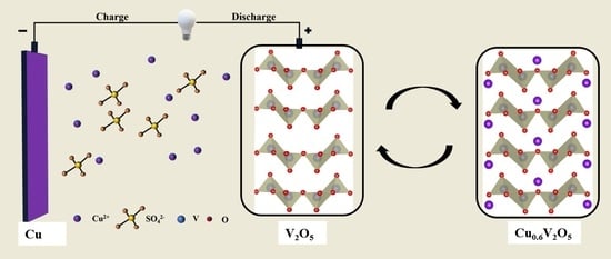
To validate the capability of Cu
2+ intercalation/deintercalation into/from the V
2O
5 framework, V
2O
5 is employed as the cathode material, copper metal as the anode material and 0.5 M CuSO
4 aqueous solution as the electrolyte, as shown in
Figure 1a. Universally V
2O
5 has multiple oxidation states and layered crystal structures that can act as a redox-active cathode framework, which allows for reversible intercalation/decalculation of Cu
2+ ions. In particular, the V
2O
5 crystal structure consists of tetragonal pyramids connected by a V
4O
10 layer structure. Layers are formed with physical van der Waals forces acting on the edges and corners, resulting in a layered structure. The layered V
2O
5 framework can accommodate Cu
2+ ions due to larger opened interlayer spacing of V
2O
5 compared to the radius of Cu
2+ ions. It is reasonably favorable for insertion or extraction of Cu
2+ ions during the electrochemical cycling process [
30].
Figure 1b compares XRD patterns for V
2O
5 powder and V
2O
5 cathode in a full discharged state. The XRD pattern for the commercial V
2O
5 powder can be indexed to a layered structure with a space group of Pmmn, without any impurity peak [
31,
32,
33]. Moreover, the observed derivatization peaks shows characteristic sharpness, which may suggest that the species has a high level of crystallinity. Comparative strong peaks at 15.3°, 20.2°, 21.6°, 26.0°, 32.3°, 34.2°, 41.1°, 44.3°, 47.3°, 48.8° and 51.1° can be identified with the crystal planes (200), (001), (101), (110), (011), (310), (002), (202), (600), (012) and (020), respectively. Moreover, the lattice parameters are a = 11.516, b = 3.5656, c = 4.3727 Å and α = β = γ = 90.0°. In contrast, the XRD pattern of the V
2O
5 cathode in a fully discharged state match well with Cu
0.6V
2O
5·0.2H
2O (JCPDS No. 49-0175). According to inductively coupled plasma (ICP) data, the discharge product can be speculated to be Cu
0.29V
2O
5, which is in accordance with the XRD results. The XRD results confirm successful insertion of copper atoms into the V
2O
5 structure. The intercalated copper ions act as atomic columns which increase the distance between the vanadium layers and facilitate the ionic diffusion. SEM images of the commercial V
2O
5 powder is presented in
Figure S1. It can be observed that most of the unevenly distributed clumps have a particle size ranging from 0.5 to 3 μm.
A full understanding of the charge storage mechanism is a necessary prerequisite for further optimization of the Cu-V
2O
5 system. For this purpose, ex situ XRD measurements were performed to investigate the structure of the V
2O
5 electrode under various stages (
Figure 2a,b). All the XRD peaks matched well with layer structured V
2O
5 (JCPDS no. 41-1426), and there are no diffraction peaks associated with impurities in the samples, which also indicates that the Cu ions were successfully introduced into the V
2O
5 crystal structure (
Figure 2b). With increase in Cu content, the intensities of (001) and (002) diffraction peaks decreased accordingly, indicating that Cu ions induce the lattice distortion of V
2O
5. Meanwhile, with the increase in Cu content, the (001) peak shows a slight shift to the lower angle. This is caused by the increase in the interlayer distance of V
2O
5. Cu has a larger atomic radius. The intercalated Cu ions are expected to exist as pillars between the interlayers, which led to a slight widening of the interlayer spacing along the directions of c-axis. It may lead to an increase in the cell volume. The enlarged interlayer spacing of V
2O
5 with intercalated Cu ions is propitious to the transport of ions [
34]. At the full discharged state, a new peak appears which can be assigned to Cu
0.6V
2O
5·0.2H
2O. After charging, the peak of Cu
0.6V
2O
5·0.2H
2O disappears. The peak of Cu
0.6V
2O
5·0.2H
2O can be observed again at the full discharged state of the second cycle. These results indicate that layered V
2O
5 undergoes a two-phase reaction, between V
2O
5 and Cu
0.6V
2O
5·0.2H
2O, during charge and discharge.
XPS was also used to probe the chemical configurations of V
2O
5 during battery operation. In order to reveal the characteristics of V
2O
5,
Figure 3a,b show Cu 2p and V 2p XPS spectra of the cathode material. Signals of vanadium, oxygen and copper can be observed in the samples before and after the reaction, indicating that Cu ions were successfully introduced into the V
2O
5 lamellar structure (
Figure S2a). For the spectrum of V 2p, the characteristic peaks at 517.45 and 525.0 eV correspond to V
5+, while the peaks at 516 and 523.98 eV correspond to V
4+ [
35,
36]. After discharge, the intensity of V
4+ increases, implying the transformation of V
5+ to V
4+ due to the introduced Cu
2+, as shown in
Figure 3a. The amount of V
4+ increases 28% to the total vanadium after copper insertion. It can be speculated that the discharge product at surface is Cu
0.28V
2O
5. The XPS data are in accordance with XRD and ICP results. Of note is the spectrum of Cu 2p (
Figure 3b), where the satellite peaks at 941.78 and 944 eV as well as the strong satellite peak at 934.83 eV are coherent with the CuO spectra, suggesting the presence of +2 valence Cu in the discharged sample [
29]. Hybridization between Cu 3d and other valence orbitals, especially when the oxygen in the local chemical environment is linked to V or H, and the presence of strong Coulombic interactions between the 3d electrons lead to the appearance of other satellite peaks. Both the pristine and charged electrodes show two typical O 1s signals at approximately 530.1 and 532 eV, corresponding to various V-O coordination of the VO
x layer (
Figure S2b). The introduction of Cu
2+ increases the V
4+ content. The higher electronic conductivity of the Cu inserted V
2O
5 than pristine V
2O
5 can be achieved when V
5+ is reduced to V
4+. The theory of small polaritons can explain the conductive mechanism of the Cu inserted V
2O
5. As the Cu ion enters the layered V
2O
5 structure, the negative charge on the V
4+ counterion and the lattice deformation induced by the Cu
2+ cation are coupled together to produce a smaller polarizer, which may lead to a higher electronic conductivity [
37]. The enhanced electrical conductivity of Cu inserted V
2O
5 may improve the transport efficiency of other metal ions. This may be used as a modification method for V
2O
5 as a cathode material for other metal ion batteries.
Stable cycling and rate performance is able to better understand the electrochemical kinetics by measuring the CV curves of the V
2O
5 cathode at various scan rates of 0.2–1.0 mV s
−1. As illustrated in
Figure 4a, the peak cathode/anode potential voltage is shifted at high scan rates when the electrode polarization becomes more severe. As the scan rate increases, the CV curves maintain a similar shape although the potentials of the reduction and oxidation peak shifts. The relationship between peak current (
i) and scan rate (
v) is
i = a
vb. It can be transformed as log(
i) = b × log(
v) + log(a), where the a and b are coefficient parameters, and b is the slope of log(
i) to log(
v). The b value can be used to distinguish between diffusion-controlled Faraday processes and capacitive processes. If the b value is close to 0.5, the charge/discharge process is dominated by ion diffusion; when the b value is close to 1, the electrochemical process is controlled by pseudocapacitive behavior.
Figure 4b shows the log(
i) versus log(
v) for peaks 1 and 2. The corresponding b values are calculated as 0.90 and 0.74, respectively. It suggests that the electrochemical charge storage process of the Cu//V
2O
5 cell is involved with a combination of ionic diffusion and pseudo-capacitive behaviors, which results in excellent reaction kinetics. The electrochemical kinetics of ion and charge transfer was further investigated by EIS. As shown in
Figure 4c, the Nyquist diagram of the pristine V
2O
5 cathode consists of two parts: a semicircle with depressions in the mid-frequency to high-frequency region, which indicates the charge transfer resistance (R
ct), and a diagonal line in the low-frequency region, which is relevant to the diffusion process in the electrode. The lower R
ct may be due to the presence of tetravalent vanadium ions in the Cu inserted V
2O
5 powder.
The insertion and extraction kinetics of Cu
2+ affect the electrochemical performance of layered V
2O
5 cathode materials. Therefore, it is crucial to understand the diffusion coefficient of Cu
2+ in the active material. The diffusion coefficient of V
2O
5 was calculated using the GITT method. According to the equation [
38]:
where
τ denotes the sustaining time of the current pulse, the mass, molar volume and molar mass of the active material are represented by
mB,
Vm and
MB, respectively, while
S is the contact area between the electrode sheet and the electrolyte, Δ
Es is the potential difference between the termination voltages of the two consecutive relaxation steps and Δ
Et is the difference of the voltages over the entire period of the current pulse minus the IR drop.
Figure 4d presents the GITT profile and the relative
for the first charge/discharge cycle. From the figure, it can be seen that the
of the V
2O
5 cathode reaches a reasonable level in the range of 10
−12 to 10
−10 cm
2 s
−1 [
39,
40,
41].
Figure 5a shows the CV curves of V
2O
5 electrode at a scan rate of 0.2 mV s
−1 between 0.02 and 0.8 V. The CV curves of V
2O
5 electrode for the first three cycles are highly similar, which implies highly reversible electrochemical reactivity of V
2O
5 electrode. There are two oxidation peaks, which are located at 0.23 and 0.5 V. However, no other phase can be observed after Cu
0.3V
2O
5 transforms into V
2O
5. Only slight peak shift can be detected in XRD patterns. It indicates the oxidation peak at 0.5 V is related to a solid solution reaction. The electrochemical properties of V
2O
5 cathode were investigated using 0.5 M aqueous copper sulphate solution as electrolyte and copper foil as the counter/reference electrode.
Figure 5b depicts the charging and discharging profiles of V
2O
5 electrodes at various current densities. Clearly, the charge curve can be divided into two parts. The part below 0.3 V contributes most capacity and the other part is steep. When the current density increases, the shape of V
2O
5 electrode is similar. V
2O
5 electrode shows remarkable multiplicative performance over a wide range of current densities from 0.1–1.5 A g
−1, as shown in
Figure 5c. The charge capacities at 0.1, 0.2, 0.3, 0.5, 1.0 and 1.5 A g
−1 are 100.9, 97.6, 94.9, 88.6, 80.2 and 91.3 mAh g
−1, respectively. As the current rate increases, the plateau of the discharge curve gradually decreases due to the polarization effect and the capacity decreases [
42].
Figure 5d shows the discharge/charge curves of V
2O
5 electrode at 0.5 A g
−1. The initial charge/discharge curve shows a capacity of 93.5 mAh g
−1 with an efficiency of about 97%. To investigate the long cycle capability, the V
2O
5 electrode was charged and discharged at 1.0 A g
−1.
Figure S3 shows galvanostatic discharge/charge curves of various cycles at a current density of 1.0 A g
−1. The shape of the charge and discharge curve looks similar to those at low current densities.
Figure 5e shows the cycling performance at a current density of 1.0 A g
−1. The capacity of V
2O
5 electrode delivers 91.9 mAh g
−1 for the first cycle and remains 55 mAh g
−1 after 4000 cycles. The capacity retention is as high as 60%, which suggests a highly reversible electrochemical process.
The particle size may affect the electrochemical characteristics of the electrode especially when micromaterials and nanomaterials are compared. In batteries, there are two electrochemical behaviors: adsorption activity occurring on the surface and insertion activity occurring internally. Micrometer-sized material manifests a large particle size, thus a small surface area, resulting in less capacitive behaviors associated with surface adsorption. The capacity of the micromaterials is mainly derived from the ion insertion/extraction rather than surface adsorption due to the limited surface area. Nevertheless, the nanomaterial has a small particle size, thus a large surface area, leading to more capacitive behaviors associated with adsorption activity. Consequently, the contribution to the capacity of nanomaterials from surface adsorption is greater compared to micromaterials. Therefore, vanadium pentoxide nanoribbons were also prepared and used as a cathode material to compare their electrochemical properties with micrometer scaled V
2O
5. V
2O
5 nanoribbons were synthesized by a hydrothermal method and the corresponding XRD pattern is shown in
Figure S4. The peaks of (200), (001), (101), (110), (301), (411) and (020) are located at 15.4°, 20.3°, 21.7°, 26.1°, 31.1°, 45.5° and 51.2°, respectively. All these reflections observed can be attributed to layered V
2O
5 with a space group of Pmmn, indicating the successful synthesis of V
2O
5. The XRD results confirm that the phase of the hydrothermal product is the same as bulk V
2O
5.
Figure S5 shows the low and high magnification SEM images of V
2O
5 nanoribbons. The as-prepared V
2O
5 powder exhibits an ultralong nanoribbon morphology whose length is over one hundred micrometers.
After the phase and the particle size are confirmed, the electrochemical properties of the nano and bulk V
2O
5 are compared. The GCD curves of the commercial and nanoribbon V
2O
5 are compared in
Figure S6. The shape of V
2O
5 nanoribbons and bulk V
2O
5 are similar, indicating a similar electrochemical process during cycling. The plateau of V
2O
5 nanoribbon electrode is more distinct, which may be derived from its nanostructure, which improves its electrochemical kinetics.
Figure S7 shows the cycle performance of V
2O
5 nanoribbons and bulk V
2O
5 electrodes at 1.0 A g
−1. The V
2O
5 nanoribbon electrode delivers 70.5 mAh g
−1 for the first cycle and the capacity increases in the few cycles. The capacity increase can be ascribed to an activation process, which also can be found during cycling of bulk V
2O
5 electrodes. After 4000 cycles, the V
2O
5 nanoribbon remains 68.6 mAh g
−1 and corresponds to 97.3% compared to the specific capacity of the initial cycle. The higher capacity and capacity retention suggest the advance of nanometer sized V
2O
5 electrodes, which may be attributed to the shortened ion diffusion path.
Figure S8 compares the rate performances of bulk and nanoribbon V
2O
5 electrodes. The charge capacities are 112.7, 110.4, 102, 91.5, 80.8 and 71.7 mAh g
−1 at 0.1, 0.2, 0.3, 0.5, 1.0 and 1.5 A g
−1, respectively, which are higher than those of bulk V
2O
5 electrodes.


