Review

Conductive Metal–Organic Frameworks for Rechargeable Lithium Batteries

College of Physics Science and Technology, Kunming University, Kunming 650214, China
*
Author to whom correspondence should be addressed.
These authors contributed equally to this work.
Batteries 2023, 9(2), 109; https://doi.org/10.3390/batteries9020109
Submission received: 23 November 2022 / Revised: 16 January 2023 / Accepted: 31 January 2023 / Published: 3 February 2023
(This article belongs to the Special Issue Electrode Materials for Rechargeable Lithium Batteries)

Abstract

:
Currently, rechargeable lithium batteries are representative of high-energy-density battery systems. Nevertheless, the development of rechargeable lithium batteries is confined by numerous problems, such as anode volume expansion, dendrite growth of lithium metal, separator interface compatibility, and instability of cathode interface, leading to capacity fade and performance degradation of batteries. Since the 21st century, metal–organic frameworks (MOFs) have attracted much attention in energy-related applications owing to their ideal specific surface areas, adjustable pore structures, and targeted design functions. The insulating characteristics of traditional MOFs restrict their application in the field of electrochemistry energy storage. Recently, some teams have broken this bottleneck through the design and synthesis of electron- and proton-conductive MOFs (c-MOFs), indicating excellent charge transport properties, while the chemical and structural advantages of MOFs are still maintained. In this review, we profile the utilization of c-MOFs in several rechargeable lithium batteries such as lithium-ion batteries, Li–S batteries, and Li–air batteries. The preparation methods, conductive mechanisms, experimental and theoretical research of c-MOFs are systematically elucidated and summarized. Finally, in the field of electrochemical energy storage and conversion, challenges and opportunities can coexist.

1. Introduction

High-energy density and long working lifetime are the permanent pursuits for rechargeable batteries [1,2,3,4,5,6]. Currently, rechargeable lithium batteries, particularly lithium-ion batteries (LIBs), have been commercialized on a large scale, ranging from small electronic devices such as power banks and cameras to large mobile devices such as electric vehicles and aircraft [7,8,9,10]. Although LIB technology is considered one of the most promising energy storage systems owing to its high energy density and good lifespan [11], LIBs require optimization in several aspects, such as the heat resistance of LIB diaphragms at high temperatures, the life cycle of LIBs at low temperatures, and the recovery of lithium from discarded LIBs to protect the environment [12,13,14]. Batteries such as Li–S and Li–air have gained popularity. Li–S batteries are environmentally friendly and safe, but they have several inherent problems such as the shuttle effect and volume expansion during operations [15,16]. Li–air batteries exhibit ultra-high energy density; however, the battery lifespan is still unsatisfactory [17,18]. To develop good rechargeable lithium batteries, research on advanced materials is essential.
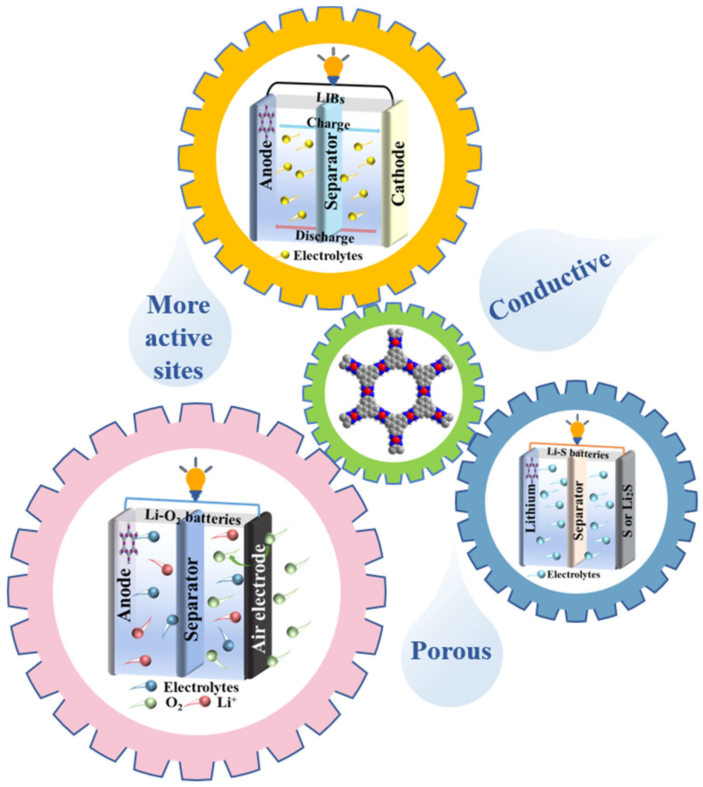
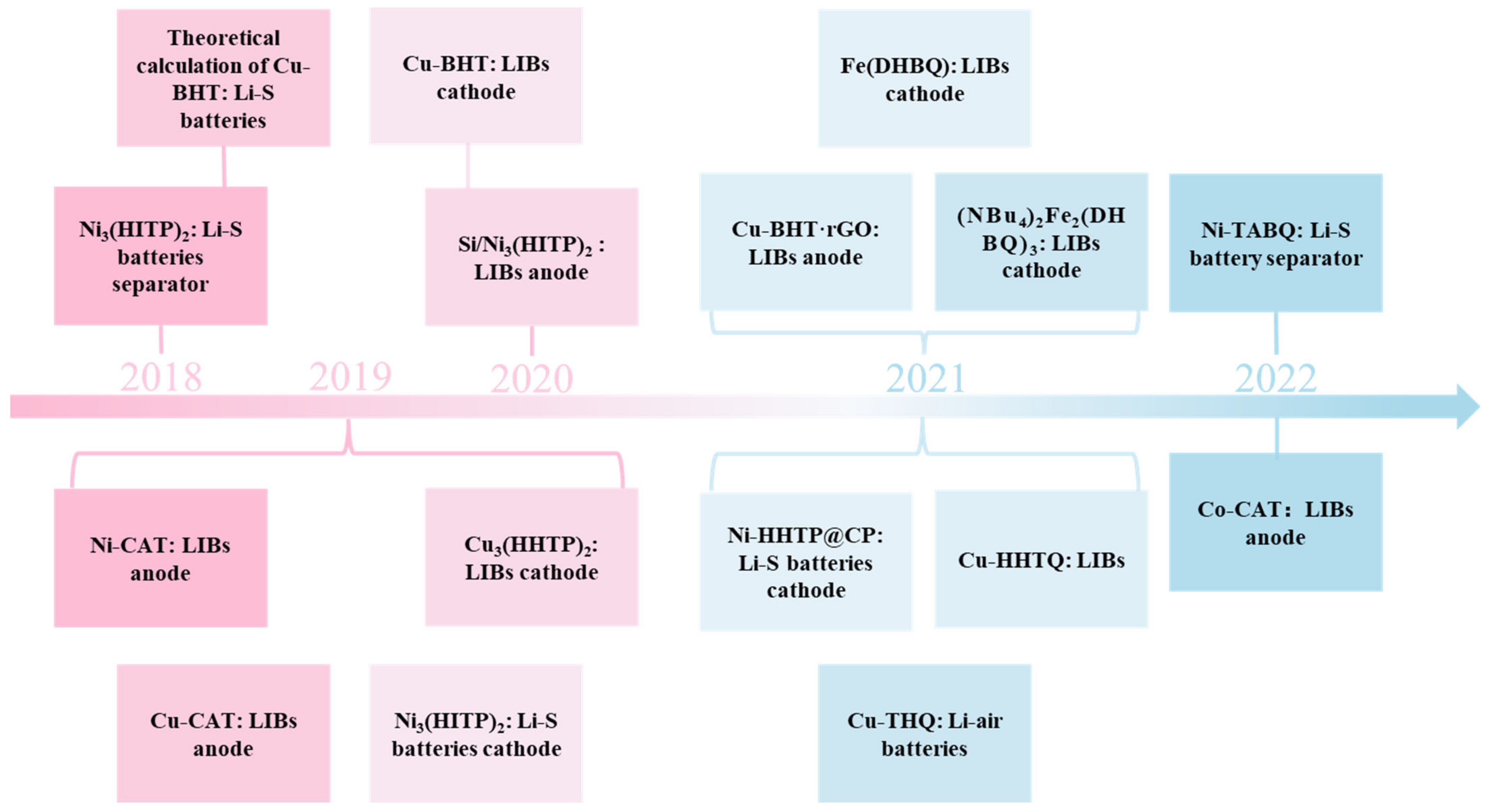
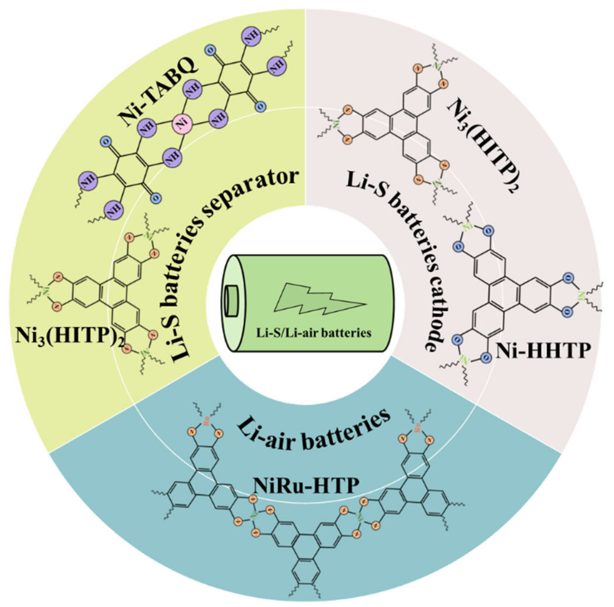
Metal–organic frameworks (MOFs) are coordination polymers that combine inorganic metal ions or metal clusters as junction points and organic ligands as connection bridges. MOFs are characterized by large specific surface areas, permanent pores, tunable pore diameters, and functions that can be modified according to needs [19,20]. As a result, MOFs have received considerable attention for their applications in gas storage, sensors, medicine, agronomy, and catalysis [21,22,23,24,25,26,27]. In recent years, MOF-based materials have been widely used for electrochemical energy storage systems. For example, Wang et al. optimized the lithium plating/stripping behavior through the carbonization of ZIF–67 [28]. Carbonized ZIF–67 as the anode for a lithium metal battery exhibited high coulombic efficiency (CE) and stable cycling performance at ultra-high current density according to experiments and theoretical calculations. Chen et al. prepared a novel MOF gel electrolyte that suppressed the formation of Li dendrites and also exhibited excellent performance at high temperatures [29]. However, most current MOFs exhibit poor electrical conductivity, which hinders their development in energy-storage systems [30,31,32]. Conductive metal–organic frameworks (c-MOFs) materials are a new type of material and have attracted much attention in recent years. c-MOFs are synthesized based on MOFs through the targeted design of their conductivity. Their excellent conductive ability makes them widely applicable in the field of energy storage, such as lithium batteries, fuel cells, supercapacitors, etc. The application of c-MOFs to improve the performance of rechargeable batteries opens a new path for energy storage research. Figure 1 unveils several common metal ions (Fe, Co, Ni, Cu, Zn, Pd, Ag, Pt, etc.) and organic ligands (BHT, THQ, TABTO, HHTP, etc.), which can form one-dimensional, two-dimensional, or three-dimensional MOFs. Meanwhile, some c-MOFs with metal elements belonging to different periods are visualized in Figure 1. The application of c-MOFs in sensors, supercapacitors, and water decomposition indicates that c-MOFs have pragmatic value [33,34,35,36,37]. The application of c-MOFs in rechargeable lithium batteries ameliorated the current challenges of lithium batteries through the promotion of charge transfer (Figure 2). From 2018 to date, there have been numerous examples of the application of c-MOFs in rechargeable lithium batteries, including the Ni3(HITP)2 diaphragm applied in Li–S batteries, Cu–BHT (butylated hydroxytoluene)/reduced graphene oxide (rGO) applied as an anodein LIBs, Cu–1,4–benzoquinone (THQ) improving the properties of Li–air batteries (Figure 3). A few excellent reviews on the development and applications of c-MOFs have been recorded [38,39,40,41]; however, the application of c-MOFs in rechargeable lithium batteries has not been specifically and systematically described. This review elucidates the conductive mechanism, the synthesis method, and experimental and theoretical research of c-MOFs in the new generation of rechargeable lithium batteries.

2. Conduction Mechanism

MOFs with high electrical conductivity have great potential for practical applications in energy storage and microelectronic devices [38]. In this section, the conduction mechanism of c-MOFs is introduced from the aspect of electrical conductivity. Generally, electrons enter the adjacent electronic orbits under an electromotive force to generate a conduction electron, while with ionization potentials, ions move away from electronic orbits in molecular gaps under ionization energy to generate conductive ions [42]. Electrical conductivity (σ) is a vital parameter for evaluating material conductivity. The calculation is expressed as follows:
σ = e μ e n e + μ h n h
where e is the electron, h represents the hole, μ indicates the carrier mobility, and n denotes the concentration of the carrier. As the mobility or carrier concentration increases, the conductivity of c-MOF increases, and the conductivity performance would be higher (Equation (1)). To build a new type of MOF with high conductivity, a high carrier concentration and good charge mobility are required. In MOFs, both organic ligands and metal ions provide charge carriers. Organic ligands exhibit two main functions such as promoting charge transfer and providing unpaired free radicals, whereas metals require holes or high-energy electrons [42]. Numerous factors affect the conductivity of MOFs in practical applications, such as temperature and crystallinity, which change the conductivity [43,44]. For highly ordered crystalline MOFs, the conduction behavior is elucidated in the energy band theory. The energy band is divided into a conduction band, valence band, and band gap. As the temperature reaches absolute zero, the electrons occupy the positions in the valence band, while the conduction band is empty. The energy levels of electrons in isolated atoms are discrete, and the outermost electrons fill the Fermi level. For the metal conductor, the conduction and valance bands overlap, and the band gap is equal to zero. The Fermi level in the overlapped part results in a high electron concentration, and the metal exhibits good conductivity. For semiconductors and insulators, the Fermi level lies in the band gap. The band gap of semiconductors is 0~3 eV, and the band gap of insulators is greater than 4 eV. At a certain temperature, electrons could absorb a certain amount of energy to transfer from the valence band to the conduction band. Meanwhile, a hole forms in the valence band and acts as a charge carrier. The carrier concentration is obtained from Equation (2):
n = n 0 exp E a K T
where n0 is a prefactor, Ea represents the activation energy, K represents Boltzmann’s constant, and T represents the absolute temperature [41]. Activation energy is the potential barrier energy required to overcome the thermal excitation of electrons. The activation energy determines the charge carrier concentration (Equation (2)). The charge transport mechanisms of c-MOFs include hopping transport and band transport [45]. Both mechanisms rely on a high spatial or energetic overlap and a low barrier between the organic ligand and the symmetric orbital of the metal ion. For hopping transport, carriers are localized in discrete energy levels and transition between in situ and adjacent sites under thermal activations. The transition probability can be obtained from Equation (3):
p = exp α R E K T
where E is the energy density between adjacent points, T denotes the absolute temperature, K represents Boltzmann’s constant, R indicates distance, and α is a constant. According to Equations (2) and (3), temperature has a great influence on carrier concentration and transition probability. The higher the temperature, the higher the carrier concentration and the transition probability. Therefore, conduction mechanisms would have great influences on the application of c-MOFs at different temperatures. It can be suggested that understanding the various conduction mechanisms would guide the application of c-MOFs in lithium batteries at different temperatures. In contrast, the band transport of charge carriers is delocalized. In the band transport mechanism, carrier mobility depends on the effective mass and the frequency of carrier scattering events. The equation is expressed as follows:
μ = e τ m
where m* is the effective mass of the carrier, τ represents the scattering time in the two collisions, and e denotes the carrier charge. The longer the scattering time or the smaller the carrier effective mass, the greater the mobility and conductivity of the MOFs (Equation (4)). Therefore, upon the design of the synthesis strategy of c-MOFs, the doping of impurities, or the existence of holes should be avoided to reduce the loss of scattering time. To obtain a small carrier effective mass, highly symmetric lattices, simple cells, and good dispersion of the energy band are required.
The hopping transport mechanism and the band transport mechanism are realized in the chemical construction of electronic c-MOFs through bonding, space, and guest molecules. The transport mechanisms for proton c-MOFs are realized via the Grotthuss mechanism [46,47]. Figure 4 depicts the three conductive mechanisms. The transport mechanism through a bond is dependent on a covalent bond formation. The energetic and steric overlap of organic ligands and metal ions facilitates charge transport [41,45]. In 2009, Takaishi reported Cu[Cu(pdt)2] as a typical example of the bond transport. The conductivity of Cu[Cu(pdt)2] was 6 × 10⁻⁴ S·cm−1 at 300 K, which was used as a high-power density porous electrode [48]. The charge transfer through space is mainly owing to the close packing and overlapping orbitals between adjacent ligands in rigid MOFs (such as π–π stacking between organic ligands), which is a non-covalent interaction. This solves the problem of fewer bonds between adjacent electroactive units and promotes charge transfer [49]. In 2018, Carol Hua et al. demonstrated an example of the transfer of electric charge through space. In Zn(II) frames containing cofacial thiazolo[5, 4-d]thiazole units, aromatic stacking interactions result in mixed valence states during electrochemical or chemical reduction [50]. The conduction via guest molecules introduces several guest molecules into the pore structure of MOFs to regulate the internal redox activity. Redox pairing and effective orbital overlap between the frame and guest molecules play a vital role in generating efficient charge transfer. A typical example was the immersion of MOFs Cu3(BTC)2 in methylene chloride saturated with tetracyanoquinodmethane by Yoon et al., which increased the conductivity of MOFs from 10−8 to 0.07 S·cm−1 [51]. The German chemist Theodor von Grotthuss contributed greatly to the development of the proton conduction mechanism. Hydrogen bonding is essential in this mechanism and is the key to elucidating proton transport. As a non-covalent interaction, the hydrogen bond is a weak bond formed between the hydrogen atom on the X–H (X is an atom more electronegative than hydrogen) of the molecular fragment and the same molecule or other molecules [52,53,54]. At room temperature, hydrogen bonds can form or break in response to thermal fluctuations, and that causes the transfer of protons in the Grotthuss mechanism.

3. Synthetic Methodologies

Most methods used in crystallography for growing single crystals can be used to prepare c-MOFs materials. The use of different methods or experimental parameters for the synthesis of c-MOFs materials can lead to variations in their properties such as crystallinity and microcrystal size, which can affect their electrical conductivity [55]. Therefore, a search for a suitable method to synthesize c-MOFs materials is vital [39].

3.1. Hydro-/Solvothermal Reactions

Owing to their simple operation and easy control, hydro-/solvothermal reactions are the major scheme for the synthesis of c-MOFs (Figure 5a). The reactants are dissolved in deionized water or other dissolvents, and the solution is heated or pressurized according to the reaction conditions so that the synthesis reaction could proceed normally [39]. The hydro-/solvothermal reactions are characterized by maneuverability and strong adjustability. The conditions of equal pressure and liquid phase reaction are conducive to the growth of perfect crystals with few defects. Through the adjustment of the parameters of the reaction solution, the particle size and morphology of the generated crystals also change [56,57,58]. In 2017, Li et al. synthesized Cu3(HHTP)2 (HHTP is 2,3,6,7,10,11–hexahydroxy–triphenylene) as the conductive additive and binder-free electrode for a solid-state supercapacitor [59]. However, the disadvantage of hydro-/solvothermal reactions is also significant. Upon the determination of reaction parameters and conditions, the crystal growth in the process of hydro-/solvothermal reactions could not be monitored. The synthesized polycrystalline films are rough and uneven [60].

3.2. Interface-Assisted Synthesis

Figure 5b shows several interfacial synthesis strategies, including liquid–liquid, solid–liquid, and gas–liquid interfaces. Numerous c-MOFs have been synthesized through interfacial synthesis strategies. Compared with a hydro/solvothermal synthesis, interfacial-assisted synthesis is an easier method for preparing two-dimensional (2D) c-MOFs films with high crystallinity and controllable thickness.
In 2015, Pal et al. added BHT in degassed dichloromethane, and then dissolved K3[Fe(CN)6] and K2PdCl4 in degassed deionized water (dichloromethane and water were mutually insoluble). Subsequently, the two solutions were mixed to form a two-phase system, and a prephenate dehydratase (PdDt) at the interface of the two-phases system after the two solutions contacted at the liquid–liquid interface through self-assembly synthesis [61]. In 2014, Sheberla et al. used the self-assembly synthesis method to mix metal source and organic ligands in an aqueous solution at the gas–liquid interface and then added ammonia to the mixture. Finally, a film was formed between the gas and liquid phases, and Ni3(HITP)2 was synthesized [62]. In 2019, Song et al. synthesized Cu3(HHTP)2 on the La0.67Sr0.33MnO3 electrode at the solid–liquid interface via self-assembly synthesis, which was highly crystalline [63].

3.3. Layer-by-Layer (LBL) Self-Assembly

LBL self-assembly as a multifunctional surface modification technology with low operation cost was first proposed by Iler in 1966 and has been developed since the 1990s [64]. Figure 5c illustrates the operation process of LBL self-assembly. First, the substrate is subjected to a functionalization process. Usually, a self-assembled monolayer (SAM) is generated on the surface to intercept metal ions. Then, with the weak interactions between molecules (such as coordination bond, hydrogen bond, and electrostatic attraction), layers spontaneously bond to form films with complete structure, stable performance, and certain specific functions [65,66]. Through the LBL self-assembly method, the gauge of the film can be regulated independently according to the actual needs [67,68]. Stavila et al. proposed a comprehensive mechanism of surface MOFs growth through the generation of Cu3(BTC)2 films on different substrates [66]. Shekhah et al. obtained Zn2(BTC)3 with high stability via the LBL self-assembly method, and the polymer did not decompose, regardless of the heating at 100 °C [69]. The LBL approach is relatively flexible in the steps of generating a deposition layer, which can immerse the substrate in a solution or spray the solution on the substrate. However, repeated experimental steps also lead to a longer consumption time for this approach [70].

4. Application of c-MOFs in LIBs

Currently, LIBs are used in most electronic devices in the market. During the discharge of LIBs, the lithium loses electrons and forms lithium ions, which dissolve in the electrolyte and transfer from the anode to lithium cobaltate. During the charging process of LIBs, lithium ions migrate from the cathode to the anode to gain electrons. The principle is shown in Figure 2, and the reaction equation is expressed as follows:
L i C o O 2 + C L i 1 x C o O 2 + L i x C  
Although LIBs are the most potential batteries, they also have several shortcomings. For example, uncontrollable lithium dendrite growth in the reaction process leads to short life cycle and reduced safety performance [71,72,73,74,75]. Researchers have continuously improved the performance of LIBs through various processes [76]. C-MOFs, as structurally tunable porous materials, can facilitate charge transfer and increase LIBs’ reaction rates, owing to their high electrical conductivity. Numerous active sites can be designed according to their tunable structures. The large pore structure of c-MOFs can provide abundant storage sites for lithium ions and inhibit lithium dendrite growth. Therefore, introducing c-MOFs to LIBs is a promising strategy (Figure 6). This section reviews the recent achievements of c-MOFs as anode and cathode materials for LIBs in sequential order.

4.1. LIBs Anode

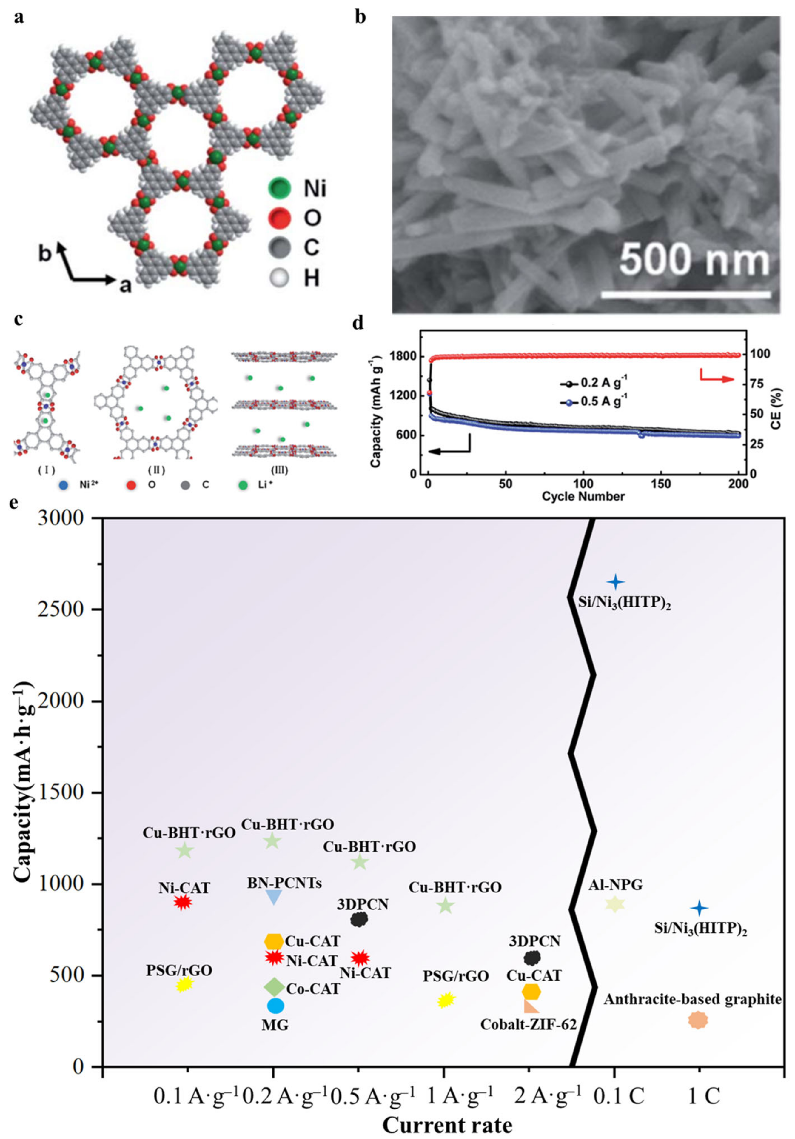
Designing advanced anode materials has been recognized as an effective approach for constructing suitable LIBs. To find electroactive materials with fast diffusion ability of Li-ions and gratifying capacity, Guo prepared a one-dimensional highly conductive porous Ni–catecholate (Ni–CAT) MOF via a hydrothermal method in 2019 and tested them as anode materials for LIBs (Figure 7a,b) [77]. The layer spacing of Ni–CAT was ~0.37 nm. According to the XRD diagram of the discharge process, the peak of the Ni–CAT electrode significantly changed. As the discharge process proceeded, the main peak slowly weakened until it disappeared. During the de-insertion process of Li+, the structure of Ni–CAT was gradually recovered. However, the insertion of Li+ disrupted the short-range order of Ni–CAT in the C–axis direction. Ni–CAT was characterized by three lithium storage sites, such as benzene rings, pores, and space between layers (Figure 7c). The reversible capacity of Ni–CAT at high current densities was greater than that of the other MOFs anodes owing to its high lithium diffusion capacity and excellent electron conduction performance, and the one-dimensional porous structure provided an effective channel for lithium-ion diffusion. The reversible capacities of Ni–CAT electrodes were 626 mA·h·g−1 and 592 mA·h·g−1 after 200 cycles at current densities of 0.2 and 0.5 A·g−1. Excluding the first cycle, the CE value of each cycle was ~100% (Figure 7d). Concurrently, the structure of Ni–CAT remained stable after 300 cycles. Ni–CAT electrode exhibited good crystallinity, with a long-range order on the a and b sides and short-range order on the C–axis. This study shows the excellent performance of Ni–CAT MOF as an anode for LIBs. In 2019, Guo et al. used a solvothermal bottom-up strategy to synthesize one-dimensional c-MOF (Cu–CAT) nanowires [78]. This showed good diffusion coefficient of lithium ions, high electronic conductivity, and excellent lithium storage performance. As Cu–CAT was used as an anode for LIBs, the reversible capacities of Cu–CAT were 631 and 381 mA·h·g−1 after 500 cycles at current densities of 0.2 and 2 A·g−1, and the CE value of each cycle was 81% at 0.5 A·g−1. The fading rate was low as 0.038% per cycle. The energy density reached up to 275 W·h·kg−1 as the full cell was assembled. In 2022, Mao et al. synthesized Co–CAT c-MOF via a liquid-phase method. Its conductivity and one-dimensional structure could promote the rapid transport of ions, resulting in an excellent lithium storage capacity in LIBs [79]. As the half-cell was assembled for an electrochemical test, its reversible capacity was 800 mA·h·g−1 after 200 cycles at a current density of 200 mA·g−1. This showed that the Co–CAT electrode exhibited good structural stability. Upon the assemble of the full battery with LiCoO2, the capacity was 404 mA·h·g−1 after 100 cycles at current density of 200 mA·g−1. Co–CAT electrodes exhibited excellent lithium storage capacity in LIBs and good potassium storage capacity in potassium-ion batteries (PIBs). Similarly, as Co–CAT was used as the anode for PIBs, its capacity was 230 mA·h·g−1 after 700 cycles at 1.0 A·g−1. Meanwhile, an eight-electron transfer occurred in PIBs with excellent potassium storage performance. Owing to the conductivity of Co–CAT, the modified PIBs exhibited excellent electrochemical performance. Therefore, c-MOFs are very promising materials for applications in PIBs.
The anodes in LIBs usually undergo volume expansion during the lithiation process. In 2020, Aqsa Nazir et al. prepared Si/Ni3(HITP)2 (HITP represents 2,3,6,7,10,11–Hexaiminotriphenylene) composites as anodes for LIBs [80]. Ni3(HITP)2 promoted the rapid movement of lithium ions in the electrode, improved the lithium storage capacity and the electrode conductivity, and inhibited the volume expansion of Si owing to its open pore structure, high conductivity, and uniformly dispersed Ni and N heteroatoms. At any rate, the capacity of a silicon nanoparticle anode was lower than that of the Si/Ni3(HITP)2 anode, indicating that the Si/Ni3(HITP)2 anode exhibited excellent high-rate capability. The Si/Ni3(HITP)2 anode featured a higher CE close to 100%, regardless of the high discharge rate at 20 C, which indicates the excellent lithiation/de-lithiation reversibility of this electrode. The reversible capacity of Si/Ni3(HITP)2-assembled batteries was 876 mA·h·g−1 after 1000 cycles at 1 C, and CE was ~100%, indicating that Si/Ni3(HITP)2 electrode exhibited good cycling performance. Aqsa Nazir et al. also compared the c-MOFs electrode with the previously reported electrode. Compared with other electrodes, the c-MOF electrode exhibited a high reversible capacity of 2657 mA·h·g−1 after 100 cycles at 0.1 C. In 2021, Meng et al. synthesized a composite of Cu–BHT 2D c-MOF and rGO to solve the densification problem of Cu–BHT [81]. Compared with pristine Cu–BHT MOF composite, Cu–BHT and rGO composite exhibited good electrical conductivity and more redox-active sites. The composites were electrochemically tested as anodes for LIBs. The reversible specific capacities of rGO and Cu–BHT as a composite electrode were 1190.4, 1230.8, 1131.4, and 898.7 mA·h·g−1 with a ratio of 1:1 at current densities of 100, 200, 500, and 1000 mA·g−1, respectively. The reversible capacities of rGO and Cu–BHT were higher than those of pristine Cu–BHT MOFs.
In addition, in 2021, Yan synthesized the tricycloquinazoline (TQ) and two-dimensional c-MOF Cu–HHTQ (HHTQ = 2,3,7,8,12,13–hexahydroxytricycloquinazoline) cooperating with CuO4 [82]. The c-MOF possessed excellent lithium storage ability and high rate capability. The redox activity of TQ was verified by theoretical calculation and experiments for the first time. Electrochemical tests were carried out with Cu–HHTQ as the active material and Li as the electrode. In the first cycle, the discharge capacity was 1716 mA·h·g−1, and the charging capacity was 989 mA·h·g−1. The charging capacity was already one of the highest values in the existing reports. When the current density was 600 mA·g−1, the specific capacity of Cu–HHTQ was 657.6 mA·h·g−1, and the charge–discharge capacity remained at 82% for 200 cycles. Its specific capacity was also one of the highest values, as illustrated in Table 1. It was found that the Cu–HHTQ had partial charge capacitor storage in the scanning rate range of 0.2–1 mV·S−1, and contributed 39% to 58% of the capacitance. This was mainly attributed to the high conductivity, large specific surface area and continuous pores, as well as multiple redox activities.
Figure 7e shows the comparison of c-MOFs anode (Ni–CAT, Cu–CAT, Co–CAT, Cu–BHT·rGO, Si/Ni3(HITP)2) with some conventional carbon-based materials as anodes, such as porous graphite/rGO (PSG/rGO), cobalt–ZIF–62, modified graphite (MG), anthracite-base graphite, layers of nanoporous graphene (NPG) on the surface of Al thin films (Al–NPG), porous carbon nanotubes webs with high level of boron and nitrogen co-doping (BN–PCNTs), three-dimensional interconnected porous carbon nanoflakes (3DPCNs) [94,95,96,97,98,99,100]. As can be seen from the figure, the Cu–BHT·rGO and Si/Ni3(HITP)2 have obvious advantages at current densities of 0.1, 0.2, 0.5 and 1 A·g−1 or at rates of 0.1 and 1 C.

4.2. LIBs Cathode

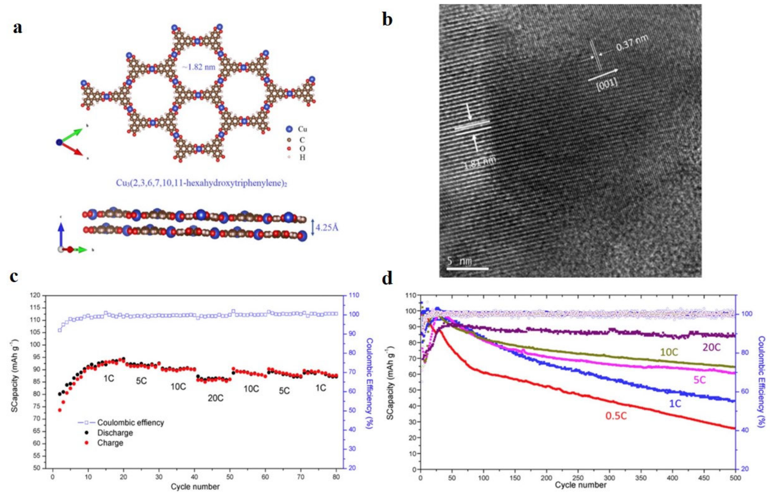
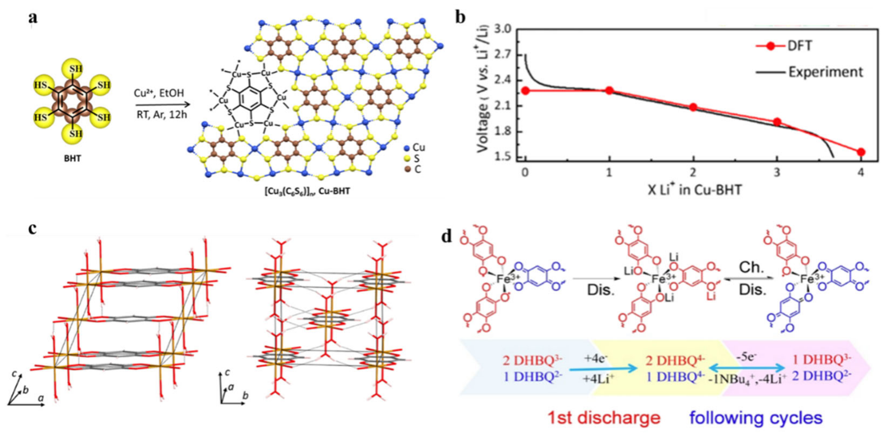
In addition to the construction of c-MOFs anodes, cathodes use c-MOFs to enhance battery performance. As cathode materials, the large aperture structure and high conductivity of c-MOFs could effectively improve the cathode capacity. In 2019, Gu et al. prepared a Cu3(HHTP)2 c-MOF cathode for LIBs (Figure 8a) [83]. The size of Cu3(HHTP)2 nanosheets was ~20–40 nm, showing an irregular shape. Figure 8b shows the high-resolution transmission electron microscope images. According to Brunauer–Emmett–Teller analysis, the specific surface area of Cu3(HHTP)2 reached 506.08 m2·g−1. The ideal specific surface area and effective pore structure of c-MOF were essential for lithium-ion embedding. During the charge/discharge cycling test with Cu3(HHTP)2 as the cathode, its discharge capacity increased with the number of cycles, indicating that the Cu3(HHTP)2 cathode was relatively stable. The capacity of the coin LIBs assembled with c-MOF as the cathode was 95 mA·h·g−1 after 60 cycles, and the CE value was 50% after 500 cycles. The capacity decay rate was 0.09% per cycle, and the CE value was 100%. During the discharge process, each unit of Cu2+ was reduced to Cu+ through the insertion of a Li+ unit. Correspondingly, a unit of Li+ was released during the charging process, and each unit of Cu+ was oxidized to Cu2+. Figure 8c,d show the capacity change of coin LIBs assembled with Cu3(HHTP)2 as the cathode g at a high current rate. The capacity of coin LIBs gradually decreased with enhanced current rates. As a low current rate was restored, the battery capacity was recovered, exhibiting good reversibility. The capacity retention rate of coin LIBs increased with the increasing current rate. After 500 cycles at 20 C, more than 85% of the battery capacity was maintained with a decay rate of 0.023% per cycle. In 2020, Wu et al. synthesized a Cu–BHT 2D c-MOF through the self-assembly reaction of a BHT monomer and Cu(II) salt in ethanol (Figure 9a), exhibiting room temperature conductivity of 231 S·cm−1 [84]. The thermogravimetric analysis and acid-base tests revealed that the c-MOF exhibited high thermal and chemical stability. Figure 9b shows the experimental and theoretical calculation results. The c-MOF was used as a cathode material for LIBs with the potential range of 1.5–3.0 V (versus Li+/Li), and a four-lithium-ion storage reaction at redox-active sulfur atoms occurred on each Cu–BHT unit. The electrochemical test revealed that the reversible capacity of Cu–BHT as the cathode was 232 mA·h·g−1, which was close to its theoretical capacity of 236 mA·h·g−1, and each unit of Cu–BHT stored ~ 3.94 lithium ions. The lifespan and rate capacity of the Cu–BHT cathode were tested. The results show that after 500 cycles at a current density of 300 mA·g−1, the capacity decay rate was 0.048% per cycle. After 10 days of shelving, the capacity decay rate was 98.1% per cycle. Owing to its inherent high conductivity and the strong coordination of Cu(II) and BHT in the complete π-d conjugated system, the Cu–BHT cathode exhibited good cycling performance and longer service life.
The performance of LIBs was improved with increasing conductivity of the active cathode. In 2021, Kazuki Kon et al. reported a one-dimensional c-MOF Fe(DHBQ)–(H2O)2 (DHBQ is 2,5–dihydroxy–1,4–benzoquinone) [101]. Figure 9c shows the electron transfer interaction between ligands and metal ions of c-MOF. Fe(DHBQ)–(H2O)2 has no pore structure owing to the removal of water, while Fe(DHBQ) has a permanent porous structure in an anhydrous phase. The conductivity of c-MOF increased to 1.0 × 10⁴ S·cm−1 during the desolvation process, and the conductivity at room temperature was 5 × 10⁻⁶ S·cm−1. As Fe(DHBQ), acetylene black, and polytetrafluoroethylene were mixed in a certain proportion to design a cathode for LIBs, the initial discharge capacity of LIBs reached 264 mA·h·g−1.
Similarly, in 2021, Dong et al. synthesized a conductive three-dimensional MOF (NBu4)2Fe2(DHBQ)3 via a simple reaction using mixed of valence 2,5−dihydroxyben−zoquinone (DHBQ2-/3-) as the linker and Fe3+ as the metal center with a conductivity of 1.07 mS·cm−1 [85]. The battery based on the c-MOF cathode exhibited a capacity of 91.4% and a high CE of ~100% after 350 cycles at a current density of 500 mA·g−1. With the current density up to 1000 mA·g−1, the reversible capacity reached 94.4 mA·g−1, and the capacity retention rate was 71.5% after 1000 cycles. The outstanding electrochemical properties of c-MOF cathode were attributable to the high conductivity and hollow structure of (NBu4)2Fe2(DHBQ)3, which can promote the migration kinetics of electrons and ions. Figure 9d shows the reaction mechanism of the charging and discharging process. During the discharge process, both DHBQ2− and DHBQ3− underwent a four-electron reaction. In the charging process, DHBQ4- underwent a five-electron reaction with NBu4+ and four lithium ions. Summarily, the inherent pore structure of c-MOFs enhances the specific surface area of electrodes in LIBs, and increases the number of active sites. This has a positive effect on restraining the volume expansion of the battery during the charging and discharging process. The inherent high conductivity of c-MOFs will promote the speed of ion and electron transfer which is essential for enhancing the performance of LIBs.

5. Application of c-MOFs in Li–S Batteries and Li–Air Batteries

Unlike LIBs that require lithium compounds and graphite as electrodes, Li–S batteries generally use sulfur as the cathode and lithium foil as the anode, and Li–air batteries can directly use lithium and oxygen in the air as electrodes. Li–S and Li–air batteries are ascribed to an electrochemical mechanism different from the ion extraction–insertion mechanism of LIBs. Additionally, Li–S and non-liquid Li–air batteries exhibit high theoretical energy densities of 2600 and 11,200 W·h·kg−1, respectively, [102,103,104,105] compared with LIBs (250–300 W·h·kg−1) [106,107]. The following section focuses on the achievements of using c-MOFs to enhance Li–S batteries and Li–air batteries (Figure 10).

5.1. Li–S Batteries

A Li–S battery consists of a sulfur composite cathode, a lithium metal anode, and an electrolyte between them (Figure 2). Since elemental sulfur is a poor conductor of electrons, sulfur composite positive electrodes consist of the elemental sulfur, a conductive agent, and a polymer binder. Currently, widely used Li–S batteries are organic electrolytes based on organic solvents and lithium salts. According to Equation (6), the metal lithium anode loses electrons in the discharge process to generate lithium ions, and the metal lithium is continuously dissolved in the electrolyte. During the charging process, lithium ions gain electrons from the electrolyte, and metallic lithium is recovered, which continuously forms sediments on the pole.
2 L i + + S + 2 e L i 2 S  
Owing to the high theoretical specific energy and capacity (1675 mA·h·g−1) of sulfur as a cathode for lithium batteries, Li–S batteries have received great attention as a next-generation energy storage system [108,109,110]. Moreover, sulfur is cheap (<USD 150 per metric ton), environmentally friendly, and abundant (17th richest element) [111,112,113]. However, the poor cyclability and slow charging/discharging rate of Li–S batteries are the bottlenecks restricting their development [114,115,116]. To address the problems associated with Li–S batteries such as the insulation performance of sulfur [117], the large volume change during the battery discharge process [118], and the reciprocating migration (shuttle effect) of polysulfides (Li2Sn, 4 ≤ n ≤ 8) formed between positive and negative electrodes [119], the application of MOFs in Li–S batteries has received great attention owing to the high specific surface area, adjustable structures, ideal crystallization, and rich catalytic sites [86,120,121,122,123,124]. However, the inherent electronic conductivity of conventional MOFs materials is usually poor, resulting in unsatisfactory reaction efficiency and low utilization of active species [40]. In contrast, c-MOFs have shown great potential for wide applications in Li–S batteries owing to their excellent electronic conductivity.
In 2018, Li et al. performed first-principles calculations via the projected-augmented wave method according to density functional theory (DFT) [125]. The adsorption of S8/lithium polysulfides (LiPSs Li2Sn, n = 1, 2, 4, 6, and 8) on Cu–BHT monolayers was systematically studied. The results revealed that the outstanding conductivity of the Cu–BHT monolayer was the key factor for improving sulfur availability. Owing to the combination of Li–S bonds and Sa–Cu bonds, the Cu–BHT monolayer interacted with LiPSs and guided the uniform diffusion of Li2S. The above conclusions indicated that the Cu–BHT monolayer played a vital role in inhibiting the shuttling of soluble LiPSs and improving the charging–discharging rate and cyclability.

5.1.1. Li–S Batteries Separators

Experimentally, the surface in situ modification of traditional separators using c-MOFs materials is a promising strategy for separator modification and interfacial stabilization of lithium metal batteries. In 2018, Zang et al. developed a liquid–solid interface via a self-assembly method to design and prepare Ni3(HITP)2 materials [87]. The material was a large area of the microporous membrane without cracks. Concurrently, the concept of a polysulfide barrier in Li–S batteries was put forward by Zang et al. Crystalline microporous membrane was a beneficial barrier layer that could improve the performance of Li–S batteries. The microporous film exhibited a low density, a large area (more than 75 cm2), adjustable thickness (90–970 nm), and high conductivity (3720 S·m−1). Additionally, the microporous film exhibited a highly neat pore structure and excellent ability to adsorb polysulfides, which was an ideal barrier. The results showed that the capacity, rate function, and cyclability of the Li–S batteries were significantly improved after the film was used to optimize the Li–S batteries, and the average capacity decay rate was 0.032% per cycle.
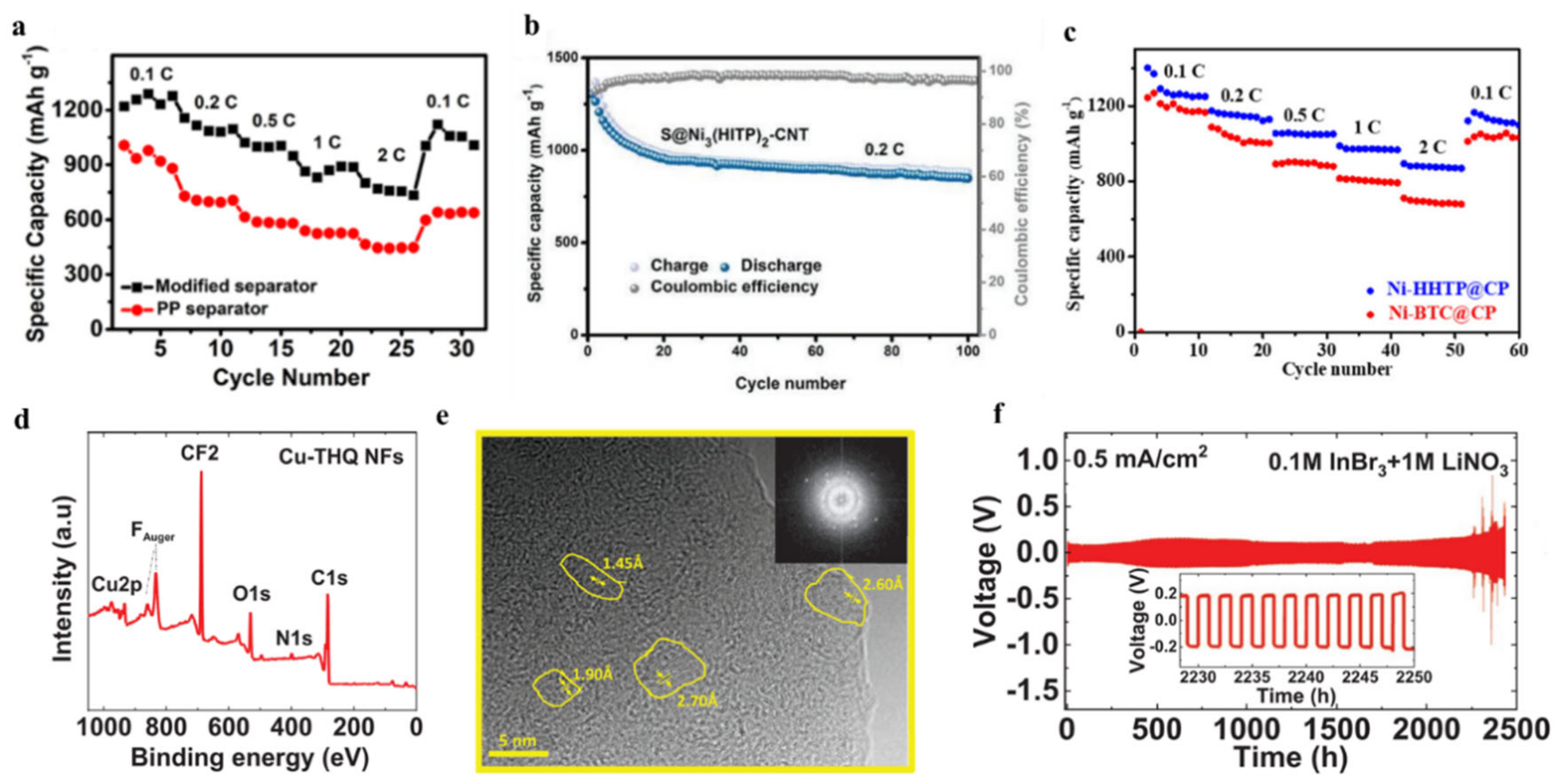
In 2019, Chen et al. prepared a membrane modified using Ni3(HITP)2 layers through a simple filtration method [88]. The battery separators achieved a specific capacity of 1220.1 mA·h·g−1 at a discharge rate of 0.1 C, a specific capacity of 800.2 mA·h·g−1 at 2 C, and a specific capacity of 1008.0 mA·h·g−1 at 0.1 C (Figure 11a). The designed diaphragm exhibited good conductivity, a well-distributed pore structure, and good hydrophilicity, which adsorbed the polysulfide to reduce blockage and improved the cycling stability of the battery. Therefore, the separator can slow down the shuttle effect of Li–S batteries and enhance their capacity rate.
In 2022, Xiao et al. proposed a strategy to simultaneously integrate two catalytic centers with different properties (Ni–N4 active site and quinone chemical group) into one c-MOF Ni–tetraaminobenzoquinone (Ni–TABQ) [89]. This strategy could effectively elucidate the concept of efficient multi-step catalytic conversion of LiPSs using MOFs. Additionally, a Ni–TABQ film prepared in situ on the polypropylene separator had a density of 0.075 mg·cm−2 and a thickness of 1.8 μm. Systematic electrochemical experiments and detailed DFT simulation calculations show that the c-MOF film can simultaneously realize the sieving, adsorption, and multi-step catalytic conversion of polysulfide ions, which significantly improves the capacity and lifespan of Li–S batteries.

5.1.2. Li–S Batteries Cathode

Regarding the use of c-MOFs to modify the membrane, its modification on the cathode has also received attention. In 2019, Cai et al. synthesized the c-MOF Ni3(HITP)2 via a straightforward hydrothermal approach and studied its electrochemical behavior as a cathode for Li–S batteries [90]. Ni3(HITP)2 is hydrophilic and can adsorb polysulfides, and its shape is similar to the two-dimensional layered structure of graphene. Ni3(HITP)2 was an effective physical barrier that could inhibit the shuttle effect and improve cycling stability. The sulfur body in Li–S batteries required the use of c-MOFs to enhance its performance. The experimental results showed that the carbon nanotube-based S@Ni3(HITP)2 cathode displayed excellent sulfur availability, rate performance, and stable cycling endurance. After 100 cycles at 0.2 C, a high primary capacity of 1302.9 mA·h·g−1 and a good capacity maintenance of 848.9 mA·h·g−1 occurred (Figure 11b).
In 2021, Wang et al. adjusted the surface chemistry of self-supporting carbon paper (CP) using Ni–HHTP materials to facilitate polysulfide conversion in Li–S batteries [91]. The electronic conductivity of Ni–HHTP was higher than that of traditional MOFs (6 × 10⁻³ S·cm−1). Ni–HHTP exhibited strong chemisorption of polysulfides, which suppressed the shuttle effect, thus improving the utilization rate of active materials in Li–S batteries. The Li–S batteries loaded with Ni–HHTP@CP materials under the conditions of high sulfur load and reduced electrolyte exhibited excellent rate performance, a specific capacity of 892 mA·h·g−1 at a discharge rate of 2 C (Figure 11c). The Ni–HHTP@CP material proves that the synergistic effect of strong polysulfide adsorption and excellent electronic conductivity is essential for the design of cathode materials for Li–S batteries.
The aforementioned studies have shown that whether c-MOFs were used for the diaphragm or positive electrode of Li–S batteries, as the c-MOFs adsorbed polysulfides, the shuttle effect was restrained, thus improving the battery performance. This discovery provides a clear direction for the design of Li–S battery modification.

5.2. Li–Air Batteries

As a new generation of large-capacity batteries, Li–air batteries have attracted special interest. The Li–air battery consists of a pure lithium metal sheet, an electrolyte, and an air cathode containing catalysts (Figure 2). The Li–air battery is a simple layered structure. The diaphragm is immersed in the electrolyte and arranged between the cathode and the anode. The positive side of the Li–air battery is covered with oxygen pores. In addition, the positive electrode uses a gas diffusion layer electrode with composite porous carbon as a collector. In the discharge reaction, the metal lithium of the cathode dissolves and reacts with oxygen on the positive electrode, and lithium peroxide is precipitated (Li2O2). Charging is the reverse of the discharge reaction. The Li2O2 of the positive electrode is decomposed to release oxygen, and the metal Li is precipitated on the negative electrode. The overall equation is written as follows:
2 L i + + O 2 + 2 e L i 2 O 2
In theory, since oxygen is not limited as a positive reactant, the battery capacity only depends on the lithium electrode. The theoretical energy density of Li–air batteries is higher than that of LIBs and it is very promising for automotive batteries [126,127]. However, owing to their fatal defects, Li–air batteries have not been popularized. During discharge and charging reactions, solid reaction products (such as Li2O2) accumulate on the cathode surface, and the contact between oxygen and electrolyte is blocked; thus, the discharge would be stopped [92,128,129]. Additionally, the decomposition efficiency of Li2O2 generated during battery operation is low, and Li2O2 would diffuse and accumulate on the cathode surface, which affect the cycling performance of the battery [130]. To optimize battery performance, MOFs have been used as ideal candidates for studying electrode materials in electrochemical energy applications, particularly in secondary batteries such as Li–air batteries, owing to their excellent properties. However, because of their insulation, traditional MOFs are distant from the standard of practical positive electrode materials. Therefore, the synthesis of c-MOFs with high conductivity and structural stability via various design strategies is crucial for their application in Li–air batteries [131,132].
In 2022, Majidi et al. peeled bulk Cu–THQ into 2D nanosheets (NFs) via stripping technology, and then coated the peeled Cu–THQ–NFs on a gas diffusion electrode (GDE) [93]. Figure 11d shows the XPS survey spectrum of Cu–THQ–NFs coated on a GDE. DFT calculation of Li2O2 growth on Cu–THQ framework showed that Cu was the growth site, and its formation was thermodynamically favorable. Because the surface of c-MOFs was highly active, it could promote the formation of nanocrystalline Li2O2 in the amorphous Li2O2 region (Figure 11e). These characteristics, combined with the InBr3 electrolyte additive, enabled the battery to operate at a high charge/discharge current density (Figure 11f).
Overall, c-MOF is a promising material, regardless of the numerous challenges. The progress of c-MOF synthesis will lead to rapid and sustainable development in the fields of electronics and electrochemistry. Moreover, c-MOF has made inspiring progress in numerous aspects when applied to potential rechargeable lithium batteries, although we are a significant distance from commercialization. As the remaining problems in these batteries have been solved by several researchers in the exponentially growing battery market, other batteries are likely to coexist with LIBs and may dominate the rechargeable lithium battery market position over the next decade.

6. Theoretical Calculation

First-principles calculations that rely on DFT are crucial in scientific research. For example, DFT calculations can effectively predict the application of new materials, which is instructive for subsequent experiments and validate the experimental results. In the field of energy storage, DFT calculations can determine the stability of a material structure, calculate the free energy, and then elucidate the electrochemical reactions that occurred in the reaction process. DFT calculations can also calculate the distribution of electrons in new materials. For example, band structure and density of state (DOS) can determine whether a novel electrode material is a metal, a semiconductor or an insulator. Concurrently, DFT calculations can not only simulate the ion diffusion kinetics to elucidate the electrochemical reaction rate but also simulate the ion adsorption kinetics [133,134]. DFT calculations help to guide the experiment and save cost and time. Currently, the application of c-MOFs in the modification of rechargeable lithium batteries has not been sufficiently developed. Therefore, providing theoretical predictions and guidance for the research and development of advanced materials in this field is vital. This section reviews several works conducted via the DFT method, such as the differences between Cu3(HHTP)2 before and after lithiation, the structural changes of TQ during lithiation, the stable adsorption sites of lithium in Cu–BHT, and the advantages of Ga3C6N6 as the anode for LIBs.
Gu et al. performed DFT calculations to elucidate the structural differences between the original and lithiated Cu3(HHTP)2 in LIBs (Figure 12a) [83]. As lithium ions were intercalated into Cu3(HHTP)2, each lithium ion was adsorbed on the copper atoms between the layers, which led to the structure relaxation, and a slight decrease in the α and β angles. Other lattice parameters were almost unchanged, indicating the stability of the hexagonal frame. However, the Cu2+ of Cu3(HHTP)2 was reduced to Cu+ to adsorb a Li+, resulting in the reduction in the repulsion between the layers in the framework and a decrease in the crystal volume. Gu et al. also calculated the average redox potential of Cu3(HHTP)2, which was consistent with the experimental results. Similarly, Wu et al. calculated the stable adsorption sites of lithium in Cu–BHT via the DFT method [84]. The benzene ring locates at the center of the structure, and the five-membered ring composed of S, C, Cu and the six-membered ring structure composed of S, Cu are calculated and analyzed (Figure 12b). The results revealed that the C site of the benzene ring was suitable for lithium storage, and the conductivity of lithium atoms increased after the insertion of Cu–BHT. The original Cu–BHT exhibited metallic properties and a small band gap, resulting in high conductivity (Figure 12c). The emergence of new electronic states in the six-membered rings and carbon ring proves that the conductivity is higher compared with that of the original Cu–BHT. To elucidate the lithium storage mechanism of TQ in LIBs, Yan et al. used DFT to calculate the structural change of TQ during the lithiation process [82]. Computational results showed that TQ underwent a nine-electron reaction during the lithiation and delithiation. Figure 12d shows the structural change from TQ to TQ-9Li. 1 Li+–3 Li+ combined with three pyrimidine N atoms to form TQ-Li, TQ-2Li, and TQ-3Li. The 4 Li+–6 Li+ were distributed around the central N atom, and the C=C bond was adjacent to the C=N bond owing to electrostatic interactions. As 6 Li+ were inserted, the electrostatic potential of the terminal benzene ring became negative, and the 7 Li+–9 Li+ combined with the terminal benzene ring, respectively. Additionally, DFT calculation used in the design of c-MOFs also occupied a vital position in the c-MOFs structure. Wu et al. theoretically designed a 2D MOF of Ga3C6N6 based on Cu–BHT via the isoelectronic substitution strategy [135]. The structure of the Ga3C6N6 MOF monolayer remained stable at 2400 K, indicating that the MOF exhibited excellent thermal stability. The theoretical calculation results show that Ga3C6N6 had a moderate open circuit potential (0.96 V), a low diffusion barrier (1.12 eV), and a high theoretical specific capacity (330 mA·h·g−1). According to the calculated band structure and DOS of Ga3C6N6 adsorbed by lithium atoms in Figure 12e,f, a single lithium atom was adsorbed, and the lithium atom did not contribute to DOS around the Fermi level, but with increasing adsorption quantity of lithium atoms, the contribution of lithium atoms gradually increased. Therefore, Ga3C6N6 exhibited excellent lithium storage capacity and good electronic conductivity. The above calculation results show that Ga3C6N6 is a promising anode material for LIBs.
Although the experimental results are important for a new study, DFT calculations can expose some unobservable details, such as the lithium storage sites for c-MOFs, the changes in the structure of c-MOFs during the lithiation and delithiation processes, and the reaction mechanism. These theoretical findings are vital for improving the performance of rechargeable lithium batteries.

7. Conclusions and Outlook

As one of the better-developed batteries currently, the development of rechargeable lithium batteries is hindered by problems, such as dendrite generation during operation, volume expansion, polysulfide formation, and loss of active materials. To effectively solve the above-mentioned problems, the specific surface area of the electrode, the conductivity of the electrode surface, and the lithium storage capacity of the electrode have been increased. In recent years, MOFs have emerged as a promising material for several industrial applications owing to their permanent pore structures, large specific surface areas, adjustable structures and simple synthesis methods. However, the insulating nature of most MOFs limits their application in the energy field. C-MOFs have received great attention owing to their high conductivity compared with conventional MOFs. The applications of c-MOFs are outlined as follows. (1) For LIBs, the inherent large specific surface area, porous structure, and high electrical conductivity of c-MOFs provide LIBs with more active sites and lithium storage sites, which promote the migration rate of ions. (2) According to Li–S batteries, c-MOFs can adsorb polysulfide generated during the reaction, either as a cathode or as a diaphragm, which play a vital role in inhibiting the shuttle effect. (3) For Li–air batteries, c-MOFs have been used in these novel energy systems, and they could operate stably at high current densities. (4) DFT calculations play a vital role in predicting and guiding the synthesis of composite electrodes. Presently, c-MOFs are gradually used in rechargeable lithium batteries and energy and electronic devices. This review elucidates the conductive mechanism of c-MOFs, then introduces the preparation methods of c-MOFs, and summarizes the applications of c-MOFs in rechargeable LIBs, Li–S batteries, and Li–air batteries according to the classification of batteries. The performance of c-MOFs in rechargeable lithium batteries is summarized in Table 1.
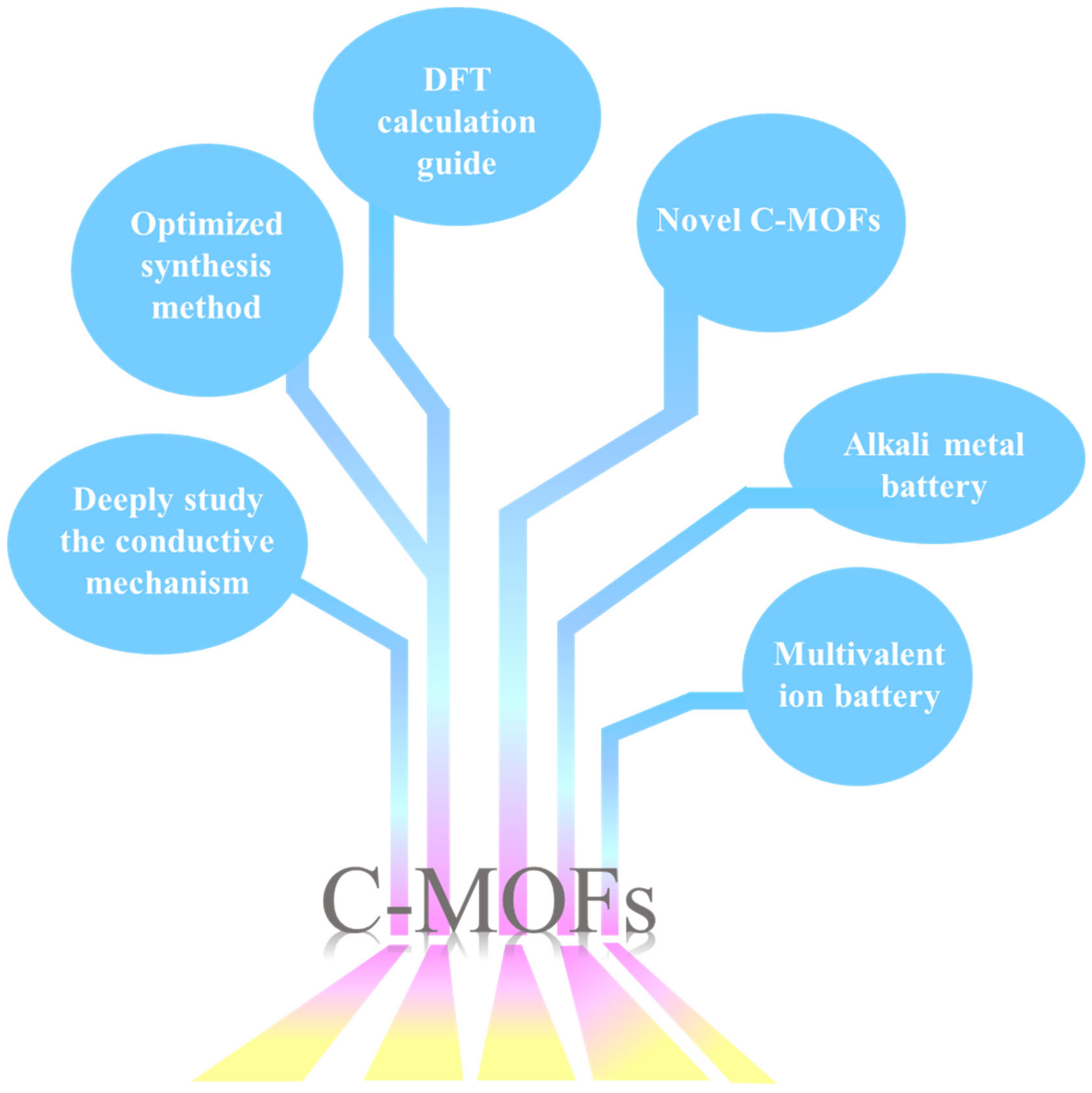
C-MOFs combine the advantages of metal ions and organic ligands to solve the problem of low conductivity of materials owing to the difficulty in functionalization of metal ions and the inability of organic ligands to achieve a long-range order. However, c-MOFs require several developments. (1) The elucidation of the conduction and energy storage mechanism of electrode materials helps to control the synthesis of c-MOFs electrodes and enhance the battery performance. Different c-MOFs have distinct conduction and energy storage mechanisms. Therefore, exploring the mechanism of c-MOFs is vital. DFT calculations are of great significance in this aspect. (2) Presently, several preparation methods of c-MOFs are relatively complex owing to the harsh conditions and long-synthesis time, which is not conducive for large-scale production. The optimization of the preparation method of c-MOFs through a decrease in the synthesis time and adjusting the synthesis conditions to achieve low-cost, large-scale production still requires continuous improvement. (3) DFT calculations are significant for developing various new organic ligands and guiding the synthesis of new c-MOFs. c-MOFs combined several functional materials with a specific ability to provide a stronger binding force. The heat resistance and acid and alkaline resistance of c-MOFs can be effectively improved. Continuous innovation is required for the improvement of c-MOFs. (4) C-MOFs can be used in the fields of lithium batteries, other alkali metal batteries (sodium-ion batteries and KIBs), and multivalent metal-ion batteries (zinc-ion batteries and magnesium-ion batteries). Although c-MOFs have several applications presently, they still have huge development potential in this field. We believe that the research and application of c-MOFs in the field of electrochemical energy storage and conversion will be more extensive as shown in Figure 13. In this field, opportunities and challenges coexist.

Author Contributions

F.D. and Y.Z.: Writing—original draft preparation; Y.Y.: Writing—reviewing and editing, supervision, funding acquisition. All authors have read and agreed to the published version of the manuscript.

Funding

This work was financially supported by National Natural Science Foundation of China (No. 61904073), Spring City Plan-Special Program for Young Talents (ZX20210014), Yunnan Talents Support Plan for Yong Talents, Yunnan Local Colleges Applied Basic Research Projects (202101BA070001-138), Scientific Research Fund of Yunnan Education Department (2022Y717), Scientific Research Fund of Yunnan Education Department (2023Y0883).

Institutional Review Board Statement

Not applicable.

Informed Consent Statement

Not applicable.

Data Availability Statement

Not applicable.

Conflicts of Interest

The authors declare no conflict of interest.

References

  1. Xu, X.; Liu, J.; Liu, J.; Ouyang, L.; Hu, R.; Wang, H.; Yang, L.; Zhu, M. A General Metal-Organic Framework (MOF)-Derived Selenidation Strategy for In Situ Carbon-Encapsulated Metal Selenides as High-Rate Anodes for Na-Ion Batteries. Adv. Funct. Mater. 2018, 28, 1870108. [Google Scholar] [CrossRef]
  2. Shen, K.; Xu, X.; Tang, Y. Recent progress of magnetic field application in lithium-based batteries. Nano Energy 2022, 92, 106703. [Google Scholar] [CrossRef]
  3. Yu, L.; Liu, J.; Xu, X.; Zhang, L.; Hu, R.; Liu, J.; Yang, L.; Zhu, M. Metal–Organic Framework-Derived NiSb Alloy Embedded in Carbon Hollow Spheres as Superior Lithium-Ion Battery Anodes. ACS Appl. Mater. Interfaces 2017, 9, 2516–2525. [Google Scholar] [CrossRef] [PubMed]
  4. Yu, Y.; Wang, D.; Luo, J.; Xiang, Y. First-principles study of ZIF-8 as anode for Na and K ion batteries. Colloids Surf. A Physicochem. Eng. Asp. 2023, 659, 130802. [Google Scholar] [CrossRef]
  5. Nasser, O.A.; Petranikova, M. Review of Achieved Purities after Li-Ion Batteries Hydrometallurgical Treatment and Impurities Effects on the Cathode Performance. Batteries 2021, 7, 60. [Google Scholar] [CrossRef]
  6. Suzanowicz, A.M.; Mei, C.W.; Mandal, B.K. Approaches to Combat the Polysulfide Shuttle Phenomenon in Li–S Battery Technology. Batteries 2022, 8, 45. [Google Scholar] [CrossRef]
  7. Yu, Y.; Hu, S. The applications of semiconductor materials in air batteries. Chin. Chem. Lett. 2021, 32, 3277–3287. [Google Scholar] [CrossRef]
  8. Yu, Y.; Hu, S.; Huang, J. Germanium-modified silicon as anodes in Si-Ge air batteries with enhanced properties. J. Phys. Chem. Solids 2021, 157, e110226. [Google Scholar] [CrossRef]
  9. Wang, K.; Pei, S.; He, Z.; Huang, L.-A.; Zhu, S.; Guo, J.; Shao, H.; Wang, J. Synthesis of a novel porous silicon microsphere@carbon core-shell composite via in situ MOF coating for lithium ion battery anodes. Chem. Eng. J. 2019, 356, 272–281. [Google Scholar] [CrossRef]
  10. Liu, W.; Cheng, P.; Yan, X.; Gou, H.; Zhang, S.; Shi, S. Facile One-Step Solution-Phase Route to Synthesize Hollow Nanoporous CuxO Microcages on 3D Copper Foam for Superior Li Storage. ACS Sustain. Chem. Eng. 2021, 9, 4363–4370. [Google Scholar] [CrossRef]
  11. Yu, Y.; Hu, S.; Huang, J. Adsorption and diffusion of lithium and sodium on the silicon nanowire with substrate for energy storage application: A first principles study. Mater. Chem. Phys. 2020, 253, 123243. [Google Scholar] [CrossRef]
  12. Collins, G.A.; Geaney, H.; Ryan, K.M. Alternative anodes for low temperature lithium-ion batteries. J. Mater. Chem. A 2021, 9, 14172–14213. [Google Scholar] [CrossRef]
  13. Hou, J.; Ma, X.; Fu, J.; Vanaphuti, P.; Yao, Z.; Liu, Y.; Yang, Z.; Wang, Y. A green closed-loop process for selective recycling of lithium from spent lithium-ion batteries. Green Chem. 2022, 24, 7049–7060. [Google Scholar] [CrossRef]
  14. Dai, X.; Zhang, X.; Wen, J.; Wang, C.; Ma, X.; Yang, Y.; Huang, G.; Ye, H.-M.; Xu, S. Research progress on high-temperature resistant polymer separators for lithium-ion batteries. Energy Storage Mater. 2022, 51, 638–659. [Google Scholar] [CrossRef]
  15. Yan, C.; Zhang, X.-Q.; Huang, J.-Q.; Liu, Q.; Zhang, Q. Lithium-Anode Protection in Lithium-Sulfur Batteries. Trends Chem. 2019, 1, 693–704. [Google Scholar] [CrossRef]
  16. Zhou, L.; Danilov, D.L.; Qiao, F.; Wang, J.; Li, H.; Eichel, R.-A.; Notten, P.H.L. Sulfur Reduction Reaction in Lithium-Sulfur Batteries: Mechanisms, Catalysts, and Characterization. Adv. Energy Mater. 2022, 2202094. [Google Scholar] [CrossRef]
  17. Ko, S.; Yoo, Y.; Choi, J.; Lim, H.-D.; Park, C.B.; Lee, M. Discovery of organic catalysts boosting lithium carbonate decomposition toward ambient air operational lithium-air batteries. J. Mater. Chem. A 2022, 10, 20464–20472. [Google Scholar] [CrossRef]
  18. Wu, Z.; Tian, Y.; Chen, H.; Wang, L.; Qian, S.; Wu, T.; Zhang, S.; Lu, J. Evolving aprotic Li–air batteries. Chem. Soc. Rev. 2022, 51, 8045–8101. [Google Scholar] [CrossRef]
  19. Wada, K.; Sakaushi, K.; Sasaki, S.; Nishihara, H. Multielectron-Transfer-based Rechargeable Energy Storage of Two-Dimensional Coordination Frameworks with Non-Innocent Ligands. Angew. Chem. Int. Ed. 2018, 57, 8886–8890. [Google Scholar] [CrossRef]
  20. Liang, Z.; Qu, c.; Guo, w.; Zou, R.; Xu, Q. Pristine Metal-Organic Frameworks and their Composites for Energy Storage and Conversion. Adv. Mater. 2018, 30, 1702891. [Google Scholar] [CrossRef]
  21. Huang, W.; Huang, S.; Chen, G.; Ouyang, G. Biocatalytic Metal-Organic Frameworks: Promising Materials for Biosensing. ChemBioChem 2022, 23, 202100567. [Google Scholar] [CrossRef] [PubMed]
  22. Khoshbin, Z.; Davoodian, N.; Taghdisi, S.M.; Abnous, K. Metal organic frameworks as advanced functional materials for aptasensor design. Spectrochim. Acta A Mol. Biomol. Spectrosc. 2022, 276, 121251. [Google Scholar] [CrossRef] [PubMed]
  23. Ma, Y.; Qu, X.; Liu, C.; Xu, Q.; Tu, K. Metal-Organic Frameworks and Their Composites Towards Biomedical Applications. Front. Mol. Biosci. 2021, 8, 805228. [Google Scholar] [CrossRef] [PubMed]
  24. Wang, X.; Wang, Y.; Han, M.; Liang, J.; Zhang, M.; Bai, X.; Yue, T.; Gao, Z. Evaluating the changes in phytochemical composition, hypoglycemic effect, and influence on mice intestinal microbiota of fermented apple juice. Food Res. Int. 2022, 155, 110998. [Google Scholar] [CrossRef] [PubMed]
  25. Jiang, X.; Fan, R.; Zhang, J.; Fang, X.; Sun, T.; Zhu, K.; Zhou, X.; Xu, Y.; Yang, Y. Sequentially epitaxial growth multi-guest encapsulation strategy in MOF-on-MOF platform: Biogenic amine detection and systematic white light adjustment. Chem. Eng. J. 2022, 436, 135236. [Google Scholar] [CrossRef]
  26. Tarasi, S.; Ramazani, A.; Morsali, A.; Hu, M.-L.; Ghafghazi, S.; Tarasi, R.; Ahmadi, Y. Drug Delivery Using Hydrophilic Metal-Organic Frameworks (MOFs): Effect of Structure Properties of MOFs on Biological Behavior of Carriers. Inorg. Chem. 2022, 61, 13125–13132. [Google Scholar] [CrossRef]
  27. Peng, X.; Chen, L.; Li, Y. Ordered macroporous MOF-based materials for catalysis. Mol. Catal. 2022, 529, 112568. [Google Scholar] [CrossRef]
  28. Wang, T.-S.; Liu, X.; Zhao, X.; He, P.; Nan, C.-W.; Fan, L.-Z. Regulating Uniform Li Plating/Stripping via Dual-Conductive Metal-Organic Frameworks for High-Rate Lithium Metal Batteries. Adv. Funct. Mater. 2020, 30, 2000786. [Google Scholar] [CrossRef]
  29. Chen, N.; Li, Y.; Dai, Y.; Qu, W.; Xing, Y.; Ye, Y.; Wen, Z.; Guo, C.; Wu, F.; Chen, R. A Li+ conductive metal organic framework electrolyte boosts the high-temperature performance of dendrite-free lithium batteries. J. Mater. Chem. A 2019, 7, 9530–9536. [Google Scholar] [CrossRef]
  30. Li, C.; Zhang, L.; Chen, J.; Li, X.; Sun, J.; Zhu, J.; Wang, X.; Fu, Y. Recent development and applications of electrical conductive MOFs. Nanoscale 2021, 13, 485–509. [Google Scholar] [CrossRef]
  31. Mu, X.; Wang, W.; Sun, C.; Wang, J.; Wang, C.; Knez, M. Recent Progress on Conductive Metal-Organic Framework Films. Adv. Mater. Interfaces 2021, 8, 2002151. [Google Scholar] [CrossRef]
  32. Zhu, B.; Wen, D.; Liang, Z.; Zou, R. Conductive metal-organic frameworks for electrochemical energy conversion and storage. Coord. Chem. Rev. 2021, 446, 214119. [Google Scholar] [CrossRef]
  33. Zhang, S.; Li, L.; Lu, Y.; Liu, D.; Zhang, J.; Hao, D.; Zhang, X.; Xiong, L.; Huang, J. Sensitive humidity sensors based on ionically conductive metal-organic frameworks for breath monitoring and non-contact sensing. Appl. Mater. Today 2022, 26, 101391. [Google Scholar] [CrossRef]
  34. Chen, Y.; Tian, Y.; Zhu, P.; Du, L.; Chen, W.; Wu, C. Electrochemically Activated Conductive Ni-Based MOFs for Non-enzymatic Sensors Toward Long-Term Glucose Monitoring. Front. Chem. 2020, 8, 602752. [Google Scholar] [CrossRef]
  35. Chen, J.; Huang, X.; Ye, R.; Huang, D.; Wang, Y.; Chen, S. Fabrication of a novel electrochemical sensor using conductive MOF Cu–CAT anchored on reduced graphene oxide for BPA detection. J. Appl. Electrochem. 2022, 52, 1617–1628. [Google Scholar] [CrossRef]
  36. Niu, L.; Wu, T.; Chen, M.; Yang, L.; Yang, J.; Wang, Z.; Kornyshev, A.A.; Jiang, H.; Bi, S.; Feng, G. Conductive Metal-Organic Frameworks for Supercapacitors. Adv. Mater. 2022, 2200999. [Google Scholar] [CrossRef]
  37. Wang, Y.; Wang, S.; Ma, Z.-L.; Yan, L.-T.; Zhao, X.-B.; Xue, Y.-Y.; Huo, J.-M.; Yuan, X.; Li, S.-N.; Zhai, Q.-G. Competitive Coordination-Oriented Monodispersed Ruthenium Sites in Conductive MOF/LDH Hetero-Nanotree Catalysts for Efficient Overall Water Splitting in Alkaline Media. Adv. Mater. 2022, 34, 2107488. [Google Scholar] [CrossRef]
  38. Meng, H.; Han, Y.; Zhou, C.; Jiang, Q.; Shi, X.; Zhan, C.; Zhang, R. Conductive Metal–Organic Frameworks: Design, Synthesis, and Applications. Small Methods 2020, 4, 2000396. [Google Scholar] [CrossRef]
  39. Lin, L.; Zhang, Q.; Ni, Y.; Shang, L.; Zhang, X.; Yan, Z.; Zhao, Q.; Chen, J. Rational design and synthesis of two-dimensional conjugated metal-organic polymers for electrocatalysis applications. Chem 2022, 8, 1822–1854. [Google Scholar] [CrossRef]
  40. Li, W.-H.; Deng, W.-H.; Wang, G.-E.; Xu, G. Conductive MOFs. EnergyChem 2020, 2, 100029. [Google Scholar] [CrossRef]
  41. Deng, X.; Hu, J.-Y.; Luo, J.; Liao, W.-M.; He, J. Conductive Metal-Organic Frameworks: Mechanisms, Design Strategies and Recent Advances. Top. Curr. Chem. 2020, 378, 27. [Google Scholar] [CrossRef] [PubMed]
  42. Zhang, G.; Jin, L.; Zhang, R.; Bai, Y.; Zhu, R.; Pang, H. Recent advances in the development of electronically and ionically conductive metal-organic frameworks. Coord. Chem. Rev. 2021, 439, 213915. [Google Scholar] [CrossRef]
  43. Zhang, K.; Wen, G.-H.; Yang, X.-J.; Lim, D.-W.; Bao, S.-S.; Donoshita, M.; Wu, L.Q.; Kitagawa, H.; Zheng, L.-M. Anhydrous Superprotonic Conductivity of a Uranyl-Based MOF from Ambient Temperature to 110 °C. ACS Mater. Lett. 2021, 3, 744–751. [Google Scholar] [CrossRef]
  44. Tang, H.; Lv, X.; Du, J.; Liu, Y.; Liu, J.; Guo, L.; Zheng, X.; Hao, H.; Liu, Z. Improving proton conductivity of metal organic framework materials by reducing crystallinity. Appl. Organomet. Chem. 2022, 36, e6777. [Google Scholar] [CrossRef]
  45. Ko, M.; Mendecki, L.; Mirica, K.A. Conductive two-dimensional metal-organic frameworks as multifunctional materials. Chem. Commun. 2018, 54, 7873–7891. [Google Scholar] [CrossRef]
  46. Thanasekaran, P.; Su, C.-H.; Liu, Y.-H.; Lu, K.-L. Weak interactions in conducting metal-organic frameworks. Coord. Chem. Rev. 2021, 442, 213987. [Google Scholar] [CrossRef]
  47. Nath, A.; Asha, K.S.; Mandal, S. Conductive Metal-Organic Frameworks: Electronic Structure and Electrochemical Applications. Chem. Eur. J. 2021, 27, 11482–11538. [Google Scholar] [CrossRef]
  48. Takaishi, S.; Hosoda, M.; Kajiwara, T.; Miyasaka, H.; Yamashita, M.; Nakanishi, Y.; Kitagawa, Y.; Yamaguchi, K.; Kobayashi, A.; Kitagawa, H. Electroconductive Porous Coordination Polymer Cu[Cu(pdt)2] Composed of Donor and Acceptor Building Units. Inorg. Chem. 2009, 49, 9048–9050. [Google Scholar] [CrossRef]
  49. Park, S.S.; Hontz, E.R.; Sun, L.; Hendon, C.H.; Walsh, A.; Voorhis, T.V.; Dinca, M. Cation-Dependent Intrinsic Electrical Conductivity in Isostructural Tetrathiafulvalene-Based Microporous Metal-Organic Frameworks. J. Am. Chem. Soc. 2015, 137, 1774–1777. [Google Scholar] [CrossRef]
  50. Hua, C.; Doheny, P.W.; Ding, B.; Chan, B.; Yu, M.; Kepert, C.J.; D’Alessandro, D.M. Through-Space Intervalence Charge Transfer as a Mechanism for Charge Delocalization in Metal-Organic Frameworks. J. Am. Chem. Soc. 2018, 140, 6622–6630. [Google Scholar] [CrossRef]
  51. Talin, A.A.; Centrone, A.; Ford, A.C.; Foster, M.E.; Stavila, V.; Haney, P.; Kinney, R.A.; Szalai, V.; Gabaly, F.E.; Yoon, H.P.; et al. Tunable Electrical Conductivity in Metal-Organic Framework Thin-Film Devices. Science 2014, 343, 66–69. [Google Scholar] [CrossRef] [PubMed]
  52. Pauliukaite, R.; Juodkazytė, J.; Ramanauskas, R. Theodor von Grotthuss’ Contribution to Electrochemistry. Electrochim. Acta 2017, 236, 28–32. [Google Scholar] [CrossRef]
  53. Xie, X.-X.; Yang, Y.-C.; Dou, B.-H.; Li, Z.-F.; Li, G. Proton conductive carboxylate-based metal-organic frameworks. Coord. Chem. Rev. 2020, 403, 213100. [Google Scholar] [CrossRef]
  54. Li, A.-L.; Gao, Q.; Xu, J.; Bu, X.-H. Proton-conductive metal-organic frameworks: Recent advances and perspectives. Coord. Chem. Rev. 2017, 344, 54–82. [Google Scholar] [CrossRef]
  55. Xie, L.S.; Skorupskii, G.; Dinca, M. Electrically Conductive Metal-Organic Frameworks. Chem. Rev. 2020, 120, 8536–8580. [Google Scholar] [CrossRef]
  56. Chen, T.; Dou, J.-H.; Yang, L.; Sun, C.; Libretto, N.J.; Skorupskii, G.; Miller, J.T.; Dinca, M. Continuous Electrical Conductivity Variation in M3(Hexaiminotriphenylene)2 (M = Co, Ni, Cu) MOF Alloys. J. Am. Chem. Soc. 2020, 142, 12367–12373. [Google Scholar] [CrossRef]
  57. Hmadeh, M.; Lu, Z.; Liu, Z.; Gándara, F.; Furukawa, H.; Wan, S.; Augustyn, V.; Chang, R.; Liao, L.; Zhou, F.; et al. New Porous Crystals of Extended Metal-Catecholates. Chem. Mater. 2012, 24, 3511–3513. [Google Scholar] [CrossRef]
  58. Day, R.W.; Bediako, D.K.; Rezaee, M.; Parent, L.R.; Skorupskii, G.; Arguilla, M.Q.; Hendon, C.H.; Stassen, I.; Gianneschi, N.C.; Kim, P.; et al. Single Crystals of Electrically Conductive Two-Dimensional Metal-Organic Frameworks: Structural and Electrical Transport Properties. ACS Cent. Sci. 2019, 5, 1959–1964. [Google Scholar] [CrossRef]
  59. Li, W.-H.; Ding, K.; Tian, H.-R.; Yao, M.-S.; Nath, B.; Deng, W.-H.; Wang, Y.; Xu, G. Conductive Metal-Organic Framework Nanowire Array Electrodes for High-Performance Solid-State Supercapacitors. Adv. Funct. Mater. 2017, 27, 1702067. [Google Scholar] [CrossRef]
  60. Zacher, D.; Baunemann, A.; Hermes, S.; Fischer, R.A. Deposition of microcrystalline [Cu3(btc)2] and [Zn2(bdc)2(dabco)] at alumina and silica surfaces modified with patterned self assembled organic monolayers: Evidence of surface selective and oriented growth. J. Mater. Chem. 2007, 17, 2785–2792. [Google Scholar] [CrossRef]
  61. Pal, T.; Kambe, T.; Kusamoto, T.; Foo, M.L.; Matsuoka, R.; Sakamoto, R.; Nishihara, H. Interfacial Synthesis of Electrically Conducting Palladium Bis(dithiolene) Complex Nanosheet. ChemPlusChem 2015, 80, 1255–1258. [Google Scholar] [CrossRef]
  62. Sheberla, D.; Sun, L.; Blood-Forsythe, M.A.; Er, S.; Wade, C.R.; Brozek, C.K.; Aspuru-Guzik, A.; Dinca, M. High Electrical Conductivity in Ni3(2,3,6,7,10,11-hexaiminotriphenylene)2, a Semiconducting Metal-Organic Graphene Analogue. J. Am. Chem. Soc. 2014, 136, 8859–8862. [Google Scholar] [CrossRef]
  63. Song, X.; Wang, X.; Li, Y.; Zheng, C.; Zhang, B.; Di, C.-A.; Li, F.; Jin, C.; Mi, W.; Chen, L.; et al. 2D Semiconducting Metal-Organic Framework Thin Films for Organic Spin Valves. Angew. Chem. Int. Ed. Engl. 2020, 59, 1118–1123. [Google Scholar] [CrossRef]
  64. Zacher, D.; Shekhah, O.; Woll, C.; Fischer, R.A. Thin films of metal-organic frameworks. Chem. Soc. Rev. 2009, 38, 1418–1429. [Google Scholar] [CrossRef]
  65. Summerfield, A.; Cebula, I.; Schroder, M.; Beton, P.H. Nucleation and Early Stages of Layer-by-Layer Growth of Metal Organic Frameworks on Surfaces. J. Phys. Chem. C 2015, 119, 23544–23551. [Google Scholar] [CrossRef]
  66. Stavila, V.; Volponi, J.; Katzenmeyer, A.M.; Dixon, M.C.; Allendorf, M.D. Kinetics and mechanism of metal–organic framework thin film growth: Systematic investigation of HKUST-1 deposition on QCM electrodes. Chem. Sci. 2012, 3, 1531–1540. [Google Scholar] [CrossRef]
  67. Ladnorg, T.; Welle, A.; Heissler, S.; Woll, C.; Gliemann, H. Site-selective growth of surface-anchored metal-organic frameworks on self-assembled monolayer patterns prepared by AFM nanografting. Beilstein J. Nanotechnol. 2013, 4, 638–648. [Google Scholar] [CrossRef]
  68. Arslan, H.K.; Shekhah, O.; Wohlgemuth, J.; Franzreb, M.; Fischer, R.A.; Wöll, C. High-Throughput Fabrication of Uniform and Homogenous MOF Coatings. Adv. Funct. Mater. 2011, 21, 4228–4231. [Google Scholar] [CrossRef]
  69. Shekhah, O.; Wang, H.; Strunskus, T.; Cyganik, P.; Zacher, D.; Fischer, R.; Wöll, C. Layer-by-Layer Growth of Oriented Metal Organic Polymers on a Functionalized Organic Surface. Langmuir 2007, 23, 7440–7442. [Google Scholar] [CrossRef]
  70. Contreras-Pereda, N.; Pané, S.; Puigmartí-Luis, J.; Ruiz-Molina, D. Conductive properties of triphenylene MOFs and COFs. Coord. Chem. Rev. 2022, 460, 214459. [Google Scholar] [CrossRef]
  71. Li, J.; Cai, Y.; Wu, H.; Yu, Z.; Yan, X.; Zhang, Q.; Gao, T.Z.; Liu, K.; Jia, X.; Bao, Z. Polymers in Lithium-Ion and Lithium Metal Batteries. Adv. Energy Mater. 2021, 11, 2003239. [Google Scholar] [CrossRef]
  72. Zhang, L.; Zhu, C.; Yu, S.; Ge, D.; Zhou, H. Status and challenges facing representative anode materials for rechargeable lithium batteries. J. Energy Chem. 2022, 66, 260–294. [Google Scholar] [CrossRef]
  73. Su, Y.-S.; Hsiao, K.-C.; Sireesha, P.; Huang, J.-Y. Lithium Silicates in Anode Materials for Li-Ion and Li Metal Batteries. Batteries 2022, 8, 2. [Google Scholar] [CrossRef]
  74. Liu, W.; Lu, B.; Liu, X.; Gan, Y.; Zhang, S.; Shi, S. In Situ Synthesis of the Peapod-Like Cu–SnO2 @Copper Foam as Anode with Excellent Cycle Stability and High Area Specific Capacity. Adv. Funct. Mater. 2021, 31, 2101999. [Google Scholar] [CrossRef]
  75. Liu, W.; Chen, X.; Zhang, J.; Zhang, S.; Shi, S. In-Situ synthesis of freestanding porous SnOx-decorated Ni3Sn2 composites with enhanced Li storage properties. Chem. Eng. J. 2021, 412, 128591. [Google Scholar] [CrossRef]
  76. Liu, W.; Xiang, P.; Dong, X.; Yin, H.; Yu, H.; Cheng, P.; Zhang, S.; Shi, S. Two advantages by a single move: Core-bishell electrode design for ultrahigh-rate capacity and ultralong-life cyclability of lithium ion batteries. Compos. B Eng. 2021, 216, 108883. [Google Scholar] [CrossRef]
  77. Guo, L.; Sun, J.; Sun, X.; Zhang, J.; Hou, L.; Yuan, C. Construction of 1D conductive Ni-MOF nanorods with fast Li+ kinetic diffusion and stable high-rate capacities as an anode for lithium ion batteries. Nanoscale Adv. 2019, 1, 4688–4691. [Google Scholar] [CrossRef]
  78. Guo, L.; Sun, J.; Zhang, W.; Hou, L.; Liang, L.; Liu, Y.; Yuan, C. Bottom-Up Fabrication of 1D Cu-based Conductive Metal-Organic Framework Nanowires as a High-Rate Anode Towards Efficient Lithium Storage. ChemSusChem 2019, 12, 5051–5058. [Google Scholar] [CrossRef]
  79. Mao, P.; Fan, H.; Liu, C.; Lan, G.; Huang, W.; Li, Z.; Mahmoud, H.; Zheng, R.; Wang, Z.; Sun, H.; et al. Conductive Co-based metal organic framework nanostructures for excellent potassium- and lithium-ion storage: Kinetics and mechanism studies. Sustain. Energy Fuels 2022, 6, 4075–4084. [Google Scholar] [CrossRef]
  80. Nazir, A.; Le, H.T.T.; Min, C.-W.; Kasbe, A.; Kim, J.; Jin, C.S.; Park, C.J. Coupling of a conductive Ni3(2,3,6,7,10,11-hexaiminotriphenylene)2 metal-organic framework with silicon nanoparticles for use in high-capacity lithium-ion batteries. Nanoscale 2020, 12, 1629–1642. [Google Scholar] [CrossRef]
  81. Meng, C.; Hu, P.; Chen, H.; Cai, Y.; Zhou, H.; Jiang, Z.; Zhu, X.; Liu, Z.; Wang, C.; Yuan, A. 2D conductive MOFs with sufficient redox sites: Reduced graphene oxide/Cu-benzenehexathiolate composites as high capacity anode materials for lithium-ion batteries. Nanoscale 2021, 13, 7751–7760. [Google Scholar] [CrossRef]
  82. Yan, J.; Cui, Y.; Xie, M.; Yang, G.-Z.; Bin, D.S.; Li, D. Immobilizing Redox-Active Tricycloquinazoline into a 2D Conductive Metal-Organic Framework for Lithium Storage. Angew. Chem. Int. Ed. 2021, 60, 24467–24472. [Google Scholar] [CrossRef]
  83. Gu, S.; Bai, Z.; Majumder, S.; Huang, B.; Chen, G. Conductive metal–organic framework with redox metal center as cathode for high rate performance lithium ion battery. J. Power Sources 2019, 429, 22–29. [Google Scholar] [CrossRef]
  84. Wu, Z.; Adekoya, D.; Huang, X.; Kiefel, M.J.; Xie, J.; Xu, W.; Zhang, Q.; Zhu, D.; Zhang, S. Highly Conductive Two-Dimensional Metal-Organic Frameworks for Resilient Lithium Storage with Superb Rate Capability. ACS Nano 2020, 14, 12016–12026. [Google Scholar] [CrossRef]
  85. Dong, H.; Gao, H.; Geng, J.; Hou, X.; Gao, S.; Wang, S.; Chou, S. Quinone-Based Conducting Three-Dimensional Metal–Organic Framework as a Cathode Material for Lithium-Ion Batteries. J. Phys. Chem. C 2021, 125, 20814–20820. [Google Scholar] [CrossRef]
  86. Gu, S.; Xu, S.; Song, X.; Li, H.; Wang, Y.; Zhou, G.; Wang, N.; Chang, H. Electrostatic Potential-Induced Co-N4 Active Centers in a 2D Conductive Metal-Organic Framework for High-Performance Lithium-Sulfur Batteries. ACS Appl. Mater. Interfaces 2022, 14, 50815–50826. [Google Scholar] [CrossRef]
  87. Zang, Y.; Pei, F.; Huang, J.; Fu, Z.; Xu, G.; Fang, X. Large-Area Preparation of Crack-Free Crystalline Microporous Conductive Membrane to Upgrade High Energy Lithium-Sulfur Batteries. Adv. Energy Mater. 2018, 8, 1802052. [Google Scholar] [CrossRef]
  88. Chen, H.; Xiao, Y.; Chen, C.; Yang, J.; Gao, C.; Chen, Y.; Wu, J.; Shen, Y.; Zhang, W.; Li, S.; et al. Conductive MOF-Modified Separator for Mitigating the Shuttle Effect of Lithium-Sulfur Battery through a Filtration Method. ACS Appl. Mater. Interfaces 2019, 11, 11459–11465. [Google Scholar] [CrossRef]
  89. Xiao, Y.; Xiang, Y.; Guo, S.; Wang, J.; Ouyang, Y.; Li, D.; Zeng, Q.; Gong, W.; Gan, L.; Zhang, Q.; et al. An ultralight electroconductive metal-organic framework membrane for multistep catalytic conversion and molecular sieving in lithium-sulfur batteries. Energy Storage Mater. 2022, 51, 882–889. [Google Scholar] [CrossRef]
  90. Cai, D.; Lu, M.; Li, L.; Cao, J.; Chen, D.; Tu, H.; Li, J.; Han, W. A Highly Conductive MOF of Graphene Analogue Ni3 (HITP)2 as a Sulfur Host for High-Performance Lithium-Sulfur Batteries. Small 2019, 15, 1902605. [Google Scholar] [CrossRef]
  91. Wang, S.; Huang, F.; Zhang, Z.; Cai, W.; Jie, Y.; Wang, S.; Yan, P.; Jiao, S.; Cao, R. R. Conductive metal-organic frameworks promoting polysulfides transformation in lithium-sulfur batteries. J. Energy Chem. 2021, 63, 336–343. [Google Scholar] [CrossRef]
  92. Lv, Q.; Zhu, Z.; Ni, Y.; Wen, B.; Jiang, Z.; Fang, H.; Li, F. Atomic Ruthenium-Riveted Metal–Organic Framework with Tunable d-Band Modulates Oxygen Redox for Lithium–Oxygen Batteries. J. Am. Chem. Soc. 2022, 144, 23239–23246. [Google Scholar] [CrossRef] [PubMed]
  93. Majidi, L.; Ahmadiparidari, A.; Shan, N.; Singh, S.K.; Zhang, C.; Huang, Z.; Rastegar, S.; Kumar, K.; Hemmat, Z.; Ngo, A.T.; et al. Nanostructured Conductive Metal Organic Frameworks for Sustainable Low Charge Overpotentials in Li–air Batteries. Small 2022, 18, 2102902. [Google Scholar] [CrossRef] [PubMed]
  94. Chen, K.; Yang, H.; Liang, F.; Xue, D. Microwave-irradiation-assisted combustion toward modified graphite as lithium ion battery anode. ACS Appl. Mater. Interfaces 2018, 10, 909–914. [Google Scholar] [CrossRef] [PubMed]
  95. Gao, C.; Jiang, Z.; Qi, S.; Wang, P.; Jensen, L.; Johansen, M.; Christensen, C.; Zhang, Y.; Ravnsbæk, D.; Yue, Y. Metal-organic framework glass anode with an exceptional cycling-induced capacity enhancement for lithium-ion batteries. Adv. Mater. 2022, 34, 2110048. [Google Scholar] [CrossRef]
  96. Zhong, M.; Yan, J.; Wang, L.; Huang, Y.; Li, L.; Gao, S.; Tian, Y.; Shen, W.; Zhang, J.; Guo, S. Hierarchic porous graphite/reduced graphene oxide composites generated from semi-coke as high-performance anodes for lithium-ion batteries. Sustain. Mater. Techno. 2022, 33, e00476. [Google Scholar] [CrossRef]
  97. Qiu, T.; Yu, Z.; Xie, W.; He, Y.; Wang, H.; Zhang, T. Preparation of Onion-like Synthetic Graphite with a Hierarchical Pore Structure from Anthracite and Its Electrochemical Properties as the Anode Material of Lithium-Ion Batteries. Energy Fuels 2022, 36, 8256–8266. [Google Scholar] [CrossRef]
  98. Kwon, G.D.; Moyen, E.; Lee, Y.J.; Joe, J.; Pribat, D. Graphene-coated aluminum thin film anodes for lithium-ion batteries. ACS Appl. Mater. Interfaces 2018, 10, 29486–29495. [Google Scholar] [CrossRef]
  99. Zhang, L.; Xia, G.; Guo, Z.; Li, X.; Sun, D.; Yu, X. Boron and nitrogen co-doped porous carbon nanotubes webs as a high-performance anode material for lithium ion batteries. Int. J. Hydrogen Energy 2016, 41, 14252–14260. [Google Scholar] [CrossRef]
  100. Zhang, D.; Su, W.; Li, Z.; Wang, Q.; Yuan, F.; Sun, H.; Li, Y.; Zhang, Y.; Wang, B. Three-dimensional interconnected porous carbon nanoflakes with improved electron transfer and ion storage for lithium-ion batteries. J. Alloys Compd. 2022, 904, 164122. [Google Scholar] [CrossRef]
  101. Kon, K.; Uchida, K.; Fuku, K.; Yamanaka, S.; Wu, B.; Yamazui, D.; Iguchi, H.; Kobayashi, H.; Gambe, Y.; Honma, I.; et al. Electron-Conductive Metal-Organic Framework, Fe(dhbq)(dhbq = 2,5-Dihydroxy-1,4-benzoquinone): Coexistence of Microporosity and Solid-State Redox Activity. ACS Appl. Mater. Interfaces 2021, 13, 38188–38193. [Google Scholar] [CrossRef]
  102. Cheng, Q.; Yin, Z.; Pan, Z.; Zhong, X.; Rao, H. Lightweight Free-Standing 3D Nitrogen-Doped Graphene/TiN Aerogels with Ultrahigh Sulfur Loading for High Energy Density Li–S Batteries. ACS Appl. Energy Mater. 2021, 4, 7599–7610. [Google Scholar] [CrossRef]
  103. McCreary, C.; An, Y.; Kim, S.U.; Hwa, Y. A Perspective on Li/S Battery Design: Modeling and Development Approaches. Batteries 2021, 7, 82. [Google Scholar] [CrossRef]
  104. Lee, J.-S.; Kim, S.T.; Cao, R.; Choi, N.-S.; Liu, M.; Lee, K.T.; Cho, J. Metal-Air Batteries with High Energy Density: Li–air Versus Zn-Air. Adv. Energy Mater. 2011, 1, 34–50. [Google Scholar] [CrossRef]
  105. Chen, D.; Li, Y.; Zhang, X.; Hu, S.; Yu, Y. Investigation of the discharging behaviors of different doped silicon nanowires in alkaline Si-air batteries. J. Ind. Eng. Chem. 2022, 112, 271–278. [Google Scholar] [CrossRef]
  106. Gao, Y.; Pan, Z.; Sun, J.; Liu, Z.; Wang, J. High-Energy Batteries: Beyond Lithium-Ion and Their Long Road to Commercialisation. Nano-Micro Lett. 2022, 14, 94. [Google Scholar] [CrossRef]
  107. Yu, Y.; Gao, S.; Hu, S. Si modified by Zn and Fe as anodes in Si-air batteries with ameliorative properties. J. Alloys Compd. 2021, 883, 160902. [Google Scholar] [CrossRef]
  108. Li, F.; Zhao, J. Atomic Sulfur Anchored on Silicene, Phosphorene, and Borophene for Excellent Cycle Performance of Li–S Batteries. ACS Appl. Mater. Interfaces 2017, 9, 42836–42844. [Google Scholar] [CrossRef]
  109. Li, F.; Liu, Q.; Hu, J.; Feng, Y.; He, P.; Ma, J. Recent advances in cathode materials for rechargeable lithium-sulfur batteries. Nanoscale 2019, 11, 15418–15439. [Google Scholar] [CrossRef]
  110. Song, Y.; Cai, W.; Kong, L.; Cai, J.; Zhang, Q.; Sun, J. Rationalizing Electrocatalysis of Li–S Chemistry by Mediator Design: Progress and Prospects. Adv. Energy Mater. 2019, 10, 1901075. [Google Scholar] [CrossRef]
  111. Ye, H.; Li, M.; Liu, T.; Li, Y.; Lu, J. Activating Li2S as the Lithium-Containing Cathode in Lithium–Sulfur Batteries. ACS Energy Lett. 2020, 5, 2234–2245. [Google Scholar] [CrossRef]
  112. Li, W.; Li, S.; Bernussi, A.A.; Fan, Z. 3-D Edge-Oriented Electrocatalytic NiCo2S4 Nanoflakes on Vertical Graphene for Li–S Batteries. Energy Mater. Adv. 2021, 2021, 2712391. [Google Scholar] [CrossRef]
  113. Song, Y.; Zhao, W.; Kong, L.; Zhang, L.; Zhu, X.; Shao, Y.; Ding, F.; Zhang, Q.; Sun, J.; Liu, Z. Synchronous immobilization and conversion of polysulfides on a VO2–VN binary host targeting high sulfur load Li–S batteries. Energy Environ. Sci. 2018, 11, 2620–2630. [Google Scholar] [CrossRef]
  114. Li, S.; Leng, D.; Li, W.; Qie, L.; Dong, Z.; Cheng, Z.; Fan, Z. Recent progress in developing Li2S cathodes for Li–S batteries. Energy Storage Mater. 2020, 27, 279–296. [Google Scholar] [CrossRef]
  115. Wu, T.; Yang, T.; Zhang, J.; Zheng, X.; Liu, K.; Wang, C.; Chen, M. CoB and BN composites enabling integrated adsorption/catalysis to polysulfides for inhibiting shuttle-effect in Li–S batteries. J. Energy Chem. 2021, 59, 220–228. [Google Scholar] [CrossRef]
  116. Kim, Y.; Noh, Y.; Bae, J.; Ahn, H.; Kim, M.; Kim, W.B. N-doped carbon-embedded TiN nanowires as a multifunctional separator for Li–S batteries with enhanced rate capability and cycle stability. J. Energy Chem. 2021, 57, 10–18. [Google Scholar] [CrossRef]
  117. Zhou, J.; Yang, X.; Zhang, Y.; Jia, J.; He, X.; Yu, L.; Pan, Y.; Liao, J.; Sun, M.; He, J. Interconnected NiCo2O4 nanosheet arrays grown on carbon cloth as a host, adsorber and catalyst for sulfur species enabling high-performance Li–S batteries. Nanoscale Adv. 2021, 3, 1690–1698. [Google Scholar] [CrossRef]
  118. Pan, Z.; Brett, D.J.L.; He, G.; Parkin, I.P. Progress and Perspectives of Organosulfur for Lithium–Sulfur Batteries. Adv. Energy Mater. 2022, 12, 2103483. [Google Scholar] [CrossRef]
  119. Song, Y.; Zhao, W.; Wei, N.; Zhang, L.; Ding, F.; Liu, Z.; Sun, J. In-situ PECVD-enabled graphene-V2O3 hybrid host for lithium–sulfur batteries. Nano Energy 2018, 53, 432–439. [Google Scholar] [CrossRef]
  120. Song, Y.; Zhao, S.; Chen, Y.; Cai, J.; Li, J.; Yang, Q.; Sun, J.; Liu, Z. Enhanced Sulfur Redox and Polysulfide Regulation via Porous VN-Modified Separator for Li–S Batteries. ACS Appl. Mater. Interfaces 2019, 11, 5687–5694. [Google Scholar] [CrossRef]
  121. Bonnett, B.L.; Smith, E.D.; Garza, M.D.L.; Cai, M.; Haag, J.V.; Serrano, J.M.; Cornell, H.D.; Gibbons, B.; Martin, S.M.; Morris, A.J. PCN-222 Metal-Organic Framework Nanoparticles with Tunable Pore Size for Nanocomposite Reverse Osmosis Membranes. ACS Appl. Mater. Interfaces 2020, 12, 15765–15773. [Google Scholar] [CrossRef]
  122. Gong, X.; Gnanasekaran, K.; Chen, Z.; Robison, L.; Wasson, M.C.; Bentz, K.C.; Cohen, S.M.; Farha, O.K.; Gianneschi, N.C. Insights into the Structure and Dynamics of Metal-Organic Frameworks Via Transmission Electron Microscopy. J. Am. Chem. Soc. 2020, 142, 17224–17235. [Google Scholar] [CrossRef]
  123. Saroha, R.; Oh, J.H.; Seon, Y.H.; Kang, Y.C.; Lee, J.S.; Jeong, D.W.; Cho, J.S. Freestanding interlayers for Li–S batteries: Design and synthesis of hierarchically porous N-doped C nanofibers comprising vanadium nitride quantum dots and MOF-derived hollow N-doped C nanocages. J. Mater. Chem. A 2021, 9, 11651–11664. [Google Scholar] [CrossRef]
  124. Feng, Y.; Wang, G.; Kang, W.; Deng, N.; Cheng, B. Taming polysulfides and facilitating lithium-ion migration: Novel electrospinning MOFs@PVDF-based composite separator with spiderweb-like structure for Li–S batteries. Electrochim. Acta 2021, 365, 137344. [Google Scholar] [CrossRef]
  125. Li, F.; Zhang, X.; Liu, X.; Zhao, M. Novel Conductive Metal-Organic Framework for a High-Performance Lithium-Sulfur Battery Host: 2D Cu-Benzenehexathial (BHT). ACS Appl. Mater. Interfaces 2018, 10, 15012–15020. [Google Scholar] [CrossRef]
  126. Asadi, M.; Sayahpour, B.; Abbasi, P.; Ngo, A.T.; Karis, K.; Jokisaari, J.R.; Liu, C.; Narayanan, B.; Gerard, M.; Yasaei, P.; et al. A lithium-oxygen battery with a long cycle life in an air-like atmosphere. Nature 2018, 555, 502–506. [Google Scholar] [CrossRef]
  127. Balaish, M.; Jung, J.-W.; Kim, I.-D.; Ein-Eli, Y. A Critical Review on Functionalization of Air-Cathodes for Nonaqueous Li–O2 Batteries. Adv. Funct. Mater. 2019, 30, 1808303. [Google Scholar] [CrossRef]
  128. Majidi, L.; Yasaei, P.; Warburton, R.E.; Fuladi, S.; Cavin, J.; Hu, X.; Hemmat, Z.; Cho, S.B.; Abbasi, P.; Voros, M.; et al. New Class of Electrocatalysts Based on 2D Transition Metal Dichalcogenides in Ionic Liquid. Adv. Mater. 2019, 31, 1804453. [Google Scholar] [CrossRef]
  129. Majidi, L.; Hemmat, Z.; Warburton, R.E.; Kumar, K.; Ahmadiparidari, A.; Hong, L.; Guo, J.; Zapol, P.; Klie, R.F.; Cabana, J.; et al. Highly Active Rhenium-, Ruthenium-, and Iridium-Based Dichalcogenide Electrocatalysts for Oxygen Reduction and Oxygen Evolution Reactions in Aprotic Media. Chem. Mater. 2020, 32, 2764–2773. [Google Scholar] [CrossRef]
  130. Wu, F.; Yu, Y. Toward True Lithium-Air Batteries. Joule 2018, 2, 815–817. [Google Scholar] [CrossRef] [Green Version]
  131. Li, C.; Sun, X.; Yao, Y.; Hong, G. Recent advances of electrically conductive metal-organic frameworks in electrochemical applications. Mater. Today Nano 2021, 13, 100105. [Google Scholar] [CrossRef]
  132. Dou, J.-H.; Arguilla, M.Q.; Luo, Y.; Li, J.; Zhang, W.; Sun, L.; Mancuso, J.L.; Yang, L.; Chen, T.; Parent, L.R.; et al. Atomically precise single-crystal structures of electrically conducting 2D metal-organic frameworks. Nat. Mater. 2021, 20, 222–228. [Google Scholar] [CrossRef] [PubMed]
  133. Liao, X.; Lu, R.; Xia, L.; Liu, Q.; Wang, H.; Zhao, K.; Wang, Z.; Zhao, Y. Density Functional Theory for Electrocatalysis. Energy Environ. Mater. 2021, 5, 157–185. [Google Scholar] [CrossRef]
  134. Zhao, T.; Zhang, Y.; Wang, D.; Chen, D.; Zhang, X.; Yu, Y. Graphene-coated Ge as anodes in Ge-air batteries with enhanced performance. Carbon 2023, 205, 86–96. [Google Scholar] [CrossRef]
  135. Wu, Y.; Li, Z.; Hou, J. A novel two-dimensional main group metal organic framework Ga3C6N6 as a promising anode material for Li/Na-Ion batteries. Appl. Surf. Sci. 2022, 599, 153958. [Google Scholar] [CrossRef]
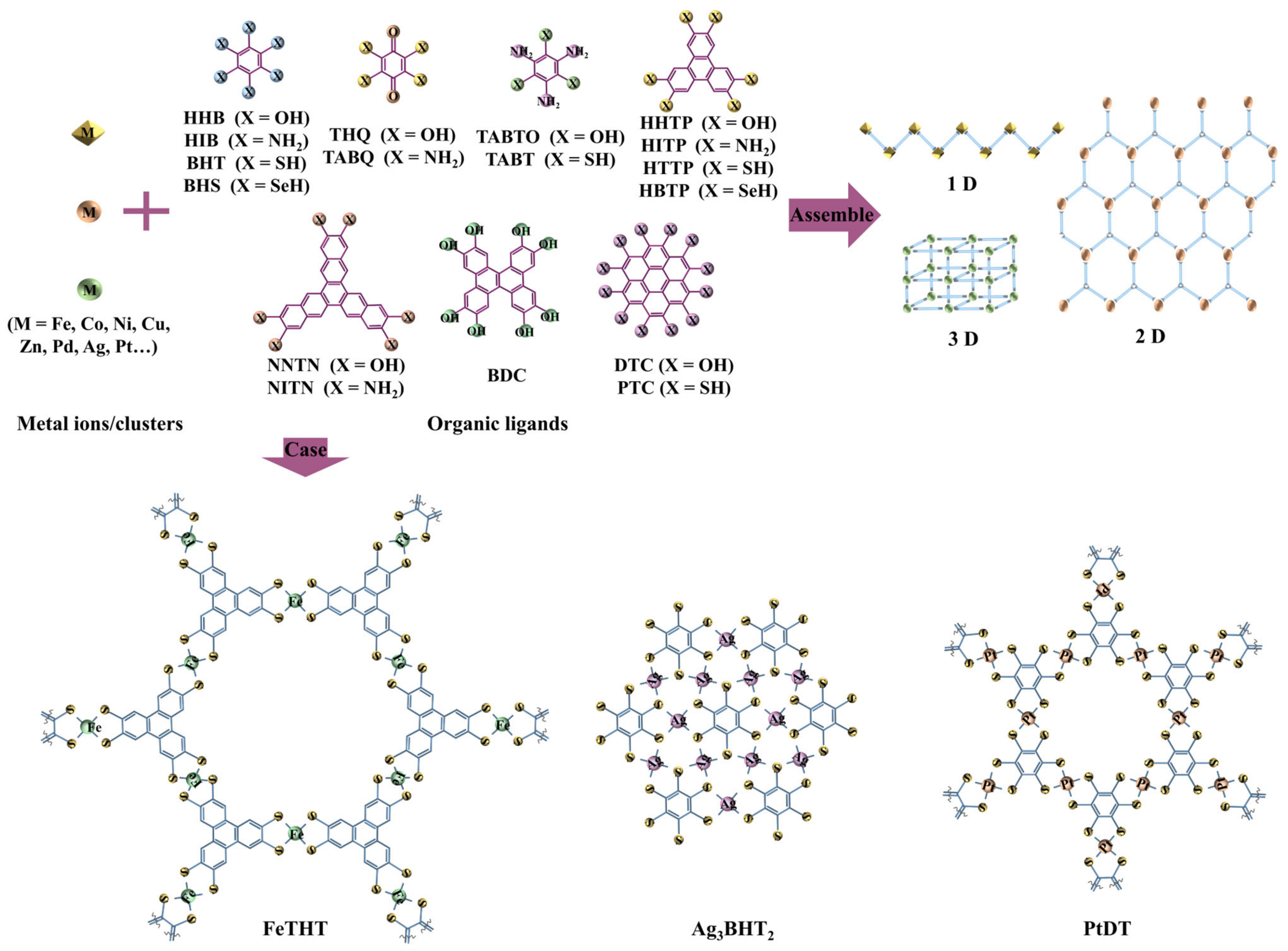
Figure 1. Schematic diagram of MOFs structure and some examples of c-MOFs.
Batteries 09 00109 g001
Figure 2. Application of c-MOFs in rechargeable lithium batteries.
Batteries 09 00109 g002
Figure 3. Time axis of c-MOFs application in lithium batteries.
Batteries 09 00109 g003
Figure 4. Three conductive mechanisms of c-MOFs.
Batteries 09 00109 g004
Figure 5. Strategies for the synthesis of c-MOFs. (a) Hydro/solvothermal synthesis, (b) the interfacial strategies for the synthesis of c-MOFs films, (c) the layer-by-layer self-assembly strategies for the synthesis of c-MOFs films.
Batteries 09 00109 g005
Figure 6. Application of c-MOFs in LIBs.
Batteries 09 00109 g006
Figure 7. (a) Structural model and (b) FESEM images of Ni–CAT, (c) three lithium storage sites of Ni–CAT located in (I) benzene ring, (II) pores, and (III) space between layers, (d) cycling performance of Ni–CAT at 0.2 and 0.5 A·g−1. Reproduced with permission from Ref. [77]. Copyright 2019 RSC. (e) Comparison of c-MOFs with some conventional carbon-based materials as anodes.
Batteries 09 00109 g007
Figure 8. (a) Crystal structure of Cu3(HHTP)2 from top and side views, (b) HR−TEM image of Cu3(HHTP)2, (c) the rate capability of Cu3(HHTP)2 at current rates from 1 C to 20 C, (d) the cycling performance of Cu3(HHTP)2 at different current rates for 500 cycles. Reproduced with permission from Ref. [83]. Copyright 2019 Elsevier B.V.
Batteries 09 00109 g008
Figure 9. (a) Synthesis process of the Cu–BHT C-MOF, (b) experimental and theoretically predicted DFT voltage curves for the Cu–BHT C-MOF cathode in the voltage range of 1.5 to 3.0 V (versus Li+/Li). Reproduced with permission from Ref. [84]. Copyright 2020 ACS. (c) Perspective view of the crystal structure of Fe(DHBQ)–(H2O)2 along the b- and a-axes. Reproduced with permission from Ref. [101]. Copyright 2021 ACS. (d) (NBu4)2Fe2(DHBQ)3 reaction mechanism during charge and discharge cycles. Reproduced with permission from Ref. [85]. Copyright 2021 ACS.
Batteries 09 00109 g009
Figure 10. Application of c-MOFs in Li–S and Li–air batteries.
Batteries 09 00109 g010
Figure 11. (a) Rate performance of Li–S batteries with PP and Ni3(HITP)2 modified separators at different current densities of 0.1, 0.2, 0.5, 1, 2 and 0.1 C. Reproduced with permission from Ref. [88]. Copyright 2019 ACS. (b) Cycling performance of S@Ni3(HITP)2-CNT cathode after 100 cycles at 0.2 C. Reproduced with permission from Ref. [90]. Copyright 2019 Wiley-VCH. (c) Rate performance of Ni–HHTP@CP cathode and Ni-BTC@CP cathode in Li–S batteries. Reproduced with permission from Ref. [91]. Copyright 2021 Elsevier B.V. (d) XPS survey spectrum of Cu–THQ NFs coated on GDE, (e) High resolution TEM image of the Li2O2 product after the 10th discharge. The corresponding fast Fourier transform (FFT) pattern is shown in the inset, (f) long-term cycling of LiǁLi symmetrical cell with current density of 0.5 mA·cm−2 and fixed capacity of capacity of 0.5 mA·h·cm−2. The inset presents the details of the voltage versus time profile towards the end of cycling. Reproduced with permission from Ref. [93]. Copyright 2022 Wiley-VCH Verlag.
Batteries 09 00109 g011
Figure 12. (a) Side view and top view of a single unit of relaxed and lithiated Cu3(HHTP)2 framework. The average potential for each lithium-ion insertion was 2.55 V, taking the lithium anode as a reference. The green, red, brown, blue, and white spheres are lithium, oxygen, carbon, copper, and hydrogen atoms, respectively. Reproduced with permission from Ref. [83]. Copyright 2019 Elsevier B.V. (b) Fully relaxed 2 × 2 crystallographic structure of the 2D Cu–BHT MOF. The numbers and letters represent different positions for Li+ adsorption. C atoms in brown, Cu atoms in blue, and S atoms in yellow, (c) total and projected density of states of the fresh Cu–BHT monolayer and 1 Li+ loaded in the essential three rings of the Cu–BHT structure. Reproduced with permission from Ref. [84]. Copyright 2020 ACS. (d) Structure evolution of TQ lithiation pathway in LIBs calculated by DFT. Reproduced with permission from Ref. [82]. Copyright 2021 John Wiley and Sons Ltd. Energy band structures and density of states (DOS) of (e) Li0.25Ga3C6N6, (f) Li4.5Ga3C6N6. The dashed red lines represent the Fermi levels. Reproduced with permission from Ref. [135]. Copyright 2022 Elsevier B.V.
Batteries 09 00109 g012
Figure 13. Further research and application of c-MOFs in other batteries.
Batteries 09 00109 g013
Table 1. Performance of c-MOFs in rechargeable lithium batteries.
c-MOFsDimensionApplicationCurrent RateCyclesCapacity (mA·h·g−1)Reference
Ni–CAT1LIBs anode0.1 A·g−1
0.2 A·g−1
0.5 A·g−1
/
200
200
889
626
592
[77]
Cu–CAT1LIBs anode0.2 A·g−1
2.0 A·g−1
320
/
646
381
[78]
Co–CAT/LIBs anode200 mA·g−1100404[79]
Si/Ni3(HITP)22LIBs anode0.1 C
1 C
100
1000
2657
876
[80]
Cu–BHT·rGO2LIBs anode100 mA·g−1
200 mA·g−1
500 mA·g−1
1000 mA·g−1
/
/
/
/
1190.4
1230.8
1131.4
898.7
[81]
Cu–HHTQ2LIBs anode600 mA·g−1200657.6[82]
Cu3(HHTP)2/LIBs cathode1 C2094.9[83]
Cu–BHT2LIBs cathode300 mA·g−1500175[84]
(NBu4)2Fe2(DHBQ)33LIBs cathode500 mA·g−1350103.1[85]
Co3(HITP)22Li–S batteries separator//762[86]
Ni3(HITP)22Li–S batteries separator1 C500716[87]
Ni3(HITP)22Li–S batteries separator0.5 C300585.4[88]
Ni–TABQ2Li–S batteries separator1 C1000820[89]
Ni3(HITP)22Li–S batteries cathode0.2 C
0.5 C
1 C
100
150
300
1302.9
807.4
629.6
[90]
Ni–HHTP@CP/Li–S batteries cathode0.2 C200910[91]
NiRu–HTP/Li–air batteries cathode500 mA·g−1200/[92]
Cu–THQ/Li–air batteries cathode1–2 A·g−1100–3001000–2000[93]
Disclaimer/Publisher’s Note: The statements, opinions and data contained in all publications are solely those of the individual author(s) and contributor(s) and not of MDPI and/or the editor(s). MDPI and/or the editor(s) disclaim responsibility for any injury to people or property resulting from any ideas, methods, instructions or products referred to in the content.