Article

Effect of Graphite Morphology on the Electrochemical and Mechanical Properties of SiOx/Graphite Composite Anode

1
National Power Battery Innovation Center, GRINM Group Corporation Limited, Beijing 100088, China
2
China Automotive Battery Research Institute Co., Ltd., Beijing 100147, China
3
General Research Institute for Nonferrous Metals, Beijing 100088, China
4
China Automotive Technology and Research Center Co., Ltd., Tianjin 300300, China
*
Authors to whom correspondence should be addressed.
Batteries 2023, 9(2), 78; https://doi.org/10.3390/batteries9020078
Submission received: 31 October 2022 / Revised: 10 January 2023 / Accepted: 20 January 2023 / Published: 24 January 2023
(This article belongs to the Special Issue Anodes for High-Performance Li-Ion Batteries)

Abstract

:
Mixing SiOx materials with graphite materials has become a key technology to improve their performance, but it is still unclear what kind of graphite materials help to construct a stable electrode structure. The purpose of this study is to explore the effect of graphite morphology on the structure and performance of SiOx/C composite electrodes (850 mAh g−1). For the SiOx/C59 composite electrode constructed by the lamellar graphite (C59) with a big aspect ratio and SiOx particles, the SiOx particles agglomerate in the pores of C59 particles. This uneven electrode structure could lead to excessive stress and strain of the electrode during cycling, which causes the anode electrode structure failure and cycling performance deterioration. While the small-size lamellar graphite (SFG15) with random orientation helps to construct stable electrode structure with uniform particle distribution and pore structure, which could reduce the stress and strain change of the electrode during cycling. Thus, the composite electrode (SiOx/SFG15) exhibits better cycling performance compared with SiOx/C59 composite electrode. This work reveals the structure-activity relationship of graphite morphology, electrode structure and the mechanical and electrochemical performance of the electrode, and provides a guide to the design and development of the high capacity SiOx/C composite electrode structure.

1. Introduction

The theoretical specific capacity (3579 mAh g−1) of silicon [1] for lithium storage at room temperature is much higher than that of commercial graphite materials (372 mAh g−1). Besides, the lithium intercalation potential of Si is slightly higher than that of graphite, which can avoid the formation of lithium dendrite and contribute to better safety performance. Therefore, Si-based materials [2] have become one of the most promising anode materials. However, the volume change (>300%) of Si materials during lithium insertion and extraction is the major limiting factor for its application. The unrestricted volume change often causes the pulverization of Si materials, the excessive growth of SEI film, and the collapse of electrode structure [3,4,5]. In order to advance the practical application of silicon in high-energy cells, researchers have carried out extensive research work.
At the material level, mixing stable graphite with Si is one of the most effective strategies to improve the cycle stability of Si-based materials, such as Si/C and SiOx/C composites [6,7,8,9]. In addition, many researchers have found that the porous electrode structure has a large impact on the performance of Si-based electrodes. The microstructural parameters of electrodes such as porosity, pore size and distribution, and electrode component distribution are the key factors to determine the performance of electrodes and cells. Thus, researchers have improved the performance of Si-based electrodes by optimizing the pore structure and designing new electrode structures. To optimize the pore structure, pore-forming agents such as NaCl [10] and PMMA (Polymethyl methacrylate) [11] were usually used to treat Si-based electrodes. The pores newly generated by pore-forming agents can accommodate the volumetric expansion of Si-based active materials, which can suppress electrode deformation and the breakdown of the electrical network. Another example is gradient electrode that is designed by increasing the porosity [12], decreasing binder [13,14] and conductive carbon [15,16] in the collector-to-separator direction. This gradient electrode can ensure the energy density of battery and improve the cycling stability. Besides, the multi-layer electrodes [17,18,19,20,21] with transition layer can buffer the stress of current collector and separator caused by the volume change of Si-based materials, and improve the stability of the electrode.
These new electrode structure designs can effectively improve the performance of silicon-based electrodes. However, they are usually too complicated for practical application. Thus, mixing Si-based materials with graphite materials has become a prominent technology to improve the performance of Si-based materials. It has been shown that the morphology and size of graphite particles have a great influence on the structure of Si-C composite electrodes, which in turn affect the electrochemical and mechanical properties of the electrode [22,23]. Regrettably, the above studies are based on Si nanomaterials. SiOx materials are considered as an ideal material to replace Si due to their small volume change and good cycling performance. To our knowledge, there have never been studies on investigating the effect of graphite morphology on SiOx. Therefore, studying the effect of graphite morphology on the performance of SiOx/C electrodes will contribute to optimize the design of SiOx/C electrodes. The purpose of this study is to investigate the effect of graphite morphology on the structure, electrochemical and mechanical properties of SiOx/C electrodes. Two kinds of graphite materials with different morphologies were selected as the research object, mixed with SiOx to prepare SiOx/C electrodes with a high specific capacity (850 mAh g−1). The two graphite materials are a higher aspect ratio and large anisotropy graphite C59 with a particle size of about 15 μm and a lamellar graphite SFG15 with a particle size of about 9 μm. The structure-activity relationship of graphite morphology, electrode structure, and the performance of the SiOx/C composite electrode is revealed. In the SiOx/C59 composite electrode, the SiOx particles agglomerate between the large-size graphite sheets. This conductive network is more easily damaged due to the expanding of the SiOx particles with local agglomeration, while the small-size graphite SFG15 with small anisotropy contributes to build a composite electrode with random and uniform particle distribution, which facilitates the construction of the stable conductive network for the composite electrode and further the improvement cycling performance of SiOx/C composite electrode. Besides, in-situ constant displacement/ pressure method [24,25,26,27,28,29,30,31,32,33,34,35] is used to study the electrode stress and strain characteristics in pouch cells. The mechanism that graphite morphology affects the stability of electrode structure and furthers the performance of electrode is revealed from the perspective of mechanics. These results show that the SiOx/C electrode constructed by small particle graphite with small anisotropy could effectively reduce the stress and strain of the electrode during the charging/discharging. Thus, small particle graphite can improve the stability of the electrode structure, and then restrain the capacity decay of the SiOx/C composite electrode upon cycling.

2. Materials and Methods

Electrode preparation: SiOx (Pre-lithiated material, Shin-Etsu Chemical Co., Ltd., TYO, Japan), the artificial graphite SFG15 (TIMCAL, Bodio, Switzerland), and C59 (Jincan Technology, Hunan, China) were used as active materials to prepare the electrode. The conductive carbons were SP (conductive carbon black, TIMCAL, Bodio, Switzerland) and CNT (single-walled carbon nanotubes, Bertrand, ShangHai, China), and the binders were CMC (carboxymethyl cellulose sodium, Sigma-Aldrich) and SBR (Styrene-butadiene, joint-stock company, Shanghai, China). The active materials, conductive carbon and the binder at a weight ratio of 90:4:6, were blended together to form a slurry. The slurry was coated on the copper foil, and then dried at 45 °C for 2 h. The dried electrode was cut into discs (14 mm in diameter), rolled to the compaction density of 1.55 g cm−3, and then dried at 100 °C for 12 h in vacuum. The mass loading of active material was 4.5 mg cm−2. The two types of SiOx/C electrodes with different graphite materials were named as SiOx/SFG15 and SiOx/C59.
Assembly and characterization of coin cells: the electrochemical performance of the as-prepared electrode was characterized in a CR2032 coin-type half-cell. Lithium foil with a diameter of 1.56 cm and a thickness of 0.45 mm (China Energy Lithium Co., Ltd., Analytical Reagent) was employed as the counter electrode and Celgard 2300 polypropylene film(Celgard, LLC, Analytical Reagent) was adopted as the separator. A total of 1 M LiPF6 in ethylene carbonate, diethyl carbonate, and methyl ethyl carbonate (EC: DEC: EMC = 1:1:1) are used as the electrolyte. The half-cell was assembled in an ultra-pure argon-filled glove box (both oxygen and water are below 0.5 ppm). Galvanostatic lithiation (discharge)/ delithiation (charge) test were carried out on a LAND CT-2001 (Wuhan LAND Electronics Co., Ltd., China). The half coin cell was discharged at a current of 0.1 C until the cutoff voltage of 0.05 V, and then discharged at a current of 0.01 C until the cutoff voltage of 0.005 V for fully lithiated. After 3 min, the half coin cell was charged at a current of 0.1 C until the cutoff voltage of 2 V.
Preparation and characterization of pouch cells: The pouch cells were assembled with the SiOx/SFG15 or SiOx/C59 as anode and LiNi0.8CO0.2Mn0.1O2(NMC811, Ningbo Ronbay Lithium Battery Material Co., Ltd., Analytical Reagent) as cathode, respectively. The NMC811 cathode is consisted of active material, conductive carbon, and binder at a weight ratio of 95.8:2.4:1.8. The conductive carbon was SP, KS-6 (TIMCAL, Bodio, Switzerland) and CNT at a weight ratio of 0.4: 0.9: 1.1, and the binder was PVDF (polyvinylidene fluoride, Solvay, Sigma-Aldrich, Analytical Reagent). The mass loading of double sides of the cathode was 41 mg cm−2, and the compacted density of the cathode was 3.5 g cm−3. The N/P ratio used for full cell was 1.05. The anode and cathode were dried in a vacuum oven at 100 °C for 24 h. The electrolyte and separator used for pouch cells were the same as the coin cells. The 2.6 Ah pouch cell was assembled in a drying chamber, with 9 cathode electrodes (76 × 54 mm) and 10 anode electrodes (79 × 56 mm). At room temperature, the 2.6 Ah pouch cell was left standing for 24 h and then pre-charged on the LAND CT-2001 test system. The pouch cell was charged for 5 h with a current of 0.02 C and 3 h with a current of 0.1 C to keep 40% SOC (state of charge). After pre-charging, the air pocket was cut off and then sealed again to eliminate the influence of gas production on the thickness of the pouch cell. The vacuum-sealed cells were separately cycled with a current of 0.2 C for the first two lithiation/delithiation cycles, and then 0.33 C for the next three cycles between 2.8 V and 4.2 V. The cycling performance for pouch cells were carried out with current of 0.33 C and 1 C for delithiation and lithiation respectively in a voltage window of 2.8–4.2 V.
Characterization of materials and electrode structure: The particle size and distribution of the material were measured by a Mastersizer 3000 model Malvern laser particle size analyzer. The specific surface area was measured with QUADRASORB (Quanta, USA). The resistivity of the powder was measured by a four-probe conductivity tester. The porosity, pore size, and pore distribution of the electrode were measured with the AUTO SCAN-33 Mercury porosimeter of Quanta Company, USA. For post-mortem analysis after the different cycles of the half coin cells, the cells were fully delithiated at 2 V with 0.1 C, and then they were disassembled in an Ar-filled glovebox. The microstructure of the SiOx/C materials and the electrodes were analyzed by Scanning electron microscope (SEM, joint-stock Company, Japan high-tech). The cross-section samples were prepared by ion-milling for 4 h in a Hitachi IM4000 plus device at an acceleration voltage of 4 kV (ion current approx. 120 μA), and then these samples were transferred into a SEM for morphological analysis.
In situ characterization of mechanical properties:
In-situ constant displacement: In the experiment, splints were used to hold the pouch cell in place, and a pressure sensor was used to record the pressure change of the pouch cell in real-time. The device is shown in Figure 1a,c, the recording time interval was 10 s, and the initial pressure was fixed at 0.19 MPa.
In-situ constant pressure: In the experiment, the constant external pressure of the pouch cell was held through the pressure sensor and the pressure cylinder realizing, and the displacement of the pouch cell was recorded in real-time by the displacement sensor. The device is shown in Figure 1b,d, the recording time interval was 10 s, and the constant pressure was fixed at 0.19 MPa.

3. Results

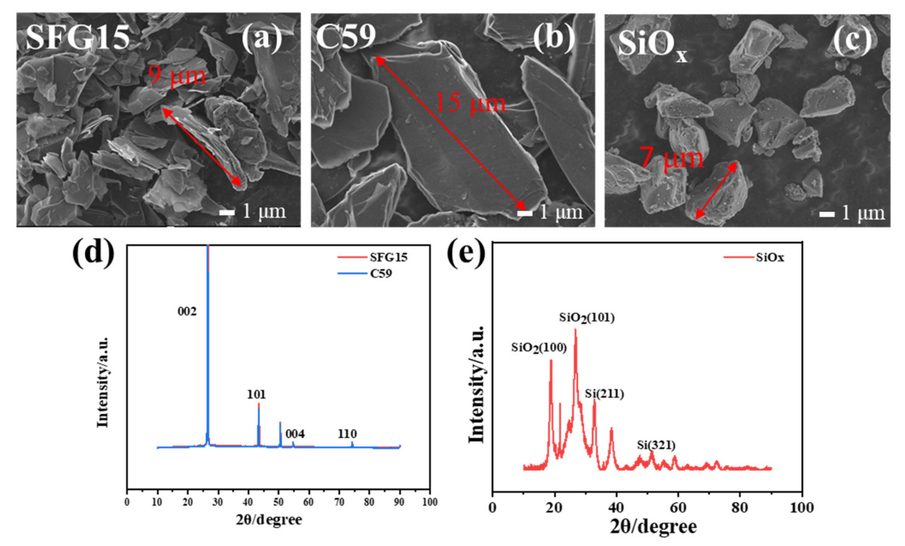
3.1. Physical-Chemical Characteristics of Graphites and SiOx

Figure 2a–c shows the SEM images of the SFG15 and C59 graphite and SiOx particles. SFG15 is thin flake graphite with a particle size of about 9 μm. C59 exhibits a higher aspect ratio and large anisotropy with a particle size of about 15 μm. The particle size of SiOx is about 7 μm. The results of the laser particle size distribution tests show that the median particle sizes D50 of SFG15, C59, and SiOx are 9.34 μm, 15.7 μm, and 7.73 μm, respectively, which is consistent with the SEM results. The physical and chemical parameters of materials are shown in Table 1. Compared with C59, SFG15 exhibits lower resistivity and higher specific surface area, resulting in higher conductivity of the electrode and the lower initial Coulombic efficiency [36]. The XRD patterns of SFG15, C59 and SiOx materials are shown in Figure 2d,e. SFG15 displays a higher diffraction peak intensity of the (101) peak compared to C59, indicating a higher crystallinity. In general, graphite with high crystallinity has low resistivity [37]. The FWHM of (002) peak in the C59 is 0.170 and that of SFG15 is 0.185. The larger the FWHM means the smaller the grain size, which is consistent with the particle size data [22]. Figure 2e shows that SiOx has sharp characteristic diffraction peaks indexed to the (211) and (321) planes of Si and (100) and (101) planes of SiO2, which indicates that the raw material of SiOx is mainly composed of SiO2 and Si.

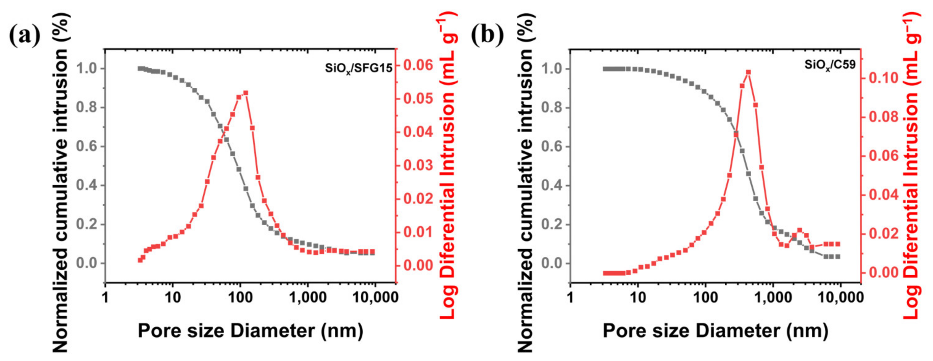
3.2. Pore Structure Characterization of SiOx/C Electrodes

The pristine SiOx/SFG15 and SiOx/C59 electrodes were tested by mercury intrusion to compare the difference of the structure, as shown in Figure 3. Normalized cumulative intrusion curves (Figure 3 black) were obtained by dividing the cumulative intrusion volume with the total intrusion volume for each sample. The SiOx/C59 electrode has a higher total invasion volume (0.082 mL g−1) compared with SiOx/SFG15 electrode. The total invasion volume is proportional to the porosity and median pore diameter. Thus, the porosity of SiOx/C59 electrode (39.05%) was larger than that of SiOx/SFG15 electrode (33.83%), and the median pore diameter of SiOx/C59 electrode (0.39 μm) was larger than that of SiOx/SFG15 electrode (0.10 μm), as shown in Table 2. This result is consistent with Jeschull et al.‘s study that small particles of graphite tend to pack uniformly and tightly [22]. Differentiated curves are used to indicate parameters such as critical, threshold, and connecting pore sizes. According to the differentiated curves (Figure 3 red), the SiOx/C59 electrode has two intrusion peaks, representing two levels of connecting pores. This indicates that the pore size distribution in the electrode is uneven. The differentiated curve of the SiOx/SFG15 electrode is more consistent with the normal distribution, showing the uniform distribution of the pore size. Our results show that the pore structure of the SiOx/C composite electrode has a strong correlation with the type of graphite.

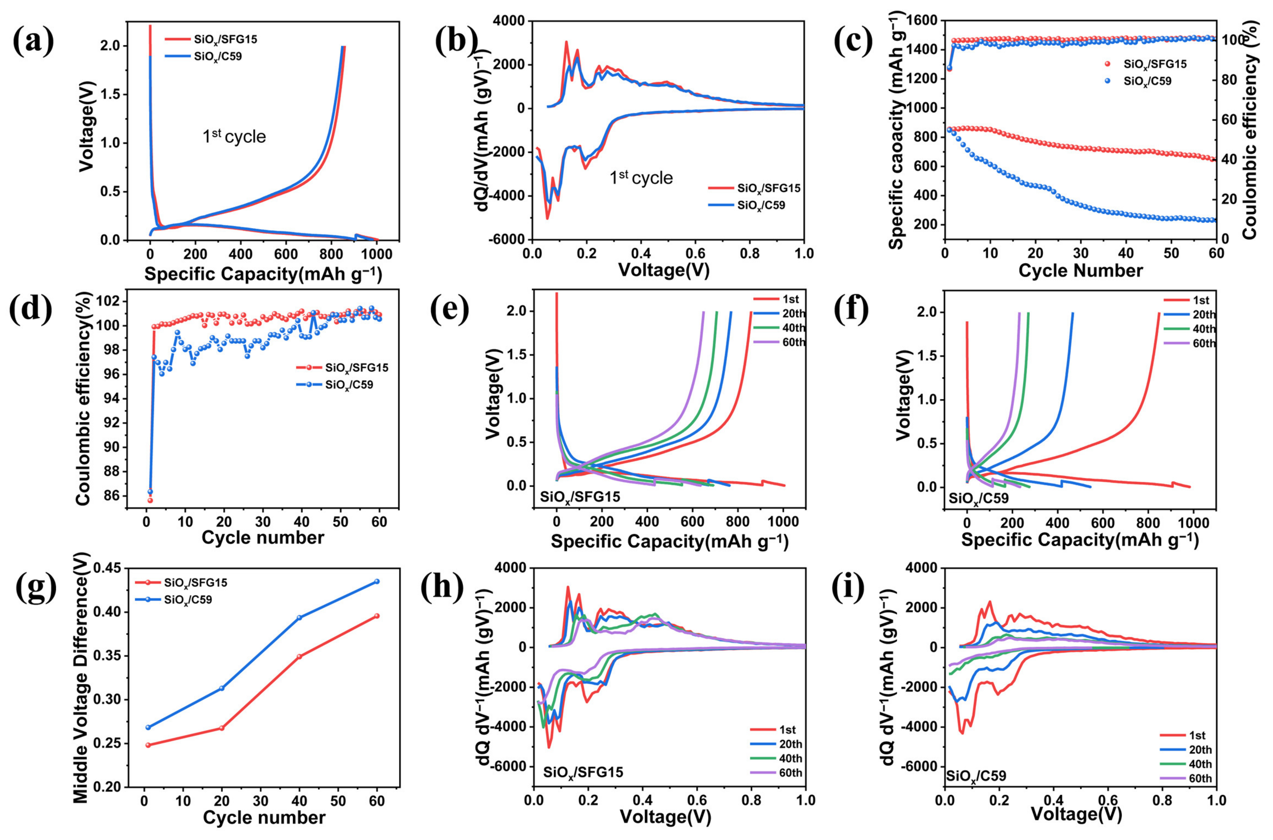
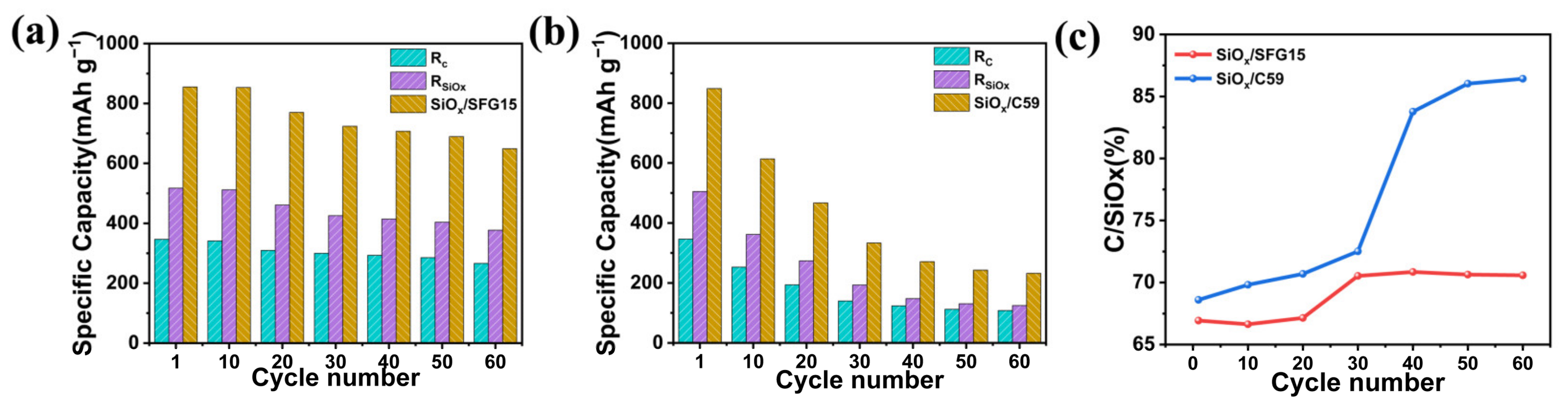
3.3. Electrochemical Performances of SiOx/C Electrodes

To explore the contribution of the graphite morphology to the electrochemical performance of the composite electrode, the two kinds of SiOx/C electrodes were cycled in half coin cells. As can be seen from the first lithiation/delithiation curves and incremental capacity (IC) curves, the two kinds of SiOx/C electrodes and the two kinds of carbon electrodes display similar characteristics of lithiation/delithiation, respectively (Figure 4a,b, Figures S1 and S3). The first delithiation specific capacities of the SiOx/C59 and SiOx/SFG15 electrode are 848.7 mAh g−1 and 858.6 mAh g−1, and the first coulombic efficiency (CE) are 86.35% and 85.62%, respectively (Figure 4d). The higher specific surface area of SFG15 graphite is the main reason for the decrease in the first coulombic efficiency, due to the larger irreversible capacity caused by the SEI formation on the electrode surface [22].
Although the SiOx/SFG15 electrode shows low initial CE, it has better cycling performance. The delithiation capacity and corresponding coulombic efficiency during cycling are plotted in Figure 4c. After 60 cycles, the specific capacity of the SiOx/C59 electrode decreases from 848.7 mAh g−1 to 231.3 mAh g−1, which is lower than graphite. The capacity retention is only 27.25%, indicating that not only the capacity of SiOx is degraded, but also part of the graphite is failed, while, SiOx/SFG15 electrode has better cycling performance. After 60 cycles, it still maintains a reversible specific capacity of 645.2 mAh g−1 with 75.15% capacity retention. The coulombic efficiency of the SiOx/SFG15 electrode reaches 99.9% in the second cycle, as shown in Figure 4d. The average coulombic efficiencies of SiOx/SFG15 and SiOx/C59 electrodes up to 60 cycles are 100.43% and 98.90%, respectively (Table 3) (The efficiency is greater than 100%, because SiOx is a pre-lithiated material). Figure 4e,f show the lithiation/delithiation curves during cycling. With the cycles, the lithiation and delithiation curves are shifted downward and upward, respectively. Meanwhile, the voltage plateaus become shorter. The high voltage plateau of the charging curve of the SiOx/C59 electrode changes significantly for the first 40 cycles. The delithiation plateau of SiOx above 0.28 V disappears, indicating almost complete failure of the SiOx active material. In addition, the middle voltage difference (denoting the differential value between the middle voltage of lithiation and the middle voltage of delithiation) increases during cycling for both two kinds of electrodes (Figure 4g). While the SiOx/C59 electrode shows larger increase rate of the middle voltage difference, so SiOx/C59 electrode exhibits a perceptibly larger voltage polarization during cycling. In order to clearly describe the capacity decay and polarization behavior, Figure 4h,i present the incremental capacity curves of the two kinds of electrodes during cycling. The lithiation and delithiation peaks are shifted downward and upward upon cycling, respectively, resulting from increaseing of the polarization of the cell. According to Figure S2a, the difference between the graphite lithiation peak (red) and the SiOx lithiation peak (blue) is indistinguishable, whereas in Figure S2b, we can clearly distinguish the delithiation peaks attributed to graphite and SiOx, the graphite lithiation peaks are below 0.28 V and the SiOx lithiation peaks are above 0.28 V. Therefore, it can be inferred that which material is the main source of capacity loss from the variation of peak strength of delithiation during the cycling. The decay rate of SiOx delithiation peak above 0.28 V is significantly higher compared with the graphite delithiation peak below 0.28 V, indicating that the electrode capacity decay mainly results from the loss of SiOx with lithium storage activity, especially in SiOx/C59 electrode.
To further estimate the capacity fade of graphite and SiOx semi-quantitatively, the delithiation profile was divided into two regions. As shown in Figure S2b, the peak area represents the specific capacity of each region. The graphite and SiOx peak area are assigned as Rc and RSiOx, respectively (as in the color-filled part), and the ratio of Rc to RSiOx are abbreviated as C/SiOx. The higher C/SiOx represents more SiOx failure. Figure 5 reveals the capacity decay of graphite and SiOx upon cycling. The C/SiOx of both electrodes slightly change at the first 20 cycles, indicating that the active material loss of graphite and SiOx occurred almost simultaneously at the initial cycling stage for both electrodes. The main difference of SiOx/SFG15 and SiOx/C59 electrode occurred after 30 cycles. The C/SiOx of the SiOx/C59 electrode increases sharply after 30 cycles, while the C/SiOx of the SiOx/SFG15 electrode remains almost constant. After 60 cycles, the C/SiOx of SiOx/SFG15 and SiOx/C59 electrodes are 70.58% and 86.43%, respectively, indicating that the deactivation of SiOx in SiOx/C59 electrode is more serious.

3.4. Analysis of Electrode Structure Changes before and after Cycling

For deep insights into the effect of the morphology of graphite on the cycling performance of the composite electrode, the surface and cross-sectional SEM images of the two kinds of electrodes before and after cycling were conducted (Figure 6). The morphology of electrodes with large differences in pore and particle distribution before cycling is shown in the surface and cross-section micrographs in Figure 6a–h. It can be seen that the pore size of the SiOx/C59 electrode is larger and has two levels of pore size, while the pore distribution of the SiOx/SFG15 electrode is uniform, which is consistent with the results of the mercury intrusion porosimetry test (Figure 6a,c). As shown in Figure 6g,h, small particles of SFG15 with little anisotropy are randomly arranged in the electrode. SiOx particles uniformly distributed around the graphite particles without obvious agglomeration (Figure 6g, red cycle). The C59 particles with a large aspect ratio tend to be arranged parallel to the current collector. SiOx particles are agglomerated in the interstices of the large graphite particles (Figure 6h, red cycle). Agglomeration may lead to large stress and strain in the electrode internal, in turn affect the cycling performance of the electrode.
The electrode structure for the two kinds of electrodes also exhibits larger difference after 60 cycles. For the SiOx/C59 electrode, the electrode surface shows obvious cracks (Figure 6j). Besides, the surface of SiOx is covered by a large number of flocculent particles (Figure 6l), indicating that the SEI underwent excessive growth. The instability and excessive growth of SEI might be the main reasons for the low coulombic efficiency and the deterioration of electrode structure during the cycling for the SiOx/C59 electrode. Unlike the SiOx/C59 electrode, the surface of the SiOx/SFG15 electrode is relatively intact (Figure 6i). Though the SiOx particles of the SiOx/SFG15 electrode gradually separated from the conductive network after cycling, the SEI film covered on the SiOx particle surface is relatively thin and dense (Figure 6k). More seriously for the SiOx/C59 electrode, part of the materials was detached from the current collector, resulting in the destroyed electron-conducting network and collapsed electrode structure (Figure 6n,p). It is noteworthy that there are some SiOx particles with particle size >12 μm in the SiOx/C59 electrode (Figure 6o), which is larger than D90 (10.5 μm). This indicates that the destruction of the conductive network of the electrode leads to incomplete lithiation/delithiation of the active material during the cycling. The thickness of the SiOx/C59 electrode increased from 41 μm to 81 μm, and the expansion ratio is 97.65%. while the thickness change of the SiOx/SFG15 electrode is relatively small after 60 cycles, increasing from 40 μm to 75 μm in an expansion ratio of 86.50% (Figure 6m,o). The structural stability of the SiOx/SFG15 electrode is improved relative to that of the SiOx/C59 electrode.
It can be inferred that the inhomogeneous distribution of particles and pore size directly leads to the inhomogeneous stress in the electrode [38]. The inhomogeneous stress would cause adverse effects on the structural stability, and then result in the poor cycling performance of the electrode. Therefore, the inhomogeneous distribution of the internal pores and the agglomeration of SiOx is one of the reasons for the poor structural stability of the SiOx/C59 electrode.

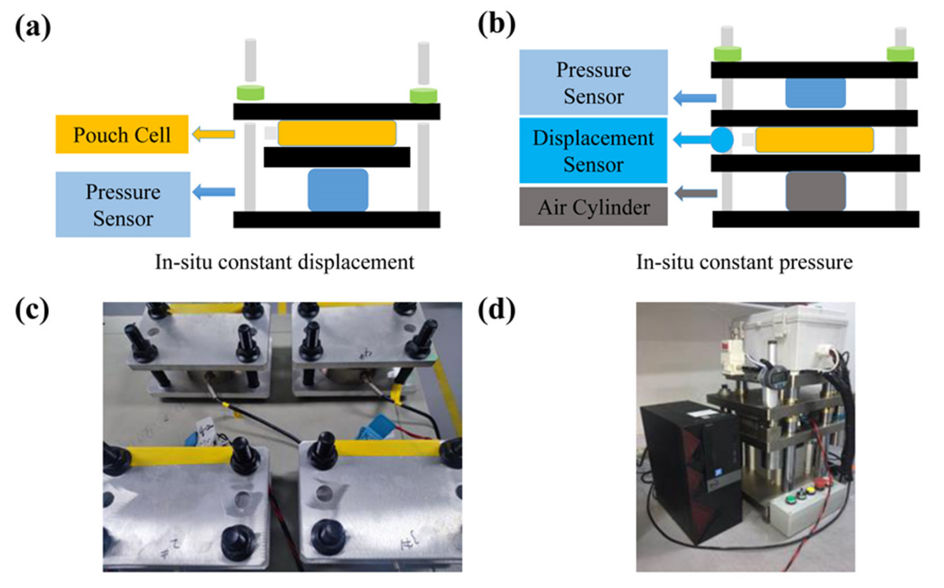
3.5. In-Situ Constant Displacement/Pressure Detection of NCM811|| SiOx/C Pouch Cells

To further investigate the effect of electrode structure on the stress and strain of SiOx/C electrodes, the stress/strain of the SiOx/C59|NCM811 and SiOx/SFG15|NCM811 pouch cells were investigated using in-situ constant displacement/pressure detection device. The initial charge/discharge behavior of SiOx/C|NCM811 pouch cells were shown in Table S1. During the charging process, the c-axis of the NCM811 cathode first increases and then decreases, and the total volume is contracting [39]. The volume contraction ratio of NCM811 cathode is about 5% according to the in-situ XRD calculation [40], which can be negligible compared with the expansion ratio of 118% for the SiOx. Therefore, the in-situ constant displacement/pressure can reflect the mechanical properties of the SiOx/C electrode during the lithiation/delithiation process. Figure 7a,b show the relative stress and height change curves of the two kinds of cells during the lithiation/delithiation, which show the similar trend (The height change information of two cells is in the Figure S4). According to the slope of the curve, the charging/discharging progress can be divided into three stages. Taking the SiOx/C59 pouch cell as an example for the charging process (Figure 7a), at stage 1, the change of pressure is small due to the low volumetric expansion of graphite particles (<10%) and the relatively low expansion of Si particles at low Li concentration. The initial lithiation of Si particles is mainly accommodated by Li insertion into interstitial sites, which does not result in significant volumetric changes of the Si structure [41]. At stage 2, the pressure grows faster with the increase in lithiation. The anode active material particles will now start to expand into the interparticle voids to accommodate the volume expansion at a fixed pouch cell volume, resulting in a gradual pressure rise and porosity reduction [42]. At stage 3, the pressure increases rapidly due to a sharp change in stress caused by particle-to-particle compression after the pores filled. For the discharging process, at stage 1, as described in Section 3.3, the delithiation potential of SiOx and graphite is different, the delithiation potential of the anode electrode for the stage of SOC 100–80% is below 0.28 V. At this stage, graphite is preferentially delithiation, and the volume changes little, so the slope of the curve is small. Stages 2 and 3 are the stages of SiOx starting to delithiation and pore recovery, respectively.
From the result of the in-situ constant displacement/pressure detection, the different graphite morphology has a direct effect on the fluctuation range of stress and strain during the charging/discharging. The relative stress variation ratio of SiOx/C59 cells during the first charging progress is 17 times higher than that of SiOx/SFG15 cells (Figure 7a). Figure 7c shows the differential curve of pressure for charging/discharging. Compared with the SiOx/SFG15 electrode (Figure 7c,d), the SiOx/C59 electrode has a wider peak width and stronger peak intensity in the second stage of charging, indicating a larger stress change caused by the reaction of SiOx. Meanwhile, the thickness change during the charging/discharging of the SiOx/C59 cell is significantly larger than the SiOx/SFG15 cell (Figure 7b).
The graphite morphology directly leads to the structural differences of the SiOx/C composite electrode. These differences could affect the electrochemical and mechanical properties of the electrode. The schematic diagram of the two electrode structures is shown in Figure 8. After the electrodes are rolled, the SFG15 graphite with smaller size and SiOx particles are randomly and uniformly dispersed in the SiOx/SFG15 electrode. While in the SiOx/C59 electrode, C59 particles are mostly arranged parallel to the current collector and SiOx particles agglomerate between graphite particles. For the SiOx/C59 electrode, the conductive network of the electrode is mostly composed of monolithic graphite-conductive carbon-SiOx agglomerates-conductive carbon-monolithic graphite. As the SiOx particles continually expand, the electrical contact between the conductive carbon and the SiOx particles is easily destroyed due to the excessive stress and strain of the electrode coming from the SiOx agglomerates upon cycling. This can directly lead to the failure of the conductive network and deactivation of the active material. After 60 cycles, the SiOx/C59 electrode collapsed more seriously (Figure 8b). More and more graphite particles and SiOx agglomerates are separated from the conducting network, resulting in the decay of electrode capacity. For the SiOx/SFG15 electrode, the conductive network is mostly composed of randomly arranged graphite-conductive carbon-SiOx-conductive carbon-randomly arranged graphite due to the uniform distribution of SFG15 graphite and SiOx particles. Even if the electrical contact between the conductive agent and the SiOx particles is broken, it will only result in the isolating of single SiOx particles, but not affect the entire conductive network. The small particle size of SFG15 graphite has lower resistivity, thus part of the randomly arranged SFG15 graphite can continue to act as a conductive carbon to connect the conductive network and maintain the stability of the structure.

4. Discussion

In this paper, the SiOx/C composite electrode was prepared by mixed SiOx with lamellar graphite SFG15 with D50 of 9.34 μm, and C59 with D50 of 15.7 μm, respectively. The structural characterization, electrochemical characterization, and in-situ mechanical characterization of the SiOx/C composite electrode reveal that the graphite morphology has a significant influence on the SiOx/C composite electrode.
(1)
The results of mercury intrusion porosimetry test and SEM show that the graphite morphology has a large effect on the structure of the composite electrode. The large-size C59 graphite particles are mixed with SiOx particles to make SiOx/C59 composite electrode, in which the SiOx particles agglomerate between the large-size graphite sheets. The conductive network in the electrode is more easily damaged due to the expanding of the SiOx particles with local agglomeration. While the small-size SFG15 graphite particles contribute to build a composite electrode with random and uniform particle distribution. This facilitates the construction of the stable conductive network for the composite electrode.
(2)
Furthermore, the difference in electrode structure affects the cycle performance of the electrode. The SiOx/C59 electrode shows poor cycling performance remaining charging specific capacity of only 231.3 mAh g−1 after 60 cycles at 0.1 C. SEM images show that the failure of the SiOx/C59 electrode structure is the main cause of the deactivation of the active material and rapid capacity decay, while, the SiOx/SFG15 electrode shows better cycling performance with charging specific capacity of 648.9 mAh g−1 after 60 cycles at 0.1 C due to its stable electrode structure.
(3)
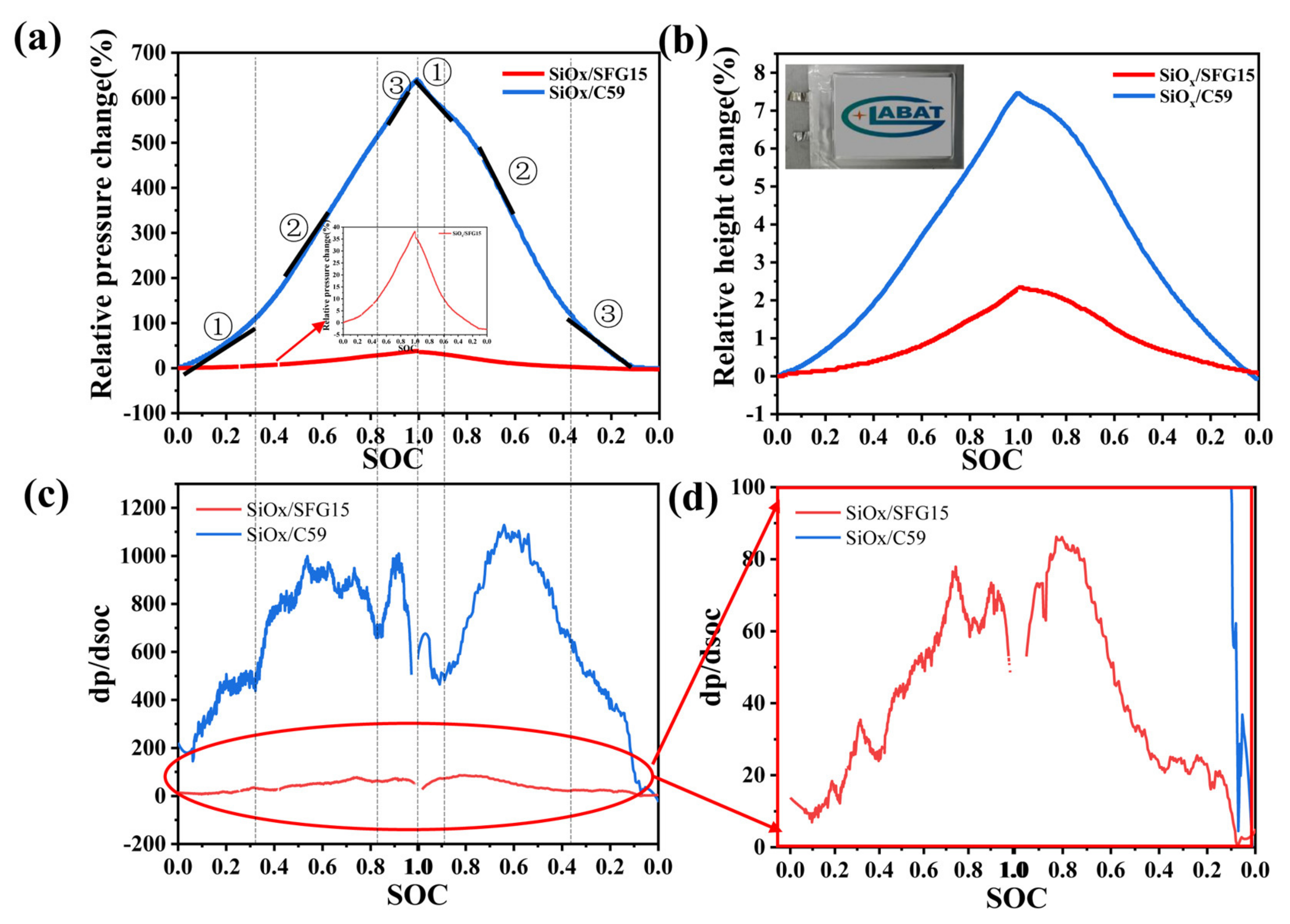
Besides, the in-situ constant displacement/pressure method was used to study the electrode stress and strain characteristics. The results show that the SiOx/C electrode constructed by small particle graphite with small anisotropy could effectively reduce the stress and strain of the electrode during the charging/discharging. Thus, small particle graphite can improve the stability of the electrode structure, and then restrain the capacity decay of the SiOx/C composite electrode upon cycling.

5. Conclusions

The effects of graphite morphology on the electrochemical performance of SiOx/C electrodes have been systematically studied and the structure-activity relationship of graphite morphology, electrode structure, and the mechanical and electrochemical performance of the electrode is revealed in this paper. As a result, compared with the lamellar graphite (C59) with a big aspect ratio, the small-size lamellar graphite (SFG15) with random orientation contributes constructing a stable electrode structure with uniform particle distribution and pore structure, which could reduce the stress and strain change of the electrode during cycling. Therefore, the composite electrode (SiOx/SFG15) exhibits better cycling performance, a reversible specific capacity of 645.2 mAh g−1 with 75.15% capacity retention, compared with 27.25% capacity retention of the SiOx/C59 electrode, after 60 cycles. In conclusion, the small-size lamellar graphite helps to construct a stable SiOx/C electrode structure, and furthermore improves the mechanical and electrochemical stability of the SiOx/C electrodes. While small graphite particles will lead to low-compaction density of the electrode and low-energy density of the battery. Therefore, various factors need to be considered comprehensively in the electrode designing according to the actual demand.

Supplementary Materials

The following supporting information can be downloaded at: https://www.mdpi.com/article/10.3390/batteries9020078/s1.

Author Contributions

Conceptualization, J.P.; methodology, X.L.; formal analysis, X.L. and Z.L.; investigation, T.M.; writing—original draft preparation, C.W.; writing—review and editing, Z.C.; All authors have read and agreed to the published version of the manuscript.

Funding

Ministry of Science and Technology of the People’s Republic of China [grant number, 2016YFB0100206], Guangdong Provincial Science and Technology Commission, Guangdong Key Areas R&D Program [grant number, 2020B0909030004] and High-safety, all-climate Power Battery and electric chassis integrated design and development [grant number, TC210H02R].

Institutional Review Board Statement

Not applicable.

Informed Consent Statement

Not applicable.

Data Availability Statement

Data is contained within the article or Supplemental Material.

Conflicts of Interest

The authors declare no conflict of interest.

References

  1. Limthongkul, P.; Jang, Y.-I.; Dudney, N.J.; Chiang, Y.-M. Electrochemically-driven solid-state amorphization in lithium-silicon alloys and implications for lithium storage. Acta Mater. 2003, 51, 1103–1113. [Google Scholar] [CrossRef]
  2. Beattie, S.D.; Loveridge, M.J.; Lain, M.J.; Ferrari, S.; Polzin, B.J.; Bhagat, R.; Dashwood, R. Understanding capacity fade in silicon based electrodes for lithium-ion batteries using three electrode cells and upper cut-off voltage studies. J. Power Sources 2016, 302, 426–430. [Google Scholar] [CrossRef] [Green Version]
  3. Zuo, X.; Zhu, J.; Müller-Buschbaum, P.; Cheng, Y.-J. Silicon based lithium-ion battery anodes: A chronicle perspective review. Nano Energy 2017, 31, 113–143. [Google Scholar] [CrossRef]
  4. Sun, Y.; Liu, N.; Cui, Y. Promises and challenges of nanomaterials for lithium-based rechargeable batteries. Nat. Energy 2016, 1, 16071. [Google Scholar] [CrossRef]
  5. Kasavajjula, U.; Wang, C.; Appleby, A.J. Nano- and bulk-silicon-based insertion anodes for lithium-ion secondary cells. J. Power Sources 2007, 163, 1003–1039. [Google Scholar] [CrossRef]
  6. Zhang, J.; Liang, Y.; Zhou, Q.; Peng, Y.; Yang, H. Enhancing electrochemical properties of silicon-graphite anodes by the introduction of cobalt for lithium-ion batteries. J. Power Sources 2015, 290, 71–79. [Google Scholar] [CrossRef]
  7. Xu, Q.; Li, J.-Y.; Sun, J.-K.; Yin, Y.-X.; Wan, L.-J.; Guo, Y.-G. Watermelon-Inspired Si/C Microspheres with Hierarchical Buffer Structures for Densely Compacted Lithium-Ion Battery Anodes. Adv. Energy Mater. 2017, 7, 1601481. [Google Scholar] [CrossRef]
  8. Kim, S.Y.; Lee, J.; Kim, B.H.; Kim, Y.J.; Yang, K.S.; Park, M.S. Facile Synthesis of Carbon-Coated Silicon/Graphite Spherical Composites for High-Performance Lithium-Ion Batteries. ACS Appl. Mater. Interfaces 2016, 8, 12109–12117. [Google Scholar] [CrossRef]
  9. Ko, M.; Chae, S.; Ma, J.; Kim, N.; Lee, H.-W.; Cui, Y.; Cho, J. Scalable synthesis of silicon-nanolayer-embedded graphite for high-energy lithium-ion batteries. Nat. Energy 2016, 1, 16113. [Google Scholar] [CrossRef]
  10. Zhao, H.; Yang, Q.; Yuca, N.; Ling, M.; Higa, K.; Battaglia, V.S.; Parkinson, D.Y.; Srinivasan, V.; Liu, G. A Convenient and Versatile Method To Control the Electrode Microstructure toward High-Energy Lithium-Ion Batteries. Nano Lett. 2016, 16, 4686–4690. [Google Scholar] [CrossRef] [Green Version]
  11. Jeong, G.; Lee, S.M.; Choi, N.S.; Kim, Y.-U.; Lee, C.K. Stabilizing dimensional changes in Si-based composite electrodes by controlling the electrode porosity: An in situ electrochemical dilatometric study. Electrochim. Acta 2011, 56, 5095–5101. [Google Scholar] [CrossRef]
  12. Bitsch, B.; Gallasch, T.; Schroeder, M.; Börner, M.; Winter, M.; Willenbacher, N. Capillary suspensions as beneficial formulation concept for high energy density Li-ion battery electrodes. J. Power Sources 2016, 328, 114–123. [Google Scholar] [CrossRef]
  13. Diehm, R.; Kumberg, J.; Dörrer, C.; Müller, M.; Bauer, W.; Scharfer, P.; Schabel, W. In Situ Investigations of Simultaneous Two-Layer Slot Die Coating of Component-Graded Anodes for Improved High-Energy Li-Ion Batteries. Energy Technol. 2020, 8, 1901251. [Google Scholar] [CrossRef]
  14. Liu, D.; Chen, L.-C.; Liu, T.-J.; Chu, W.-B.; Tiu, C. Improvement of Lithium-Ion Battery Performance by Two-Layered Slot-Die Coating Operation. Energy Technol. 2017, 5, 1235–1241. [Google Scholar] [CrossRef]
  15. Chen, L.-C.; Liu, D.; Liu, T.-J.; Tiu, C.; Yang, C.-R.; Chu, W.-B.; Wan, C.-C. Improvement of lithium-ion battery performance using a two-layered cathode by simultaneous slot-die coating. J. Energy Storage 2016, 5, 156–162. [Google Scholar] [CrossRef]
  16. Liu, T.; Li, X.; Sun, S.; Sun, X.; Cao, F.; Ohsaka, T.; Wu, J. Analysis of the relationship between vertical imparity distribution of conductive additive and electrochemical behaviors in lithium ion batteries. Electrochim. Acta 2018, 269, 422–428. [Google Scholar] [CrossRef]
  17. Guo, Z.; Zhou, L.; Yao, H. Improving the electrochemical performance of Si-based anode via gradient Si concentration. Mater. Des. 2019, 177, 107851. [Google Scholar] [CrossRef]
  18. Xu, Y.; Yin, G.; Cheng, X.; Zuo, P. Enhanced lithium storage performance of silicon anode via fabricating into sandwich electrode. Electrochim. Acta 2011, 56, 4403–4407. [Google Scholar] [CrossRef]
  19. Yang, Z.; Xia, Y.; Ji, J.; Qiu, B.; Zhang, K.; Liu, Z. Superior cycling performance of a sandwich structure Si/C anode for lithium ion batteries. RSC Adv. 2016, 6, 12107–12113. [Google Scholar] [CrossRef]
  20. Huang, C.; Kim, A.; Chung, D.J.; Park, E.; Young, N.P.; Jurkschat, K.; Kim, H.; Grant, P.S. Multiscale Engineered Si/SiO x Nanocomposite Electrodes for Lithium-Ion Batteries Using Layer-by-Layer Spray Deposition. ACS Appl. Mater. Interfaces 2018, 10, 15624–15633. [Google Scholar] [CrossRef]
  21. Wu, J.; Qin, X.; Zhang, H.; He, Y.-B.; Li, B.; Ke, L.; Lv, W.; Du, H.; Yang, Q.-H.; Kang, F. Multilayered silicon embedded porous carbon/graphene hybrid film as a high performance anode. Carbon 2015, 84, 434–443. [Google Scholar] [CrossRef]
  22. Jeschull, F.; Surace, Y.; Zürcher, S.; Lari, G.; Spahr, M.E.; Novák, P.; Trabesinger, S. Graphite Particle-Size Induced Morphological and Performance Changes of Graphite–Silicon Electrodes. J. Electrochem. Soc. 2020, 167, 100535. [Google Scholar] [CrossRef]
  23. Gómez-Cámer, J.L.; Bünzli, C.; Hantel, M.M.; Poux, T.; Novák, P. On the correlation between electrode expansion and cycling stability of graphite/Si electrodes for Li-ion batteries. Carbon 2016, 105, 42–51. [Google Scholar] [CrossRef]
  24. Rieger, B.; Schlueter, S.; Erhard, S.V.; Schmalz, J.; Reinhart, G.; Jossen, A. Multi-scale investigation of thickness changes in a commercial pouch type lithium-ion battery. J. Energy Storage 2016, 6, 213–221. [Google Scholar] [CrossRef]
  25. Oh, K.-Y.; Siegel, J.B.; Secondo, L.; Kim, S.U.; Samad, N.A.; Qin, J.; Anderson, D.; Garikipati, K.; Knobloch, A.; Epureanu, B.I.; et al. Rate dependence of swelling in lithium-ion cells. J. Power Sources 2014, 267, 197–202. [Google Scholar] [CrossRef]
  26. Wagner, M.R.; Raimann, P.R.; Trifonova, A.; Moller, K.C.; Besenhard, J.O.; Winter, M. Dilatometric and mass spectrometric investigations on lithium ion battery anode materials. Anal. Bioanal. Chem. 2004, 379, 272–276. [Google Scholar] [CrossRef]
  27. Hahn, M.; Buqa, H.; Ruch, P.; Goers, D.; Spahr, M.; Ufheil, J.; Nova, P.; Kotz, R. A Dilatometric Study of Lithium Intercalation into Powder-Type Graphite Electrodes. Electrochem. Solid State 2008, 11, A151. [Google Scholar] [CrossRef]
  28. Gómez Cámer, J.L.; Morales, J.; Sánchez, L.; Ruch, P.; Ng, S.H.; Kötz, R.; Novák, P. Nanosized Si/cellulose fiber/carbon composites as high capacity anodes for lithium-ion batteries: A galvanostatic and dilatometric study. Electrochim. Acta 2009, 54, 6713–6717. [Google Scholar] [CrossRef]
  29. Louli, A.J.; Li, J.; Trussler, S.; Fell, C.R.; Dahn, J.R. Volume, Pressure and Thickness Evolution of Li-Ion Pouch Cells with Silicon-Composite Negative Electrodes. J. Electrochem. Soc. 2017, 164, A2689–A2696. [Google Scholar] [CrossRef]
  30. Park, S.; Kim, T.; Oh, S.M. Electrochemical Dilatometry Study on Si-Embedded Carbon Nanotube Powder Electrodes. Electrochem. Solid-State Lett. 2007, 10, A142. [Google Scholar] [CrossRef]
  31. Hwang, S.S.; Cho, C.G.; Kim, H. Polymer microsphere embedded Si/graphite composite anode material for lithium rechargeable battery. Electrochim. Acta 2010, 55, 3236–3239. [Google Scholar] [CrossRef]
  32. Berckmans, G.; De Sutter, L.; Marinaro, M.; Smekens, J.; Jaguemont, J.; Wohlfahrt-Mehrens, M.; van Mierlo, J.; Omar, N. Analysis of the effect of applying external mechanical pressure on next generation silicon alloy lithium-ion cells. Electrochim. Acta 2019, 306, 387–395. [Google Scholar] [CrossRef]
  33. De Sutter, L.; Berckmans, G.; Marinaro, M.; Wohlfahrt-Mehrens, M.; Berecibar, M.; Van Mierlo, J. Mechanical behavior of Silicon-Graphite pouch cells under external compressive load: Implications and opportunities for battery pack design. J. Power Sources 2020, 451, 227774. [Google Scholar] [CrossRef]
  34. Choi, Y.H.; Lim, H.K.; Seo, J.-H.; Shin, W.J.; Choi, J.H.; Park, J.H. Development of Standardized Battery Pack for Next-Generation PHEVs in Considering the Effect of External Pressure on Lithium-Ion Pouch Cells. SAE Int. J. Altern. Powertrains 2018, 7, 195–205. [Google Scholar] [CrossRef]
  35. Wu, H.; Huang, Y.; Yang, Y.; Fu, H.; Sun, X.; Ding, X. Insight into the electrochemical behavior of lithium-sulfur cells assisted by potassium hydroxide activated carbon black and polyaniline nanorods. Electrochim. Acta 2016, 209, 643–653. [Google Scholar] [CrossRef]
  36. Buqa, H.; Würsig, A.; Vetter, J.; Spahr, M.E.; Krumeich, F.; Novák, P. SEI film formation on highly crystalline graphitic materials in lithium-ion batteries. J. Power Sources 2006, 153, 385–390. [Google Scholar] [CrossRef]
  37. Dudley, J.T.; Wilkinson, D.P.; Thomas, G.; LeVae, R.; Woo, S.; Blom, H.; Dahn, J.R. Conductivity of electrolytes for rechargeable lithium batteries. J. Power Sources 1991, 35, 59–82. [Google Scholar] [CrossRef]
  38. Oumellal, Y.; Delpuech, N.; Mazouzi, D.; Dupré, N.; Gaubicher, J.; Moreau, P.; Soudan, P.; Lestriez, B.; Guyomard, D. The failure mechanism of nano-sized Si-based negative electrodes for lithium ion batteries. J. Mater. Chem. 2011, 21, 6201–6208. [Google Scholar] [CrossRef]
  39. Zhao, K.-J.; Li, Y.-G.; Brassart, L. Pressure-sensitive plasticity of lithiated silicon in Li-ion batteries. Acta Mech. Sin. 2013, 29, 379–387. [Google Scholar] [CrossRef]
  40. Pan, K.; Zou, F.; Canova, M.; Zhu, Y.; Kim, J.-H. Systematic electrochemical characterizations of Si and SiO anodes for high-capacity Li-Ion batteries. J. Power Sources 2019, 413, 20–28. [Google Scholar] [CrossRef]
  41. Zhao, K.; Tritsaris, G.A.; Pharr, M.; Wang, W.L.; Okeke, O.; Suo, Z.; Vlassak, J.J.; Kaxiras, E. Reactive flow in silicon electrodes assisted by the insertion of lithium. Nano Lett 2012, 12, 4397–4403. [Google Scholar] [CrossRef] [PubMed]
  42. Huang, S.; Zhu, T. Atomistic mechanisms of lithium insertion in amorphous silicon. J. Power Sources 2011, 196, 3664–3668. [Google Scholar] [CrossRef]
Figure 1. Schematic diagrams and photos of in-situ mechanics device; (a,c) In-situ constant displacement; (b,d) In-situ constant pressure.
Batteries 09 00078 g001
Figure 2. SEM images of the materials: (a) SFG15; (b) C59; (c) SiOx; XRD patterns of the materials: (d) graphites; (e) SiOx.
Batteries 09 00078 g002
Figure 3. Pore size distribution curves of SiOx/C electrodes, (a) SiOx/SFG15; (b) SiOx/C59.
Batteries 09 00078 g003
Figure 4. Cycling behavior of the SiOx/C half coin cells. (a,e,f) Lithiation/delithiation profiles under various cycles; (b,h,i) Incremental capacity curves under various cycles; (c,d) Cycling stability and CE values; (g) Middle voltage difference curves upon cycling.
Batteries 09 00078 g004
Figure 5. Decay curves of SiOx/C electrode (a) change of Rc, RSiOx in SiOx/SFG15 electrode; (b) change of Rc, RSiOx in SiOx/C59 electrode; (c) C/SiOx specific capacity ratio.
Batteries 09 00078 g005
Figure 6. SEM images of SiOx/C electrode before cycling: (ad) surface SEM; (eh) cross-section SEM. After 60 cycles: (il) surface SEM; (mp) cross-section SEM.
Batteries 09 00078 g006
Figure 7. Mechanical curves of two cells (a) relative stress curve; (b) relative height curve; (c) differential pressure curves; (d) detail of differential pressure curves of SiOx/SFG15.
Batteries 09 00078 g007
Figure 8. Schematic diagram of SiOx/C electrode structure changes, (a) before and after rolling; (b) before and after cycling.
Batteries 09 00078 g008
Table 1. Particle size, specific surface area, tap density, and resistivity of materials.
D10 (μm)D50 (μm)D90 (μm)Specific Surface Area (m2 g−1)Tap Density g cm−3Resistivity Ω·cm
SFG154.769.3415.78.7570.2120.14 × 103
C597.7915.726.31.5250.9402.41 × 103
SiOx4.137.7310.51.7910.202
Table 2. Porosity, total intrusion, and median pore diameter of SiOx/C electrodes.
Porosity (%)Total
Intrusion Volume (mL/g)
Median
Proe Diameter (μm)
SiOx/SFG1533.830.0590.10
SiOx/C5939.050.0820.39
Table 3. Cycle data of SiOx/C half coin cells.
First Lithiation Specific Capacity (mAh g−1)First Delithiation
Specific Capacity (mAh g−1)
First Coulombic Efficiency
(%)
60 Cycles Capacity Retention
(%)
Average Coulombic Efficiency
(%)
SiOx/SFG151002.8858.685.6275.15100.43
SiOx/C59982.8848.786.3527.2598.90
Disclaimer/Publisher’s Note: The statements, opinions and data contained in all publications are solely those of the individual author(s) and contributor(s) and not of MDPI and/or the editor(s). MDPI and/or the editor(s) disclaim responsibility for any injury to people or property resulting from any ideas, methods, instructions or products referred to in the content.

