Article

Improving Interfaces in All-Solid-State Supercapacitors Using Polymer-Added Activated Carbon Electrodes

1
Department of Physics, BITS Pilani-Pilani Campus, Rajasthan 333031, India
2
Department of Chemistry, BITS Pilani-Pilani Campus, Rajasthan 333031, India
*
Author to whom correspondence should be addressed.
Batteries 2023, 9(2), 81; https://doi.org/10.3390/batteries9020081
Submission received: 14 December 2022 / Revised: 21 January 2023 / Accepted: 24 January 2023 / Published: 25 January 2023
(This article belongs to the Special Issue Solid-State Electrolytes for Safe Batteries)

Abstract

:
Solvent-free all-solid-state supercapacitors have recently received attention. Despite their highly specific capacitance, they suffer issues related to the solid–solid interface that degrade their performance during prolonged cycling. Here, we propose a novel strategy for improving the electrode–electrolyte interface by introducing a small amount of polymer into the activated carbon-based electrode. An electrode composition of 80AC:8SA:7AB:5[PEO0.95 (LiClO4)0.05]—where AC, SA, and AB stand for activated carbon, sodium alginate binder, and acetylene black, respectively—is optimized. A composite membrane—viz., PEO-LiClO4 reinforced with 38 wt% NASICON structured nano crystallites of Li1.3Al0.3Ti1.7(PO4)3—is used as a solid electrolyte. Incorporating a small amount of salt-in-polymer (95PEO-5 LiClO4) in the electrode matrix leads to a smooth interface formation, thereby improving the performance parameters of the all-solid-state supercapacitors (ASSCs). A typical supercapacitor with a polymer-incorporated electrode exhibits a specific capacitance of ~102 Fg−1 at a discharge current of 1.5 Ag−1 and an operating voltage of 2 V near room temperature. These ASSCs also exhibit relatively better galvanostatic charge–discharge cycling, coulombic efficiency, specific energy, and power in comparison to those based on conventional activated carbon.

1. Introduction

The development of solvent/liquid-free solid-state energy devices has been gaining momentum over recent years [1,2]. Conventional electric double-layer supercapacitors use high surface area activated carbon-based electrodes [3], primarily based on liquid/gel electrolytes with high ionic conductivity. The aqueous nature of the electrolyte also provides good interfacial contacts that lead to low contact resistance, remarkable coulombic efficiency, specific energy, and specific power—making them suitable for commercial applications. Despite these advantages, supercapacitors (and also batteries) with liquid/gel electrolytes are highly prone to corrosion, leakage issues, short-circuiting, poor mechanical strength, and flexibility constraints for foldable and stretchable smart devices [4].
For the electric double layer [5], as well as pseudo capacitors [6], electrode properties play an important role [3]. There have been several attempts to engineer electrode properties emphasizing particular issues, e.g., (i) smooth interfaces, (ii) device resistance, (iii) device flexibility, (iv) effective utilization of the electrode surface area, and (v) role of inactive agents, i.e., binders. Significant work has been carried out towards the effective use of carbon-based materials in supercapacitors [3]. Electrodes based on a reduced graphene oxide sheet coated with a conducting polymer have been reported [7]. Such a composite formation resulted in improved device performance, attributed to both the electric double layer and pseudo capacitance. In another interesting work, natural cellulose has been used as an inactive electrode binder; the supercapacitor fabricated using these novel electrodes displayed appreciable thermal stability and improved cell performance parameters, viz., specific capacitance and cycling [8]. Furthermore, cherry flower waste-derived activated carbon with self-doped nitrogen has also been reported; supercapacitors using this novel electrode exhibit high specific capacitance and about ~96% capacity retention after ~38,000 cycles [9]. Similarly, flexible carbon-based electrodes have also received attention. Flexible free-standing supercapacitors have recently been prepared using a combination of graphene quantum dots and carbon cloth [10]. Electrode properties have also been altered by coating a dielectric film with atomic layer deposition [11], which improved its electrochemical performance. Recently, flexible all-solid-state-supercapacitors have also been developed using a novel graphene foam/polypyrrole composite. Such engineered electrodes lead to high capacitance [12]. Interestingly, heterostructure-based electrodes have also been used for supercapacitors. The activated carbon, assembled with FeS2/TiO2 heterostructures, has shown the potential to enhance the ion/electron migration rate and to promote surface reaction kinetics [13]. Despite their excellent performance, most supercapacitors still use organic liquids, acids, or gel-based electrolytes. Their operation temperature range is, thus, limited [14].
Solid-state ionic devices use ‘liquid-free’ fast ionic solids as electrolytes. Despite high ionic conductivity in many of these ionic solids, tailoring the properties of the interface is quite challenging. There has been significant work on solid electrolyte-based all-solid-state batteries (ASSBs) [1,15] in the last three decades. Along the same lines, all-solid-state supercapacitors (ASSCs) [16] have now started getting attention [12,17]. There have been continuous efforts to develop suitable solid electrolytes in the last few decades with (i) conductivity comparable to those of liquids/gels, and (ii) a wide electrochemical stability window. Particularly, due to their high ionic conductivity near room temperature, NASICONs—e.g., Na3Zr2Si2PO12 (NZSP) [18]—and NASICON-structured Li+ ion conductors—e.g., LiTi2(PO4)3 (LTP) [19], Li1.3Al0.3Ti1.7(PO4)3 (LATP) [20], and Li6.4La3Zr1.4Ta0.6O12 (LLZTO) [21], along with their composites with polymer salt complexes [22,23]—have been considered promising for solid ionic devices [24]. The device performance is however limited due to the electrode–electrolyte (solid–solid) interface. Many ionic ceramics have been synthesized with high ionic conductivity, but unlike gels, their contact with the electrode does not provide adequate wettability at the interface. Realizing the fact that interfacial stability is an important issue, different strategies have been adopted to tailor electrode–electrolyte interfaces, such as (i) insertion of suitable ionic liquids between the surfaces [25], (ii) application of short-duration, high-voltage pulses to poorly formed interfaces [26], and (iii) coating the electrodes with an oxide barrier layer [27].
For improving the interface, a flexible composite solid polymer electrolyte (CSPE) membrane with high ionic conductivity is the obvious choice. High ionic conductivity in CSPEs is achieved by optimizing the salt content and adding plasticizers or nano-size active/passive filler particles into the matrix. Solvent/liquid-free all-solid-state supercapacitors (ASSC) have recently been developed [28] with appreciably high capacitance using solid electrolyte membranes reinforced with NaTi2(PO4)3 (NTP) [29] and LATP nano crystallites [19]. In these active (conductive) filler-based polymers, the conductivity at ambient temperatures exhibits a notably high value ≥10−4 S cm−1. Using a Li+ ion-conducting polymer membrane with a moderate LATP content, Sharma et al. [28] recently reported ASSCs with a specific capacitance ~42 Fg−1 at ~40 °C for a membrane composition of 10LiTFSI_90(PEO0.6 LATP0.4). Ceramic polymer composite films with high LATP contents (≥60 wt%) have also been developed with polymer occupying the space between the LATP grains. ASSCs with these ‘polymer-in-ceramic’ membranes have demonstrated a high specific capacitance of ~108 Fg−1 near room temperature [17]. In a similar work, a Na+ ion PEO-NaCF3SO3 membrane dispersed with a large amount of NZSP has been used as an electrolyte in ASSCs; a high specific capacitance of ~150 Fg−1 was reported [30], with a stable cycling performance.
The performance of such polymer–ceramic hybrid membrane-based supercapacitors is promising and can be further improved, provided the solid electrode–electrolyte interface is systematically engineered. Ion penetration to the interior of electrodes and to the pores of activated carbon has been limited so far due to poor wettability, because of which, the major electrode (activated carbon) area remains unutilized [31].
This work discusses a new strategy to improve the interfacial solid–solid contacts in supercapacitors. A small amount of polymer (with salt) is added to the electrodes to improve the electrode–solid electrolyte interface. Here we report interesting findings on Li+ ion CSPE-based all-solid-state supercapacitors whose performance is dramatically improved by adding a small amount of ion-conducting polymer (PEO-LiClO4) in high surface area (800 m2 g−1) activated carbon-based electrodes. A PEO-LiClO4 solid polymer electrolyte membrane reinforced with LATP nanoparticles is used as a solid electrolyte; it is thus ensured that the polymer (PEO) and mobile salt ions (Li+, ClO4) maintain a continuity at the interface. This study presents a comparative investigation of ASSCs based on polymer-added and polymer-free activated carbon-based electrodes.

2. Materials and Methods

2.1. Solid Electrolyte Membrane Synthesis

Firstly, the NASICON structured Li1.3Al0.3Ti1.7(PO4)3 (LATP) was prepared by the solid-state reaction route, as discussed elsewhere [19]. Using a planetary ball mill (Fritsch-6), the LATP crystallite size was reduced to ~30 nm, as described earlier [28,29,32]. The LATP-polymer nano composite was prepared by a ball mill-assisted route [33]. Host polymer Polyethylene oxide (PEO; M.W. 300,000 g mol−1), nanocrystalline LATP, and LiClO4 were taken in a composition weight ratio of 5LiClO4_95(PEO0.6 LATP0.4) and mechanically ball milled in acetonitrile media. The obtained slurry was further dried and hot-pressed to obtain a freestanding homogeneous flexible film of thickness ~0.2 mm for ASSC fabrication. The composite membrane (with 38 wt% LATP) is hereafter abbreviated as 40LATP in the discussion.

2.2. ASSC Fabrication

For the preparation of the electrodes, activated carbon (AC; Merck) with a surface area ~800 m2 g−1, acetylene black (AB), and a binder sodium alginate (SA) were taken. The surface area and pore size of activated carbon were measured with a BET surface area analyzer (BELSORP MINI X) [28]. Various compositions were prepared using polymer SA, AB, and activated carbon. For the optimized composition, an electrode without polymer was chosen with a composition of 80AC:10SA:10AB and was abbreviated as ACE. Furthermore, for salt-polymer-added electrodes—used for comparison—the amount of activated carbon was fixed to 80 wt% and the polymer (with salt) was added to the matrix, substituting the AB and SA binder. Thus, the composition 80AC:8SA:7AB:5P—where P represents PEO0.95_(LiClO4)0.05—was synthesized and abbreviated as P-ACE.
In the electrode fabrication process, AC, AB, and SA were first thoroughly mixed in the deionized water medium. Furthermore, PEO and LiClO4 were also separately dissolved in deionized water. Both the solutions were separately stirred for ~6 h and slowly blended into each other. After stirring for ~8 h, the thick slurry was then cast on a 0.5 mm-thick graphite (current collector) sheet using the doctor blade technique [34]. These coated sheets were then annealed at 100 °C for ~12 h to evaporate the residual solvent. Electrodes of a circular shape (diameter ~15 mm) were cut and further used in the cell fabrication.
As a next step, ASSCs were fabricated by sandwiching the free-standing CSPE membrane between the as-prepared electrodes in a geometry of Cu|Electrode|CSPE|Electrode|Cu. The whole assembly was laminated using a hot-roll-laminator operating at 80 °C to establish good interfacial contacts. The fabricated ASSCs were characterized at 40 °C in a two-electrode configuration using an electrochemical workstation AUTOLAB M204. The electrochemical performance of the cells was examined by CV (Cyclic Voltammetry), GCD (Galvanostatic Charging–Discharging), and EIS (Electrochemical Impedance Spectroscopy). Prior to cell fabrication, the electrodes and electrolyte membrane were characterized using Field Emission Scanning Electron Microscopy (FESEM) using an FEI APREO S instrument.

3. Results and Discussion

Figure 1 shows the schematic diagram of the strategy adopted in the present work for establishing a smooth solid–solid interface. During the electrode fabrication process, the salt-added-polymer reached the grain interior and also occupied some of the pores of the activated carbon; it therefore acted as a coupling agent between the electrode and the CSPE membrane for ion exchange. This strategy was formulated with a conviction that the polymer existing in the electrode was likely to (i) facilitate the long-range diffusion of ions across the interface while charging–discharging, (ii) improve the effective contact area of the interface, and (iii) substantially decrease the interfacial polarization and enable mobile ions to reach to the activated carbon pores. Such a substitution is likely to improve the electrochemical performance of the supercapacitor.
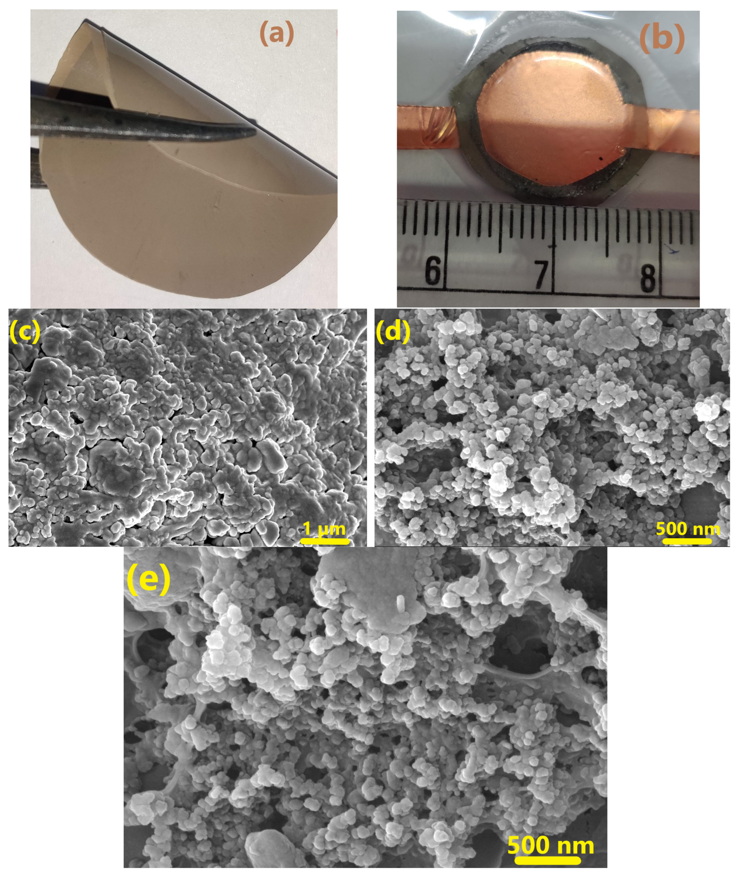
The photographs of the as-prepared CSPE membrane and the ASSC fabricated using P-ACE electrodes are shown in Figure 2a,b, respectively. The electrolyte membrane is of uniform thickness and shows good flexibility.
FESEM images of the electrolyte membrane and electrodes are shown in Figure 2c–e, respectively. Embedded crystallites (LATP) of a uniform size were apparent in the polymer matrix. The distribution of activated carbon on the electrode (Figure 2d) was quite homogeneous and the pores appeared evenly distributed. Upon insertion of polymer into the electrode matrix (Figure 2e), no agglomeration/phase segregation was evident. The polymer phase was also seen to uniformly occupy the voids and spaces between the grains.
Electrochemical impedance spectroscopy (EIS) studies (0.1 mHz to 1 MHz at 40 °C) on the as-fabricated ASSCs were performed to investigate the charge storage mechanism and to estimate the device resistance. Figure 3a depicts the Nyquist Plots for ASSCs with different electrode compositions, i.e., ACE and P-ACE. The equivalent series resistance (ESR) provides information about the overall resistive contributions, viz., from the bulk of the electrolyte or from the contact and charge transfer resistance across the interface [35]. Both the cells showed very nominal charge-transfer resistance, as the diameter of the semicircle at high frequencies was quite small. The ESR, as shown in the inset (Figure 3a), was comparable for the cell with ACE electrodes.
Furthermore, the frequency dependence of the real (Z′) and imaginary (Z″) parts of impedance have been used to obtain the real and imaginary components of capacitance, i.e., (C′ = Z ( ω ) ω | Z ( ω ) | 2   ) and (C″ = Z ( ω ) ω | Z ( ω ) | 2   ), respectively [36]. The C″-ω curve exhibits a relaxation peak attributed to a relaxation time ( τ = 2 π ω m a x ) for ions to cross the electrode–electrolyte interface and reach the pores of the activated carbon [37]. At this peak, the real component of the capacitance (C′) exhibits an inflection. For the cell with the ACE and P-ACE electrodes, C′ and C″ vs. frequency are plotted in Figure 3b and its inset, respectively. The cell with P-ACE exhibited a higher relaxation frequency and thus a relatively smaller relaxation time (~14 s) in comparison to that of the cell with the P-ACE electrodes (~33 s). These results strongly suggest that the polymer addition in the electrode enabled a faster relaxation process.
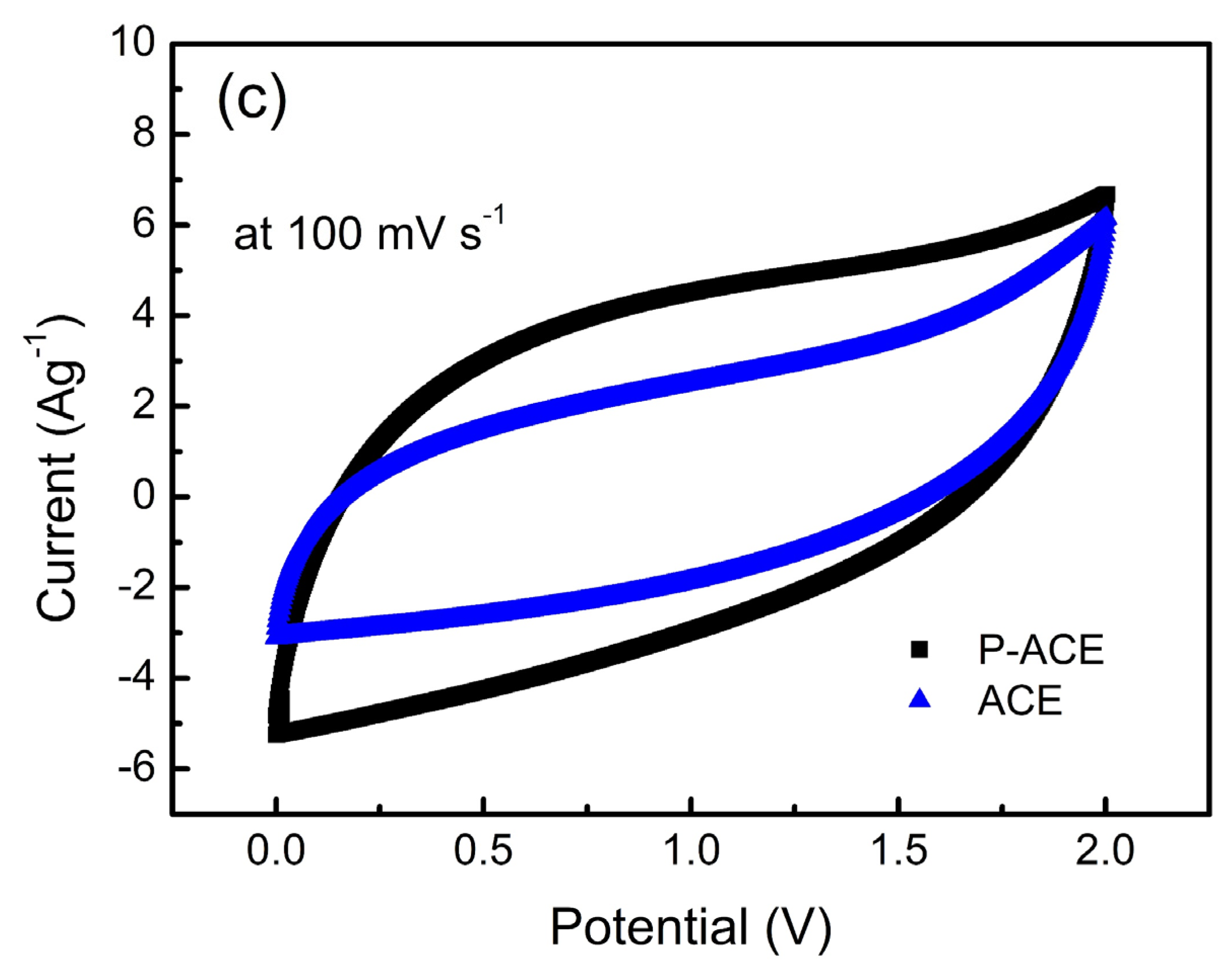
The cyclic voltammetry patterns of the ACE and P-ACE-based ASSCs were investigated within a potential window of 0–2 V and compared in Figure 3c. The patterns are nearly rectangular, without any peak-like features, and indicate the predominant electric double-layered nature of both the ASSCs. It is well known that the charge storage ability, and hence the capacitance, is proportional to the area enclosed by the CV pattern [38]. For the cell with the P-ACE electrodes, the box-like nature was more prominently seen with a relatively larger area under the curve. Apparently, the polymer incorporation into the electrode matrix led to a substantial improvement in the charge storage ability.
The galvanostatic charge–discharge (GCD) cycles were further studied and the performance parameters of the ASSCs were also obtained. The total capacitance of the device [36] C = ( I Δ t Δ V ) was calculated from the discharge current (I), discharge time (Δt), and discharge voltage (ΔV) without considering the IR drop. The specific capacitance ( C S = 4 C m t o t a l )     of the electrode [39] was thus obtained. Furthermore, the specific energy (   E = C ( Δ V 2 ) 7.2 m t o t a l   ) and specific power (   P = 3600 × E Δ t   ) were calculated in Wh kg−1 and W kg−1 [40], respectively. Additionally, the equivalent series resistance [35] ( E S R = V I R 2 I ) of the device was again estimated from the IR voltage drop during the discharge cycle. Furthermore, the coulombic efficiency (ɛ) was calculated using the ratio of discharging to charging time during the GCD cycle [41].
Figure 4a illustrates the GCD profiles for the cells with the ACE and P-ACE electrodes at a constant current of 1mA (~1.5 Ag−1). A relatively longer discharge time was seen for the ASSCs with the P-ACE electrodes. The charge–discharge curves show an almost symmetric nature, although with a slight curvature. These suggest a predominant contribution of an electric double layer at the interface, with some possibility of a pseudo-capacitive mechanism of charge storage [42]. Evidently, the presence of polymer in the electrode matrix improved the specific capacitance (Cs) notably.
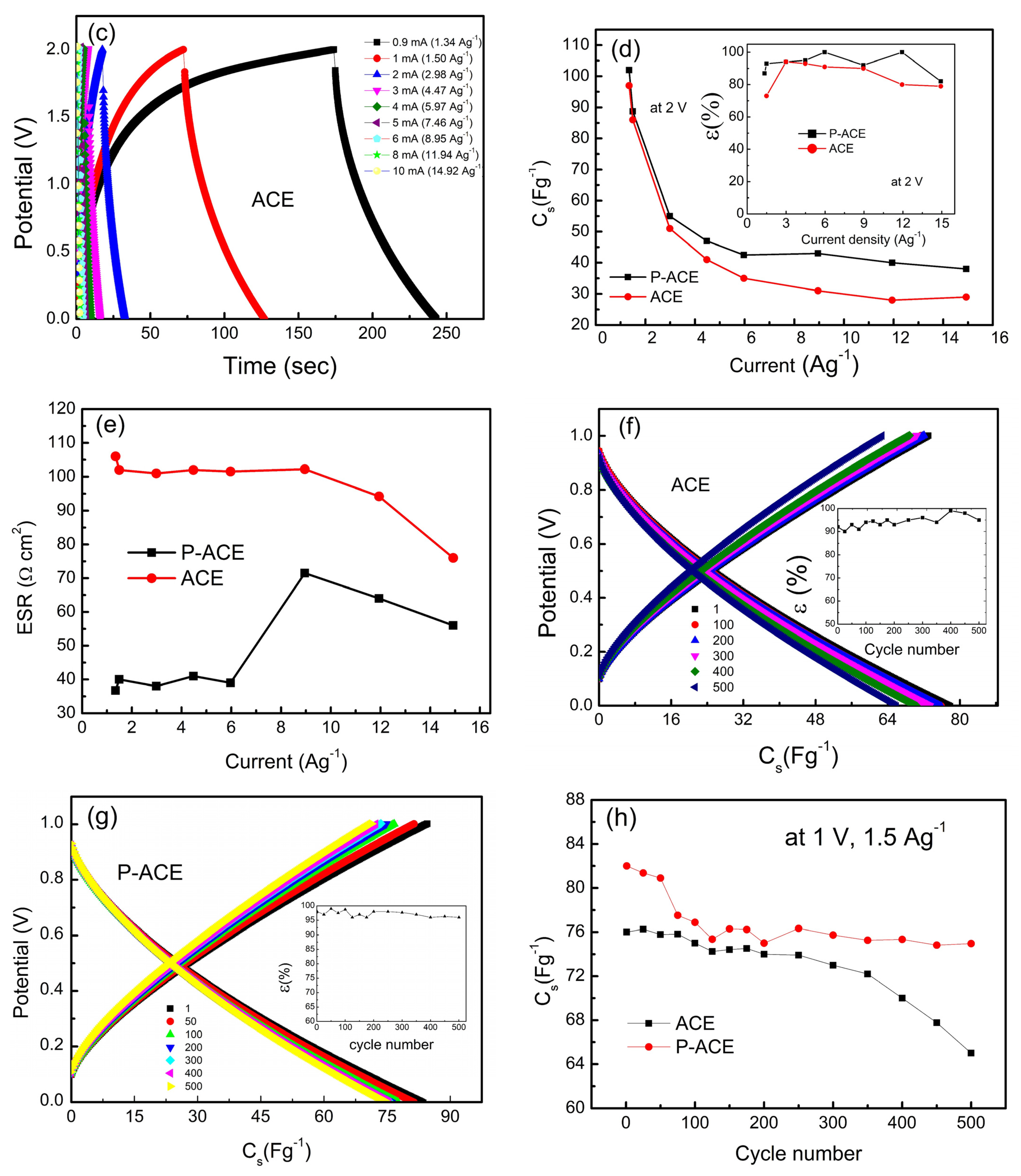
GCD curves were also obtained at different current densities, as shown in Figure 4b,c. At lower discharge currents, the GCD curves deviated from the expected triangular shape, suggestive of partial pseudo nature. For higher discharge currents, a triangular shape in the GCD profile was apparent that readily suggests the electric double-layer-type nature of the capacitance. The Cs values from the GCD curves (Figure 4b,c) obtained at different discharge current densities are plotted in Figure 4d. As can be seen, high specific capacitance values were obtained at lower current densities. Furthermore, the Cs value exhibited a gradual drop up to 4 Ag−1 and was saturated at subsequent current densities. The initial fall may be attributed to a substantial increase in the ESR value at higher currents. The Cs values corresponding to the P-ACE electrodes however saturated at a relatively higher value. The inset of Figure 4d shows the coulombic efficiency as a function of the discharge current. The efficiency was consistently higher for the ASSC with the P-ACE electrodes. Furthermore, the ESR value was found to be substantially lower for the P-ACE-based ASSCs (Figure 4e). The results accordingly suggest that the polymer at the interface (i) provides pathways for mobile ions reach to the surface and pores of the activated carbon and (ii) improves the contact area. The presence of polymer thus enables better utilization of the activated carbon surface and pores. Furthermore, the CV curves, along with EIS and GCD cycles, complement each other and suggest a typical electrostatic process of charge storage. The central mechanism of charge storage appears predominantly due to the electrosorption of mobile ions on the electrode surface due to electrostatic attraction. There is no evidence of chemical reactions at the interface in any of the above three basic measurements.
The first 500 charge–discharge cycles at 1 mA (1.5 Ag−1) and an operating voltage of 1 V are shown for the ASSCs with the ACE and P-ACE electrodes. The cycles remained truly symmetric and exhibited a high coulombic efficiency (Inset: Figure 4f,g). As shown in Figure 4f, for the cell with the P-ACE, the Cs value fell from ~78 Fg−1 to ~65 Fg−1, showing an ~83% capacity retention. In comparison, the performance of the P-ACE-based ASSC was found to be superior; it exhibited ~91% capacity retention (Figure 4g) as the capacitance dropped from a value of ~82 to 75 Fg−1 in 500 cycles.
Specific capacitance (Cs) versus cycle number is plotted in Figure 4h. The cell with the ACE electrodes exhibited a relatively low value; it remained almost constant up to ~350 cycles and then fell gradually in later cycles. On the other hand, in the case of the cell with the P-ACE electrodes, the Cs value was relatively high; it showed a subtle fluctuation up to 200 cycles and then subsequently stabilized to ~79 Fg−1 for later cycles. Possibly, due to polymer addition in the electrode matrix, it takes a few cycles for the mobile ions to form pathways for transport into the electrode matrix and the pores. A higher and stable value of Cs again suggests that the polymer in the electrode matrix enabled the active material and its pores to be more accessible to the mobile ions of the electrolyte. The specific energy for the P-ACE and ACE–based ASSCs was found to be ~12.4 Wh kg−1 and ~10.4 Wh kg−1, respectively. Furthermore, the specific power was found to be 718 W kg−1 and 697 W kg−1 for the cell with the P-ACE and ACE, respectively. The above results on all-solid-state supercapacitors are comparable to (or even higher than) some of the gel-based supercapacitors reported earlier [34,38,43].
It is interesting to compare the performance parameters of the optimized composition with the other electrode compositions reported in Table 1. As is evident, increasing polymer in the matrix (65 P-ACE and 65 ACE) leads to an increase in the ESR. A large content of polymer at the interface is thus not desired. Another composition where polymer was in a moderate amount (75 P-ACE) exhibited a good Cs value, but poor coulombic efficiency. A low content of polymer (~5 wt%) appears to be adequate for improving electrode properties.
Finally, Table 2 presents other strategies adopted for modifying electrodes/the electrode–electrolyte interface. Most of the approaches show substantial improvements in cell performance properties after engineering the electrodes. The novelty of the present work lies in the fact that it deals with a solid–solid interface that was substantially improved by introducing polymer into the electrode matrix. Thus, this is a useful approach for developing supercapacitors with solid electrolytes.

4. Conclusions and Future Perspectives

The present investigation demonstrates that the addition of a small amount of polymer into an electrode notably improves the performance of all-solid-state supercapacitors. Investigations revealed that polymer in such small amounts occupied the electrode matrix quite uniformly. Furthermore, its incorporation into the activated carbon matrix did not lead to any additional parasitic reactions and pseudo-capacitance at the interface. The electrode-electrolyte contact area improved notably, as suggested by the notably low ESR values in the GCD cycles. The charge storage time at the interface also decreased due to the presence of polymer in the electrode matrix. The study revealed that such a substitution led to a higher charge storage ability, coulombic efficiency, specific energy, and specific power; this is indeed apparent in a wide range of discharge currents.
The present study suggests that polymer addition is an efficient route for engineering electrodes—particularly when the electrolyte is a solvent-free solid polymer. In this preliminary investigation, the potential of such composite electrodes in ASSCs was demonstrated. A generalized plausible mechanism of energy storage requires more sophisticated test methods. It will also be interesting to explore redox (pseudo) solid-state supercapacitors based on polymer-dispersed electrodes. The authors are of the conviction that with a higher surface area activated carbon added with polymer, one can achieve a superior performance in ASSCs.

Author Contributions

Conceptualization, Methodology, Validation, Formal analysis, Investigation, Writing—original draft, S.S.; Formal analysis, G.K.; Conceptualization, Validation, Writing—review & editing, Funding acquisition, A.D. All authors have read and agreed to the published version of the manuscript.

Funding

This research was funded by core research grant (CRG/2019/001442), and DST-FIST grant (SR/FST/PS-1/20187/30) of Department of Science and Technology, Government of India.

Institutional Review Board Statement

Not applicable.

Informed Consent Statement

Not applicable.

Data Availability Statement

The data presented in this study are available upon request from the corresponding author.

Acknowledgments

The authors gratefully acknowledge the funding from the Department of Science and Technology, Government of India. S.S. would like to thank the DST, Govt of India for the fellowship.

Conflicts of Interest

The authors declare no conflict of interest.

References

  1. Li, C.; Wang, Z.Y.; He, Z.J.; Li, Y.J.; Mao, J.; Dai, K.H.; Yan, C.; Zheng, J.C. An advance review of solid-state battery: Challenges, progress and prospects. Sustain. Mater. Technol. 2021, 29, e00297. [Google Scholar] [CrossRef]
  2. Lu, X.; Yu, M.; Wang, G.; Tong, Y.; Li, Y. Flexible solid-state supercapacitors: Design, fabrication and applications. Energy Environ. Sci. 2014, 7, 2160–2181. [Google Scholar] [CrossRef]
  3. Olabi, A.; Abbas, Q.; Abdelkareem, M.; Alami, A.; Mirzaeian, M.; Sayed, E. Carbon-Based Materials for Supercapacitors: Recent Progress, Challenges and Barriers. Batteries 2023, 9, 19. [Google Scholar] [CrossRef]
  4. Alipoori, S.; Mazinani, S.; Aboutalebi, S.; Sharif, F. Review of PVA-based gel polymer electrolytes in flexible solid-state supercapacitors: Opportunities and challenges. J. Energy Storage 2020, 27, 101072. [Google Scholar] [CrossRef]
  5. Sharma, P.; Bhatti, T. A review on electrochemical double-layer capacitors. Energy Convers. Manag. 2010, 51, 2901–2912. [Google Scholar] [CrossRef]
  6. Simon, P.; Gogotsi, Y. Materials for electrochemical capacitors. Nanosci. Technol. A Collect. Rev. Nat. J. 2009, 7, 320–329. [Google Scholar] [CrossRef] [Green Version]
  7. Zhang, J.; Zhao, X. Conducting polymers directly coated on reduced graphene oxide sheets as high-performance supercapacitor electrodes. J. Phys. Chem. C 2012, 116, 5420–5426. [Google Scholar] [CrossRef]
  8. Böckenfeld, N.; Jeong, S.; Winter, M.; Passerini, S.; Balducci, A. Natural, cheap and environmentally friendly binder for supercapacitors. J. Power Sources 2013, 221, 14–20. [Google Scholar] [CrossRef]
  9. Bhattarai, R.; Chhetri, K.; Natarajan, S.; Saud, S.; Kim, S.; Mok, Y. Activated carbon derived from cherry flower biowaste with a self-doped heteroatom and large specific surface area for supercapacitor and sodium-ion battery applications. Chemosphere 2022, 303, 135290. [Google Scholar] [CrossRef]
  10. Tjandra, R.; Liu, W.; Zhang, M.; Yu, A. All-carbon flexible supercapacitors based on electrophoretic deposition of graphene quantum dots on carbon cloth. J. Power Sources 2019, 438, 227009. [Google Scholar] [CrossRef]
  11. Bai, Y.; Li, N.; Yang, C.; Wu, X.; Yang, H.; Chen, W.; Li, H.; Zhao, B.; Wang, P.; Han, X. Realizing high-voltage and ultralong-life supercapacitors by a universal interfacial engineering strategy. J. Power Sources 2021, 510, 230406. [Google Scholar] [CrossRef]
  12. Ren, J.; Ren, R.; Lv, Y. Stretchable all-solid-state supercapacitors based on highly conductive polypyrrole-coated graphene foam. Chem. Eng. J. 2018, 349, 111–118. [Google Scholar] [CrossRef]
  13. Xiao, X.; Duan, X.; Song, Z.; Deng, X.; Deng, W.; Hou, H.; Zheng, R.; Zou, G.; Ji, X. High-Throughput Production of Cheap Mineral-Based Heterostructures for High Power. Adv. Funct. Mater. 2022, 32, 202110476. [Google Scholar] [CrossRef]
  14. Ulihin, A.; Mateyshina, Y.; Uvarov, N. All-solid-state asymmetric supercapacitors with solid composite electrolytes. Solid State Ion. 2013, 251, 62–65. [Google Scholar] [CrossRef]
  15. Ma, J.; Wang, Z.; Wu, J.; Gu, Z.; Xin, X.; Yao, X. In Situ Solidified Gel Polymer Electrolytes for Stable Solid-State Lithium Batteries at High Temperatures. Batteries 2023, 9, 28. [Google Scholar] [CrossRef]
  16. Asl, M.S.; Hadi, R.; Salehghadimi, L.; Tabrizi, A.G.; Farhoudian, S.; Babapoor, A.; Pahlevani, M. Flexible all-solid-state supercapacitors with high capacitance, long cycle life, and wide operational potential window: Recent progress and future perspectives. J. Energy Storage 2022, 50, 104223. [Google Scholar] [CrossRef]
  17. Sharma, S.; Dalvi, A. Solid polymer electrolyte membranes using the “polymer-in-ceramic” approach for all-solid-state supercapacitor applications. Solid State Ion. 2022, 387, 116063. [Google Scholar] [CrossRef]
  18. Singh, M.D.; Dalvi, A.; Phase, D. Novel Na3Zr2Si2PO12–polymer hybrid composites with high ionic conductivity for solid-state ionic devices. Mater. Lett. 2020, 262, 127022. [Google Scholar] [CrossRef]
  19. Sharma, N.; Dalvi, A. Mechanical milling assisted synthesis of novel LiTi2(PO4)3-glass-ceramic nanocomposites. J. Non-Cryst. Solids 2018, 483, 126–133. [Google Scholar] [CrossRef]
  20. Kwatek, K.; Nowiński, J. Electrical properties of LiTi2(PO4)3 and Li1.3Al0.3Ti1.7(PO4)3 solid electrolytes containing ionic liquid. Solid State Ion. 2017, 302, 54–60. [Google Scholar] [CrossRef]
  21. Cheng, S.H.-S.; He, K.-Q.; Liu, Y.; Zha, J.-W.; Kamruzzaman, M.; Ma, R.L.-W.; Dang, Z.-M.; Li, R.K.; Chung, C. Electrochemical performance of all-solid-state lithium batteries using inorganic lithium garnets particulate reinforced PEO/LiClO4 electrolyte. Electrochim. Acta 2017, 253, 430–438. [Google Scholar] [CrossRef]
  22. Chen, L.; Li, Y.; Li, S.-P.; Fan, L.-Z.; Nan, C.-W.; Goodenough, J.B. PEO/garnet composite electrolytes for solid-state lithium batteries: From “ceramic-in-polymer” to “polymer-in-ceramic”. Nano Energy 2018, 46, 176–184. [Google Scholar] [CrossRef]
  23. Dalvi, A.; Singh, M.D.; Nayak, B.; Choudhury, B.; Sarit, A. Li+-NASICON crystallites in PEO-LiCF3SO3 matrix Characterization of a novel hybrid electrolyte. Solid State Ionics 2017, 311, 20–25. [Google Scholar] [CrossRef]
  24. Zhang, Q.; Liu, K.; Ding, F.; Liu, X. Recent advances in solid polymer electrolytes for lithium batteries. Nano Res. 2017, 10, 4139–4174. [Google Scholar] [CrossRef]
  25. Kaur, G.; Sivasubramanian, S.C.; Dalvi, A. Solid-state supercapacitors using ionic liquid dispersed Li+-NASICONs as electrolytes. Electrochim. Acta 2022, 434, 141311. [Google Scholar] [CrossRef]
  26. Parejiya, A.; Amin, R.; Dixit, M.; Essehli, R.; Jafta, C.; Wood, D.; Belharouak, I. Improving Contact Impedance via Electrochemical Pulses Applied to Lithium-Solid Electrolyte Interface in Solid-State Batteries. ACS Energy Lett. 2021, 6, 3669–3675. [Google Scholar] [CrossRef]
  27. Richards, W.D.; Miara, L.J.; Wang, Y.; Kim, J.C.; Ceder, G. Interface Stability in Solid-State Batteries. Chem. Mater. 2016, 28, 266–273. [Google Scholar] [CrossRef] [Green Version]
  28. Sharma, S.; Singh, M.; Dalvi, A. All-solid-state electric double layer supercapacitors using Li1.3Al0.3Ti1.7(PO4)3 reinforced solid polymer electrolyte. J. Energy Storage 2022, 49, 104178. [Google Scholar] [CrossRef]
  29. Singh, M.; Dalvi, A.; Phase, D.; Kumar, Y. Materials composites: Assessment of enhanced Li + ion transport and potential for solid-state supercapacitor applications. J. Mater. Sci. 2020, 55, 3951–3963. [Google Scholar] [CrossRef]
  30. Neha; Dalvi, A. Fast ionic PEO-NaCF3SO3-Na3Zr2Si2P3O12 membranes for all-solid-state energy storage devices. Mater. Sci. Eng. B Solid-State Mater. Adv. Technol. 2023, 289, 116252. [Google Scholar] [CrossRef]
  31. Ma, W.; Chen, S.; Yang, S.; Chen, W.; Weng, W.; Zhu, M. Bottom-Up Fabrication of Activated Carbon Fiber for All-Solid-State Supercapacitor with Excellent Electrochemical Performance. ACS Appl. Mater. Interfaces 2016, 8, 14622–14627. [Google Scholar] [CrossRef]
  32. Singh, M.D.; Dalvi, A. Ionic transport in NASICON-polymer hybrids: An assessment using X-ray photoelectron spectroscopy. Appl. Surf. Sci. 2021, 536, 147792. [Google Scholar] [CrossRef]
  33. Aono, H.; Sato, M.; Traversa, E.; Sakamoto, M.; Sadaoka, Y. Design of ceramic materials for chemical sensors: Effect of SmFeO3 processing on surface and electrical properties. J. Am. Ceram. Soc. 2001, 84, 341–347. [Google Scholar] [CrossRef]
  34. Tiruye, G.A.; Muñoz-Torrero, D.; Palma, J.; Anderson, M.; Marcilla, R. All-solid state supercapacitors operating at 3.5 V by using ionic liquid based polymer electrolytes. J. Power Sources 2015, 279, 472–480. [Google Scholar] [CrossRef]
  35. Vicentini, R.; Da Silva, L.; Cecilio, E.; Alves, T.; Nunes, W.; Zanin, H. How to measure and calculate equivalent series resistance of electric double-layer capacitors. Molecules 2019, 24, 1452. [Google Scholar] [CrossRef] [Green Version]
  36. Yadav, N.; Singh, M.; Yadav, N.; Hashmi, S. High performance quasi-solid-state supercapacitors with peanut-shell- derived porous carbon. J. Power Sources 2018, 402, 133–146. [Google Scholar] [CrossRef]
  37. Bhat, Y.; Yadav, N.; Hashmi, S. Pinecone-derived porous activated carbon for high performance all-solid-state electrical double layer capacitors fabricated with flexible gel polymer electrolytes. Electrochim. Acta 2019, 304, 94–108. [Google Scholar] [CrossRef]
  38. Tripathi, S.; Kumar, A.; Hashmi, S. Electrochemical redox supercapacitors using PVdF-HFP based gel electrolytes and polypyrrole as conducting polymer electrode. Solid State Ion. 2006, 177, 2979–2985. [Google Scholar] [CrossRef]
  39. Zhong, X.; Tang, J.; Cao, L.; Kong, W.; Sun, Z.; Cheng, H. Cross-linking of polymer and ionic liquid as high-performance gel electrolyte for fl exible solid-state supercapacitors. Electrochim. Acta 2017, 244, 112–118. [Google Scholar] [CrossRef]
  40. Pandey, G.P.; Kumar, Y.; Hashmi, S. Ionic liquid incorporated PEO based polymer electrolyte for electrical double layer capacitors: A comparative study with lithium and magnesium systems. Solid State Ion. 2011, 190, 93–98. [Google Scholar] [CrossRef]
  41. Hashmi, S.A.; Latham, R.J.; Linford, R.G.; Schlindwein, W.S. Polymer Electrolyte Based Solid State Redox Supercapacitors with Poly(3-Methyl Thiophene)and Polypyrrole Conducting Polymer Electrodes. Ionics 1997, 3, 177–183. [Google Scholar] [CrossRef]
  42. Lim, C.-S.; Teoh, K.H.; Liew, C.-W.; Ramesh, S. Electric double layer capacitor based on activated carbon electrode and biodegradable composite polymer electrolyte. Ionics 2014, 20, 251–258. [Google Scholar] [CrossRef]
  43. Jang, H.S.; Raj, C.J.; Lee, W.-G.; Kim, B.C.; Yu, K.H. Enhanced supercapacitive performances of functionalized activated carbon in novel gel polymer electrolytes with ionic liquid redox-mediated poly(vinyl alcohol)/phosphoric acid. RSC Adv. 2016, 6, 75376–75383. [Google Scholar] [CrossRef]
  44. Lota, G.; Tyczkowski, J.; Kapica, R.; Lota, K.; Frackowiak, E. Carbon materials modified by plasma treatment as electrodes for supercapacitors. J. Power Sources 2010, 195, 7535–7539. [Google Scholar] [CrossRef]
  45. Cheng, Q.; Tang, J.; Shinya, N.; Qin, L. Polyaniline modified graphene and carbon nanotube composite electrode for asymmetric supercapacitors of high energy density. J. Power Sources 2013, 241, 423–428. [Google Scholar] [CrossRef]
  46. Hwang, Y.-H.; Lee, S.M.; Kim, Y.J.; Kahng, Y.H.; Lee, K. A new approach of structural and chemical modification on graphene electrodes for high-performance supercapacitors. Carbon 2016, 100, 7–15. [Google Scholar] [CrossRef]
  47. Masarapu, C.; Wang, L.-P.; Li, X.; Wei, B. Tailoring Electrode/Electrolyte Interfacial Properties in Flexible Supercapacitors by Applying Pressure. Adv. Energy Mater. 2012, 2, 546–552. [Google Scholar] [CrossRef]
  48. Kim, T.Y.; Lee, H.W.; Stoller, M.; Dreyer, D.R.; Bielawski, C.W.; Ruoff, R.S.; Suh, K.S. High-Performance Supercapacitors Based on Poly(ionic liquid)-Modified Graphene Electrodes. ACS Nano 2011, 5, 436–442. [Google Scholar] [CrossRef]
  49. Pandey, G.; Rastogi, A.; Westgate, C. All-solid-state supercapacitors with poly(3,4-ethylenedioxythiophene)- coated carbon fiber paper electrodes and ionic liquid gel polymer electrolyte. J. Power Sources 2014, 245, 857–865. [Google Scholar] [CrossRef]
  50. Lu, X.; Wang, J.; Li, T.; Ding, B.; Liu, S.; Henzie, J.; Amin, M.; Yuliarto, B.; Sugahara, Y.; Yamauchi, Y. N-doped hollow carbon nanoplates with mesoporous thin shells towards high-performance supercapacitors. J. Power Sources 2022, 542, 231776. [Google Scholar] [CrossRef]
  51. Song, Z.; Zhang, G.; Deng, X.; Tian, Y.; Xiao, X.; Deng, W.; Hou, H.; Zou, G.; Ji, X. Strongly Coupled Interfacial Engineering Inspired by Robotic Arms Enable High-Performance Sodium-Ion Capacitors. Adv. Funct. Mater. 2022, 32, 2205453. [Google Scholar] [CrossRef]
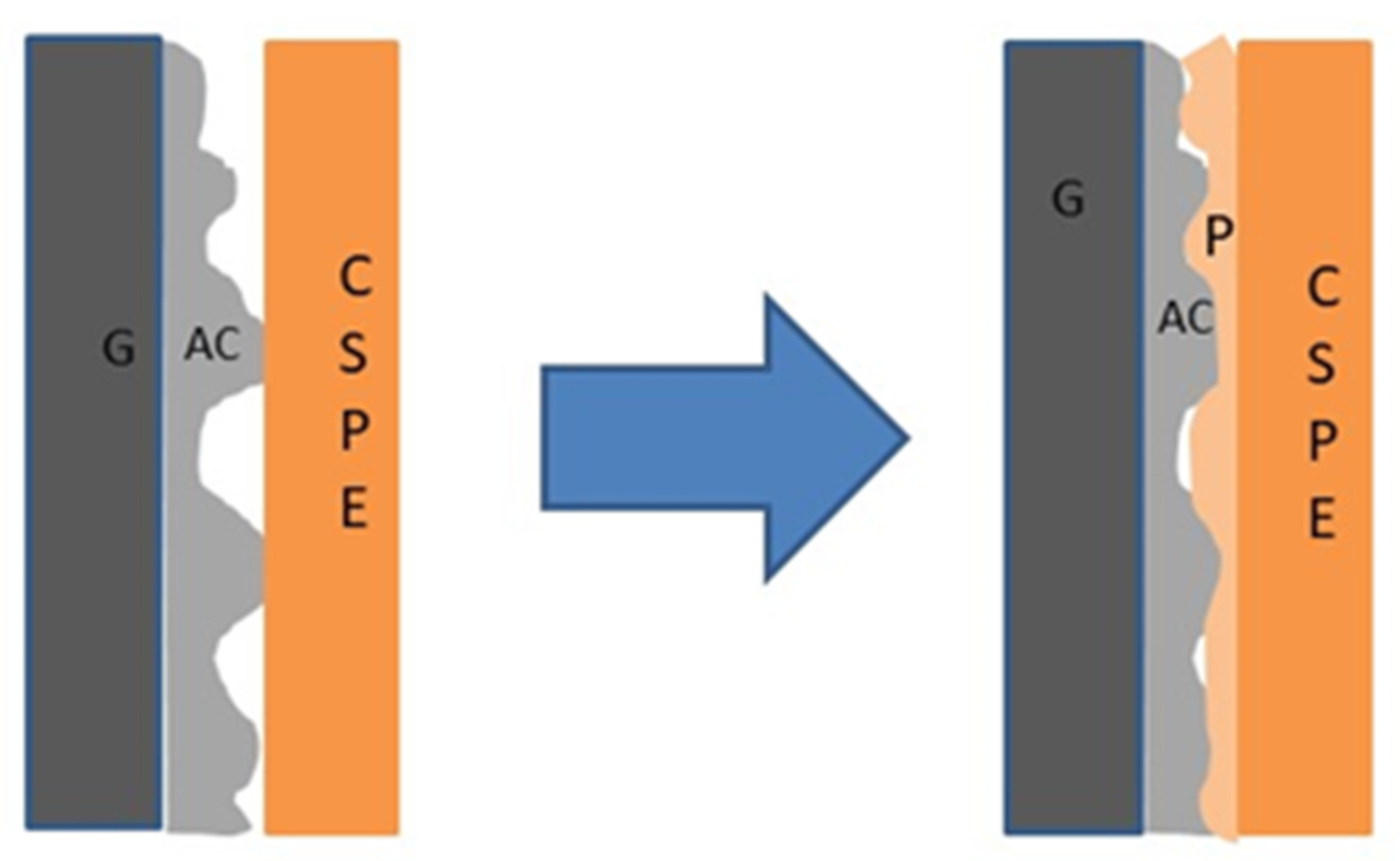
Figure 1. Illustration of the solid polymer electrolyte–electrode contact with and without polymer (P)-added electrodes. Here, G, AC, and CSPE represent the graphite current collector sheet, activated carbon, and composite solid polymer electrolyte (CSPE) membrane, respectively.
Batteries 09 00081 g001
Figure 2. (a) Photograph of the as-prepared free-standing composite solid polymer electrolyte membrane (40 LATP) used for cell fabrication (b) ASSC fabricated using a polymer-added electrode. FESEM images of the (c) electrolyte membrane, (d) Activated carbon electrode without polymer (ACE), and (e) Activated carbon electrode with polymer (P-ACE).
Batteries 09 00081 g002
Figure 3. (a) Nyquist plots of ASSCs consisting of different electrode compositions, P-ACE and ACE with a 40LATP membrane. Inset plot on an extended scale (b) Real (C′) and imaginary (C″) part of the capacitance as a function of frequency for the ASSC with the P-ACE electrodes. Inset of (b) shows relaxation in the cell with the ACE electrodes. (c) Cyclic voltammograms recorded at 100 mV s−1 for the ASSCs with the P-ACE and ACE electrodes. Current was normalized to activated carbon amount on a single electrode for a comparison.
Batteries 09 00081 g003aBatteries 09 00081 g003b
Figure 4. GCD cycles (a) for different electrode compositions, (b) for cells with P-ACE at 1.5 Ag−1, 2 V, (c) for cells with ACEs at different current densities ranging from 0.9 mA (1.34 Ag−1) to 10 mA (14.92 Ag−1). (d) The Cs variation with discharge current. Inset of (d) shows the coulombic efficiency versus current density. (e) ESR versus discharge currents. (f) GCD scans for cells and ACEs with coulombic efficiency vs cycle number in the inset. (g) GCD scans for cells with P-ACEs, coulombic efficiency vs cycle number in the inset. (h) Specific capacitance as a function of the cycle number for cells with ACE and P-ACE electrodes.
Batteries 09 00081 g004aBatteries 09 00081 g004b
Table 1. Typical parameters of ASSCs with various electrode compositions, viz., specific capacitance (Cs), specific energy (E), and specific power (P), along with ESR and coulombic efficiency (ɛ).
CSPE
MEMBRANE
COMPOSITON
Cs
(Fg−1)
E
(Wh kg−1)
P
(W kg−1)
ESR
(Ω cm2)
ɛ (%)
65AC:8SA:7AB:20P
(65 P-ACE)
96.3012.3689059.2396
65AC:17.5SA:17.5AB
(65ACE)
71.939.06881114.0193
75AC:8SA:7AB:10P
(75 P-ACE)
99.3312.1475480.8986
75AC:12.5SA:12.5AB
(75ACE)
97.4811.92740108.1380
80AC:8SA:7AB:5P
(80 P-ACE)
100.2312.3871840.1295
80AC:10SA:10AB
(80 ACE)
68.4810.35697.60102.8594
Table 2. Strategies adopted by various research groups to tailor electrode properties and interfaces.
Electrode Material Strategy Adopted Electrolyte CompositionImportant Outcomes
Carbon [44]Plasma treatment1 M H2SO4Surface functionality, improved cycling
Graphene CNT composite [45]Modification using PANI nano-cones 1 M KCl, EMI-TFSIImproved specific capacitance, energy and power density
Reduced Graphene oxide [46]ZnO-template assisted alkaline treatment1 M H2SO4Interconnected porous structure, high energy density and power density
Activated carbon [47]Tailoring the interface by applying pressure KOH, NaOH, LiCl etc.Two orders of magnitude rise in capacitance
PIL-RGO [48]Incorporation of polymer ionic liquidEMIM NTF2Enhancement in power density, energy density, and specific capacitance
Activated carbon [8]Natural cellulose as a binder1 M Et4NBF4, PYR14TFSI, Na2SO4Improved thermal and cycling stability
Carbon Cloth [10]Incorporation of graphene quantum dots 1 M H2SO4, PVA/H2SO4 Enhanced flexibility and electrochemical stability window
Carbon Fiber Paper [49]Deposition of polymerized poly(3,4-ethylenedioxythiophene) (PEDOT) over carbon fiber paper0.01 M of EDOT and 0.1 M LiClO4 in acetonitrile, gel polymer electrolyteGood capacitive performance and specific energy. Improved electrochemical performance
Mesoporous carbon [50]Hollow ordered mesoporous carbon materials by self-assembling Resol F12 micelles on MOF nanoplate 6 M KOHImproved capacitive properties and shortened diffusion pathways provide smooth channels to facilitate ion transport
Carbon [11]Coating dielectric film using atomic layer deposition technique1 M MeEt3NBF4/AN organic electrolyte83% capacity retention at 0.5 Ag−1 at 3.5 V after 20,000 cycles, high energy density
Activated carbon [13] Heterostructure FeS2/TiO2NaClO4 ester-based solution Improved cycling stability, rate capability, and reduction in diffusion energy barrier, leading to rapid Na+ transport
Activated carbon [51]VS4-CNTEther based electrolyteStrong interfacial coupling leading to conducting solid electrolyte film at the interface, leading to elevated electrochemical performance
Graphene [12]Addition of polypyrrole (PPy)PVA/H3PO4 gelHigh flexibility, stretchability, and excellent electrochemical performance.
Activated Carbon (present work)Addition of polymer in the electrode 40 LATP (CSPE)Improved specific capacitance and cycling, specific energy, and power density reduction in ESR.
Disclaimer/Publisher’s Note: The statements, opinions and data contained in all publications are solely those of the individual author(s) and contributor(s) and not of MDPI and/or the editor(s). MDPI and/or the editor(s) disclaim responsibility for any injury to people or property resulting from any ideas, methods, instructions or products referred to in the content.