

Dual-Salts Electrolyte with Fluoroethylene Carbonate Additive for High-Voltage Li-Metal Batteries
by
 and
and
Zhizhen Qin
1,2,
Baolin Wu
1,2,
Dmitri L. Danilov
1,3,*,
Rüdiger-A. Eichel
1,2 and
and
Peter H. L. Notten
1,3,4,* 1
Forschungszentrum Jülich (IEK-9), D-52425 Jülich, Germany
2
Department of Chemistry, RWTH Aachen University, D-52074 Aachen, Germany
3
Department of Electrical Engineering, Eindhoven University of Technology, P.O. Box 513, 5600 MB Eindhoven, The Netherlands
4
Centre for Clean Energy Technology, University of Technology Sydney, Broadway, Sydney, NSW 2007, Australia
*
Authors to whom correspondence should be addressed.
Batteries 2023, 9(9), 477; https://doi.org/10.3390/batteries9090477
Submission received: 26 July 2023
/
Revised: 1 September 2023
/
Accepted: 20 September 2023
/
Published: 21 September 2023
(This article belongs to the Special Issue Novel Electrolytes for Batteries and Supercapacitors)
Abstract
:The combination of Li-metal anode and high-voltage cathode is regarded as a solution for the next-generation high-energy-density secondary batteries. However, a traditional electrolyte is either incompatible with the Li-metal anode or vulnerable to high voltage. This work reports a 1 M dual-salts Localized-High-Concentration-Electrolyte with Fluoroethylene carbonate (FEC) additive. It enables stable cycling of Li||LiNi0.8Co0.1Mn0.1O2 (NMC811) battery, which shows 81.5% capacity retention after 300 cycles with a charge/discharge current density of 1 C and a voltage range of 2.7–4.4 V. Scanning electron microscopy (SEM) images show that this electrolyte not only largely reduced Li dendrites and ‘dead’ Li on anode surface but also well protected the microstructure of NMC811 cathode. Possible components of both solid-electrolyte interlayer (SEI) and cathode-electrolyte interlayer (CEI) were characterized by energy-dispersive X-ray spectroscopy (EDX). The result illustrates that FEC protected Li salts from decomposition on the anode side and suppressed the decomposition of solvents on the cathode side.
1. Introduction
Lithium-ion batteries (LIBs) have been the energy boosters of developing electric vehicles, portable devices, and many other appliances in the past few decades. However, LIBs are approaching their theoretical limits in energy density (≈350 Wh·kg−1), which cannot satisfy the increasing need for rapid development of modern society [1,2,3]. Therefore, next-generation batteries with high-power, high-energy-density, and fast-charging capabilities are urgently needed [4].
Lithium metal seems to be the ultimate choice for anode material because of its ultrahigh theoretical specific capacity (3860 mAh·g−1) and low electrochemical potential (−3.04 V versus standard hydrogen electrode) [5,6]. On the other side, Ni-rich LiNixMnyCo1−x−yO2 (NMC) materials are the most promising cathodes because of their high specific capacities, low costs, and low Co contents [7,8,9,10]. For example, LiNi0.6Mn0.2Co0.2O2 (NMC622) exhibits a specific capacity over 185 mAh·g−1 and that for NMC811 even exceeds 200 mAh·g−1 [11]. Therefore, combining Li and NMC is a good choice for the next-generation battery. However, there are many challenges for this system. On the anode side, unwanted reactions between electrolyte and Li metal cause electrolyte decomposition and Li consumption, resulting in low Coulombic efficiency (CE) and fast capacity loss. Non-uniform deposition of Li leads to Li dendrites and dead Li, eventually leading to battery failures and even disasters [12]. On the cathode side, because of the cathode-electrolyte side reactions and high cutoff voltage, NMC cathodes will go through unfavorable structure changes, such as bulk and surface phase transformation [13], transition metal dissolution [14,15], and cracking of secondary particles [16]. Such degradations become more serious with increased Ni content, especially for NMC811 of commercial interest [17]. There are some strategies to overcome these challenges, for example, an artificial interlayer between electrode and electrolyte [18], solid-state electrolyte [19], porous current collector [20], and liquid electrolyte engineering [21]. Among these strategies, liquid electrolyte engineering is very efficient and fits best with the existing industry.
Traditional commercial carbonate electrolyte is incompatible with Li anode because of the latter’s extremely high reactivity [22]. Ether-based electrolytes are stable with Li metal. However, they are unstable with high voltage (>4.0 V) cathodes [23]. It has been found that high-concentration-electrolyte (HCE) can be compatible with both Li-metal and high-voltage cathode [24]. Ren et al. demonstrated that highly concentrated Lithium bis(fluorosulfonyl)imide (LiFSI) in DME can enable Li||LiNi1/3Mn1/3Co1/3O2 (NMC111) battery cycling more than 500 cycles under 4.3 V with 90% capacity retention [25]. Fan et al. demonstrated that 10 M LiFSI in carbonate electrolyte used for Li||NMC622 could bear an ultrahigh cutoff voltage of 4.6 V and showed 86% capacity retention after 100 cycles [26]. Jiao et al. reported a dual-salts HCE composed of 2 M Lithium bis(trifluoromethanesulfonyl)imide (LiTFSI) and 2 M Lithium difluoro(oxalato)borate (LiDFOB) in 1,2-Dimethoxyethane (DME). It was used for Li||NMC111 battery for cycling with a cutoff voltage of 4.3 V and showed excellent cycling performance with 80% capacity retention over 500 cycles [27]. However, the high cost, high viscosity, and poor wettability make HCEs impractical. In order to overcome these disadvantages, researchers used cosolvents to dilute HCEs which produce a series of Localized-High-Concentration-Electrolytes (LHCEs). These cosolvents are normally Fluorinated-ethers which are miscible with organic solvents but will not coordinate with Li salts [28], for example, Bis(2,2,2-trifluoroethyl) ether (BTFE) [29], 1,1,2,2-Tetrafluoroethyl-2,2,3,3-Tetrafluoropropyl ether (TTE) [30], and Tris(2,2,2-trifluoroethyl)orthoformate (TFEO) [31]. Yu et al. reported an electrolyte: 1.2 M LiFSI in carbonate solvent with BTFE as diluent and 0.15 M LiDFOB as additives [32]. This electrolyte enabled dendrites-free Li deposition with a high CE of 98.5% for Li||NMC111 battery. Ren et al. used LiFSI in DME with TTE as cosolvent (1: 1.2: 3 in molar ratio) for Li||NMC811 cell under 2.8–4.4 V. This cell retained over 80% capacity in 150 stable cycles even though very thin Li anode (50 µm) and lean electrolyte (14 µL) were used [33].
Most of the above-mentioned LHCEs still have concentrations larger than 1 M. To further explore the practical use of LHCE in high-current-density and high-voltage Li-metal batteries (LMBs), this paper reports a 1 M LiTFSI-LiDFOB (1:3 in molar ratio) dual-salts electrolyte with DME as the solvent and TTE as the cosolvent named as T1D3. With T1D3, Li||NMC811 battery shows improved cycling performance than that with commercial electrolyte. By further adding 5.5 wt% FEC, the electrolyte named T1D3-5.5 gives an even better performance in long-term cycling under high current density and high cutoff voltages of 4.4 and 4.5 V. The electrode/electrolyte interfaces are analyzed for more information about SEI and CEI.
2. Materials and Methods
2.1. Materials
A commercial cathode sheet was bought from NEI Corporation, consisting of 90% NMC811, 5% Polyvinylidene difluoride (PVDF), and 5% Carbon Black coated on Al foil. The areal capacity was ~2.0 mAh·cm−2. The NMC sheet was firstly cut into discs with diameters of 12 mm and then dried overnight before use. Li foil (>99.9%) with a thickness of 0.75 mm purchased from Sigma-Aldrich was cut into 14 mm diameter discs. Battery-grade chemicals were purchased from Sigma-Aldrich as well and used as received, including a commercial electrolyte: 1 M Lithium hexafluorophosphate (LiPF6) in Ethylene carbonate (EC), Dimethyl carbonate (DMC), Diethyl carbonate (DEC) (1:1:1 in volume ratio), LiTFSI, LiDFOB, DME, TTE, and FEC. These chemicals were kept and handled in a glovebox with water and oxygen contents less than 1 ppm. T1D3 has the composition: 0.25 M LiTFSI + 0.75 M LiDFOB in DME:TTE (1:3 in volume ratio). T1D3-5.5 was obtained by adding 5.5 wt% FEC into T1D3. The selection of a suitable salt ratio is illustrated in Supplementary Information (SI).
2.2. Electrochemical Measurements
All electrochemical measurements were conducted in an MKF120 climate chamber (Binder, Germany) under 25 °C using a VMP3 potentiostat (Biologic Seyssinet-Pariset, France). Li||NMC811 coin cell (with form factor CR2032) was constructed using an NMC811 disc as a cathode, a Li metal disc as an anode, two pieces of monolayer polypropylene (PP) separators (Celgard, Charlotte, North Carolina, USA), and the prepared electrolyte (75 μL in each battery). Galvanostatic charge/discharge cycling of Li||NMC811 cell was performed in the voltage range of 2.7–4.4 V and 2.7–4.5 V versus Li/Li+. The batteries were first cycled at C/10 for two cycles and then at 1 C for subsequent cycling (1 C = 2.0 mA·cm−2). C-rate tests of Li||NMC811 cells were conducted sequentially under 0.1 C, 0.2 C, 0.5 C 1 C, 2 C, and 0.1 C. Cyclic voltammogram (CV) tests were operated in a voltage window of 2.7–4.4 V at a scan rate of 0.05 mV·s−1. Electrochemical impedance spectroscopy (EIS) tests were conducted at 4.0 V with an amplitude of 10 mV in the frequency range of 20 kHz−10 mHz. Li||Li cell was constructed using two Li discs as electrodes. Other parts are the same as in Li||NMC811 cell. It was tested at a high current density of 2.5 mA·cm−2 to a plating/striping capacity of 1 mAh·cm−2.
2.3. Material Characterization
Scanning electron microscopy (SEM) and energy-dispersive X-ray spectroscopy (EDX) experiments were conducted using a Quanta FEG 650 (FEI) environmental scanning electron microscope matched with EDAX APEX. All the tests were performed at a voltage of 30 kV.
3. Results and Discussion
3.1. Electrochemical Performance
Figure 1a shows the cycling stability of Li||NMC811 cells under 2.7–4.4 V with commercial electrolyte T1D3 and T1D3-5.5, respectively. The initial capacity of the cell with commercial electrolyte at 1 C is 171.4 mAh·g−1. It suffers from rapid capacity loss after around 75 cycles and only retains 51.5% of its initial capacity after 100 cycles. It also has the lowest average CE among these three electrolytes, 98.2%, excluding the first three cycles. The poor performance is due to the incompatibility of carbonate with LMBs, as mentioned above. Although the cell with T1D3 shows a lower initial capacity in the first cycle under 1 C, which is 169.5 mAh·g−1, the capacity slowly increases to 186.6 mAh·g−1 after 55 cycles. A similar phenomenon was observed in graphite||LiFePO4 batteries under high current density [34]. Matthieu et al. attributed this phenomenon to the so-called ‘electrochemical milling’ [35]. During electrochemical milling, moderately cracked cathode particles provided a larger active surface area and decreased charge transfer resistance (Rct). The SEM image of the NMC811 surface and the Rct changes, both will be discussed later, are consistent with this hypothesis. Although the average CE increases to 99.5% after the first three cycles, after around 65 cycles, the capacity starts to decrease rapidly. This phenomenon is probably related to the Li-dendrites formation, Li-salt consumption, and structural degradation of NMC811, which will be discussed in more detail later. T1D3-5.5 shows the best performance among these three electrolytes. Starting with an initial capacity of 187.2 mAh·g−1, it shows a moderate capacity increasing to 191 mAh·g−1 after 13 cycles. After 300 cycles, it still has 81.5% of the initial capacity, and no fast capacity loss happened. The average CE further increased to 99.7%. This outstanding performance improvement could be attributed to the synergy of FEC with Li salts. Figure 1b–d shows the associated galvanostatic profiles of Li||NMC811 cells with three different electrolytes. Cell with commercial electrolyte shows large polarization increasing until early failure. Cell with T1D3 also shows rapid polarization after 50 cycles, while with T1D3-5.5, the polarization process is relatively slow throughout the cycling.
CV curves of Li||NMC811 cells in three electrolytes are shown in Figure 2a–c. With commercial electrolyte, Figure 2a shows typical CV curves of NMC material. Oxidation peaks around 3.8 V correspond to the phase transition process from hexagonal-1 (H1) to monoclinic (M). Oxidation peaks around 4.0 V correspond to the transition from M to hexagonal-2 (H2). Then H2 transfers to hexagonal-3 (H3) at around 4.2 V [36,37]. Corresponding reduction peaks during the reverse process are also labeled. In the first cycle, the peak difference between the first oxidation peak and the corresponding reduction peak is 0.28 V. CV curve of T1D3 (Figure 2b) have a similar shape to commercial electrolyte. However, in the first cycle, the peak difference between the first oxidation peak and the corresponding reduction peak is down to 0.23 V. Besides, the overlapping of subsequent CV curves of T1D3 is better, which indicates better reversibility of Li de/intercalation. However, the first oxidation peak current density of T1D3 in the first cycle is smaller than that of commercial electrolyte, which means the kinetic of T1D3 at the early stage is not so good. After adding FEC, the initial kinetic is improved, which causes higher current density. In the first cycle, a large oxidation peak centers around 4.05 V. It may come from the irreversible decomposition of FEC to form stable SEI/CEI, which improves the long-term cycling performance.
EIS of Li||NMC811 batteries with three different electrolytes were also examined. EIS curves of fresh Li||NMC811 cells show only one semicircle at high frequency, and a slope at low frequency (Figure 2d). The semicircle represents the interfacial impedance when Li-ions pass through the interface between electrolyte and fresh electrode [38]. Cells with T1D3 and T1D3-5.5 have lower impedance than commercial electrolyte, which may be attributed to their better wettability and stronger reaction activity with the NMC811 cathode. After 2 and 100 cycles, EIS curves show three semicircles. The first and second semicircles at high and middle frequencies represent the interphase impedance, mainly referring to the impedance of SEI/CEI (denoted as R1 and R2). The third semicircle at low frequency represents the charge transfer impedance (Rct) [39]. The impedance values (Table 1) were calculated by fitting the EIS curves using the equivalent circuits indicated in Figure 2e,f by Z-view software. Detailed fitting data can be seen in Table S1 in SI. The total impedance (Rtotal) of the cell with commercial electrolyte presents a large increase after 100 cycles, especially the Rct, which may be the reason for the severe specific capacity loss during cycling. By contrast, the Rtotal of T1D3 and T1D3-5.5 show only little changes. Although R1 increases and R2 decreases after 100 cycles, the sum of R1 and R2 remains almost the same. It is worth noting that the Rct of T1D3 decreases. This result is consistent with the early-stage capacity increasing caused by ‘electrochemical milling’ mentioned above.
To further demonstrate the superior performance of T1D3-5.5, some electrochemistry tests were conducted under more harsh conditions, shown in Figure 3. The C-rates test is shown in Figure 3a. Under current density of 0.1 C, Li||NMC811 gives a maximum capacity of 207.4 mAh·g−1, 218.7 mAh·g−1 and 218.9 mAh·g−1 with commercial electrolyte, T1D3 and T1D3-5.5, respectively. As the charge/discharge current density increases, the capacity decreases. When current rates are under 1 C, cells with T1D3 and T1D3-5.5 show similar discharge capacities, which are higher than that of cell with commercial electrolyte. When the current density increases to 2 C, a cell with T1D3-5.5 has a capacity of 162.2 mAh·g−1, that with commercial electrolyte is only 135.2 mAh·g−1. Although cell with T1D3 still shows 151.5 mAh·g−1 at the first cycle under 2 C, the capacity drops rapidly to 99.5 mAh·g−1 after only 5 cycles. When the current density declines to 0.1 C again, cells with T1D3 and T1D3-5.5 show almost full capacity recovery, while that with commercial electrolyte is around 96%. It can be concluded that the rate performance of Li||NMC811 with T1D3-5.5 is superior to identical cells with commercial electrolyte and T1D3.
The cycling performance of Li||NMC811 cells with a higher cutoff voltage of 4.5 V is shown in Figure 3b. Cell with commercial electrolyte gives an initial capacity of 194.5 mAh·g−1 at 1 C. It undergoes fast capacity loss after around 70 cycles and only has 51.7% capacity retention after 100 cycles with an average CE of 97.9%. Cell with T1D3 shows better performance, 201.5 mAh·g−1 in the first cycle, and 80% remains after 175 cycles with an average CE of 99.6%. However, after 179 cycles, a sudden capacity drop followed by fluctuations occurs, indicating battery failure. Cell with T1D3-5.5 still shows excellent performance. The initial capacity at 1 C is 202.4 mAh·g−1. After 200 cycles, it still retains 82.8% of its initial capacity. Besides, there is no rapid capacity loss within 300 cycles, showing an average CE of 99.73%.
Li||Li symmetrical cells with three electrolytes were tested under a high current density of 2.5 mA·cm−2. As is shown in Figure 3c, a cell with commercial electrolyte suffers from huge overpotential after 100 h. Cells with T1D3 and T1D3-5.5 show better Li plating/striping behavior, especially when T1D3-5.5 is used, showing the smallest and most stable overpotential within 200 h.
3.2. The Anode/Electrolyte Interface
The compatibility of the electrolyte with the anode is a key aspect of long-term cycling stability [40]. Thus, the morphologies of Li-metal anodes and possible SEI components after cycling in three electrolytes were characterized by SEM-EDX, shown in Figure 4.
After 100 cycles, there are full of non-uniform needle-like Li dendrites on the Li surface cycled in the commercial electrolyte (Figure 4a). These Li dendrites could cause rapid electrolyte decomposition and further Li consumption which is illustrated by the lower CE. Eventually, these dendrites could lead to battery failure. With T1D3, even though the Li surface looks denser, the isolated ‘dead Li’ and Li dendrites are still obvious (Figure 4b). These dendrites could be part of the reason why the battery suffers fast capacity loss after around 65 cycles. On the contrary, T1D3-5.5 results in the flattest and densest Li surface with almost no dendrites (Figure 4c). Therefore, the stability of the Li-metal anode and the long-term cycling performance of LMB are improved.
EDX analysis gives the relative content of different elements in SEI, as shown in Figure 4d. SEI formed in the commercial electrolyte has the highest C content and lowest F content, which implies that there are many organic species, such as Li2CO3, C=O, C–O, and –CH2–CH2–O– coming from carbonate decomposition [41], but only a small amount of LiF from LiPF6. This kind of SEI is too fragile to protect Li from aggressive solvents because it cannot bear the huge volume changes of the Li anode [42]. Besides, there may also be some LixPOyFz and LixPFy in this SEI, which is indicated by element P [43].
SEIs formed in T1D3 and T1D3-5.5 both have lower C content and higher F content compared with the commercial electrolyte. That may contribute to better cycling performance. T1D3 has the highest F, B, and S content. That means LiDFOB and LiTFSI are actively involved in the SEI formation to generate LiF, C-F, and B-F species [27]. After adding FEC, the content of B and S become lower, and O content becomes higher. That is probably because of the good film-forming function of FEC. FEC acts as a sacrifice to be decomposed first and produce desired SEI, which contains many LiF species [44]. This SEI guides the uniform Li plating/striping and gives a smooth Li surface in Figure 4c. Besides, this SEI also prevents further contact between Li salts and anode, reduces the consumption of LiDFOB and LiTFSI, thus giving the best long-term cycling performance.
3.3. The Cathode/Electrolyte Interface
The interface between the cathode and electrolyte is also essential, especially under high cutoff voltage [45]. SEM-EDX characterization was also performed to give information about the NMC811 structure and CEI component.
The SEM result of pristine NMC811 shows good microstructure. No film is formed on the particle surface shown in Figure 5a. After 100 cycles in three different electrolytes, all NMC811s show clear film formation on the surface (Figure 5b–d). However, their morphology demonstrates huge differences. NMC811 cycled in the commercial electrolyte shows severe pulverization (Figure 5b). It is probably caused by the high voltage and corrosion of HF formed by hydrolysis of LiPF6 [46]. Although there is no LiPF6 in T1D3 and T1D3-5.5, free DME in the electrolyte will be easily oxidized to generate acidic species leaching the cathode during cycling [47]. NMC811 cycled in T1D3 (Figure 5c) shows improved structure compared to the material cycled in the commercial electrolyte. However, one can still find cracked NMC811 particles which indicate that T1D3 cannot help to build robust CEI. By contrast, the particle structure of NMC811 cycled in T1D3-5.5 remained intact (Figure 5d), likely due to the CEI structure discussed below.
EDX analysis (Figure 5e) shows the possible compositions of CEIs on the surface of NMC811s cycled in three electrolytes. It is known that CEI formed in commercial electrolyte is mainly composed of inorganic LiF and organic species such as –C–O–, –C=O–, and LixPOyFz, which is consistent with the elements detected by EDX. In comparison, CEI formed in T1D3 and T1D3-5.5 show element B representing the decomposition species from LiDFOB, for example, LixBOy or LixBOyFz [48]. By comparing the relative content of the elements in T1D3 and T1D3-5.5, we can find the influence of FEC. NMC811 cycled in T1D3 has higher O content which may come from the deleterious process of DME responsible for the NMC811 cracking in Figure 5c. The low B and S content in T1D3 means LiDFOB and LiTFSI participate only marginally in the formation of CEI. Thus, the higher F content may come from the degradation of TTE. NMC811 cycled in T1D3-5.5 shows very high C content from the PEO-like polymer species due to adding FEC. These PEO-like polymer species could improve the cycling performance of the Li||NMC811 cell [49]. Meanwhile, adding FEC decreases the degradation of DME and TTE since T1D3-5.5 shows lower O and F content. The higher B content means more LiDFOB participates in forming CEI, which makes CEI more robust.
4. Conclusions and Outlook
We have developed an electrolyte composed of 0.25 M LiTFSI and 0.75 M LiDFOB with DME/TTE solvent and FEC additive for high-voltage LMBs. Li||NMC811 battery with this electrolyte, cycling under 2.7–4.4 V, gives an initial capacity of 187.2 mAh·g−1 and shows a stable long-term cycling performance with 81.5% capacity retention after 300 cycles at 1 C. Even under a higher cutoff voltage of 4.5 V, the battery shows no rapid decay within 300 cycles. These excellent results can be attributed to the stable SEI and CEI formed by electrolyte, which provided a smooth and dense Li surface and well-protected NMC microstructure. Besides, adding FEC protects not only the Li salts but also the solvents from over-consumption, which is also helpful for long-term cycling performance. However, limited by the characterization methods and the nature of SEI/CEI, a lot of work still needs to be done in the future to thoroughly study the composition and impact of SEI/CEI on the battery. This work demonstrates the promising future of electrolyte engineering in achieving the practical application of Li metal batteries. However, to meet the requirements of practical application, batteries need to be tested under more harsh conditions, for example, lean electrolyte and thin Li anode (under 50 µm). Besides, other properties of electrolytes also need to be done, for example: the effect of the ambient temperature, flame retardant performance, and other safety tests.
Supplementary Materials
The following supporting information can be downloaded at: https://www.mdpi.com/article/10.3390/batteries9090477/s1, Figure S1: Cycling performance of three electrolytes with different LiTFSI to LiDFOB ratios under 2.7–4.4 V; Figure S2: Cycling performance of T1D3-5.5 and T1D1-5.5 under 2.7–4.4 V. Table S1: All the EIS fitting data of Li||NMC811 cells in three electrolytes after 2 cycles and 100 cycles.
Author Contributions
Writing—original draft preparation, Z.Q.; writing—review and editing, B.W.; writing—review and editing, D.L.D.; writing—review and editing, P.H.L.N.; supervision, project administration, R.-A.E. All authors have read and agreed to the published version of the manuscript.
Funding
This research received no external funding.
Data Availability Statement
The data presented in this study are available on request from the corresponding author.
Acknowledgments
The author Zhizhen Qin gratefully acknowledges fellowship support from the China Scholarship Council. D.L. Danilov appreciates the support from the ProMoBiS project funded by BMBF (Germany).
Conflicts of Interest
The authors declare no conflict of interest.
References
- Liu, B.; Zhang, J.-G.; Xu, W. Advancing Lithium Metal Batteries. Joule 2018, 2, 833–845. [Google Scholar] [CrossRef]
- Zhang, H.; Qu, W.; Chen, N.; Huang, Y.; Li, L.; Wu, F.; Chen, R. Ionic liquid electrolyte with highly concentrated LiTFSI for lithium metal batteries. Electrochim. Acta 2018, 285, 78–85. [Google Scholar] [CrossRef]
- Fang, S.; Shen, L.; Li, S.; Dou, H.; Zhang, X. Self-supported TiN nanorod array/carbon textile as a lithium host that induces dendrite-free lithium plating with high rates and long cycle life. J. Mater. Chem. A 2020, 8, 3293–3299. [Google Scholar] [CrossRef]
- Li, G. Regulating Mass Transport Behavior for High-Performance Lithium Metal Batteries and Fast-Charging Lithium-Ion Batteries. Adv. Energy Mater. 2021, 11, 2002891. [Google Scholar] [CrossRef]
- Tarascon, J.-M.; Armand, M. Issues and challenges facing rechargeable lithium batteries. Nature 2001, 414, 359–367. [Google Scholar] [CrossRef]
- Cheng, X.; Zhang, R.; Zhao, C.Z.; Zhang, Q. Toward Safe Lithium Metal Anode in Rechargeable Batteries: A Review. Chem. Rev. 2017, 117, 10403–10473. [Google Scholar] [CrossRef]
- Liu, J.; Bao, Z.; Dufek, E.J.; Goodenough, J.B.; Khalifah, P.; Li, Q.; Liaw, B.Y.; Liu, P.; Manthiram, A.; Meng, Y.S.; et al. Pathways for practical high-energy long-cycling lithium metal batteries. Nat. Energy 2019, 4, 180–186. [Google Scholar] [CrossRef]
- Lu, J.; Xu, X.; Fan, W.; Xin, Y.; Wang, W.; Fan, C.; Chen, P.; Zhao, J.; Liu, J.; Hou, Y. Phenyl 4-Fluorobenzene Sulfonate as a Versatile Film-Forming Electrolyte Additive for Wide-Temperature-Range NCM811//Graphite Batteries. ACS Appl. Energy Mater. 2022, 5, 6324–6334. [Google Scholar] [CrossRef]
- Wu, B.; Chen, C.; Danilov, D.L.; Eichel, R.-A.; Notten, P.H.L. All-Solid-State Thin Film Li-Ion Batteries: New Challenges, New Materials, and New Designs. Batteries 2023, 9, 186. [Google Scholar] [CrossRef]
- Dong, X.; Yao, J.; Zhu, W.; Huang, X.; Kuai, X.; Tang, J.; Li, X.; Dai, S.; Shen, L.; Yang, R.; et al. Enhanced high-voltage cycling stability of Ni-rich cathode materials via the self-assembly of Mn-rich shells. J. Mater. Chem. A 2019, 7, 20262–20273. [Google Scholar] [CrossRef]
- Pham, T.D.; Bin, F.A.; Kim, J.; Oh, H.M.; Lee, K.K. Practical High-Voltage Lithium Metal Batteries Enabled by Tuning the Solvation Structure in Weakly Solvating Electrolyte. Small 2022, 18, e2107492. [Google Scholar] [CrossRef] [PubMed]
- Xie, Z.; An, X.; Wu, Z.; Yue, X.; Wang, J.; Hao, X.; Abudula, A.; Guan, G. Fluoropyridine family: Bifunction as electrolyte solvent and additive to achieve dendrites-free lithium metal batteries. J. Mater. Sci. Technol. 2021, 74, 119–127. [Google Scholar] [CrossRef]
- Ryu, H.-H.; Park, K.-J.; Yoon, C.; Sun, Y.-K. Capacity Fading of Ni-Rich Li[NixCoyMn1−x−y]O2 (0.6 ≤ x ≤ 0.95) Cathodes for High-Energy-Density Lithium-Ion Batteries: Bulk or Surface Degradation? Chem. Mater. 2018, 30, 1155–1163. [Google Scholar] [CrossRef]
- Li, W.; Kim, U.H.; Dolocan, A.; Sun, Y.K.; Manthiram, A. Formation and Inhibition of Metallic Lithium Microstructures in Lithium Batteries Driven by Chemical Crossover. ACS Nano 2017, 11, 5853–5863. [Google Scholar] [CrossRef] [PubMed]
- Jiang, M.; Danilov, D.L.; Eichel, R.-A.; Notten, P.H.L. A Review of Degradation Mechanisms and Recent Achievements for Ni-Rich Cathode-Based Li-Ion Batteries. Adv. Energy Mater. 2021, 11, 2103005. [Google Scholar] [CrossRef]
- Xu, G.-L.; Liu, Q.; Lau, K.K.S.; Liu, Y.; Liu, X.; Gao, H.; Zhou, X.; Zhang, M.; Ren, Y.; Li, J.; et al. Building ultraconformal protective layers on both secondary and primary particles of layered lithium transition metal oxide cathodes. Nat. Energy 2019, 4, 484–494. [Google Scholar] [CrossRef]
- Xue, W.; Huang, M.; Li, Y.; Zhu, Y.G.; Gao, R.; Xiao, X.; Zhang, W.; Li, S.; Xu, G.; Yu, Y.; et al. Ultra-high-voltage Ni-rich layered cathodes in practical Li metal batteries enabled by a sulfonamide-based electrolyte. Nat. Energy 2021, 6, 495–505. [Google Scholar] [CrossRef]
- Tikekar, M.; Choudhury, S.; Tu, Z.; Archer, L. Design principles for electrolytes and interfaces for stable lithium-metal batteries. Nat. Energy 2016, 1, 16114. [Google Scholar] [CrossRef]
- Chen, C.; Jiang, M.; Zhou, T.; Raijmakers, L.; Vezhlev, E.; Wu, B.; Schülli, T.U.; Danilov, D.L.; Wei, Y.; Eichel, R.-A.; et al. Interface Aspects in All-Solid-State Li-Based Batteries Reviewed. Adv. Energy Mater. 2021, 11, 2003939. [Google Scholar] [CrossRef]
- Zhang, C.; Lyu, R.; Lv, W.; Li, H.; Jiang, W.; Li, J.; Gu, S.; Zhou, G.; Huang, Z.; Zhang, Y.; et al. A Lightweight 3D Cu Nanowire Network with Phosphidation Gradient as Current Collector for High-Density Nucleation and Stable Deposition of Lithium. Adv. Mater. 2019, 31, 1904991. [Google Scholar] [CrossRef]
- Qin, K.; Holguin, K.; Mohammadiroudbari, M.; Huang, J.; Kim, E.Y.S.; Hall, R.; Luo, C. Strategies in Structure and Electrolyte Design for High-Performance Lithium Metal Batteries. Adv. Funct. Mater. 2021, 31, 2009694. [Google Scholar] [CrossRef]
- Piao, Z.; Gao, R.; Liu, Y.; Zhou, G.; Cheng, H.-M. A Review on Regulating Li Solvation Structures in Carbonate Electrolytes for Lithium. Adv. Mater. 2022, 35, 2206009. [Google Scholar]
- Zhang, J.; Zhang, H.; Deng, L.; Yang, Y. An additive-enabled ether-based electrolyte to realize stable cycling of high-voltage anode-free lithium metal batteries. Energy Storage Mater. 2023, 54, 450–460. [Google Scholar] [CrossRef]
- Jiang, G.; Li, F.; Wang, H.; Wu, M.; Qi, S.; Liu, X.; Yang, S.; Ma, J. Perspective on High-Concentration Electrolytes for Lithium Metal Batteries. Small Struct. 2021, 2, 2000122. [Google Scholar] [CrossRef]
- Ren, X.; Zou, L.; Jiao, S.; Mei, D.; Engelhard, M.H.; Li, Q.; Lee, H.; Niu, C.; Adams, B.D.; Wang, C.; et al. High-Concentration Ether Electrolytes for Stable High-Voltage Lithium Metal Batteries. ACS Energy Lett. 2019, 4, 896–902. [Google Scholar] [CrossRef]
- Fan, X.; Chen, L.; Ji, X.; Deng, T.; Hou, S.; Chen, J.; Zheng, J.; Wang, F.; Jiang, J.; Xu, K.; et al. Highly Fluorinated Interphases Enable High-Voltage Li-Metal Batteries. Chem 2018, 4, 174–185. [Google Scholar] [CrossRef]
- Jiao, S.; Ren, X.; Cao, R.; Engelhard, M.H.; Liu, Y.; Hu, D.; Mei, D.; Zheng, J.; Zhao, W.; Li, Q.; et al. Stable cycling of high-voltage lithium metal batteries in ether electrolytes. Nat. Energy 2018, 3, 739–746. [Google Scholar] [CrossRef]
- Zheng, Y.; Soto, F.A.; Ponce, V.; Seminario, J.M.; Cao, X.; Zhang, J.-G.; Balbuena, P.B. Localized high concentration electrolyte behavior near a lithium–metal anode surface. J. Mater. Chem. A 2019, 7, 25047–25055. [Google Scholar] [CrossRef]
- Chen, S.; Zheng, J.; Yu, L.; Ren, X.; Engelhard, M.H.; Niu, C.; Lee, H.; Xu, W.; Xiao, J.; Liu, J.; et al. High-Efficiency Lithium Metal Batteries with Fire-Retardant Electrolytes. Joule 2018, 2, 1548–1558. [Google Scholar] [CrossRef]
- Fu, J.; Ji, X.; Chen, J.; Chen, L.; Fan, X.; Mu, D.; Wang, C. Lithium Nitrate Regulated Sulfone Electrolytes for Lithium Metal Batteries. Angew. Chem. Int. Ed. 2020, 59, 22194–22201. [Google Scholar] [CrossRef]
- Cao, X.; Ren, X.; Zou, L.; Engelhard, M.H.; Huang, W.; Wang, H.; Matthews, B.E.; Lee, H.; Niu, C.; Arey, B.W.; et al. Monolithic solid–electrolyte interphases formed in fluorinated orthoformate-based electrolytes minimize Li depletion and pulverization. Nat. Energy 2019, 4, 796–805. [Google Scholar] [CrossRef]
- Yu, L.; Cheng, S.; Lee, H.; Zhang, L.; Engelhard, M.H.; Li, Q.; Jiao, S.; Liu, J.; Xu, W.; Zhang, J.-G. A Localized High-Concentration Electrolyte with Optimized Solvents and Lithium Difluoro(oxalate)borate Additive for Stable Lithium Metal Batteries. ACS Energy Lett. 2018, 3, 2059–2067. [Google Scholar] [CrossRef]
- Ren, X.; Zhou, L.; Cao, X.; Engelhard, M.H.; Liu, W.; Burton, S.D.; Lee, H.; Niu, C.; Matthews, B.E.; Zhu, Z.; et al. Enabling High-Voltage Lithium-Metal Batteries under Practical Conditions. Joule 2019, 3, 1662–1676. [Google Scholar] [CrossRef]
- Huang, H.; Yin, S.-C.; Nazar, L. Approaching theoretical capacity of LiFePO4 at room temperature at high rates. Electrochem. Solid-State Lett. 2001, 4, A170–A172. [Google Scholar] [CrossRef]
- Dubarry, M.; Truchot, C.; Liaw, B. Cell degradation in commercial LiFePO4 cells with high-power and high-energy designs. J. Power Sources 2014, 258, 408–419. [Google Scholar] [CrossRef]
- Alqahtani, Y.M.; Williams, Q.L. Reduction of Capacity Fading in High-Voltage NMC Batteries with the Addition of Reduced Graphene Oxide. Materials 2022, 15, 2146. [Google Scholar] [CrossRef]
- Tran, M.X.; Smyrek, P.; Park, J.; Pfleging, W.; Lee, J.K. Ultrafast-Laser Micro-Structuring of LiNi0.8Mn0.1Co0.1O2 Cathode for High-Rate Capability of Three-Dimensional Li-ion Batteries. Nanomaterials 2022, 12, 3897. [Google Scholar] [CrossRef]
- Shen, C.-H.; Wang, Q.; Chen, H.-J.; Shi, C.-G.; Zhang, H.-Y.; Huang, L.; Li, J.-T.; Sun, S.-G. In Situ Multitechnical Investigation into Capacity Fading of High-Voltage LiNi0.5Co0.2Mn0.3O2. ACS Appl. Mater. Interfaces 2016, 8, 35323–35335. [Google Scholar] [CrossRef]
- Mao, M.; Huang, B.; Li, Q.; Wnag, C.; He, Y.-B.; Knag, F. In-situ construction of hierarchical cathode electrolyte interphase for high performance LiNi0.8Co0.1Mn0.1O2/Li metal battery. Nano Energy 2020, 78, 105282. [Google Scholar] [CrossRef]
- Zhang, J.-G.; Xu, W.; Xiao, J.; Cao, X.; Liu, J. Lithium Metal Anodes with Nonaqueous Electrolytes. Chem. Rev. 2020, 120, 13312–13348. [Google Scholar] [CrossRef]
- Ding, F.; Xu, W.; Chen, X.; Zhang, J.; Engelhard, M.H.; Zhang, Y.; Johnsin, B.R.; Crum, J.V.; Blake, T.A.; Liu, X.; et al. Effects of Carbonate Solvents and Lithium Salts on Morphology and Coulombic Efficiency of Lithium Electrode. J. Electrochem. Soc. 2013, 160, A1894–A1901. [Google Scholar] [CrossRef]
- Geng, Z.; Lu, J.; Li, Q.; Qiu, J.; Wang, Y.; Peng, J.; Huang, J.; Li, W.; Yu, X.; Li, H. Lithium metal batteries capable of stable operation at elevated temperature. Energy Storage Mater. 2019, 23, 646–652. [Google Scholar] [CrossRef]
- Markevich, E.; Fridman, K.; Sharabi, R.; Elazari, R.; Salitra, G.; Gottlieb, H.E.; Gershinsky, G.; Garsuch, A.; Semrau, G.; Schmidt, M.A.; et al. Amorphous Columnar Silicon Anodes for Advanced High Voltage Lithium Ion Full Cells: Dominant Factors Governing Cycling Performance. J. Electrochem. Soc. 2013, 160, A1824–A1833. [Google Scholar] [CrossRef]
- Hou, T.; Ynag, G.; Rajput, N.N.; Self, J.; Park, S.-W.; Nanda, J.; Persson, K.A. The influence of FEC on the solvation structure and reduction reaction of LiPF6/EC electrolytes and its implication for solid electrolyte interphase formation. Nano Energy 2019, 64, 103881. [Google Scholar] [CrossRef]
- Zhang, J.-N.; Li, Q.; Wang, Y.; Zhang, J.; Yu, X.; Li, H. Dynamic evolution of cathode electrolyte interphase (CEI) on high voltage LiCoO2 cathode and its interaction with Li anode. Energy Storage Mater. 2018, 14, 1–7. [Google Scholar] [CrossRef]
- Park, M.; Park, S.; Choi, N. Unanticipated Mechanism of the Trimethylsilyl Motif in Electrolyte Additives on Nickel-Rich Cathodes in Lithium-Ion Batteries. ACS Appl. Mater. Interfaces 2020, 12, 43694–43704. [Google Scholar] [CrossRef]
- Yang, J.; Li, X.; Qu, K.; Wang, Y.; Shen, K.; Jiang, C.; Yu, B.; Luo, P.; Li, Z.; Chen, M.; et al. Concentrated ternary ether electrolyte allows for stable cycling of a lithium metal battery with commercial mass loading high-nickel NMC and thin anodes. Carbon Energy 2022, 5, e275. [Google Scholar] [CrossRef]
- Hwang, J.-Y.; Park, S.-J.; Yoon, C.S.; Sun, Y.-K. Customizing a Li–metal battery that survives practical operating conditions for electric vehicle applications. Energy Environ. Sci. 2019, 12, 2174–2184. [Google Scholar] [CrossRef]
- Markevich, E.; Salitra, G.; Aurbach, D. Fluoroethylene Carbonate as an Important Component for the Formation of an Effective Solid Electrolyte Interphase on Anodes and Cathodes for Advanced Li-Ion Batteries. ACS Energy Lett. 2017, 2, 1337–1345. [Google Scholar] [CrossRef]
Figure 1.
(a) Cycling performance of Li||NMC811 cells with three electrolytes under 2.7–4.4 V. (b–d) Galvanostatic profiles of Li||NMC811 with (b) commercial electrolyte, (c) T1D3 and (d) T1D3-5.5, respectively.
Figure 1.
(a) Cycling performance of Li||NMC811 cells with three electrolytes under 2.7–4.4 V. (b–d) Galvanostatic profiles of Li||NMC811 with (b) commercial electrolyte, (c) T1D3 and (d) T1D3-5.5, respectively.

Figure 2.
(a–c) Initial three CV cycles of Li||NMC811 batteries with (a) commercial electrolyte, (b) T1D3, (c) T1D3-5.5, at 0.05 mV·s−1 under 2.7–4.4 V. (d–f) EIS curves of Li||NMC811 batteries with three electrolytes (d) before cycling, (e) after 2 cycles, and (f) after 100 cycles, respectively, at 4.0 V.
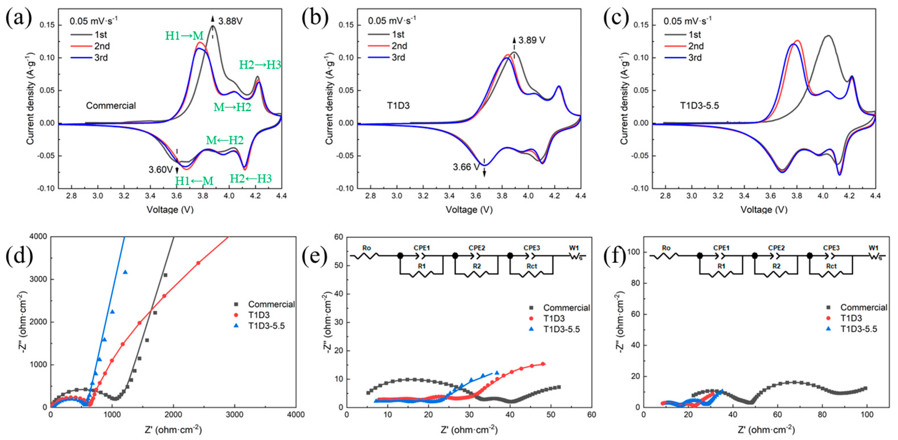
Figure 3.
(a) C-rate performance of Li||NMC811 cells with three electrolytes under 2.7–4.4 V. (b) Cycling performance of Li||NMC811 with three electrolytes under 2.7–4.5 V. (c) Cycling performance of Li||Li symmetrical cell with three electrolytes, tested at 2.5 mA·cm−2 and a capacity of 1 mAh·cm−2 per cycle.
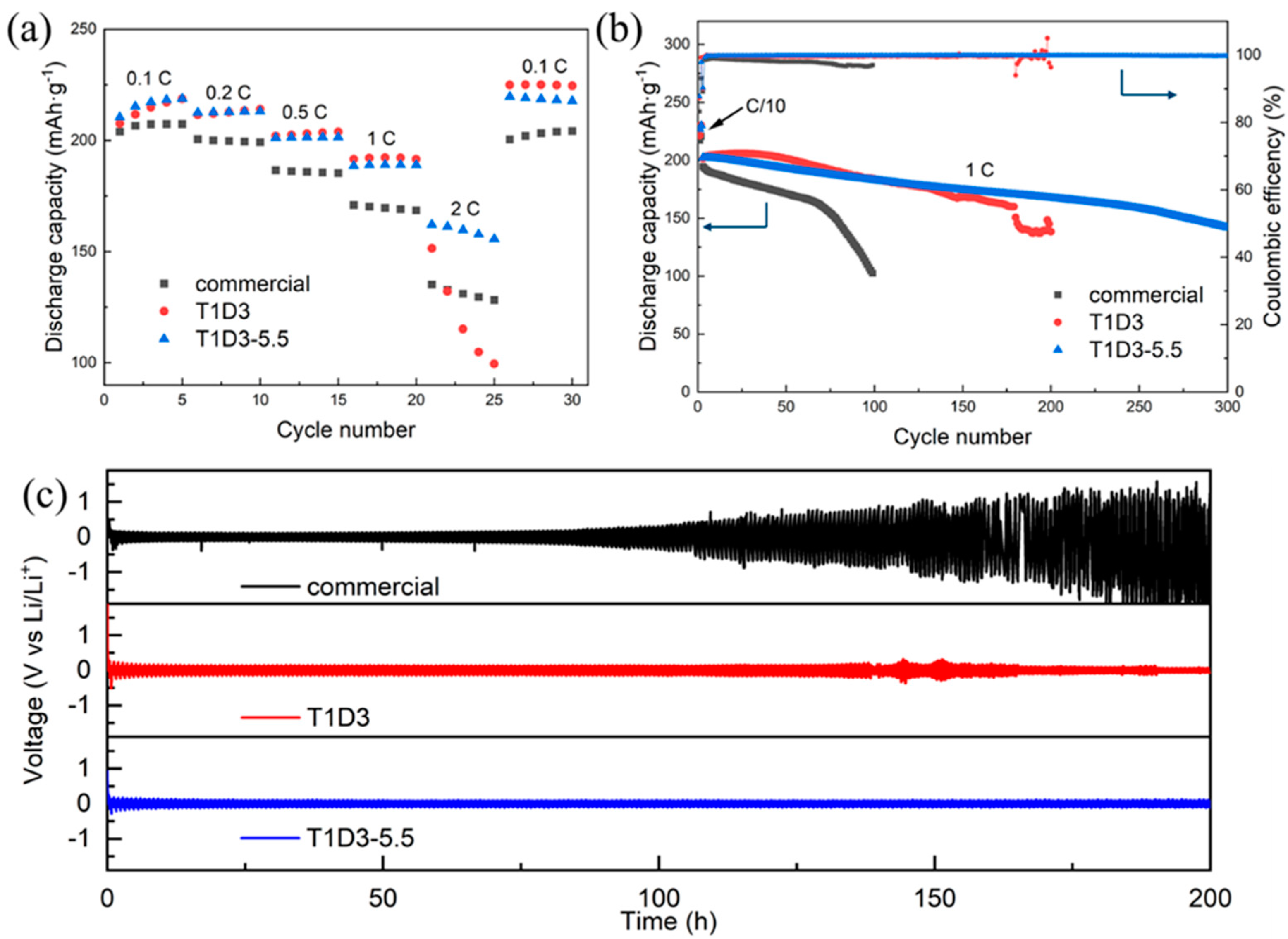
Figure 4.
(a–c) SEM top view of Li-metal anodes after 100 cycles in Li||NMC811 batteries with (a) commercial electrolyte; (b) T1D3; and (c) T1D3-5.5, respectively. (d)The relative content of various elements on the Li-metal surface after 100 cycles in three electrolytes obtained from EDX analysis.
Figure 4.
(a–c) SEM top view of Li-metal anodes after 100 cycles in Li||NMC811 batteries with (a) commercial electrolyte; (b) T1D3; and (c) T1D3-5.5, respectively. (d)The relative content of various elements on the Li-metal surface after 100 cycles in three electrolytes obtained from EDX analysis.
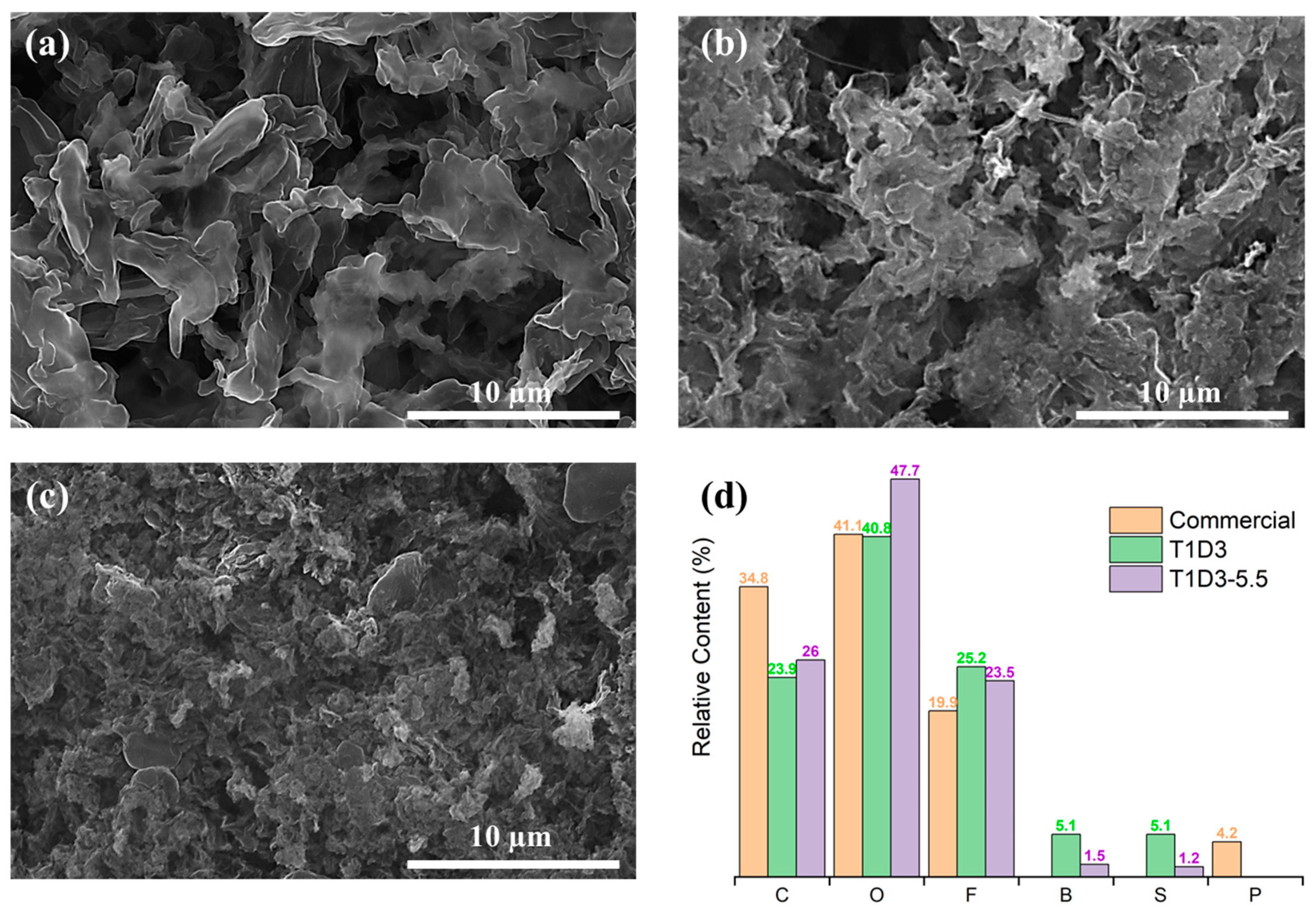
Figure 5.
(a–d) SEM top view of NMC811 cathode (a) before cycling, (b–d) after 100 cycles in (b) commercial electrolyte, (c) T1D3 and (d) T1D3-5.5, respectively. Red circles show pulverized particles. (e) Relative content of various elements on the NMC811 surface after 100 cycles in three different electrolytes, obtained by EDX analysis.


Table 1.
EIS fitting data of Li||NMC811 cells in three electrolytes after 2 cycles and 100 cycles.
| After 2 Cycles | After 100 Cycles | |||||
|---|---|---|---|---|---|---|
| Notation | Commercial | T1D3 | T1D3-5.5 | Commercial | T1D3 | T1D3-5.5 |
| Ro (Ω·cm−2) | 2.82 | 3.64 | 4.10 | 16.84 | 5.58 | 5.79 |
| R1 (Ω·cm−2) | 14.70 | 8.76 | 5.92 | 25.46 | 10.58 | 10.15 |
| R2 (Ω·cm−2) | 15.47 | 5.20 | 5.54 | 3.25 | 2.65 | 2.30 |
| RCT (Ω·cm−2) | 4.80 | 9.53 | 4.56 | 28.75 | 3.03 | 8.73 |
| Rtotal (Ω·cm−2) | 37.78 | 27.12 | 20.12 | 74.30 | 21.84 | 26.97 |
Disclaimer/Publisher’s Note: The statements, opinions and data contained in all publications are solely those of the individual author(s) and contributor(s) and not of MDPI and/or the editor(s). MDPI and/or the editor(s) disclaim responsibility for any injury to people or property resulting from any ideas, methods, instructions or products referred to in the content. |
© 2023 by the authors. Licensee MDPI, Basel, Switzerland. This article is an open access article distributed under the terms and conditions of the Creative Commons Attribution (CC BY) license (https://creativecommons.org/licenses/by/4.0/).
Share and Cite
MDPI and ACS Style
Qin, Z.; Wu, B.; Danilov, D.L.; Eichel, R.-A.; Notten, P.H.L. Dual-Salts Electrolyte with Fluoroethylene Carbonate Additive for High-Voltage Li-Metal Batteries. Batteries 2023, 9, 477. https://doi.org/10.3390/batteries9090477
AMA Style
Qin Z, Wu B, Danilov DL, Eichel R-A, Notten PHL. Dual-Salts Electrolyte with Fluoroethylene Carbonate Additive for High-Voltage Li-Metal Batteries. Batteries. 2023; 9(9):477. https://doi.org/10.3390/batteries9090477
Chicago/Turabian StyleQin, Zhizhen, Baolin Wu, Dmitri L. Danilov, Rüdiger-A. Eichel, and Peter H. L. Notten. 2023. "Dual-Salts Electrolyte with Fluoroethylene Carbonate Additive for High-Voltage Li-Metal Batteries" Batteries 9, no. 9: 477. https://doi.org/10.3390/batteries9090477
Note that from the first issue of 2016, this journal uses article numbers instead of page numbers. See further details here.