
A Symmetrical Leech-Inspired Soft Crawling Robot Based on Gesture Control


Abstract
1. Introduction
2. Gesture Design and Recognition Model Establishment
2.1. Theory of Gesture Recognition
- Append node: Concatenates texts into a single string;
- Make Literal String node: Generates text strings that serve as data table headers;
- Fill Data Table From CSV String node: Fills the data table with the converted string data.
2.2. Static Gesture
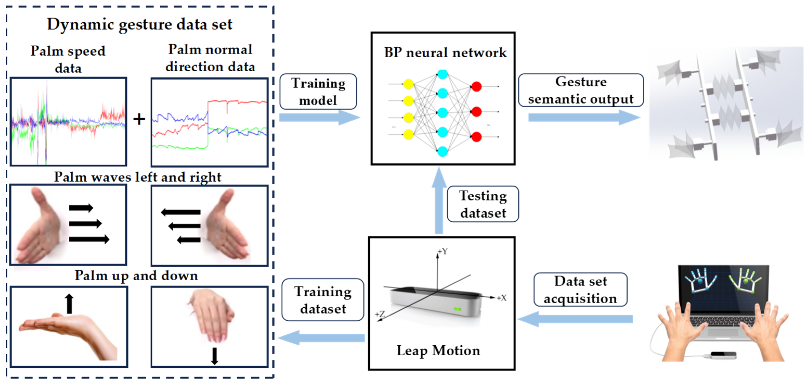
2.3. Dynamic Gesture
3. Design and Control of Soft Robot
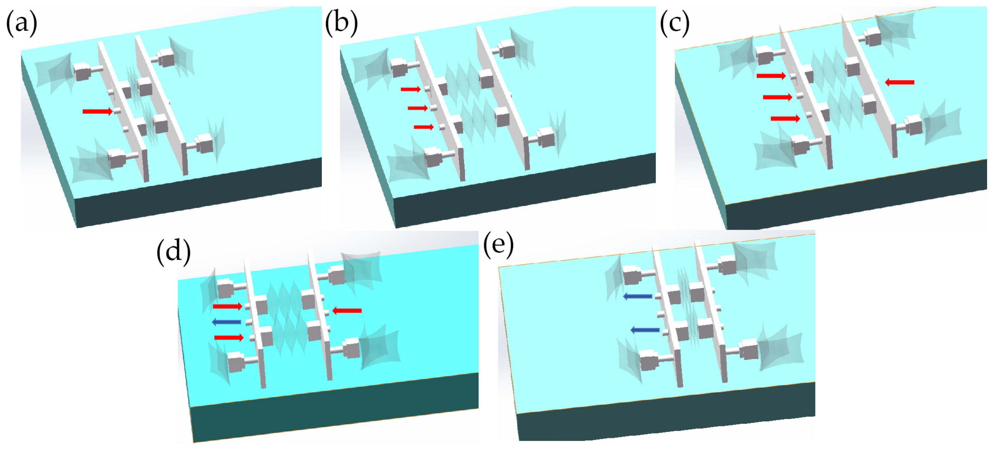
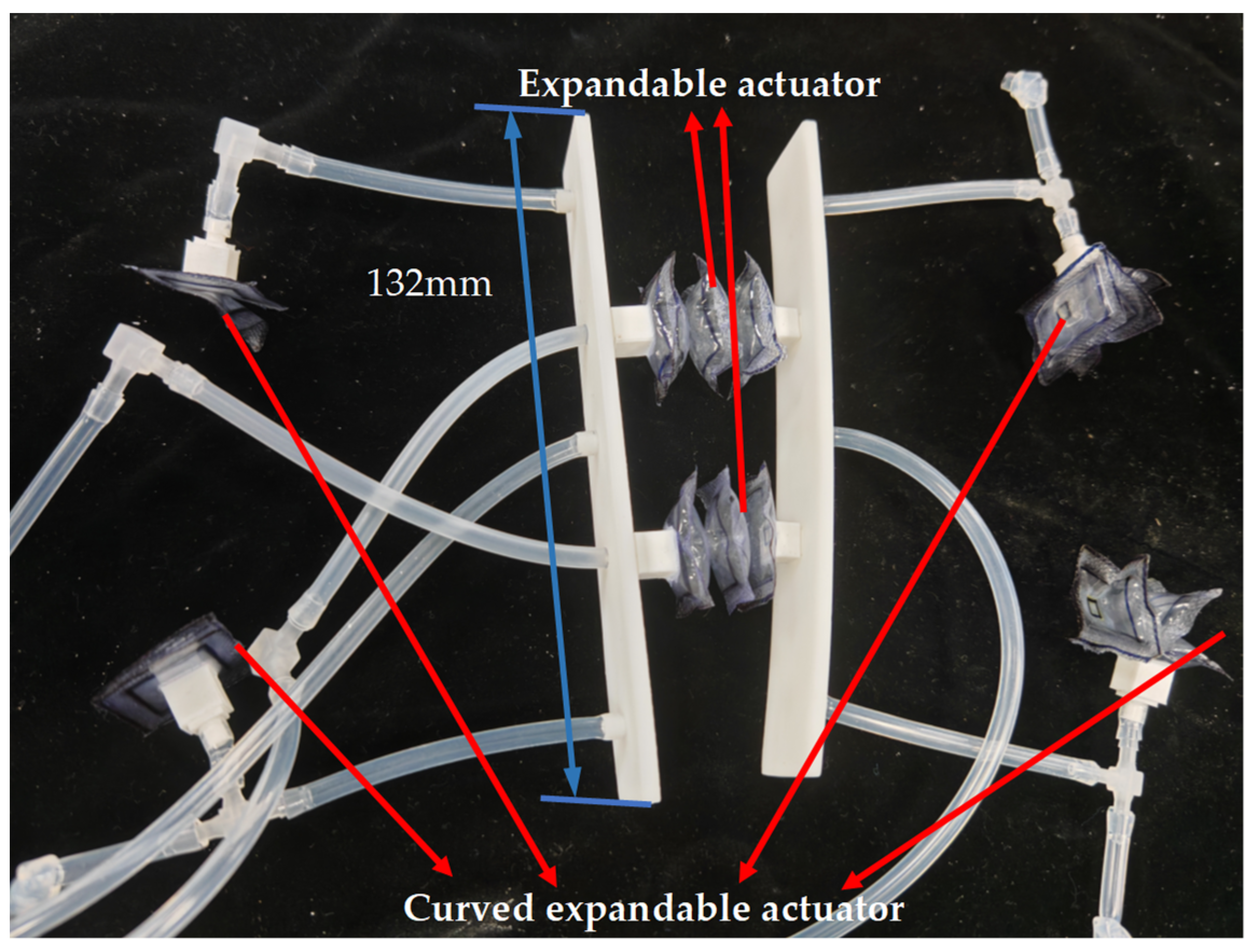
3.1. Design
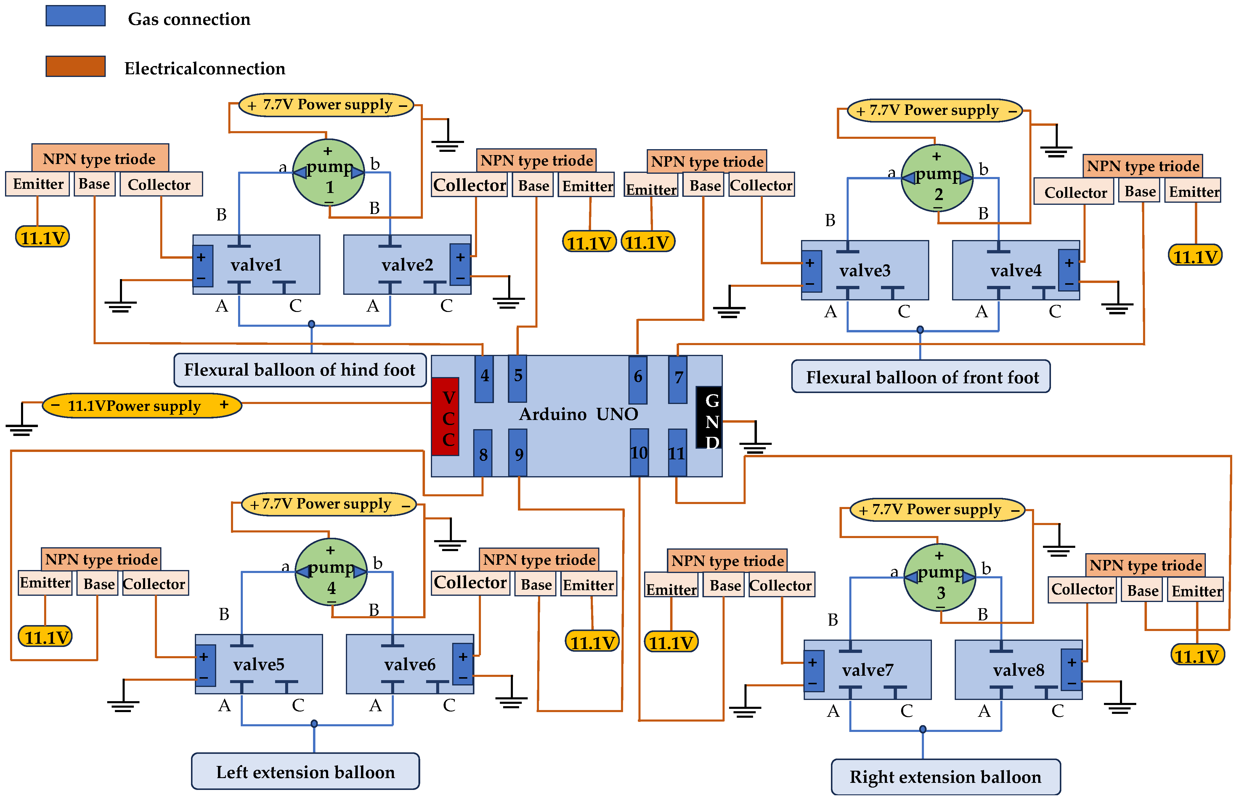
3.2. Control
4. Motion Experimental Verification of Soft Robot Based on Gesture Recognition
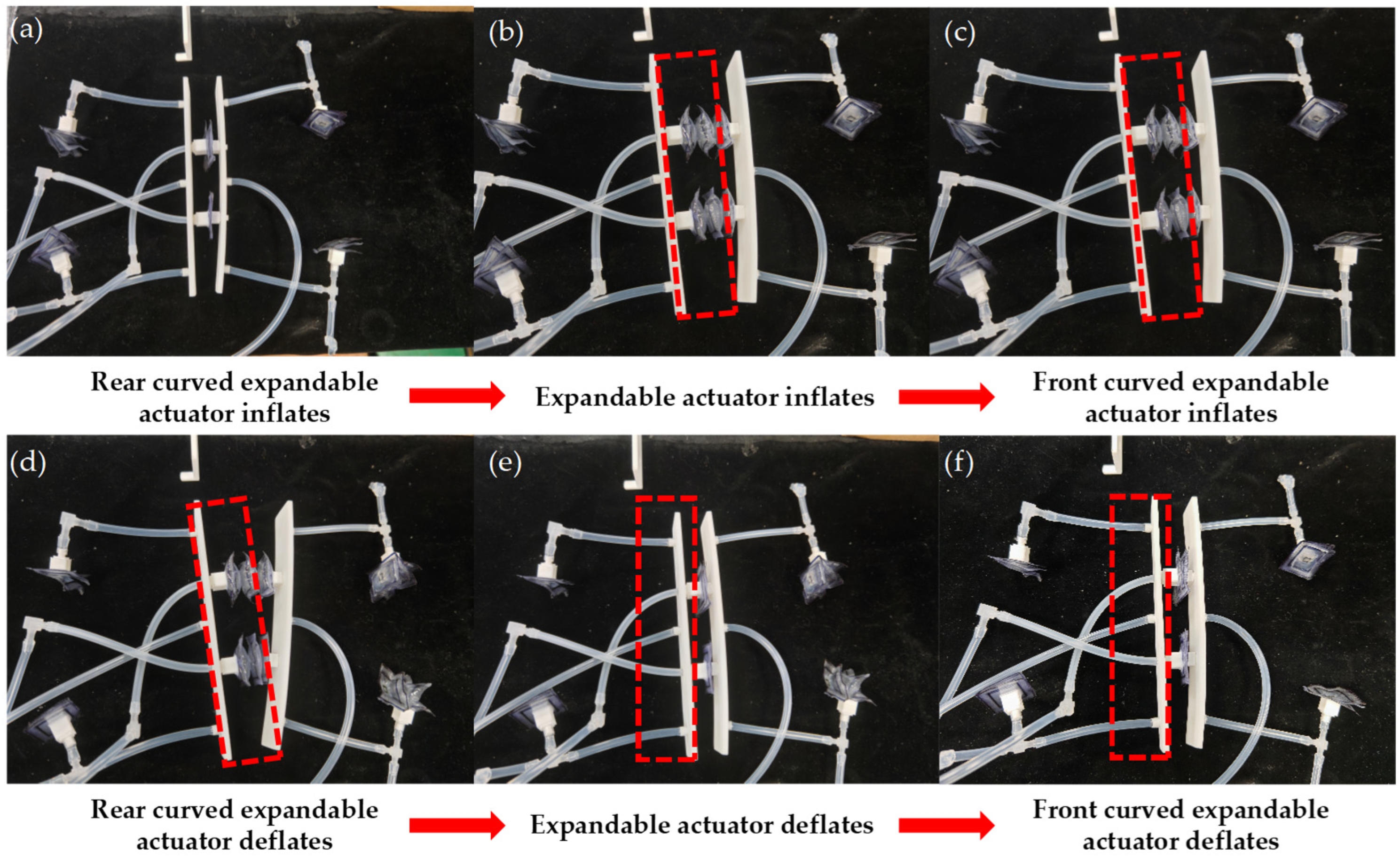
4.1. Linear Motion Experiment
- (1)
- The digital port 4 of the Arduino is set to a high level, and the solenoid valve 1 is activated. The two curved expandable actuators in the rear are inflated and bent, resulting in static friction with the ground, as shown in Figure 12a.
- (2)
- The digital ports 8 and 10 of the Arduino are set to a high level, and the solenoid valves 5 and 7 are activated. The left and right expandable actuators are inflated and the robot’s front support plate is forward, as shown in Figure 12b.
- (3)
- The digital port 6 of the Arduino is set to a high level, and the solenoid valve 3 is activated. The actuators of the front are inflated and bent, resulting in friction with the ground, as shown in Figure 12c.
- (4)
- The digital port 4 of the Arduino is set to a low level, the digital port 5 is set to a high level, and the solenoid valve 2 is activated. The two curved expandable actuators in the rear are deflated under negative pressure and detached from the ground, as shown in Figure 12d.
- (5)
- The digital ports 8 and 10 of Arduino are set to a low level, digital ports 9 and 11 are set to a high level, solenoid valves 6 and 8 are activated, two expandable actuators are deflated to negative pressure, and the robot moves forward due to friction between the curved actuators of the front and the ground, as shown in Figure 12e.
- (6)
- The digital port 6 of the Arduino is set to a low level, 7 to a high level, the solenoid valve 4 is activated, and the two front curved actuators are deflated under negative pressure and detached from the ground, as shown in Figure 12f.
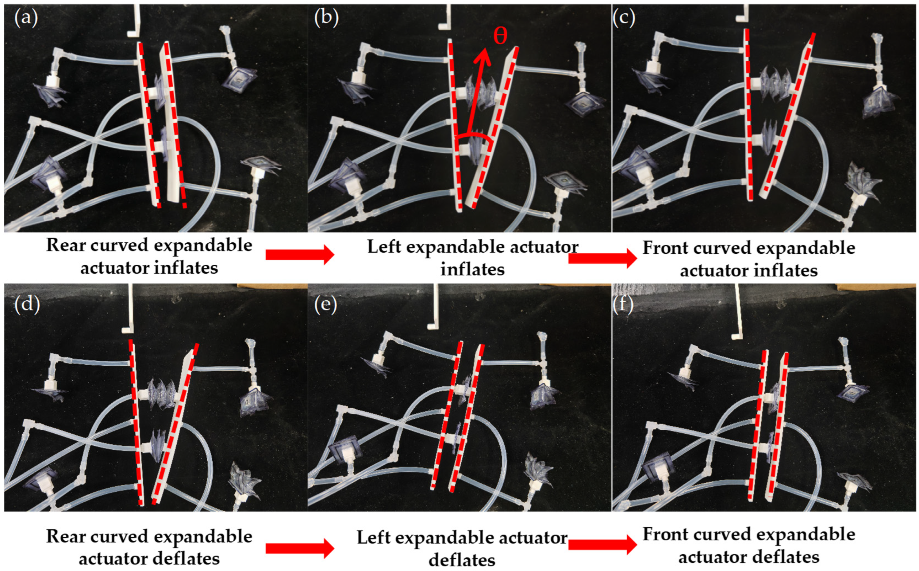
4.2. Directional Change in Motion Experiment
- (1)
- The digital port 4 of the Arduino is set to a high level, the solenoid valve 1 is activated, and the two curved expandable actuators in the rear are inflated and bent, resulting in static friction with the ground, as shown in Figure 13a;
- (2)
- The digital port 8 of the Arduino is set to a high level, the solenoid valve 5 is activated, and the left expandable actuator is inflated to make the front support plate of the robot rotate at a certain angle, as shown in Figure 13b;
- (3)
- The digital port 6 of the Arduino is set to a high level, and the solenoid valve 3 is activated, and the two front curved expandable actuators are inflated and bent, resulting in friction with the ground, as shown in Figure 13c;
- (4)
- The digital port 4 of the Arduino is set to a low level, the digital port 5 is set to a high level, the solenoid valve 2 is powered, and the two curved expandable actuators in the rear are deflated under negative pressure and detached from the ground, as shown in Figure 13d;
- (5)
- Arduino’s digital port 8 is set to a low level, digital port 9 is set to a high level, the solenoid valve is activated, the left expandable actuator is deflated to negative pressure, and the robot completes steering, as shown in Figure 13e;
- (6)
- The digital port 6 of the Arduino is set to a low level, 7 to a high level, the solenoid valve 4 is activated, and the two front curved expandable actuators are deflated under negative pressure and detached from the ground, as shown in Figure 13f.
5. Conclusions
Author Contributions
Funding
Institutional Review Board Statement
Informed Consent Statement
Data Availability Statement
Conflicts of Interest
References
- Kim, S.; Laschi, C.; Trimmer, B. Soft Robotics: A Bioinspired Evolution in Robotics. Trends Biotechnol. 2013, 31, 287–294. [Google Scholar] [CrossRef]
- Trimmer, B. Soft Robots and Society. Soft Robot. 2015, 2, 1–2. [Google Scholar] [CrossRef]
- Stokes, A.A.; Shepherd, R.F.; Morin, S.A.; Ilievski, F.; Whitesides, G.M. A Hybrid Combining Hard and Soft Robots. Soft Robot. 2013, 1, 70–74. [Google Scholar] [CrossRef]
- Rus, D.; Tolley, M.T. Design, Fabrication and Control of Soft Robots. Nature 2015, 521, 467–475. [Google Scholar] [CrossRef]
- Cao, J.; Qin, L.; Liu, J.; Ren, Q.; Foo, C.C.; Wang, H.; Lee, H.P.; Zhu, J. Untethered Soft Robot Capable of Stable Locomotion Using Soft Electrostatic Actuators. Extrem. Mech. Lett. 2018, 21, 9–16. [Google Scholar] [CrossRef]
- Yap, Y.L.; Sing, S.L.; Yeong, W.Y. A Review of 3D Printing Processes and Materials for Soft Robotics. Rapid Prototyp. J. 2020, 26, 1345–1361. [Google Scholar] [CrossRef]
- Iida, F.; Laschi, C. Soft Robotics: Challenges and Perspectives. Procedia Comput. Sci. 2011, 7, 99–102. [Google Scholar] [CrossRef]
- Heung, H.; Chiu, P.W.Y.; Li, Z. Design and Prototyping of a Soft Earthworm-like Robot Targeted for GI Tract Inspection. In Proceedings of the 2016 IEEE International Conference on Robotics and Biomimetics (ROBIO), Qingdao, China, 3–7 December 2016; IEEE: New York, NY, USA, 2016; pp. 497–502. [Google Scholar]
- Lin, Y.; Xu, Y.-X.; Juang, J.-Y. Single-Actuator Soft Robot for In-Pipe Crawling. Soft Robot. 2023, 10, 174–186. [Google Scholar] [CrossRef] [PubMed]
- Ozkan-Aydin, Y.; Liu, B.; Ferrero, A.C.; Seidel, M.; Hammond, F.L.; Goldman, D.I. Lateral Bending and Buckling Aids Biological and Robotic Earthworm Anchoring and Locomotion. Bioinspir. Biomim. 2021, 17, 016001. [Google Scholar] [CrossRef]
- Acome, E.; Mitchell, S.K.; Morrissey, T.G.; Emmett, M.B.; Benjamin, C.; King, M.; Radakovitz, M.; Keplinger, C. Hydraulically Amplified Self-Healing Electrostatic Actuators with Muscle-like Performance. Science 2018, 359, 61–65. [Google Scholar] [CrossRef] [PubMed]
- Zhao, J.; Yu, T.; Zhang, Y.; Sun, H.; Xu, M. Electrostatically Driven Kresling Origami Soft Pump. IEEE Robot. Autom. Lett. 2024, 9, 7166–7173. [Google Scholar] [CrossRef]
- Wehner, M.; Truby, R.L.; Fitzgerald, D.J.; Mosadegh, B.; Whitesides, G.M.; Lewis, J.A.; Wood, R.J. An Integrated Design and Fabrication Strategy for Entirely Soft, Autonomous Robots. Nature 2016, 536, 451–455. [Google Scholar] [CrossRef] [PubMed]
- Loepfe, M.; Schumacher, C.M.; Lustenberger, U.B.; Stark, W.J. An Untethered, Jumping Roly-Poly Soft Robot Driven by Combustion. Soft Robot. 2015, 2, 33–41. [Google Scholar] [CrossRef]
- Bartlett, N.W.; Tolley, M.T.; Overvelde, J.T.B.; Weaver, J.C.; Mosadegh, B.; Bertoldi, K.; Whitesides, G.M.; Wood, R.J. A 3D-Printed, Functionally Graded Soft Robot Powered by Combustion. Science 2015, 349, 161–165. [Google Scholar] [CrossRef] [PubMed]
- Lai, J.; Lu, B.; Huang, K.; Chu, H.K. Gesture-Based Steering Framework for Redundant Soft Robots. IEEE-ASME Trans. Mechatron. 2024, 29, 4651–4663. [Google Scholar] [CrossRef]
- Sturman, D.; Zeltzer, D. A Survey of Glove-Based Input. IEEE Comput. Graph. Appl. 1994, 14, 30–39. [Google Scholar] [CrossRef]
- Artal-Sevil, J.S.; Montanes, J.L. Development of a Robotic Arm and Implementation of a Control Strategy for Gesture Recognition through Leap Motion Device. In Proceedings of the 2016 Technologies Applied to Electronics Teaching (TAEE 2016), Seville, Spain, 22–24 June 2016; IEEE: New York, NY, USA, 2016. [Google Scholar]
- Zhang, X.; Zhang, R.; Chen, L.; Zhang, X. Natural Gesture Control of a Delta Robot Using Leap Motion. J. Phys.: Conf. Ser. 2019, 1187, 032042. [Google Scholar] [CrossRef]
- Xu, Y.; Chen, L. The Attitude Control Method and Realization of Micro Rotor-Craft Based on Natural Interaction. In Proceedings of the 2015 2nd International Conference on Machinery, Materials Engineering, Chemical Engineering and Biotechnology (MMECEB), Chongqing, China, 28–29 November 2015; Tsing, L., Lee, K., Eds.; Atlantis Press: Paris, France, 2016; Volume 49, pp. 348–351. [Google Scholar]
- Li, C.; Fahmy, A.; Sienz, J. Development of a Neural Network-Based Control System for the DLR-HIT II Robot Hand Using Leap Motion. IEEE Access 2019, 7, 136914–136923. [Google Scholar] [CrossRef]
- Oguntosin, V.; Abdulkareem, A. Hand Gesture Control and Design of a Rotary Pneumatic Soft Actuator Using Leap Motion Sensor. Int. J. Intell. Robot. 2020, 4, 328–341. [Google Scholar] [CrossRef]
- Avola, D.; Bernardi, M.; Cinque, L.; Foresti, G.L.; Massaroni, C. Exploiting Recurrent Neural Networks and Leap Motion Controller for the Recognition of Sign Language and Semaphoric Hand Gestures. IEEE Trans. Multimed. 2019, 21, 234–245. [Google Scholar] [CrossRef]
- Li, C.; Fahmy, A.; Sienz, J. An Augmented Reality Based Human-Robot Interaction Interface Using Kalman Filter Sensor Fusion. Sensors 2019, 19, 4586. [Google Scholar] [CrossRef] [PubMed]
- Li, H.; Wu, L.; Wang, H.; Han, C.; Quan, W.; Zhao, J. Hand Gesture Recognition Enhancement Based on Spatial Fuzzy Matching in Leap Motion. IEEE Trans. Ind. Inform. 2020, 16, 1885–1894. [Google Scholar] [CrossRef]

| Tip of Finger | Threshold Value |
|---|---|
| Index finger | X value: −115 ± 5°; Y: 50 ± 5°; Z: 71 ± 5° |
| Middle finger | X value: −125 ± 5°; Y: 63 ± 5°; Z: 62 ± 5° |
| Arduino Digital Port | 4 | 5 | 6 | 7 | 8 | 9 | 10 | 11 |
|---|---|---|---|---|---|---|---|---|
| Solenoid valve number | 1 | 2 | 3 | 4 | 5 | 6 | 7 | 8 |
| Actuator | Pump | Valve |
|---|---|---|
| Two curved actuators in the rear | 1 | 1, 2 |
| Two curved actuators in the front | 2 | 3, 4 |
| Left expandable actuator | 3 | 5, 6 |
| Right expandable actuator | 4 | 7, 8 |
| Gesture | Robot Motion |
|---|---|
| Make a fist | Start moving |
| Open palms | Stop moving |
| Extend the index finger | Turn right |
| Extend the index finger and middle finger at the same time | Turn left |
Disclaimer/Publisher’s Note: The statements, opinions and data contained in all publications are solely those of the individual author(s) and contributor(s) and not of MDPI and/or the editor(s). MDPI and/or the editor(s) disclaim responsibility for any injury to people or property resulting from any ideas, methods, instructions or products referred to in the content. |
© 2025 by the authors. Licensee MDPI, Basel, Switzerland. This article is an open access article distributed under the terms and conditions of the Creative Commons Attribution (CC BY) license (https://creativecommons.org/licenses/by/4.0/).
Share and Cite
Li, J.; Liu, R.; Zhang, T.; Liu, J. A Symmetrical Leech-Inspired Soft Crawling Robot Based on Gesture Control. Biomimetics 2025, 10, 35. https://doi.org/10.3390/biomimetics10010035
Li J, Liu R, Zhang T, Liu J. A Symmetrical Leech-Inspired Soft Crawling Robot Based on Gesture Control. Biomimetics. 2025; 10(1):35. https://doi.org/10.3390/biomimetics10010035
Chicago/Turabian StyleLi, Jiabiao, Ruiheng Liu, Tianyu Zhang, and Jianbin Liu. 2025. "A Symmetrical Leech-Inspired Soft Crawling Robot Based on Gesture Control" Biomimetics 10, no. 1: 35. https://doi.org/10.3390/biomimetics10010035
APA StyleLi, J., Liu, R., Zhang, T., & Liu, J. (2025). A Symmetrical Leech-Inspired Soft Crawling Robot Based on Gesture Control. Biomimetics, 10(1), 35. https://doi.org/10.3390/biomimetics10010035