

The Design of the Dummy Arm: A Verification Tool for Arm Exoskeleton Development

Abstract
:1. Introduction
2. Materials and Methods
2.1. Dummy Arm Design Requirements
- A representative forearm anthropometric to fit the DAROR interface sleeve(s);
- A similar DAROR range of motion; see Table 1;
- An attachment at the base of the frame at the shoulder joint;
- An adjustable (linear) eJimp;
- An interface to attach additional objects at the wrist location.
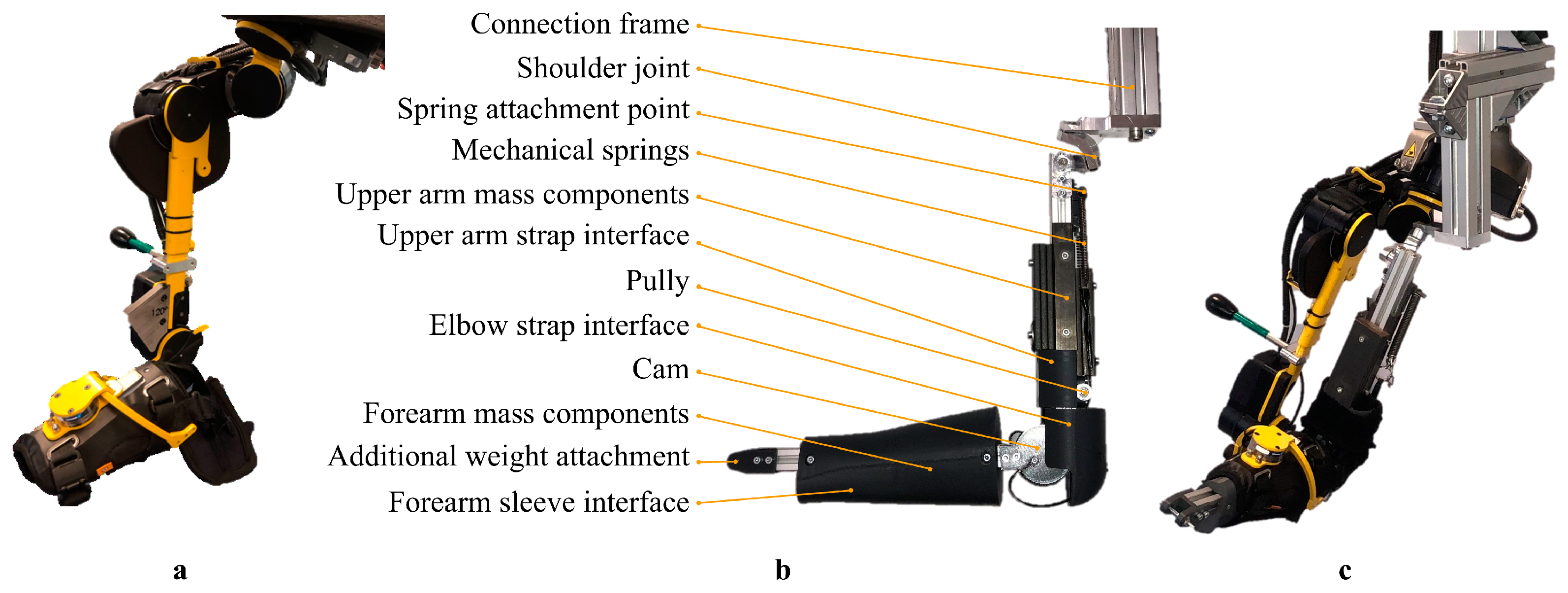
2.2. Dummy Arm Design
2.2.1. Shoulder Joint
2.2.2. Elbow Joint
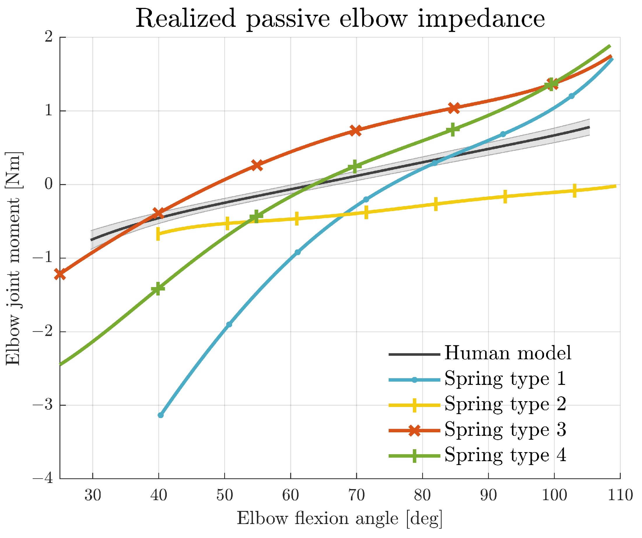
2.2.3. Passive Elbow Joint Impedance
2.2.4. Connection Frame
2.2.5. Mass and Centre of Mass of the Upper and Lower Arm
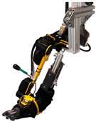
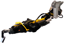
2.2.6. Verification of Design
3. Results
3.1. Joint Impedance Realisation
3.2. Activities of Daily Living
3.3. Cost-Analysis
4. Discussion
4.1. Limitations
4.2. Recommendations
5. Conclusions
Supplementary Materials
Author Contributions
Funding
Institutional Review Board Statement
Data Availability Statement
Acknowledgments
Conflicts of Interest
Abbreviations
| pJimp | passive joint impedance |
| eJimp | passive elbow joint impedance |
| CoM | centre of mass |
| DAROR | Duchenne ARm Orthosis |
| GH | glenohumeral |
| CAD | Computer Aided Design |
References
- Barrutia, W.S.; Bratt, J.; Ferris, D.P. A Human Lower Limb Mechanical Phantom for the Testing of Knee Exoskeletons. IEEE Trans. Neural Syst. Rehabil. Eng. 2023, 31, 2497–2506. [Google Scholar] [CrossRef] [PubMed]
- Gull, M.A.; Bai, S.; Bak, T. A review on design of upper limb exoskeletons. Robotics 2020, 9, 16. [Google Scholar] [CrossRef]
- Dollar, A.M.; Herr, H. Lower extremity exoskeletons and active orthoses: Challenges and state-of-the-art. IEEE Trans. Robot. 2008, 24, 144–158. [Google Scholar] [CrossRef]
- De Looze, M.P.; Bosch, T.; Krause, F.; Stadler, K.S.; O’Sullivan, L.W. Exoskeletons for industrial application and their potential effects on physical work load. Ergonomics 2016, 56, 671–681. [Google Scholar] [CrossRef] [PubMed]
- Dežman, M.; Massardi, S.; Pinto-Fernandez, D.; Grosu, V.; Rodriguez-Guerrero, C.; Babič, J.; Torricelli, D. A mechatronic leg replica to benchmark human–exoskeleton physical interactions. Bioinspiration Biomim. 2023, 18, 036009. [Google Scholar] [CrossRef] [PubMed]
- Koopman, A.S.; Kingma, I.; Faber, G.S.; de Looze, M.P.; van Dieën, J.H. Effects of a passive exoskeleton on the mechanical loading of the low back in static holding tasks. J. Biomech. 2019, 83, 97–103. [Google Scholar] [CrossRef] [PubMed]
- Van Dijk, W.; Van de Wijdeven, T.; Holscher, M.; Barents, R.; Könemann, R.; Krause, F.; Koerhuis, C.L. Exobuddy-A non-anthropomorphic quasi-passive exoskeleton for load carrying assistance. In Proceedings of the 2018 7th IEEE International Conference on Biomedical Robotics and Biomechatronics (Biorob), Enschede, The Netherlands, 26–29 August 2018; pp. 336–341. [Google Scholar] [CrossRef]
- Plaza, A.; Hernandez, M.; Puyuelo, G.; Garces, E.; Garcia, E. Lower-Limb Medical and Rehabilitation Exoskeletons: A Review of the Current Designs. IEEE Rev. Biomed. Eng. 2023, 16, 278–291. [Google Scholar] [CrossRef] [PubMed]
- Gandolla, M.; Antonietti, A.; Longatelli, V.; Pedrocchi, A. The Effectiveness of Wearable Upper Limb Assistive Devices in Degenerative Neuromuscular Diseases: A Systematic Review and Meta-Analysis. Front. Bioeng. Biotechnol. 2020, 7, 1–16. [Google Scholar] [CrossRef] [PubMed]
- Chandler, R.F.; Clauser, C.E.C.; McConville, J.T.J.J.T.; Reynolds, H.M.; Young, J.W.; Yough, J. Investigation of Inertial Properties of the Human Body; Technical Report March; U.S. Department of Transportation: Washington, DC, USA, 1975. [Google Scholar]
- Clauser, C.E.; McConville, J.T.; Young, J.W. Weight, Volume, and Center of Mass of Segments of the Human Body; Technical Report; Aerospace Medical Research Laboratory: Wright-Paterson Air Force Base, OH, USA, 1969. [Google Scholar]
- Filius, S.J.; Keemink, A.Q.L.; Meijneke, C.; Gregor, W.; Kuenen, T.; Janssen, M.; Harlaar, J.; Kooij, H.V.D. A 4DOF Impedance-Based Exoskeleton with Weight and Elbow Stiffness Compensation: For Duchenne Brooke Scale 4, Department of BioMechanical Engineering, Delft University of Technology: Delft, The Netherlands, (Unpublished).
- Maggioni, S.; Melendez-Calderon, A.; Van Asseldonk, E.; Klamroth-Marganska, V.; Lünenburger, L.; Riener, R.; Van Der Kooij, H. Robot-aided assessment of lower extremity functions: A review. J. Neuroeng. Rehabil. 2016, 13, 1–25. [Google Scholar] [CrossRef] [PubMed]
- Filius, S.J.; Harlaar, J.; Alberts, L.; Houwen-van Opstal, S.; van der Kooij, H.; Janssen, M.M. Design requirements of upper extremity supports for daily use in Duchenne muscular dystrophy with severe muscle weakness. J. Rehabil. Assist. Technol. Eng. 2024, 11, 1–18. [Google Scholar] [CrossRef] [PubMed]
- Noda, T.; Teramae, T.; Ugurlu, B.; Morimoto, J. Development of an upper limb exoskeleton powered via pneumatic electric hybrid actuators with bowden cable. In Proceedings of the 2014 IEEE/RSJ International Conference on Intelligent Robots and Systems, Chicago, IL, USA, 14–18 September 2014; pp. 3573–3578. [Google Scholar] [CrossRef]
- Madani, T.; Daachi, B.; Djouani, K. Non-singular terminal sliding mode controller: Application to an actuated exoskeleton. Mechatronics 2016, 33, 136–145. [Google Scholar] [CrossRef]
- Dávila-Vilchis, J.M.; LAZ-Avilés; Ávila Vilchis, J.C.; Vilchis-González, A.H. Design Methodology for Soft Wearable Devices—The MOSAR Case. Appl. Sci. 2019, 9, 4727. [Google Scholar] [CrossRef]
- Toth, A.; Pilissy, T.; Bauer, M.O.; Al-Absi, G.; David, S.; Fazekas, G. Testing the Limit Range of Motion Safety Function of Upper Limb Rehabilitation Robots with an Anthropometrically Adjustable and Sensorized Dummy Limb. In Proceedings of the 2022 International Conference on Rehabilitation Robotics (ICORR), Rotterdam, The Netherlands, 25–29 July 2022; pp. 25–29. [Google Scholar] [CrossRef]
- Bessler-Etten, J.; Schaake, L.; Prange-Lasonder, G.B.; Buurke, J.H. Assessing effects of exoskeleton misalignment on knee joint load during swing using an instrumented leg simulator. J. Neuroeng. Rehabil. 2022, 19, 13. [Google Scholar] [CrossRef]
- Contini, R. Body Segment Parameters, Part II; Technical Report. Available online: https://citeseerx.ist.psu.edu/document?repid=rep1&type=pdf&doi=eb1971ff961ba567256c52fa89ad2be5e25ec9f9#page=5 (accessed on 15 January 2023).
- Dempster, W.T.; Gaughran, G.R.L. Properties of body segments based on size and weight. Am. J. Anat. 1967, 120, 33–54. [Google Scholar] [CrossRef]
- Drillis, R.; Contini, R.; Bluestein, M. Body Segment Parameters A survey of Measurement Techniques; Technical Report; Artifical Limbs: Washington, DC, USA, 1964. [Google Scholar]
- Wu, G.; Van Der Helm, F.C.; Veeger, H.E.; Makhsous, M.; Van Roy, P.; Anglin, C.; Nagels, J.; Karduna, A.R.; McQuade, K.; Wang, X.; et al. ISB recommendation on definitions of joint coordinate systems of various joints for the reporting of human joint motion—Part II: Shoulder, elbow, wrist and hand. J. Biomech. 2005, 38, 981–992. [Google Scholar] [CrossRef] [PubMed]
- Doorenbosch, C.A.; Harlaar, J.; Veeger, D.H. The globe system: An unambiguous description of shoulder positions in daily life movements. J. Rehabil. Res. Dev. 2003, 40, 147–155. [Google Scholar] [CrossRef] [PubMed]
- Stienen, A.H.; Keemink, A.Q. Visualization of shoulder range of motion for clinical diagnostics and device development. In Proceedings of the 2015 IEEE International Conference on Rehabilitation Robotics (ICORR), Singapore, 11–14 August 2015; pp. 816–821. [Google Scholar] [CrossRef]
- Filius, S.; Janssen, M.; van der Kooij, H.; Harlaar, J. Comparison of Lower Arm Weight and Passive Elbow Joint Impedance Compensation Strategies in Non-Disabled Participants. In Proceedings of the 2023 International Conference on Rehabilitation Robotics (ICORR), Singapore, 24–28 September 2023; pp. 1–6. [Google Scholar] [CrossRef]
- Tidwell, P.H. Wrapping Cam Mechanisms. Ph.D. Thesis, Virginia Polytechnic Institute and State University, Blacksburg, VA, USA, 1995. [Google Scholar]
- Schroeder, J.S.; Perry, J.C.; Beyerlein, S.W. Application of Wrapping Cams in an Unpowered, Upper-Limb Assistive Device. Ph.D. Thesis, University of Idaho, Moscow, ID, USA, 2016. [Google Scholar]
- Story, A. Right Hand Reference. 2020. Available online: https://grabcad.com/library/right-hand-reference-1 (accessed on 10 January 2023).
- Schiele, A.; Van Der Helm, F.C. Kinematic design to improve ergonomics in human machine interaction. IEEE Trans. Neural Syst. Rehabil. Eng. 2006, 14, 456–469. [Google Scholar] [CrossRef] [PubMed]


| Joint Rotation | Target |
|---|---|
| GH elevation | 11° to 137° |
| GH horizontal | −46° to 138° |
| GH axial | −113° to 65° |
| El flexion/extension | 2° to 120° |
| Human Model | Dummy Arm | CAD | ||||
|---|---|---|---|---|---|---|
|
Mass a kg |
CoM b mm |
Mass kg |
CoM mm |
Mass kg | CoM c mm | |
| UA | 1.6–2 | 137 | 1.8 | 140 | 1.7 | |
| FA | 0.9–1.1 | 106 | 1.0 | 110 | 1.0 | |
| 1st-Order Fit Nm/rad x + Nm | z (M ± SD) deg | |
|---|---|---|
| Human model | 66 ± 11 | |
| Spring type 1 | 74 | |
| Spring type 2 | - | |
| Spring type 3 | 48 | |
| Spring type 4 | 63 |
| a. Tabletop Activities | b. Feeding Activities | c. Lifted Object (200 g) |
|---|---|---|
 |  |  |
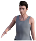 |  | 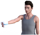 |
| Material | Costs |
|---|---|
| Bearings | EUR 13.50 |
| Frame | EUR 6.00 (550 mm) |
| Mounting materials | EUR 15.00 |
| Axes | EUR 1.00 (200 mm) |
| Weights | EUR 12.50 (1.9 kg) |
| Springs | EUR 11.00 |
| Belt and pulleys | EUR 13.00 |
| PLA filament | EUR 6.50 (280 g) |
| Total | EUR 78.50 |
Disclaimer/Publisher’s Note: The statements, opinions and data contained in all publications are solely those of the individual author(s) and contributor(s) and not of MDPI and/or the editor(s). MDPI and/or the editor(s) disclaim responsibility for any injury to people or property resulting from any ideas, methods, instructions or products referred to in the content. |
© 2024 by the authors. Licensee MDPI, Basel, Switzerland. This article is an open access article distributed under the terms and conditions of the Creative Commons Attribution (CC BY) license (https://creativecommons.org/licenses/by/4.0/).
Share and Cite
Filius, S.J.; van der Burgh, B.J.; Harlaar, J. The Design of the Dummy Arm: A Verification Tool for Arm Exoskeleton Development. Biomimetics 2024, 9, 579. https://doi.org/10.3390/biomimetics9100579
Filius SJ, van der Burgh BJ, Harlaar J. The Design of the Dummy Arm: A Verification Tool for Arm Exoskeleton Development. Biomimetics. 2024; 9(10):579. https://doi.org/10.3390/biomimetics9100579
Chicago/Turabian StyleFilius, Suzanne J., Bas J. van der Burgh, and Jaap Harlaar. 2024. "The Design of the Dummy Arm: A Verification Tool for Arm Exoskeleton Development" Biomimetics 9, no. 10: 579. https://doi.org/10.3390/biomimetics9100579
APA StyleFilius, S. J., van der Burgh, B. J., & Harlaar, J. (2024). The Design of the Dummy Arm: A Verification Tool for Arm Exoskeleton Development. Biomimetics, 9(10), 579. https://doi.org/10.3390/biomimetics9100579