
Development of a Vertical Submerging and Emerging Bat-Ray-Inspired Underwater Vehicle

 , ,
, ,  ,
,  , and
, and 
Abstract
1. Introduction
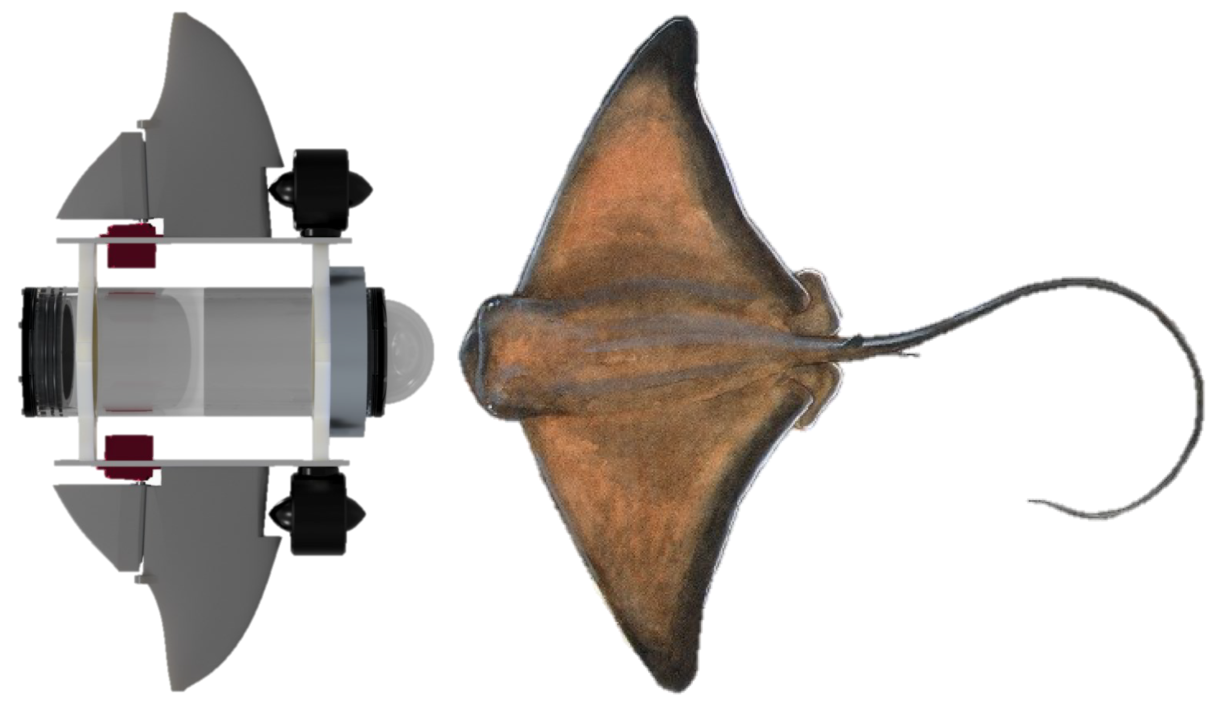
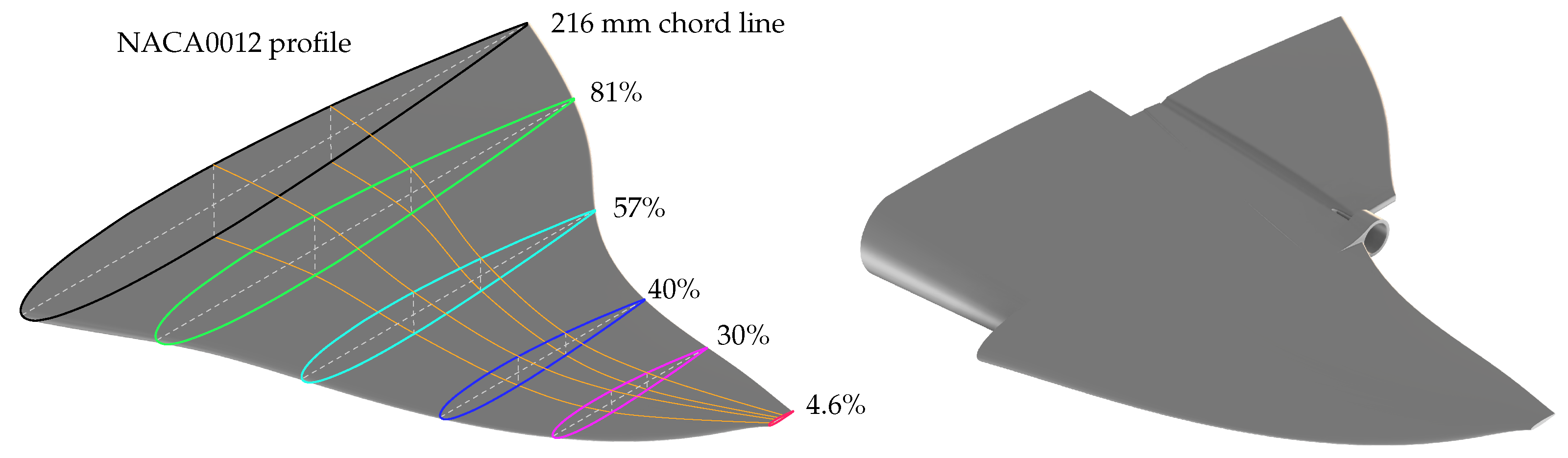
2. Bio-Inspired Robot Design
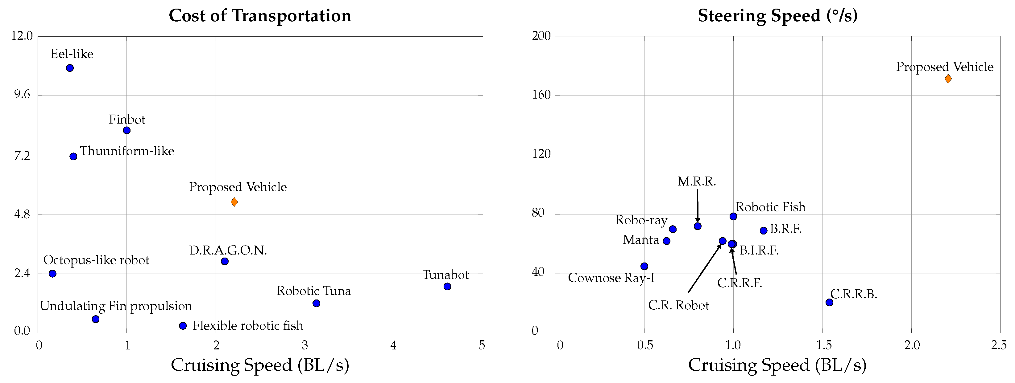
2.1. Speed
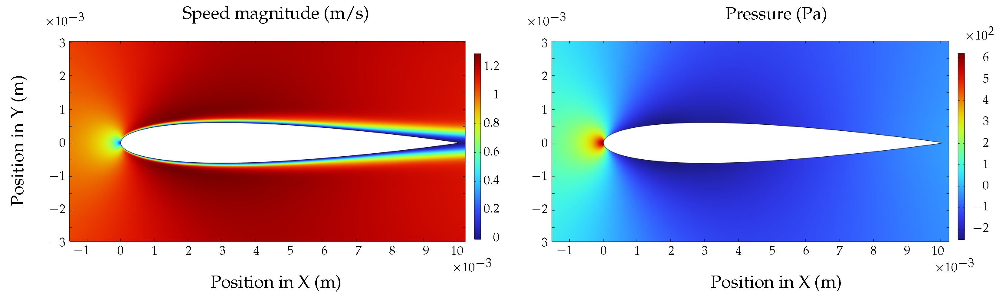
2.2. Efficiency
2.3. Maneuverability and Agility
2.4. Bio-Inspired Rajiform Underwater Robot
3. Modeling, Simulation, and Control
3.1. Mathematical Model
3.1.1. Gravitational Forces
3.1.2. Buoyancy Forces
3.1.3. Added Mass Forces
3.1.4. Damping Forces
3.1.5. Propeller Forces
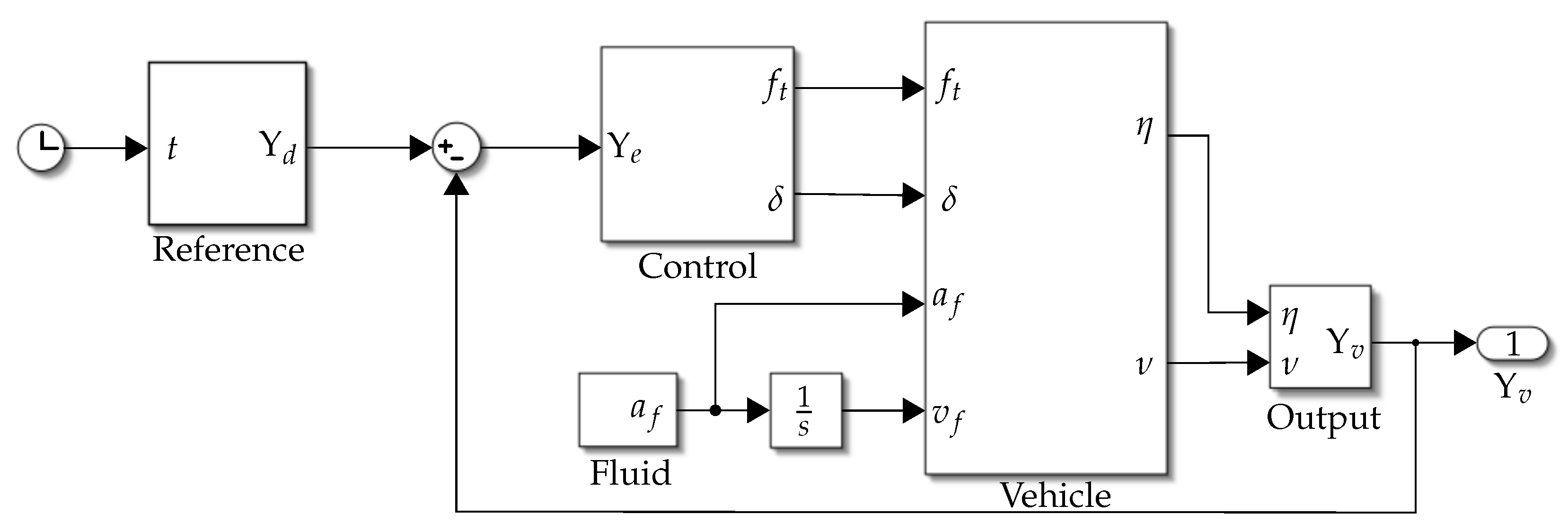
3.2. Simulation
3.3. Control
4. Results
4.1. Simulation Results
4.1.1. Test 1: Vertical Submerging and Emerging
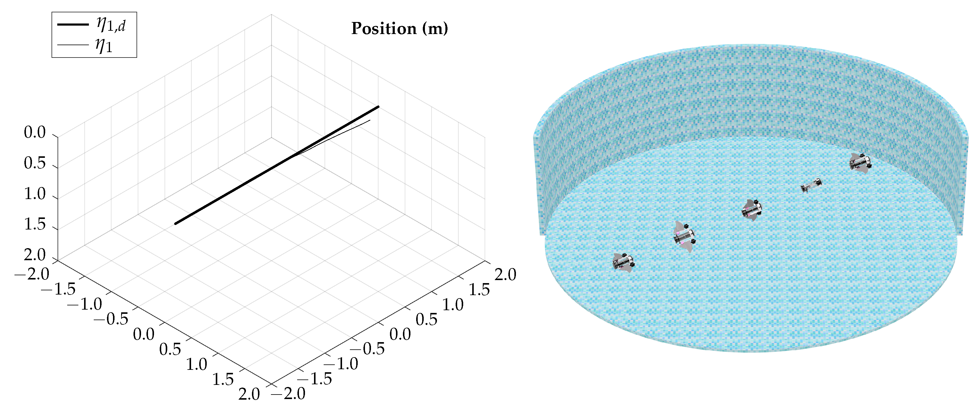
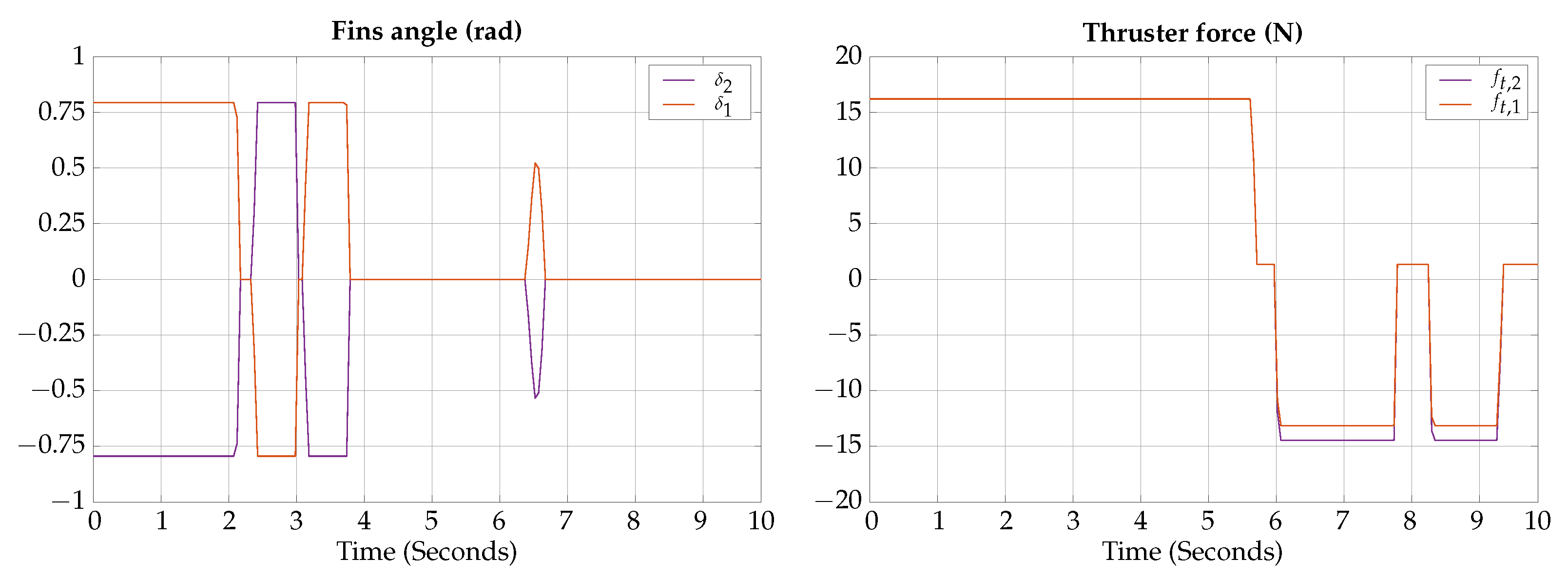
4.1.2. Test 2: Horizontal Gliding
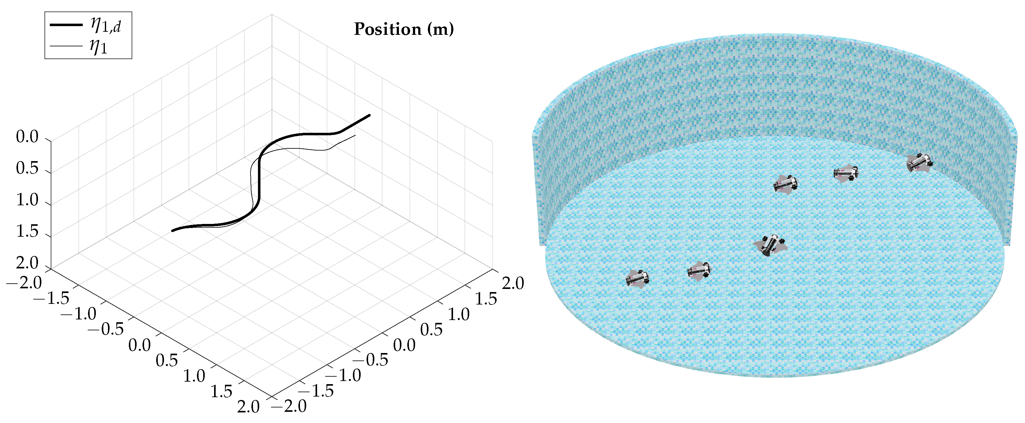
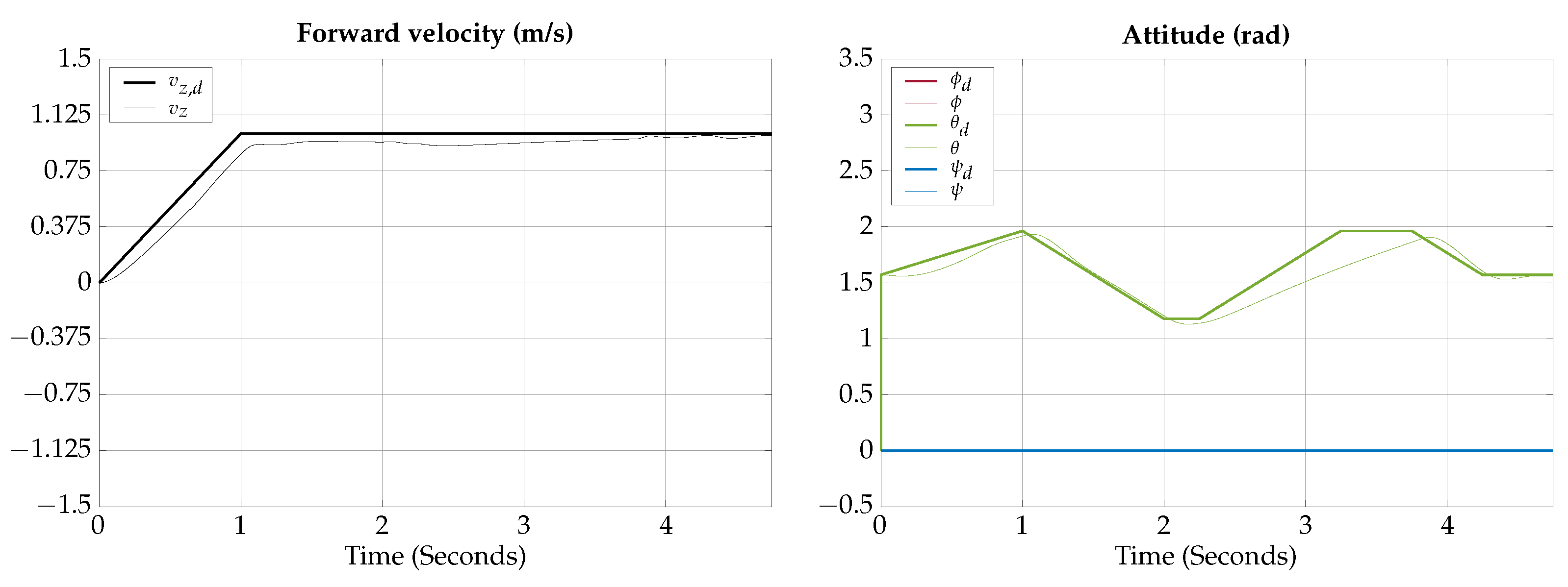
4.1.3. Test 3: Vertical Gliding
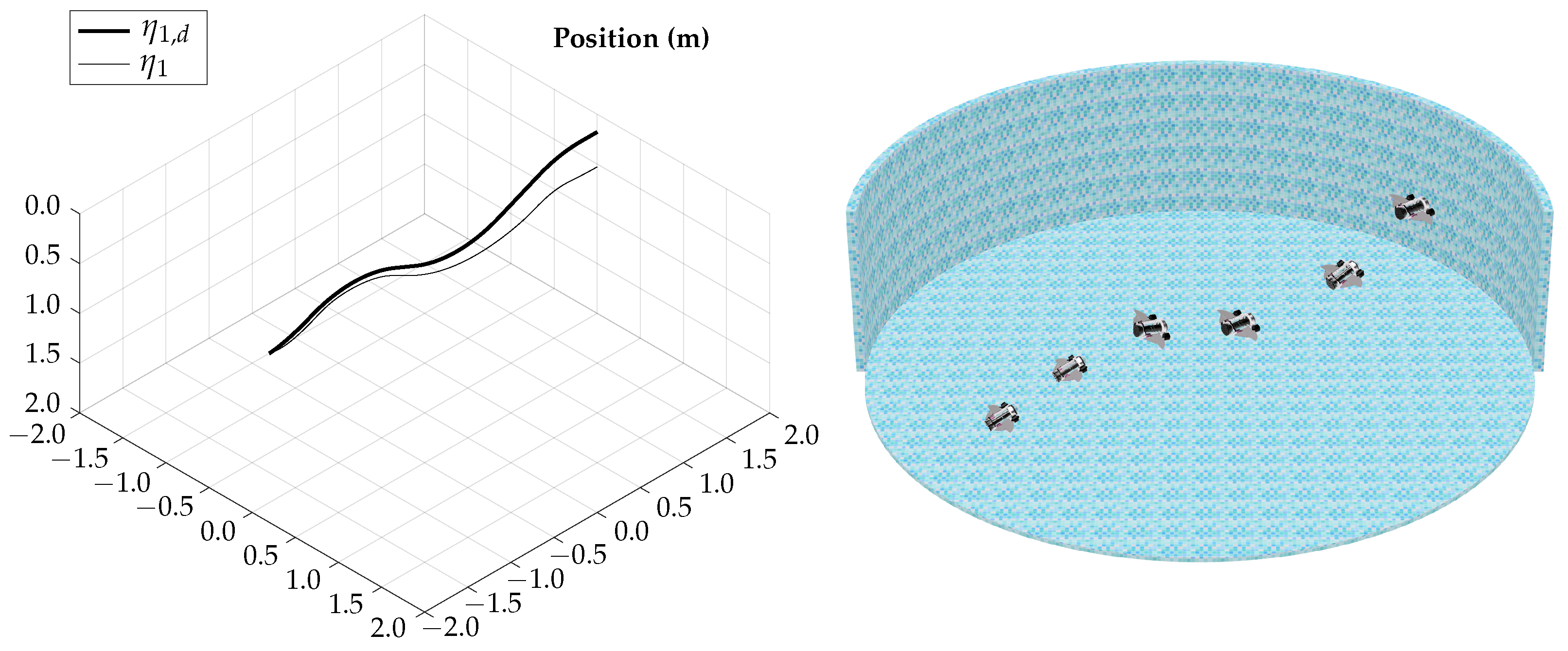
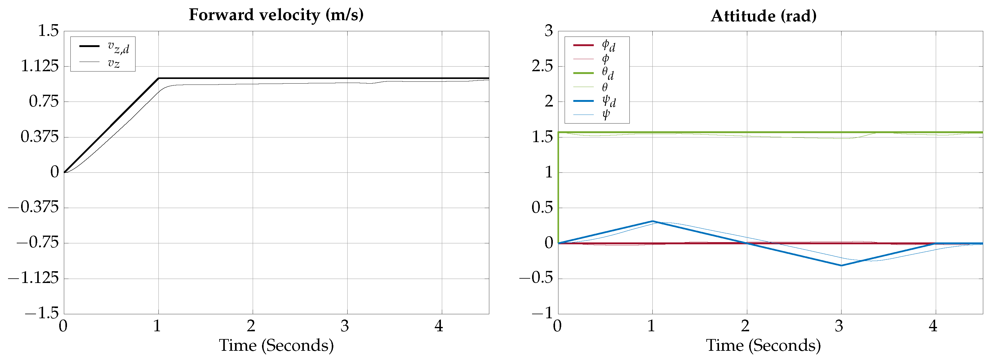
4.1.4. Test 4: Horizontal Axial Roll
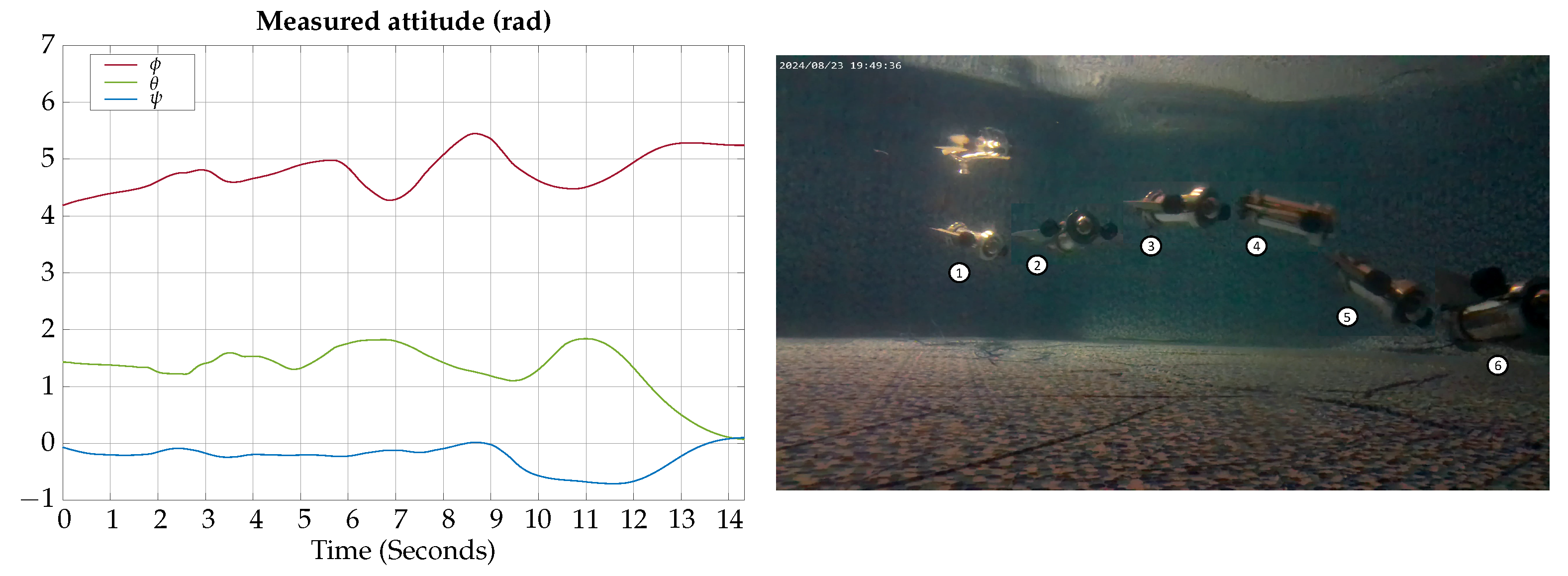
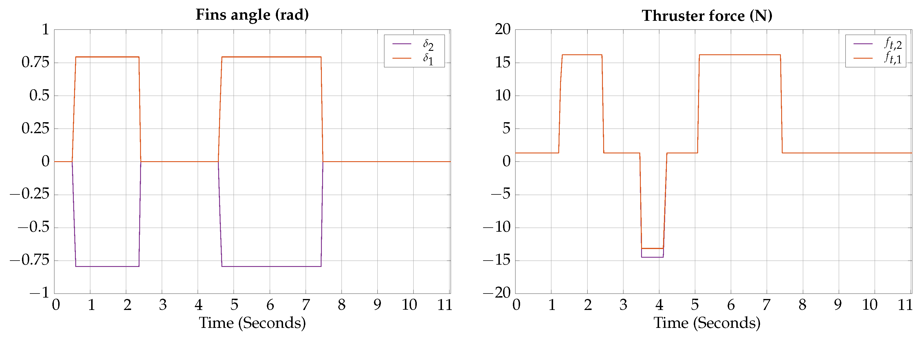
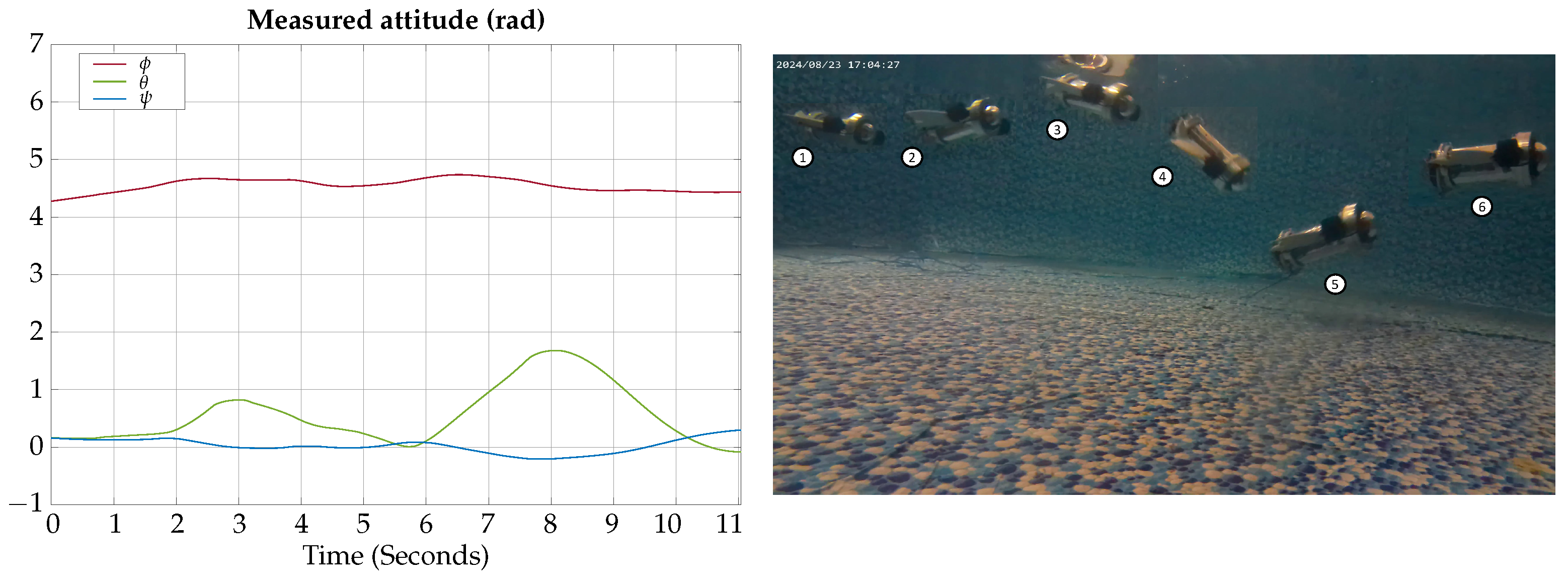
4.2. Experimental Results
4.2.1. Test 1: Vertical Submerging and Emerging
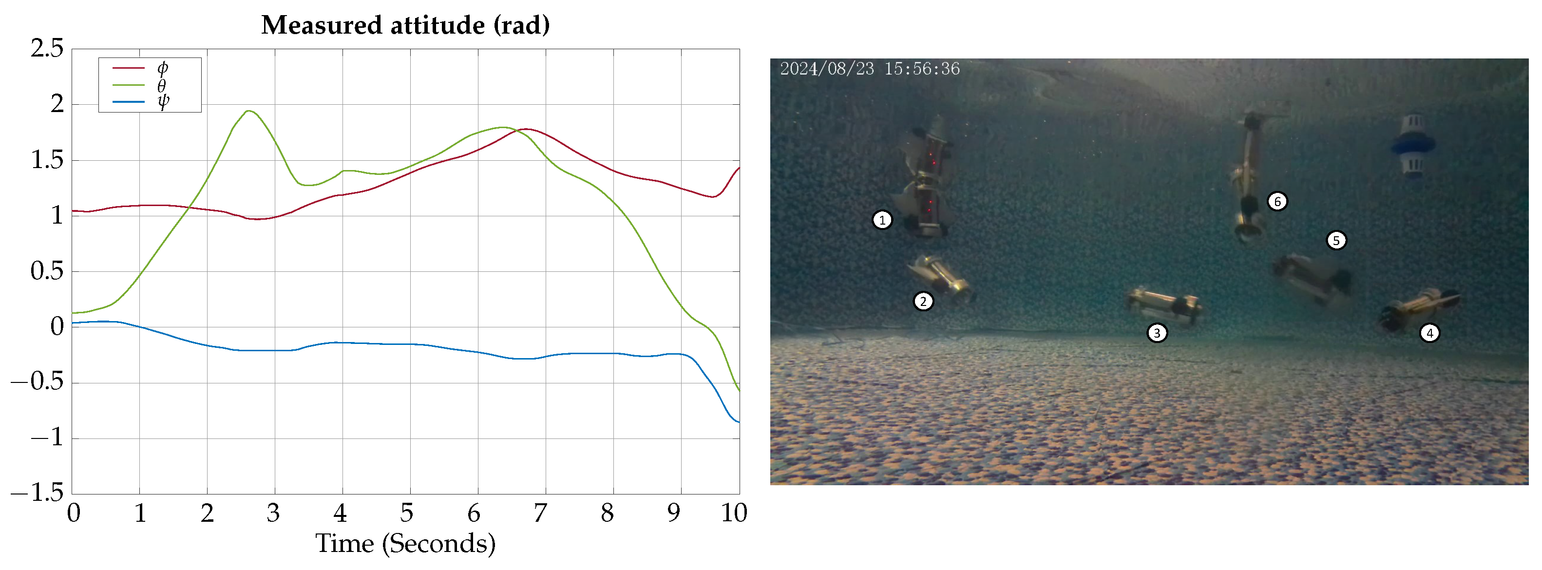
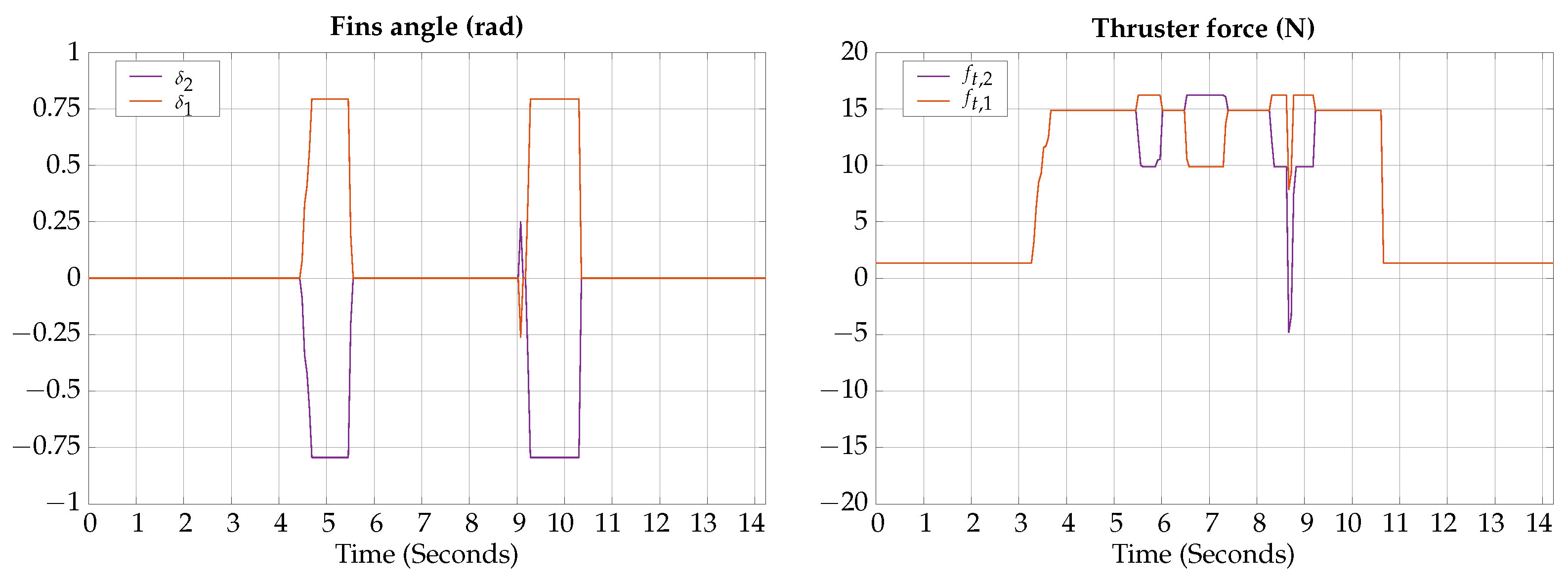
4.2.2. Test 2: Horizontal Gliding
4.2.3. Test 3: Vertical Gliding
5. Discussion
Author Contributions
Funding
Data Availability Statement
Conflicts of Interest
References
- Yu, X.; Tao, J.; Berilla, J. A bio-inspired flow sensor. In Nanosensors, Biosensors, and Info-Tech Sensors and Systems 2010; Varadan, V.K., Ed.; SPIE: St Bellingham, WA, USA, 2010. [Google Scholar]
- Valdivia y Alvarado, P.; Subramaniam, V.; Triantafyllou, M. Design of a bio-inspired whisker sensor for underwater applications. In Proceedings of the SENSORS, 2012 IEEE, Taipei, Taiwan, 28–31 October 2012; pp. 1–4. [Google Scholar] [CrossRef]
- Xu, P.; Liu, J.; Liu, X.; Wang, X.; Zheng, J.; Wang, S.; Chen, T.; Wang, H.; Wang, C.; Fu, X.; et al. A bio-inspired and self-powered triboelectric tactile sensor for underwater vehicle perception. Npj Flex. Electron. 2022, 6, 25. [Google Scholar] [CrossRef]
- Sun, B.; Li, W.; Wang, Z.; Zhu, Y.; He, Q.; Guan, X.; Dai, G.; Yuan, D.; Li, A.; Cui, W.; et al. Recent Progress in Modeling and Control of Bio-Inspired Fish Robots. J. Mar. Sci. Eng. 2022, 10, 773. [Google Scholar] [CrossRef]
- Manduca, G.; Santaera, G.; Miraglia, M.; Jansen Van Vuuren, G.; Dario, P.; Stefanini, C.; Romano, D. A bioinspired control strategy ensures maneuverability and adaptability for dynamic environments in an underactuated robotic fish. J. Intell. Robot. Syst. 2024, 110, 69. [Google Scholar] [CrossRef]
- Heinen, Y.; Tanev, I.; Kimura, T. The Effect of a Limited Underactuated Posterior Joint on the Speed and Energy Efficiency of a Fish Robot. Appl. Sci. 2024, 14, 5010. [Google Scholar] [CrossRef]
- Luo, Y.; Xiao, Q.; Zhu, Q.; Pan, G. Pulsed-jet propulsion of a squid-inspired swimmer at high Reynolds number. Phys. Fluids 2020, 32, 111901. [Google Scholar] [CrossRef]
- Bianchi, G.; Lanzetti, L.; Mariana, D.; Cinquemani, S. Bioinspired design and experimental validation of an aquatic snake robot. Biomimetics 2024, 9, 87. [Google Scholar] [CrossRef]
- Zhang, J.; Chen, Y.; Liu, Y.; Gong, Y. Dynamic modeling of underwater snake robot by hybrid rigid-soft actuation. J. Mar. Sci. Eng. 2022, 10, 1914. [Google Scholar] [CrossRef]
- Yang, Y.; Chu, C.; Jin, H.; Hu, Q.; Xu, M.; Dong, E. Design, modeling, and control of an Aurelia-inspired robot based on SMA artificial muscles. Biomimetics 2023, 8, 261. [Google Scholar] [CrossRef]
- Muralidharan, M.; Saini, P.; Ameta, P.; Palani, I.A. Bio-inspired soft jellyfish robot: A novel polyimide-based structure actuated by shape memory alloy. Int. J. Intell. Robot. Appl. 2023, 7, 671–682. [Google Scholar] [CrossRef]
- Soliman, M.; Mousa, M.A.; Saleh, M.A.; Elsamanty, M.; Radwan, A.G. Modelling and implementation of soft bio-mimetic turtle using echo state network and soft pneumatic actuators. Sci. Rep. 2021, 11, 12076. [Google Scholar] [CrossRef]
- van der Geest, N.; Garcia, L.; Borret, F.; Nates, R.; Gonzalez, A. Soft-robotic green sea turtle (Chelonia mydas) developed to replace animal experimentation provides new insight into their propulsive strategies. Sci. Rep. 2023, 13, 11983. [Google Scholar] [CrossRef] [PubMed]
- Zhang, Y.; Wang, S.; Wang, X.; Geng, Y. Design and control of bionic manta ray robot with flexible pectoral fin. In Proceedings of the 2018 IEEE 14th International Conference on Control and Automation (ICCA), Anchorage, AK, USA, 12–15 June 2018. [Google Scholar]
- Bianchi, G.; Maffi, L.; Tealdi, M.; Cinquemani, S. A bioinspired cownose ray robot for seabed exploration. Biomimetics 2023, 8, 30. [Google Scholar] [CrossRef] [PubMed]
- Hao, Y.; Cao, Y.; Cao, Y.; Huang, Q.; Pan, G. Course Control of a Manta Robot Based on Amplitude and Phase Differences. J. Mar. Sci. Eng. 2022, 10, 285. [Google Scholar] [CrossRef]
- Li, Z.; Chao, X.; Hameed, I.; Li, J.; Zhao, W.; Jing, X. Biomimetic omnidirectional multi-tail underwater robot. Mech. Syst. Signal Process. 2022, 173, 109056. [Google Scholar] [CrossRef]
- Fish, F.E. Advantages of aquatic animals as models for bio-inspired drones over present AUV technology. Bioinspir. Biomim. 2020, 15, 025001. [Google Scholar] [CrossRef]
- Murphy, A.J.; Haroutunian, M. Using bio-inspiration to improve capabilities of underwater vehicles. In Proceedings of the 17th International Symposium on Unmanned Untethered Submersible Technology (UUST), Portsmouth, NH, USA, 21–24 August 2011; Newcastle University: Newcastle upon Tyne, UK, 2011. [Google Scholar]
- Fish, F.E. Biomechanics and energetics in aquatic and semiaquatic mammals: Platypus to whale. Physiol. Biochem. Zool. 2000, 73, 683–698. [Google Scholar] [CrossRef]
- Scaradozzi, D.; Palmieri, G.; Costa, D.; Pinelli, A. BCF swimming locomotion for autonomous underwater robots: A review and a novel solution to improve control and efficiency. Ocean Eng. 2017, 130, 437–453. [Google Scholar] [CrossRef]
- Mitin, I.; Korotaev, R.; Ermolaev, A.; Mironov, V.; Lobov, S.A.; Kazantsev, V.B. Bioinspired Propulsion System for a Thunniform Robotic Fish. Biomimetics 2022, 7, 215. [Google Scholar] [CrossRef]
- Zhou, J.; Si, Y.; Chen, Y. A review of subsea AUV technology. J. Mar. Sci. Eng. 2023, 11, 1119. [Google Scholar] [CrossRef]
- Webb, P.W. Maneuverability—General issues. IEEE J. Ocean. Eng. 2004, 29, 547–555. [Google Scholar] [CrossRef]
- Walker, J.A. Does a rigid body limit maneuverability? J. Exp. Biol. 2000, 203, 3391–3396. [Google Scholar] [CrossRef] [PubMed]
- He, J.; Cao, Y.; Huang, Q.; Cao, Y.; Tu, C.; Pan, G. A New Type of Bionic Manta Ray Robot. In Proceedings of the Global Oceans 2020: Singapore—U.S. Gulf Coast, Biloxi, MS, USA, 5–30 October 2020. [Google Scholar] [CrossRef]
- Huang, H.; Sheng, C.; Wu, J.; Wu, G.; Zhou, C.; Wang, H. Hydrodynamic analysis and motion simulation of fin and propeller driven manta ray robot. Appl. Ocean Res. 2021, 108, 102528. [Google Scholar] [CrossRef]
- Raj, A.; Thakur, A. Fish-inspired robots: Design, sensing, actuation, and autonomy—A review of research. Bioinspir. Biomim. 2016, 11, 031001. [Google Scholar] [CrossRef] [PubMed]
- Niu, C.; Zhang, L.; Bi, S.; Cai, Y. Development and depth control of a robotic fish mimicking cownose ray. In Proceedings of the 2012 IEEE International Conference on Robotics and Biomimetics (ROBIO), Guangzhou, China, 11–14 December 2012. [Google Scholar]
- Wang, J.; Liu, Q.; Cheng, H.; Fang, B.; Zhang, J.; Hong, J. Design, fabrication and experiment of a bionic manta ray robot fish. In Proceedings of the 2022 IEEE International Conference on Robotics and Biomimetics (ROBIO), Jinghong, China, 5–9 December 2022. [Google Scholar]
- Cai, Y.; Bi, S.; Li, G.; Hildre, H.P.; Zhang, H. From natural complexity to biomimetic simplification: The realization of bionic fish inspired by the cownose ray. IEEE Robot. Autom. Mag. 2018, 26, 27–38. [Google Scholar] [CrossRef]
- Salazar, R.; Fuentes, V.; Abdelkefi, A. Classification of biological and bioinspired aquatic systems: A review. Ocean Eng. 2018, 148, 75–114. [Google Scholar] [CrossRef]
- León-González, G.; Núñez-Cruz, R.S.; Antonio-Yañez, E.D.; Herrera-Vidal, J.; Canales-Gómez, G.; Rueda-Germán, C. A Unified Approach to Modeling and Simulation of Underwater Vehicle Multi-Manipulator Systems. Machines 2024, 12, 94. [Google Scholar] [CrossRef]
- Barbalata, C. Modelling and Control of Lightweight Underwater Vehicle-Manipulator Systems. Ph.D. Thesis, Heriot-Watt University, Edinburgh, Scotland, 2017. [Google Scholar]
- Fossen, T.I. Handbook of Marine Craft Hydrodynamics and Motion Control; John Wiley & Sons: Hoboken, NJ, USA, 2021. [Google Scholar]
- Antonelli, G. Underwater Robots: Motion and Force Control of Vehicle-Manipulator Systems (Volume 2); Springer: Berlin/Heidelberg, Germany, 2006. [Google Scholar]
- Schjølberg, I.; Fossen, T. Modelling and control of underwater vehicle-manipulator systems. In Proceedings of the 3rd Conference on Marine Craft Maneuvering and Control (MCMC), Southampton, UK, 7–9 September 1994; pp. 45–57. [Google Scholar]
- Bani Younes, A.; Turner, J.; Mortari, D.; Junkins, J. A Survey of Attitude Error Representations. In Proceedings of the AIAA/AAS Astrodynamics Specialist Conference 2012, Minneapolis, MN, USA, 13–16 August 2012. [Google Scholar] [CrossRef]
- Jung, Y.; Cho, S.; Shim, D. A Comprehensive Flight Control Design and Experiment of a Tail-Sitter UAV. In Proceedings of the AIAA Guidance, Navigation, and Control (GNC) Conference, Chicago, IL, USA, 10–13 August 2013. [Google Scholar] [CrossRef]
- Paschal, T.; Shintake, J.; Mintchev, S.; Floreano, D. Development of bio-inspired underwater robot with adaptive morphology capable of multiple swimming modes. In Proceedings of the 2017 IEEE/RSJ International Conference on Intelligent Robots and Systems (IROS), Vancouver, BC, Canada, 24–28 September 2017. [Google Scholar]
- Nguyen, D.Q.; Ho, V.A. Anguilliform Swimming Performance of an Eel-Inspired Soft Robot. Soft Robot. 2022, 9, 425–439. [Google Scholar] [CrossRef]
- Vercruyssen, T.G.A.; Henrion, S.; Müller, U.K.; van Leeuwen, J.L.; van der Helm, F.C.T. Cost of Transport of Undulating Fin Propulsion. Biomimetics 2023, 8, 214. [Google Scholar] [CrossRef]
- Berlinger, F.; Saadat, M.; Haj-Hariri, H.; Lauder, G.V.; Nagpal, R. Fish-like three-dimensional swimming with an autonomous, multi-fin, and biomimetic robot. Bioinspir. Biomim. 2021, 16, 026018. [Google Scholar] [CrossRef]
- Lu, B.; Zhou, C.; Wang, J.; Zhang, Z.; Tan, M. Toward Swimming Speed Optimization of a Multi-Flexible Robotic Fish With Low Cost of Transport. IEEE Trans. Autom. Sci. Eng. 2024, 21, 2804–2815. [Google Scholar] [CrossRef]
- Hall, R.; Onal, C.D. Untethered Underwater Soft Robot with Thrust Vectoring. In Proceedings of the 2024 IEEE International Conference on Robotics and Automation (ICRA), Yokohama, Japan, 13–17 May 2024; pp. 8828–8834. [Google Scholar] [CrossRef]
- Tong, R.; Wu, Z.; Chen, D.; Wang, J.; Du, S.; Tan, M.; Yu, J. Design and Optimization of an Untethered High-Performance Robotic Tuna. IEEE/ASME Trans. Mechatronics 2022, 27, 4132–4142. [Google Scholar] [CrossRef]
- White, C.H.; Lauder, G.V.; Bart-Smith, H. Tunabot Flex: A tuna-inspired robot with body flexibility improves high-performance swimming. Bioinspir. Biomim. 2021, 16, 026019. [Google Scholar] [CrossRef] [PubMed]
- Yang, S.B.; Qiu, J.; Han, X.Y. Kinematics Modeling and Experiments of Pectoral Oscillation Propulsion Robotic Fish. J. Bionic Eng. 2009, 6, 174–179. [Google Scholar] [CrossRef]
- Cao, Y.; Lu, Y.; Cai, Y.; Bi, S.; Pan, G. CPG-fuzzy-based control of a cownose-ray-like fish robot. Ind. Robot. Int. J. Robot. Res. Appl. 2019, 46, 779–791. [Google Scholar] [CrossRef]
- Ma, H.; Cai, Y.; Wang, Y.; Bi, S.; Gong, Z. A biomimetic cownose ray robot fish with oscillating and chordwise twisting flexible pectoral fins. Ind. Robot. Int. J. 2015, 42, 214–221. [Google Scholar] [CrossRef]
- Ji, Y.; Wei, Y.; Liu, J.; An, D. Design and Realization of a Novel Hybrid-Drive Robotic Fish for Aquaculture Water Quality Monitoring. J. Bionic Eng. 2022, 20, 543–557. [Google Scholar] [CrossRef]
- Zhang, L.; Niu, C.; Bi, S.; Cai, Y. Kinematic model analysis and design optimization of a bionic pectoral fins. In Proceedings of the 2013 IEEE International Conference on Robotics and Biomimetics (ROBIO), Shenzhen, China, 12–14 December 2013; Volume 32, pp. 2219–2224. [Google Scholar] [CrossRef]
- Niu, C.; Zhang, L.; Bi, S.; Cai, Y. Mechanical design and implementation of a bio-inspired robotic fish with flapping foils. In Proceedings of the 2013 IEEE International Conference on Robotics and Biomimetics (ROBIO), Shenzhen, China, 12–14 December 2013; Volume 204, pp. 2291–2296. [Google Scholar] [CrossRef]
- Chen, L.; Bi, S.; Cai, Y.; Cao, Y.; Pan, G. Design and Experimental Research on a Bionic Robot Fish with Tri-Dimensional Soft Pectoral Fins Inspired by Cownose Ray. J. Mar. Sci. Eng. 2022, 10, 537. [Google Scholar] [CrossRef]


| (kg) | (kg m2) | (m) | (m) |
|---|---|---|---|
| 3.956 |
| (kg) | (kg m2) | (m) | (Ns/m) | (Nms/rad) |
|---|---|---|---|---|
| 4.3 |
| T | ||||
|---|---|---|---|---|
| (s) | (m/s) | (rad) | (rad) | (rad) |
| 0 | 0 | 0 | 0 | 0 |
| 0.5 | 0.5 | 0 | 0 | 0 |
| 2 | 1 | 0 | /2 | 0 |
| 3 | 0.5 | 0 | /2 | 0 |
| 1 | 0.25 | 0 | /4 | 0 |
| 2 | −1 | 0 | 0 | 0 |
| 0.5 | 0 | 0 | 0 | 0 |
| T | ||||
|---|---|---|---|---|
| (s) | (m/s) | (rad) | (rad) | (rad) |
| 0 | 0 | 0 | /2 | 0 |
| 1 | 1 | −/4 | /2 | 0 |
| 1 | 1 | /4 | /2 | 0 |
| 0.75 | 1 | /4 | /2 | 0 |
| 1 | 1 | −/4 | /2 | 0 |
| 0.25 | 1 | −/4 | /2 | 0 |
| 0.25 | 0.5 | 0 | /2 | 0 |
| 1 | 0.5 | 0 | /2 | 0 |
| T | ||||
|---|---|---|---|---|
| (s) | (m/s) | (rad) | (rad) | (rad) |
| 0 | 0 | 0 | /2 | 0 |
| 1 | 1 | 0 | 5/8 | 0 |
| 1 | 1 | 0 | 3/8 | 0 |
| 0.25 | 1 | 0 | 3/8 | 0 |
| 1 | 1 | 0 | 5/8 | 0 |
| 0.5 | 1 | 0 | 5/2 | 0 |
| 0.5 | 1 | 0 | /2 | 0 |
| 0.5 | 1 | 0 | /2 | 0 |
| T | ||||
|---|---|---|---|---|
| (s) | (m/s) | (rad) | (rad) | (rad) |
| 0 | 0 | 0 | /2 | 0 |
| 1 | 1 | 0 | /2 | /10 |
| 2 | 1 | 0 | /2 | /10 |
| 1 | 1 | 0 | /2 | 0 |
| 0.5 | 1 | 0 | /2 | 0 |
Disclaimer/Publisher’s Note: The statements, opinions and data contained in all publications are solely those of the individual author(s) and contributor(s) and not of MDPI and/or the editor(s). MDPI and/or the editor(s) disclaim responsibility for any injury to people or property resulting from any ideas, methods, instructions or products referred to in the content. |
© 2024 by the authors. Licensee MDPI, Basel, Switzerland. This article is an open access article distributed under the terms and conditions of the Creative Commons Attribution (CC BY) license (https://creativecommons.org/licenses/by/4.0/).
Share and Cite
Mar-Castro, E.; May-Rodríguez, S.A.; Núñez-Cruz, R.S.; Antonio-Yañez, E.D.; Aparicio-Lastiri, L.M.; Herrera-Vidal, J. Development of a Vertical Submerging and Emerging Bat-Ray-Inspired Underwater Vehicle. Biomimetics 2024, 9, 582. https://doi.org/10.3390/biomimetics9100582
Mar-Castro E, May-Rodríguez SA, Núñez-Cruz RS, Antonio-Yañez ED, Aparicio-Lastiri LM, Herrera-Vidal J. Development of a Vertical Submerging and Emerging Bat-Ray-Inspired Underwater Vehicle. Biomimetics. 2024; 9(10):582. https://doi.org/10.3390/biomimetics9100582
Chicago/Turabian StyleMar-Castro, Enrique, Sergio Alejandro May-Rodríguez, Rafael Stanley Núñez-Cruz, Elba Dolores Antonio-Yañez, Luis Mario Aparicio-Lastiri, and Juan Herrera-Vidal. 2024. "Development of a Vertical Submerging and Emerging Bat-Ray-Inspired Underwater Vehicle" Biomimetics 9, no. 10: 582. https://doi.org/10.3390/biomimetics9100582
APA StyleMar-Castro, E., May-Rodríguez, S. A., Núñez-Cruz, R. S., Antonio-Yañez, E. D., Aparicio-Lastiri, L. M., & Herrera-Vidal, J. (2024). Development of a Vertical Submerging and Emerging Bat-Ray-Inspired Underwater Vehicle. Biomimetics, 9(10), 582. https://doi.org/10.3390/biomimetics9100582