
Dimensioning of Biomimetic Beams under Bending for Additively Manufactured Structural Components


Abstract
1. Introduction
2. Methodology
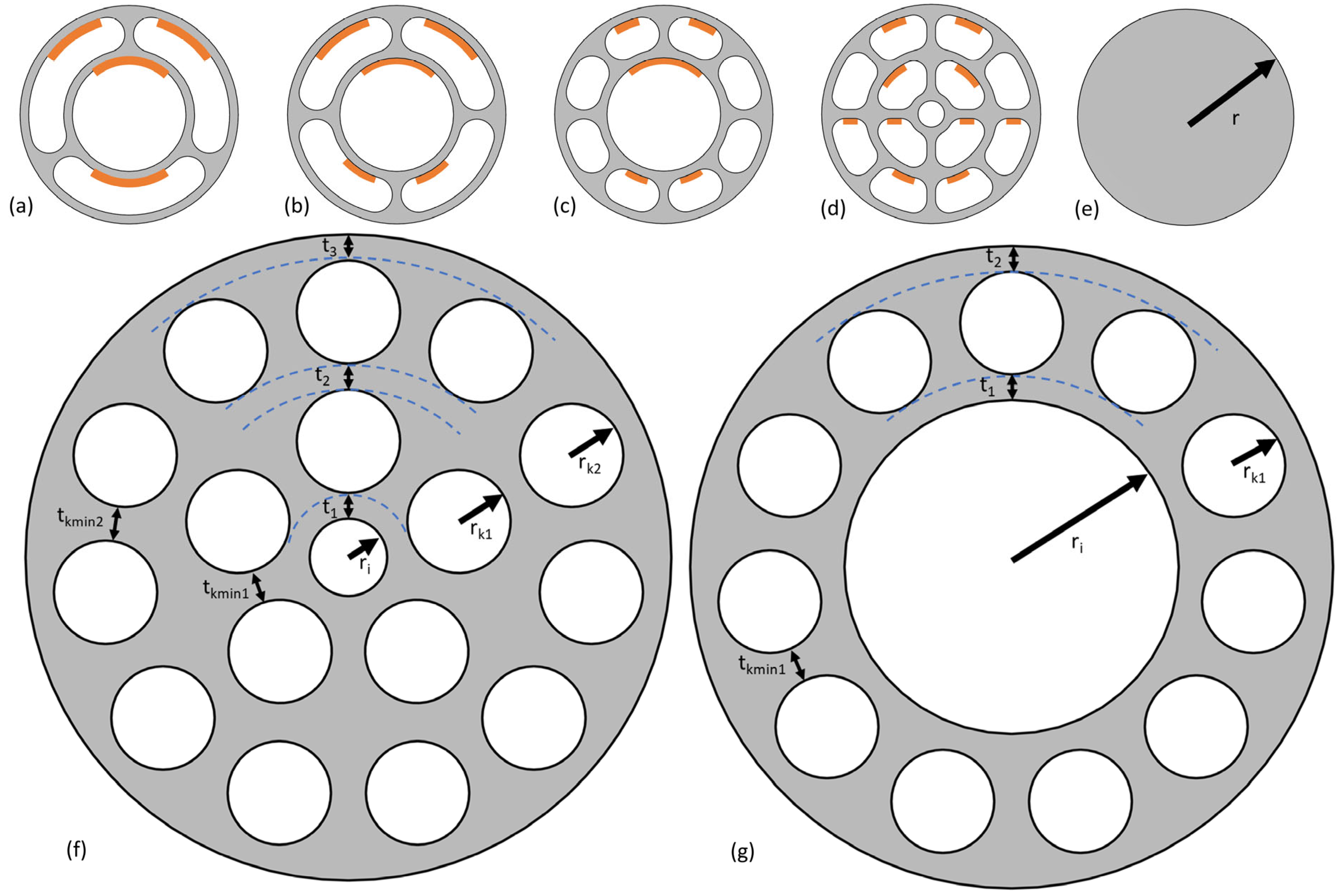
- Abstraction of a biological blueprint and generation of four beam cross-section designs
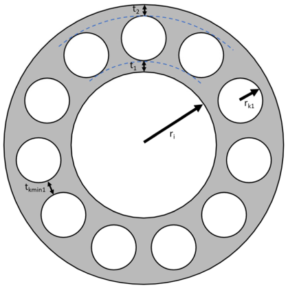
- Development of two abstractions and parametric models considering manufacturability by PBF-LB/M
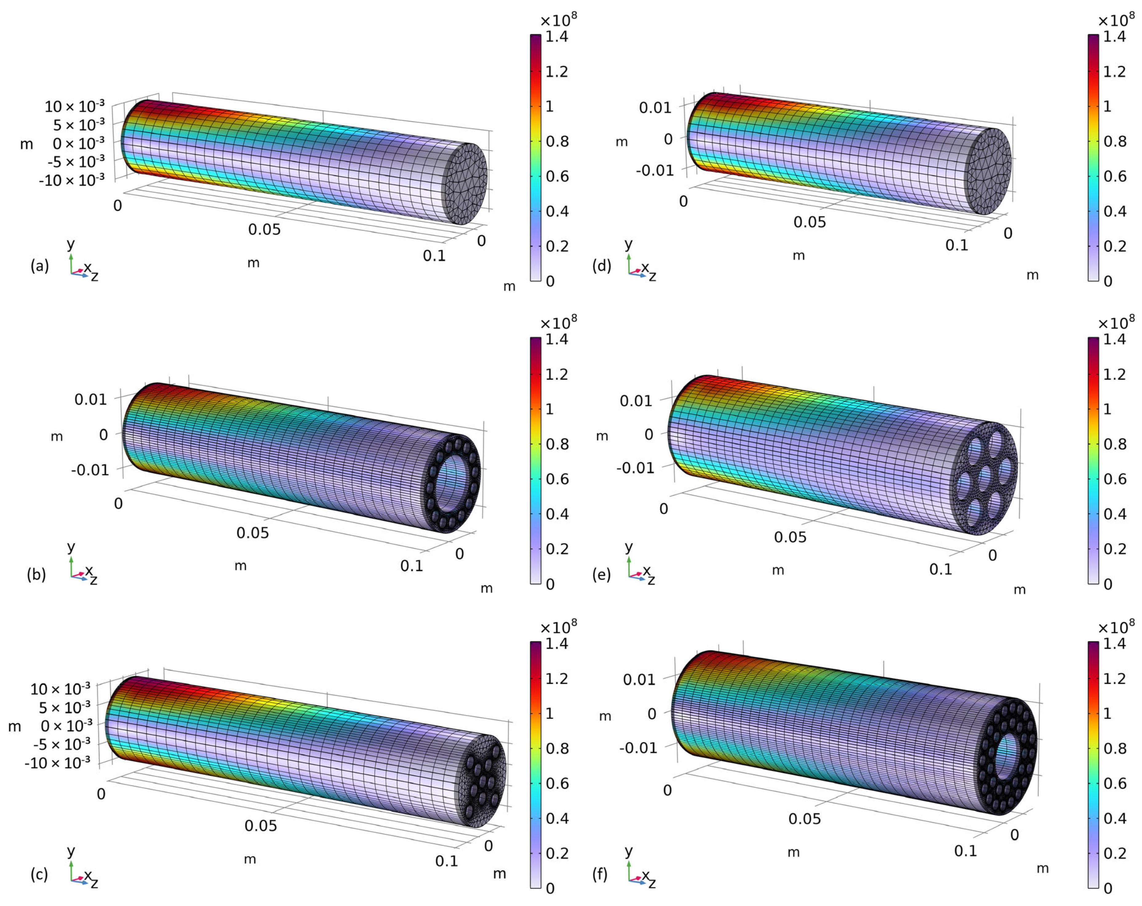
- Parametric optimization of two biomimetic beams under various bending loads
- Parametric optimization of a solid cylindrical beam under various bending loads as a reference
- Conduct of a mesh convergence study
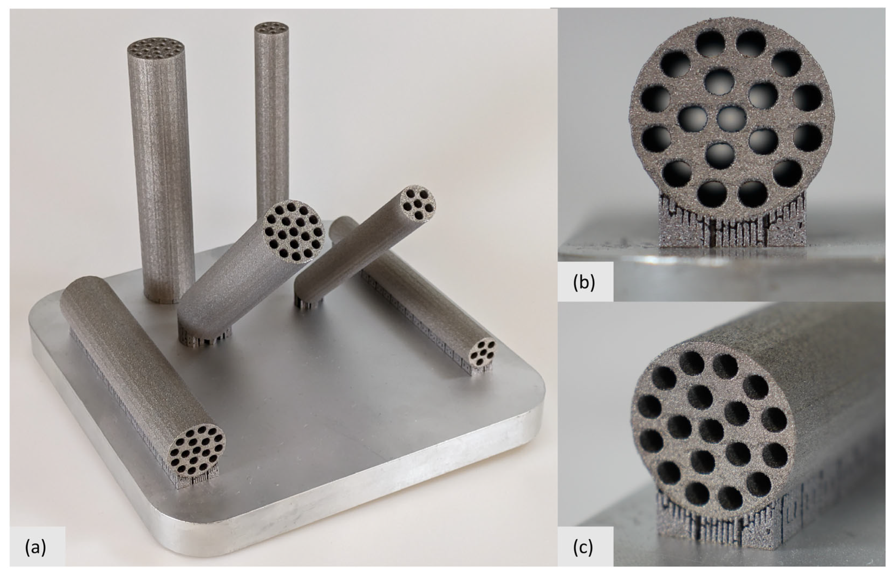
- Additive manufacturing of exemplary biomimetic beams
3. Abstraction and Parameter Optimization
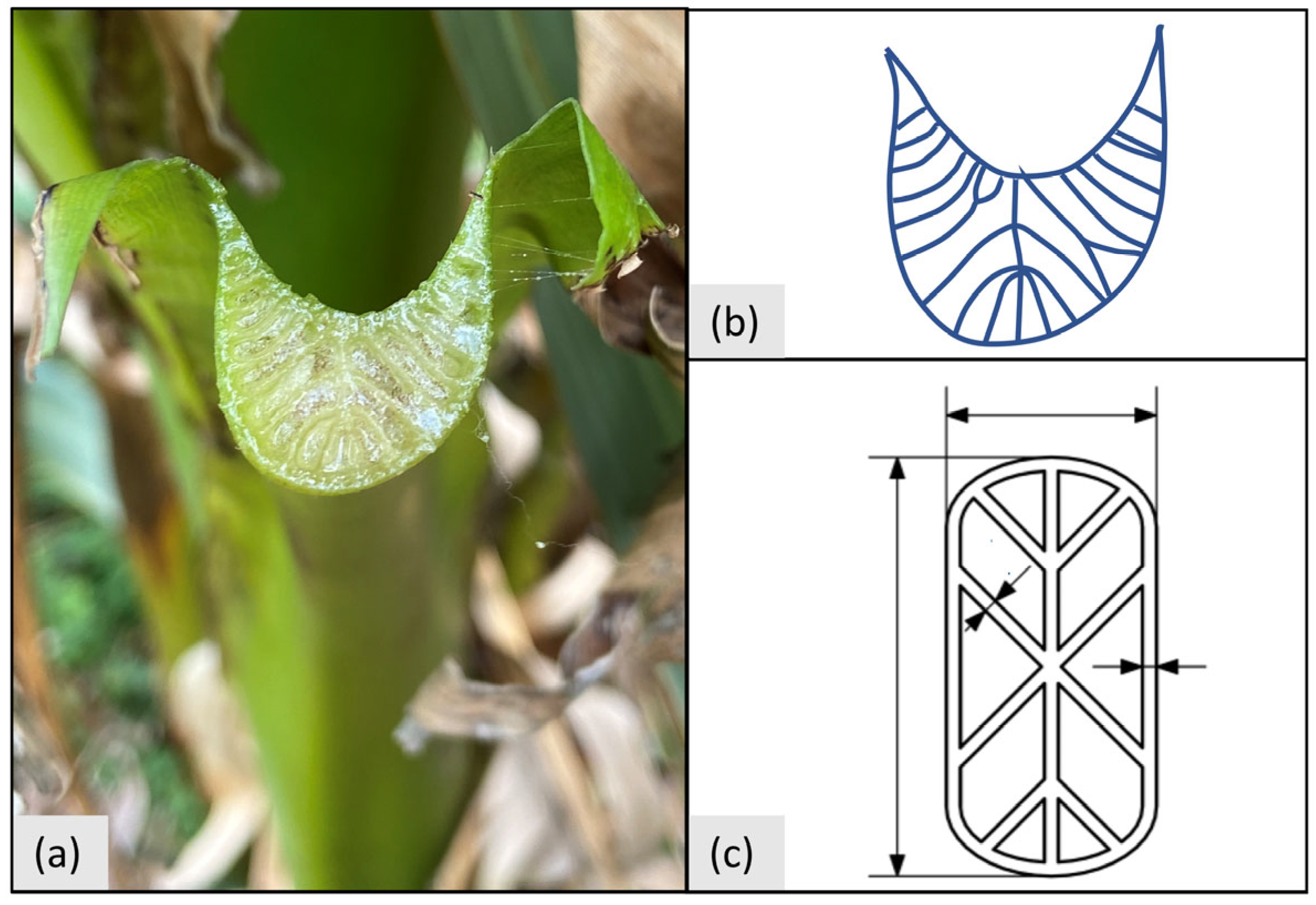
3.1. Biological Role Models
3.2. Abstraction of Banana Pseudo-Stem for Additive Manufacturing
3.3. Comparison Structure
3.4. Material
3.5. Parameter Optimization
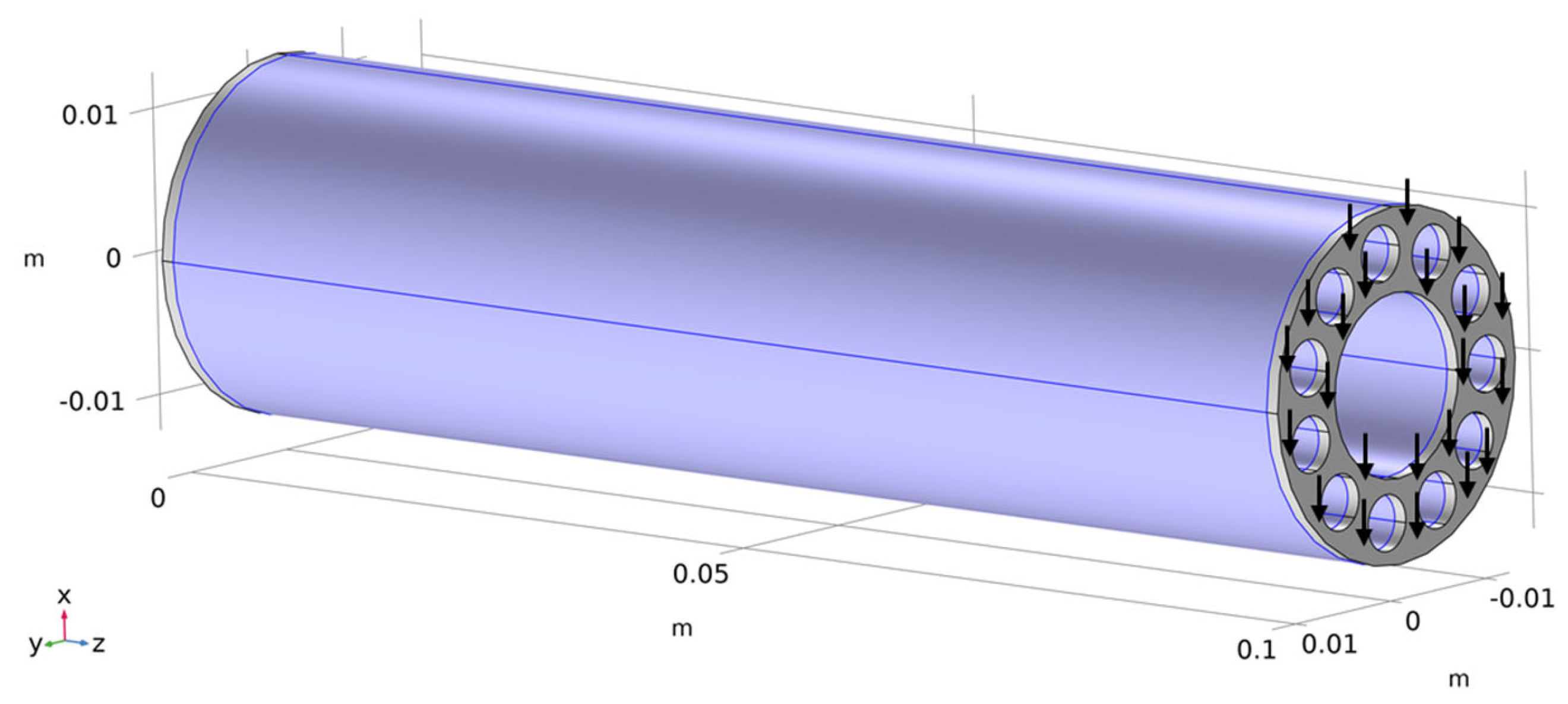
- Domain 1: 0 mm ≤ z < 1 mm
- Domain 2: 1 mm ≤ z ≤ 100 mm
- Domain 3: 100 mm < z ≤ 101 mm
3.6. Discretization
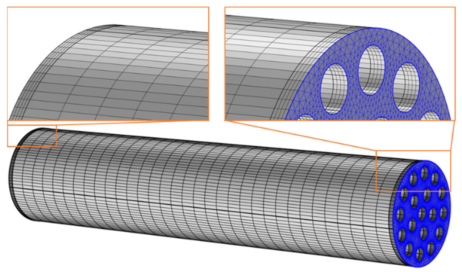
- Automatic meshing of the end surface using triangular elements (highlighted surface in Figure 4) based on five parameters for automatic meshing. The parameters were maximum element size, minimum element size, maximum element growth rate, curvature factor, and resolution of narrow regions.
- Development of prism elements based on triangular mesh on the surface and the swept function. The thickness of the prism elements in domains 1 and 3 was chosen to be 0.25 mm (4 layers). For the rest of the beam, the thickness of the prisms was chosen to be 3 mm (33 layers).
3.7. Mesh Convergence Study
4. Results
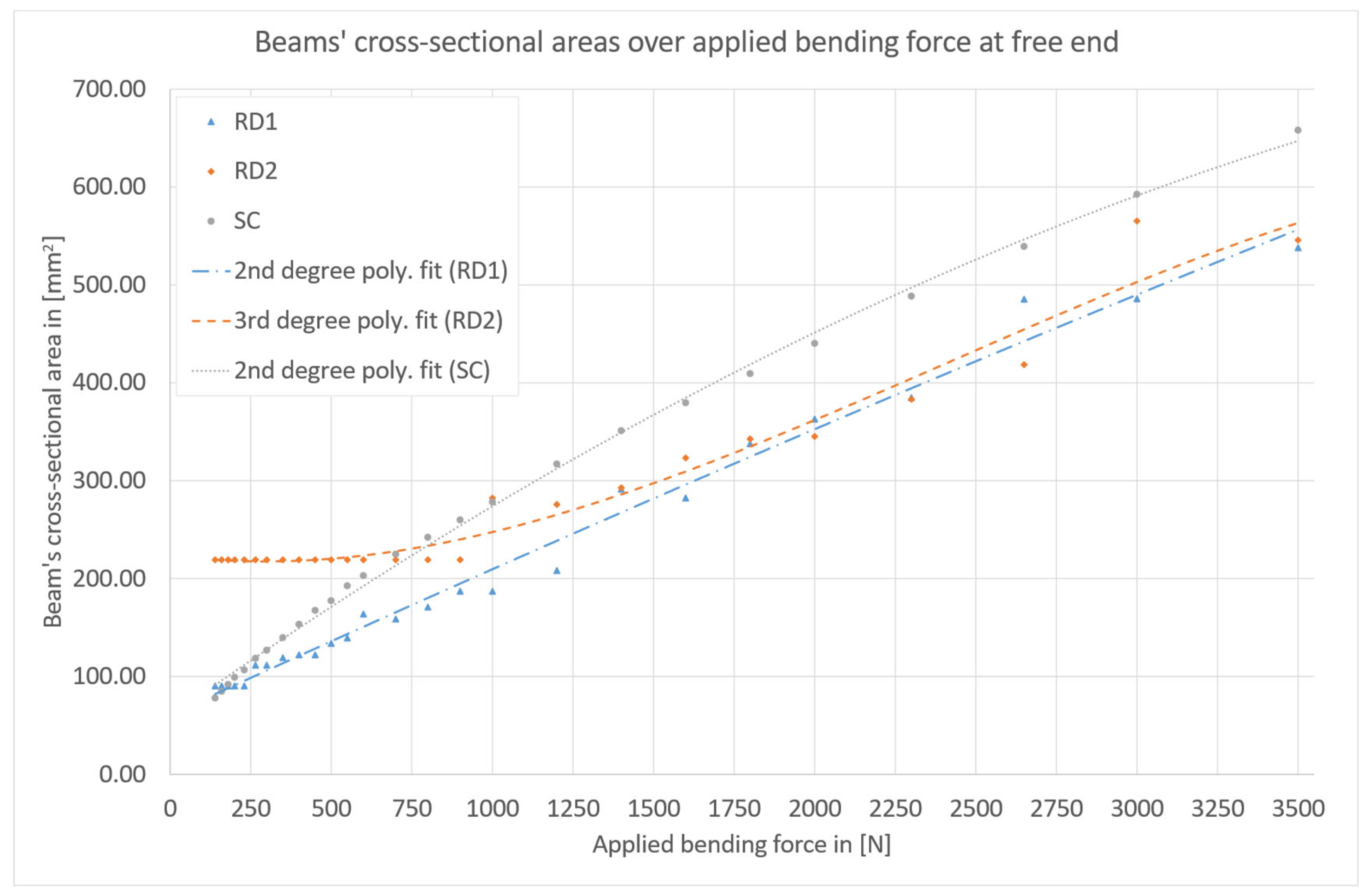
4.1. Numerical Results
4.2. Additive Manufacturing
5. Conclusions and Future Prospects
Supplementary Materials
Author Contributions
Funding
Institutional Review Board Statement
Data Availability Statement
Acknowledgments
Conflicts of Interest
Nomenclature
| A | Cross-sectional area of beam |
| C | Feasible set |
| L(u(ξ),ξ) = 0 | System of discretized partial differential equations |
| lB | Length of beams (constant), 100 mm |
| lbb | Lower bound of control variables |
| lbP | Lower bound of performance constraint |
| lbΨ | Lower bound of general expressions of the control variables |
| NPL,D1,3 | Number of prism element layers in domains 1 and 3 (meshing) |
| NPL,D2 | Number of prism element layers in domain 2 (meshing) |
| P(u(ξ),ξ) | Performance constraints |
| Q | Scalar-valued objective function |
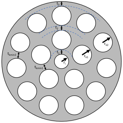
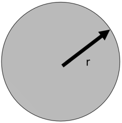
| r | Radius |
| ri | Inner radius |
| rk1 | Radius of cavities in first cavity ring |
| rk2 | Radius of cavities in second cavity ring |
| ro | Outer radius |
| Sel,max | Maximum element size (meshing) |
| Sel,min | Minimum element size (meshing) |
| tkmin1 | Minimum distance between cavities in first cavity ring |
| tkmin2 | Minimum distance between cavities in second cavity ring |
| t1 | Wall thickness of first ring |
| t2 | Wall thickness of second ring |
| t3 | Wall thickness of third ring |
| u | PDE solution |
| ubb | Lower bound of control variables |
| ubP | Upper bound of performance constraint |
| ubΨ | Upper bound of general expressions of the control variables |
| xP1 | Arbitrary design parameter P1 |
| xP2 | Arbitrary design parameter P2 |
| xPn | Arbitrary design parameter PN |
| ξ | Control variables |
| σmax | Maximum allowable von Mises stress |
| Ψ(ξ) | General expressions of the control variables |
| …RD1 | Subscript indicating reference to revolver drum beam 1 |
| …RD2 | Subscript indicating reference to revolver drum beam 2 |
| …SC | Subscript indicating reference to solid cylindrical beam |
Appendix A

| Revolver drum 1 (RD1) | Model parameters | ||||||||||||
| Young’s modulus | Poisson’s ratio | Density | Length | ||||||||||
| 57 [GPa] | 0.34 | 2.67 [g/cm3] | 100 [mm] | ||||||||||
 | Design variables | ||||||||||||
| Parameter | Variable | Minimum | Maximum | ||||||||||
| Inner radius | ri | 1.5 [mm] | 7.5 [mm] | ||||||||||
| Wall thickness first ring | t1 | 1 [mm] | 9.5 [mm] | ||||||||||
| Wall thickness second ring | t2 | 1 [mm] | 9.5 [mm] | ||||||||||
| Radius of cavities in cavity ring | rk1 | 1.5 [mm] | 7.5 [mm] | ||||||||||
| Minimum distance between cavities in cavity ring | tkmin1 | 1.0 [mm] | 2 × (ri + t1) | ||||||||||
| Constraints | |||||||||||||
| Physical constraint | Numerical constraint | Minimum | Maximum | ||||||||||
| Yield strength of AlSi10Mg | Maximum von Mises stress in domain 2 | - | 141 [MPa] | ||||||||||
| Maximum diameter of 30 mm of beam | ri + t1 + t2 + 2 × rk1 | - | 15 [mm] | ||||||||||
| Bending | |||||||||||||
| Force [N] | Max. Bending Moment [Nm] | ri [mm] | t1 [mm] | t2 [mm] | rk1 [mm] | tkmin1 [mm] | Area [mm2] | ||||||
| 140 | 14 | 1.5000 | 1.0000 | 1.0000 | 1.5000 | 1.0000 | 90.32 | ||||||
| 160 | 16 | 1.5000 | 1.0000 | 1.0000 | 1.5000 | 1.0000 | 90.32 | ||||||
| 180 | 18 | 1.5000 | 1.0000 | 1.0000 | 1.5000 | 1.0000 | 90.32 | ||||||
| 200 | 20 | 1.5000 | 1.0000 | 1.0000 | 1.5000 | 1.0000 | 90.32 | ||||||
| 230 | 23 | 1.5000 | 1.0000 | 1.0000 | 1.5000 | 1.0000 | 90.32 | ||||||
| 265 | 26.5 | 1.5000 | 1.0000 | 1.0000 | 1.5000 | 5.0000 | 111.53 | ||||||
| 300 | 30 | 1.5000 | 1.0000 | 1.0000 | 1.5000 | 5.0000 | 111.53 | ||||||
| 350 | 35 | 3.0936 | 1.0000 | 1.0000 | 1.5000 | 1.0000 | 119.18 | ||||||
| 400 | 40 | 3.1825 | 1.0000 | 1.0000 | 1.5000 | 1.0000 | 121.97 | ||||||
| 450 | 45 | 3.1825 | 1.0000 | 1.0000 | 1.5000 | 1.0000 | 121.97 | ||||||
| 500 | 50 | 3.7825 | 1.0000 | 1.0000 | 1.5000 | 1.0000 | 133.75 | ||||||
| 550 | 55 | 4.1825 | 1.0000 | 1.0000 | 1.5000 | 1.0000 | 139.25 | ||||||
| 600 | 60 | 5.1825 | 1.0000 | 1.0000 | 1.5000 | 1.0000 | 163.60 | ||||||
| 700 | 70 | 5.0255 | 1.0000 | 1.0000 | 1.5000 | 1.0000 | 158.66 | ||||||
| 800 | 80 | 5.6387 | 1.0000 | 1.0000 | 1.5000 | 1.0000 | 170.86 | ||||||
| 900 | 90 | 6.3787 | 1.0000 | 1.0000 | 1.5000 | 1.0000 | 187.04 | ||||||
| 1000 | 100 | 6.3784 | 1.0000 | 1.0000 | 1.5000 | 1.0000 | 187.03 | ||||||
| 1200 | 120 | 7.5000 | 1.0000 | 1.0000 | 1.5000 | 1.0000 | 208.13 | ||||||
| 1400 | 140 | 1.8643 | 3.4934 | 1.2866 | 2.9185 | 1.2589 | 291.18 | ||||||
| 1600 | 160 | 6.4023 | 1.2577 | 1.2781 | 1.9665 | 2.1404 | 282.34 | ||||||
| 1800 | 180 | 4.2807 | 2.0517 | 2.0384 | 2.2948 | 1.3703 | 337.77 | ||||||
| 2000 | 200 | 4.0351 | 2.1814 | 2.1598 | 2.7252 | 1.1168 | 362.80 | ||||||
| 2300 | 230 | 3.7896 | 1.9188 | 1.5913 | 3.9043 | 1.7545 | 384.65 | ||||||
| 2650 | 265 | 2.8336 | 2.9109 | 2.2365 | 3.0961 | 4.4002 | 485.41 | ||||||
| 3000 | 300 | 1.7899 | 2.1242 | 3.5810 | 3.8958 | 1.0000 | 485.67 | ||||||
| 3500 | 350 | 1.5000 | 1.0000 | 1.0000 | 7.5000 | 1.0000 | 537.99 | ||||||
| Revolver drum 2 (RD2) | Model parameters | |||||||||||||
| Young’s modulus | Poisson’s ratio | Density | Length | |||||||||||
| 57 [GPa] | 0.34 | 2.67 [g/cm3] | 100 [mm] | |||||||||||
 | Design variables | |||||||||||||
| Parameter | Variable | Minimum | Maximum | |||||||||||
| Inner radius | ri | 1.5 [mm] | 7.5 [mm] | |||||||||||
| Wall thickness first ring | t1 | 1 [mm] | 5.5 [mm] | |||||||||||
| Wall thickness second ring | t2 | 1 [mm] | 5.5 [mm] | |||||||||||
| Wall thickness third ring | t3 | 1 [mm] | 5.5 [mm] | |||||||||||
| Radius of cavities in first cavity ring | rk1 | 1.5 [mm] | 7.5 [mm] | |||||||||||
| Radius of cavities in second cavity ring | rk2 | 1.5 [mm] | 7.5 [mm] | |||||||||||
| Minimum distance between cavities in first cavity ring | tkmin1 | 1 [mm] | 2 × (ri + t1) | |||||||||||
| Minimum distance between cavities in second cavity ring | tkmin2 | 1 [mm] | 2 × (ri + t1 + 2 × rk1 + t2) | |||||||||||
| Constraints | ||||||||||||||
| Physical constraint | Numerical constraint | Minimum | Maximum | |||||||||||
| Yield strength of AlSi10Mg | Maximum von Mises stress in domain 2 | - | 141 [MPa] | |||||||||||
| Maximum diameter of 30 mm of beam | ri + t1 + t2 + t3 + 2 × rk1 + 2 × rk2 | - | 15 [mm] | |||||||||||
| Bending | ||||||||||||||
| Force [N] | Max. Bending Moment [Nm] | ri [mm] | t1 [mm] | t2 [mm] | t3 [mm] | rk1 [mm] | rk2 [mm] | tkmin1 [mm] | tkmin2 [mm] | Area [mm2] | ||||
| 140 | 14 | 1.5000 | 1.0000 | 1.0000 | 1.0000 | 1.5000 | 1.5000 | 1.0000 | 1.0000 | 219.13 | ||||
| 160 | 16 | 1.5000 | 1.0000 | 1.0000 | 1.0000 | 1.5000 | 1.5000 | 1.0000 | 1.0000 | 219.13 | ||||
| 180 | 18 | 1.5000 | 1.0000 | 1.0000 | 1.0000 | 1.5000 | 1.5000 | 1.0000 | 1.0000 | 219.13 | ||||
| 200 | 20 | 1.5000 | 1.0000 | 1.0000 | 1.0000 | 1.5000 | 1.5000 | 1.0000 | 1.0000 | 219.13 | ||||
| 230 | 23 | 1.5000 | 1.0000 | 1.0000 | 1.0000 | 1.5000 | 1.5000 | 1.0000 | 1.0000 | 219.13 | ||||
| 265 | 26.5 | 1.5000 | 1.0000 | 1.0000 | 1.0000 | 1.5000 | 1.5000 | 1.0000 | 1.0000 | 219.13 | ||||
| 300 | 30 | 1.5000 | 1.0000 | 1.0000 | 1.0000 | 1.5000 | 1.5000 | 1.0000 | 1.0000 | 219.13 | ||||
| 350 | 35 | 1.5000 | 1.0000 | 1.0000 | 1.0000 | 1.5000 | 1.5000 | 1.0000 | 1.0000 | 219.13 | ||||
| 400 | 40 | 1.5000 | 1.0000 | 1.0000 | 1.0000 | 1.5000 | 1.5000 | 1.0000 | 1.0000 | 219.13 | ||||
| 450 | 45 | 1.5000 | 1.0000 | 1.0000 | 1.0000 | 1.5000 | 1.5000 | 1.0000 | 1.0000 | 219.13 | ||||
| 500 | 50 | 1.5000 | 1.0000 | 1.0000 | 1.0000 | 1.5000 | 1.5000 | 1.0000 | 1.0000 | 219.13 | ||||
| 550 | 55 | 1.5000 | 1.0000 | 1.0000 | 1.0000 | 1.5000 | 1.5000 | 1.0000 | 1.0000 | 219.13 | ||||
| 600 | 60 | 1.5000 | 1.0000 | 1.0000 | 1.0000 | 1.5000 | 1.5000 | 1.0000 | 1.0000 | 219.13 | ||||
| 700 | 70 | 1.5000 | 1.0000 | 1.0000 | 1.0000 | 1.5000 | 1.5000 | 1.0000 | 1.0000 | 219.13 | ||||
| 800 | 80 | 1.5000 | 1.0000 | 1.0000 | 1.0000 | 1.5000 | 1.5000 | 1.0000 | 1.0000 | 219.13 | ||||
| 900 | 90 | 1.5000 | 1.0000 | 1.0000 | 1.0000 | 1.5000 | 1.5000 | 1.0000 | 1.0000 | 219.13 | ||||
| 1000 | 100 | 1.6138 | 1.0000 | 1.0000 | 1.0000 | 1.5000 | 1.5000 | 1.0000 | 10.7700 | 282.11 | ||||
| 1200 | 120 | 1.5000 | 1.0000 | 1.0000 | 1.0000 | 1.5000 | 1.5000 | 1.1546 | 7.0727 | 275.67 | ||||
| 1400 | 140 | 1.8967 | 1.0353 | 1.0000 | 1.4824 | 1.6326 | 1.5815 | 1.0182 | 1.5059 | 292.63 | ||||
| 1600 | 160 | 3.3163 | 1.1083 | 1.0000 | 1.0000 | 1.5000 | 1.5000 | 1.3440 | 2.9104 | 323.18 | ||||
| 1800 | 180 | 5.1825 | 1.0000 | 1.0000 | 1.0000 | 1.5000 | 1.5000 | 1.0000 | 1.0000 | 342.54 | ||||
| 2000 | 200 | 5.3522 | 1.0000 | 1.0000 | 1.0000 | 1.5000 | 1.5000 | 1.0000 | 1.0000 | 345.07 | ||||
| 2300 | 230 | 6.4000 | 1.0000 | 1.0000 | 1.0000 | 1.5000 | 1.5000 | 1.0000 | 1.0000 | 383.12 | ||||
| 2650 | 265 | 7.4000 | 1.0000 | 1.0000 | 1.0000 | 1.5000 | 1.5000 | 1.0000 | 1.0000 | 418.46 | ||||
| 3000 | 300 | 1.5250 | 1.0000 | 1.0000 | 5.4000 | 1.5000 | 1.5000 | 1.0083 | 1.0083 | 565.26 | ||||
| 3500 | 350 | 5.3117 | 1.6190 | 1.0019 | 1.3417 | 1.8887 | 1.9413 | 1.7177 | 2.0912 | 545.67 | ||||
| Solid cylindrical beam (SC) | Model parameters | |||||||||
| Young’s modulus | Poisson’s ratio | Density | Length | |||||||
| 57 [GPa] | 0.34 | 2.67 [g/cm3] | 100 [mm] | |||||||
 | Design variables | |||||||||
| Parameter | Variable | Minimum | Maximum | |||||||
| Inner radius | r | 1.5 [mm] | 15 [mm] | |||||||
| Constraints | ||||||||||
| Physical constraint | Numerical constraint | Minimum | Maximum | |||||||
| Yield strength of AlSi10Mg | Maximum von Mises stress in domain 2 | - | 141 [MPa] | |||||||
| Maximum diameter of 30 mm of beam | r | - | 15 [mm] | |||||||
| Bending | ||||||||||
| Force [N] | Max. Bending Moment [Nm] | r [mm] | Area [mm2] | |||||||
| 140 | 14 | 4.9805 | 77.93 | |||||||
| 160 | 16 | 5.1914 | 84.67 | |||||||
| 180 | 18 | 5.4023 | 91.69 | |||||||
| 200 | 20 | 5.6133 | 98.99 | |||||||
| 230 | 23 | 5.8242 | 106.57 | |||||||
| 265 | 26.5 | 6.1406 | 118.46 | |||||||
| 300 | 30 | 6.3516 | 126.74 | |||||||
| 350 | 35 | 6.6680 | 139.68 | |||||||
| 400 | 40 | 6.9844 | 153.25 | |||||||
| 450 | 45 | 7.3008 | 167.45 | |||||||
| 500 | 50 | 7.5117 | 177.27 | |||||||
| 550 | 55 | 7.8281 | 192.51 | |||||||
| 600 | 60 | 8.0391 | 203.03 | |||||||
| 700 | 70 | 8.4609 | 224.90 | |||||||
| 800 | 80 | 8.7773 | 242.03 | |||||||
| 900 | 90 | 9.0938 | 259.80 | |||||||
| 1000 | 100 | 9.4102 | 278.19 | |||||||
| 1200 | 120 | 10.0430 | 316.86 | |||||||
| 1400 | 140 | 10.5700 | 351.01 | |||||||
| 1600 | 160 | 10.9920 | 379.59 | |||||||
| 1800 | 180 | 11.4140 | 409.29 | |||||||
| 2000 | 200 | 11.8360 | 440.10 | |||||||
| 2300 | 230 | 12.4690 | 488.42 | |||||||
| 2650 | 265 | 13.1020 | 539.25 | |||||||
| 3000 | 300 | 13.7340 | 592.60 | |||||||
| 3500 | 350 | 14.4730 | 658.03 | |||||||
References
- The European Parliament and the Council of the European Union. REGULATION (EU) 2021/1119 of the European Parliament and the Council of 30 June 2021: Establishing the framework for achieving climate neutrality and amending Regulations (EC) No 401/2009 and (EU) 2018/1999 (‘European Climate Law’). Off. J. Eur. Union 2021, 243, 1–17. [Google Scholar]
- Carruth, M.A.; Allwood, J.M.; Milford, R.L. Reducing CO2 Emissions through Lightweight Design and Manufacturing. In Reducing CO2 Emissions through Lightweight Design and Manufacturing, Proceedings of the 14th International Esaform Conference On Material Forming: Esaform 2011, Belfast, UK, 27–29 April 2011; American Institute of Physics: College Park, MD, USA, 2011; pp. 1632–1637. [Google Scholar]
- Huang, R.; Riddle, M.; Graziano, D.; Warren, J.; Das, S.; Nimbalkar, S.; Cresko, J.; Masanet, E. Energy and emissions saving potential of additive manufacturing: The case of lightweight aircraft components. J. Clean. Prod. 2016, 135, 1559–1570. [Google Scholar] [CrossRef]
- Emmelmann, C.; Petersen, M.; Kranz, J.; Wycisk, E. Bionic lightweight design by laser additive manufacturing (LAM) for aircraft industry. In SPIE Eco-Photonics 2011: Sustainable Design, Manufacturing, and Engineering Workforce Education for a Green Future, Proceedings of the SPIE Eco-Photonics, Strasbourg, France, 28 March 2011; Ambs, P., Curticapean, D., Emmelmann, C., Knapp, W., Kuznicki, Z.T., Meyrueis, P.P., Eds.; SPIE: Bellingham, WA, USA, 2011; Volume 80650L. [Google Scholar]
- Ma, J.; Chen, W.; Zhao, L.; Zhao, D. Elastic Buckling of Bionic Cylindrical Shells Based on Bamboo. J. Bionic Eng. 2008, 5, 231–238. [Google Scholar] [CrossRef]
- Röver, T.; Lau, R.J.; Lange, F.; Struve, A.; Fuchs, C.; Bartsch, K.; Seibel, A.; Emmelmann, C. Methodology for Integrating Biomimetic Beams in Abstracted Topology Optimization Results. In Volume 4: Biomedical and Biotechnology; Design, Systems, and Complexity, Proceedings of the ASME 2022 International Mechanical Engineering Congress and Exposition, Columbus, OH, USA, 30 October–3 November 2022; ASME: New York, NY, USA, 2022. [Google Scholar] [CrossRef]
- Röver, T.; Bader, M.; Asami, K.; Emmelmann, C.; Kelbassa, I. Development and assessment of a methodology for abstraction of topology optimization results to enable the substitution of optimized beams. J. Laser Appl. 2023, 35, 042061. [Google Scholar] [CrossRef]
- Gralow, M.; Weigand, F.; Herzog, D.; Wischeropp, T.; Emmelmann, C. Biomimetic design and laser additive manufacturing—A perfect symbiosis? J. Laser Appl. 2020, 32, 21201. [Google Scholar] [CrossRef]
- Karam, G.N.; Gibson, L.J. Elastic buckling of cylindrical shells with elastic cores—I. Analysis. Int. J. Solids Struct. 1995, 32, 1259–1283. [Google Scholar] [CrossRef]
- Nachtigall, W.; Wisser, A. Bionics by Examples: 250 Scenarios from Classical to Modern Times, 1st ed.; Springer: Berlin/Heidelberg, Germany, 2014; ISBN 978-3-319-05857-3. [Google Scholar]
- Pleasant, D.; Gavin, C.; Redden, G.; Nagel, J.; Zhang, H. Bioinspired Design of Material Architecture for Additive Manufacturing. Machines 2023, 11, 1081. [Google Scholar] [CrossRef]
- Mora, A.; Palancares-Díaz, J.; Varela-Soriano, J.; Jimenez-Martinez, M.; Roman-Flores, A.; Farfan-Cabrera, L.I.; Cuan-Urquizo, E. Computational study on the torsional properties of bioinspired tubular metamaterials. Mech. Adv. Mater. Struct. 2023, 1–10. [Google Scholar] [CrossRef]
- Ashok, D.; Bahubalendruni, M.V.A.R. Design and Characterization of 2.5D Nature-Inspired Infill Structures under Out-Plane Quasi-Static Loading Condition. Adv. Mater. Sci. Eng. 2023, 2023, 8918937. [Google Scholar] [CrossRef]
- Nachtigall, W.; Wisser, A. Biologisches Design; Springer: Berlin/Heidelberg, Germany, 2005; ISBN 3-540-22789-X. [Google Scholar]
- Foxtail_1. Banana 1. Licensed under CC BY-NC-SA 2.0. Available online: https://openverse.org/image/4a31b903-ab5b-4485-9a97-3f1b4d65028c/ (accessed on 29 January 2024).
- SLM Solutions Group AG. SLM®500 Brochure: Production Ready Selective Laser Melting. Available online: https://www.slm-solutions.com/fileadmin/Content/Case_Studies/Production-Ready-Selective-Laser-Melting-SLM500.pdf (accessed on 6 October 2022).
- Jiang, J.; Xu, X.; Stringer, J. Support Structures for Additive Manufacturing: A Review. JMMP 2018, 2, 64. [Google Scholar] [CrossRef]
- Atzeni, E.; Salmi, A. Study on unsupported overhangs of AlSi10Mg parts processed by Direct Metal Laser Sintering (DMLS). J. Manuf. Process. 2015, 20, 500–506. [Google Scholar] [CrossRef]
- Chen, S.; Tan, Q.; Gao, W.; Wu, G.; Fan, J.; Feng, Z.; Huang, T.; Godfrey, A.W.; Zhang, M.; Huang, X. Effect of heat treatment on the anisotropy in mechanical properties of selective laser melted AlSi10Mg. Mater. Sci. Eng. A 2022, 858, 144130. [Google Scholar] [CrossRef]
- SLM Solutions Group AG. Material Data Sheet Al-Alloy AISi10Mg. Available online: https://www.slm-solutions.com/fileadmin/Content/Powder/MDS/MDS_Al-Alloy_AlSi10Mg_0520_EN.pdf (accessed on 24 August 2022).
- Sert, E.; Schuch, E.; Öchsner, A.; Hitzler, L.; Werner, E.; Merkel, M. Tensile strength performance with determination of the Poisson‘s ratio of additively manufactured AlSi10Mg samples. Materialwiss. Werkstofftech. 2019, 50, 539–545. [Google Scholar] [CrossRef]
- COMSOL. Reference Manual: Version: Comsol Multiphysics 6.0. Available online: https://doc.comsol.com/6.0/doc/com.comsol.help.comsol/COMSOL_ReferenceManual.pdf (accessed on 4 April 2023).
- COMSOL. Optimization Module User’s Guide: Version: Comsol Multiphysics 6.0. Available online: https://doc.comsol.com/6.0/doc/com.comsol.help.opt/OptimizationModuleUsersGuide.pdf (accessed on 4 April 2023).
- Han, Q.; Gu, H.; Soe, S.; Setchi, R.; Lacan, F.; Hill, J. Manufacturability of AlSi10Mg overhang structures fabricated by laser powder bed fusion. Mater. Des. 2018, 160, 1080–1095. [Google Scholar] [CrossRef]
- Nelder, J.A.; Mead, R. A Simplex Method for Function Minimization. Comput. J. 1965, 7, 308–313. [Google Scholar] [CrossRef]
- Nelder, J.A.; Mead, R. Errata. Comput. J. 1965, 8, 27. [Google Scholar] [CrossRef]
- Nocedal, J.; Wright, S.J. Numerical Optimization, 2nd ed.; Springer: New York, NY, USA, 2006; ISBN 0-387-30303-0. [Google Scholar]
- Öchsner, A. Classical Beam Theories of Structural Mechanics; Springer International Publishing: Cham, Switzerland, 2021; ISBN 978-3-030-76034-2. [Google Scholar]
- Autodesk Inc. Autodesk Netfabb 2023: Product Website. Available online: https://help.autodesk.com/view/NETF/2023/ENU/ (accessed on 26 February 2024).
- One Click Metal GmbH. Technical Specifications—MPRINT. Available online: https://oneclickmetal.com/boldseries-technical-specifications/ (accessed on 26 February 2024).
- Röver, T.; Fuchs, C.; Asami, M.K.; Emmelmann, C. Parameter Optimization Files (COMSOL Multiphysics 6.0) for Dimensioning of Biomimetic Beams under Bending. 2024. Available online: https://doi.org/10.15480/882.9113 (accessed on 3 March 2024).


| Material Property | Value |
|---|---|
| Yield strength | 141 MPa [20] |
| Young’s modulus | 57 GPa [20] |
| Poisson’s ratio | 0.34 [21] |
| Density | 2.67 g/cm3 [20] |
| Meshing Parameter | Value |
|---|---|
| Maximum element size (Sel,max) | 2 × 10⁻² m |
| Minimum element size (Sel,min) | 2 × 10⁻⁴ m |
| Maximum element growth rate | 1.3 |
| Curvature factor | 0.2 |
| Resolution of narrow regions | 1.0 |
| Number of prism element layers in domains 1 and 3 (NPL,D1,3) | 4 |
| Number of prism element layers in domain 2 (NPL,D2) | 33 |
Disclaimer/Publisher’s Note: The statements, opinions and data contained in all publications are solely those of the individual author(s) and contributor(s) and not of MDPI and/or the editor(s). MDPI and/or the editor(s) disclaim responsibility for any injury to people or property resulting from any ideas, methods, instructions or products referred to in the content. |
© 2024 by the authors. Licensee MDPI, Basel, Switzerland. This article is an open access article distributed under the terms and conditions of the Creative Commons Attribution (CC BY) license (https://creativecommons.org/licenses/by/4.0/).
Share and Cite
Röver, T.; Fuchs, C.; Asami, K.; Emmelmann, C. Dimensioning of Biomimetic Beams under Bending for Additively Manufactured Structural Components. Biomimetics 2024, 9, 214. https://doi.org/10.3390/biomimetics9040214
Röver T, Fuchs C, Asami K, Emmelmann C. Dimensioning of Biomimetic Beams under Bending for Additively Manufactured Structural Components. Biomimetics. 2024; 9(4):214. https://doi.org/10.3390/biomimetics9040214
Chicago/Turabian StyleRöver, Tim, Cedrik Fuchs, Karim Asami, and Claus Emmelmann. 2024. "Dimensioning of Biomimetic Beams under Bending for Additively Manufactured Structural Components" Biomimetics 9, no. 4: 214. https://doi.org/10.3390/biomimetics9040214
APA StyleRöver, T., Fuchs, C., Asami, K., & Emmelmann, C. (2024). Dimensioning of Biomimetic Beams under Bending for Additively Manufactured Structural Components. Biomimetics, 9(4), 214. https://doi.org/10.3390/biomimetics9040214