


Maximum Power Point Tracking of Photovoltaic Generation System Using Improved Quantum-Behavior Particle Swarm Optimization


Abstract
1. Introduction
2. The PV Circuit and the Effects of Environmental Conditions
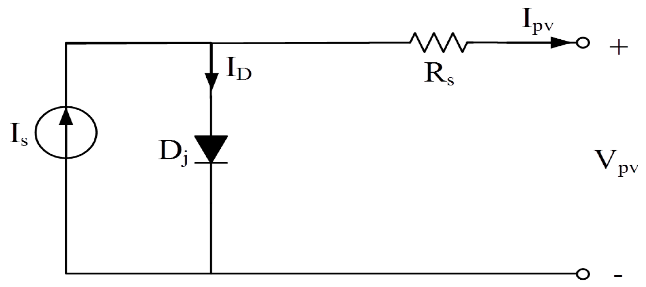
2.1. The Equivalent Circuit of PV Cells
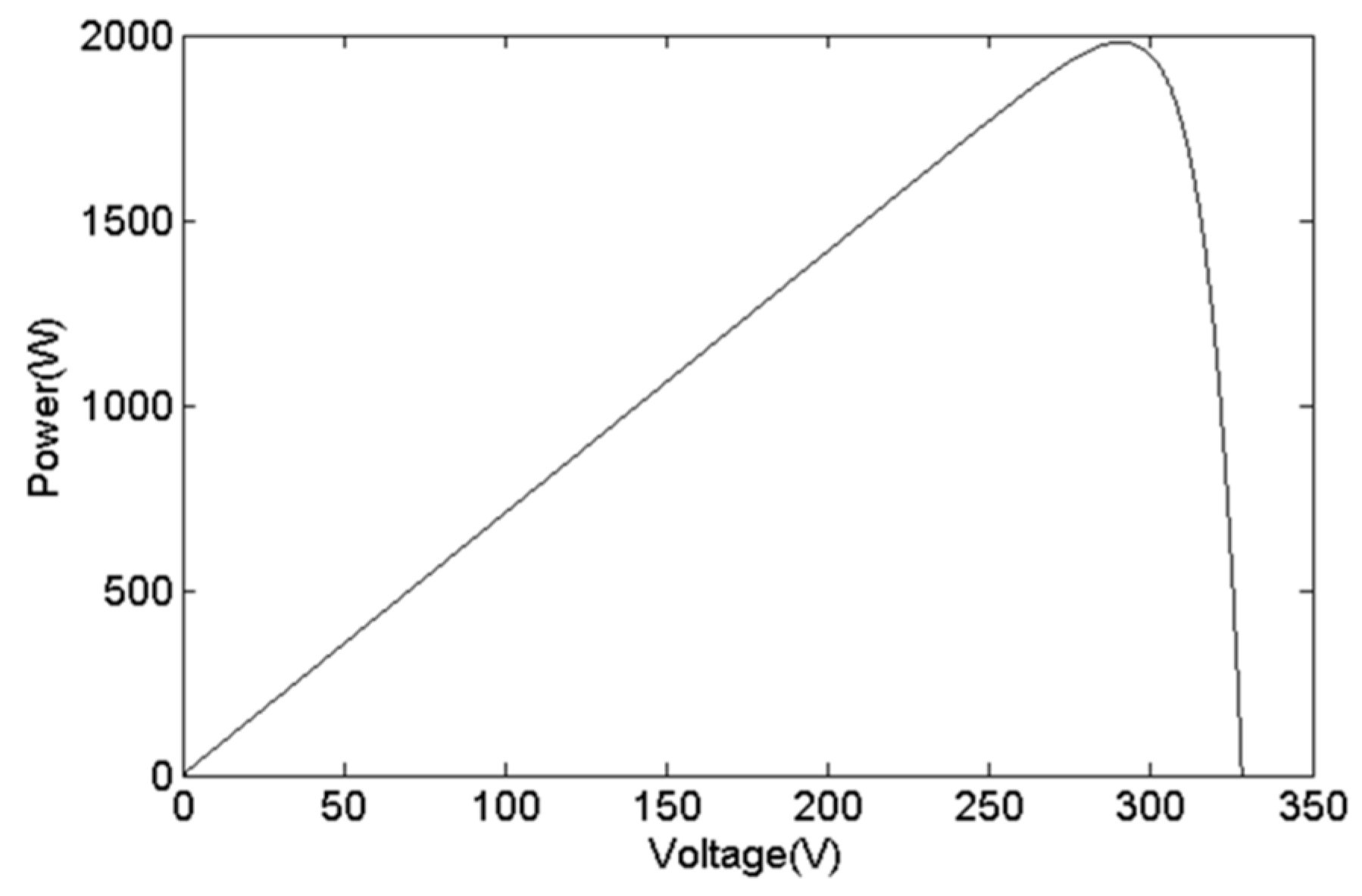
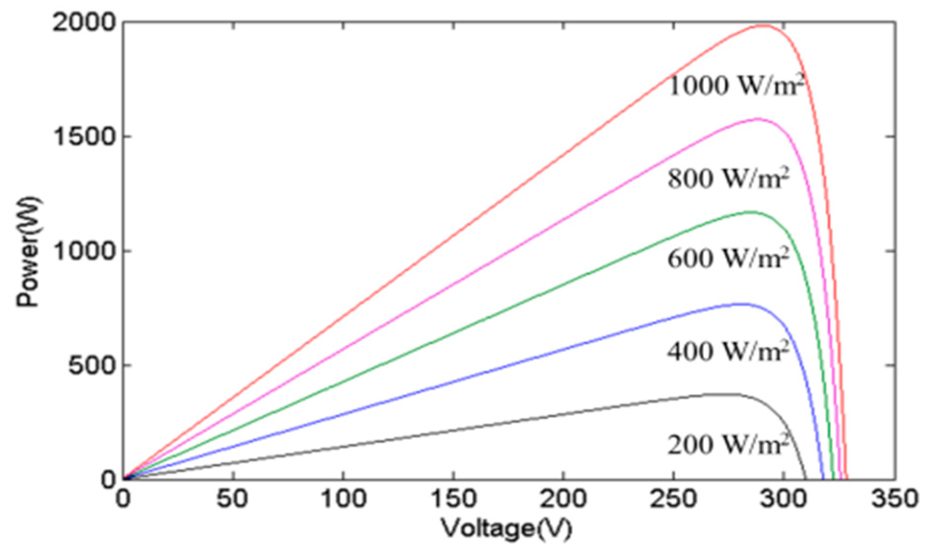
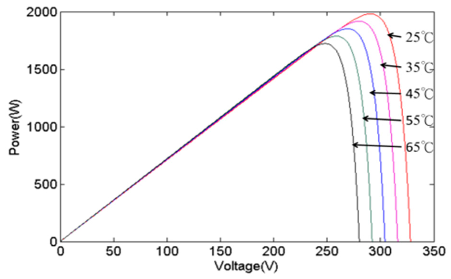
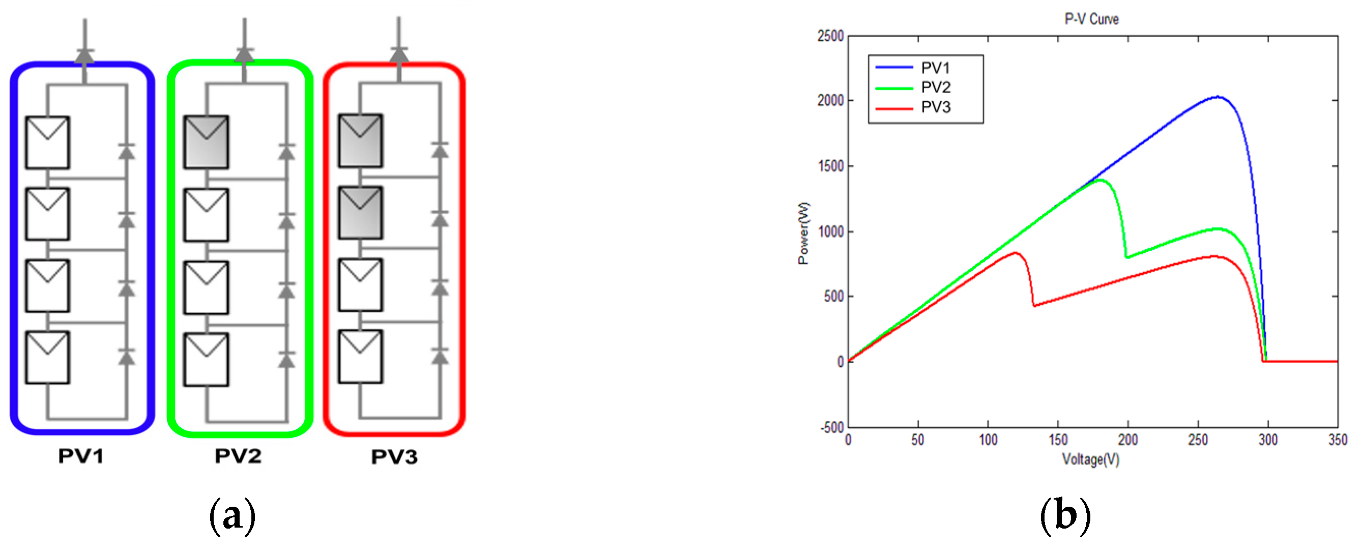
2.2. The Effects of Irradiance, Temperature, and PSC
3. IQPSO Algorithm
3.1. QPSO Algorithm
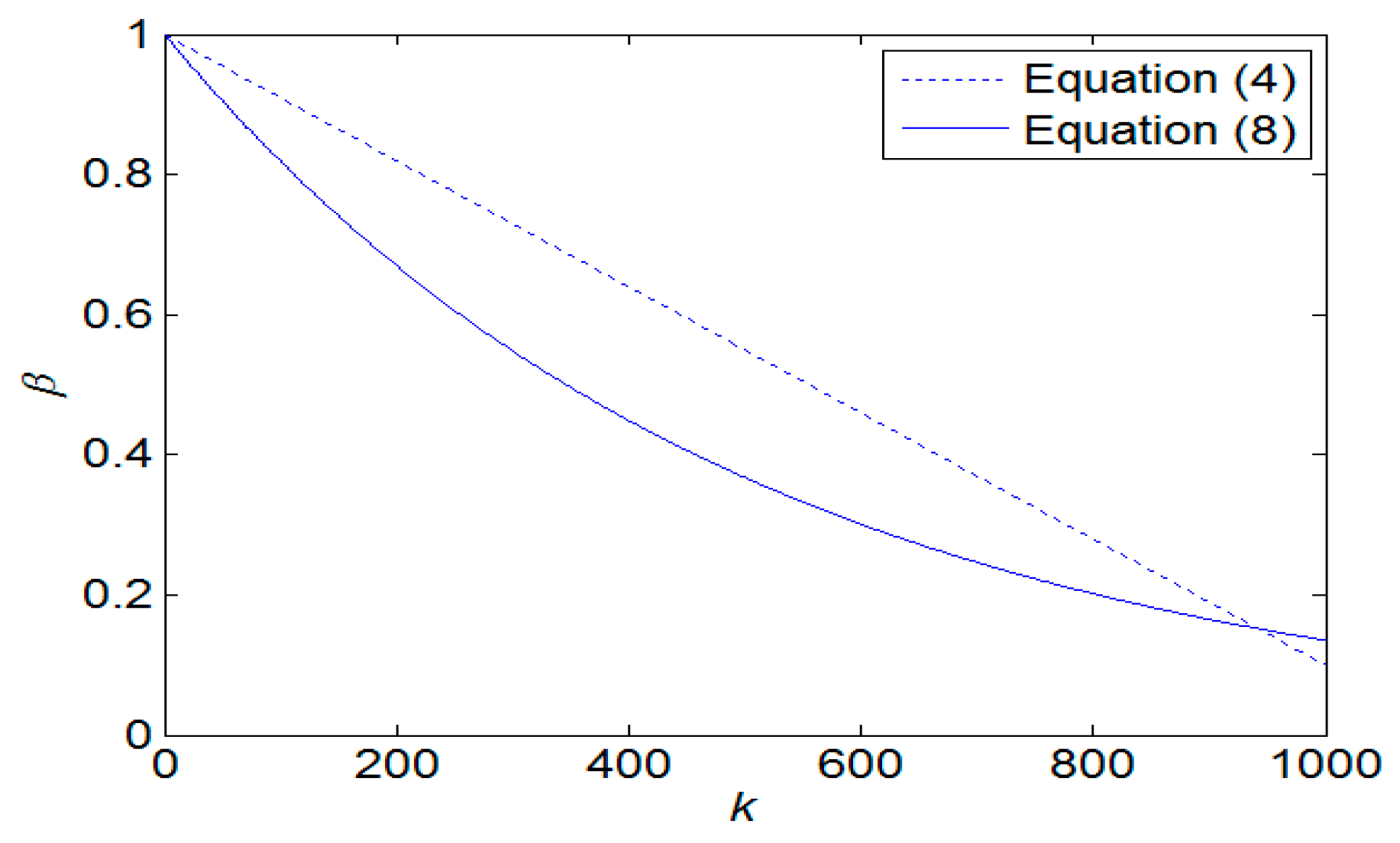
3.2. IQPSO Algorithm

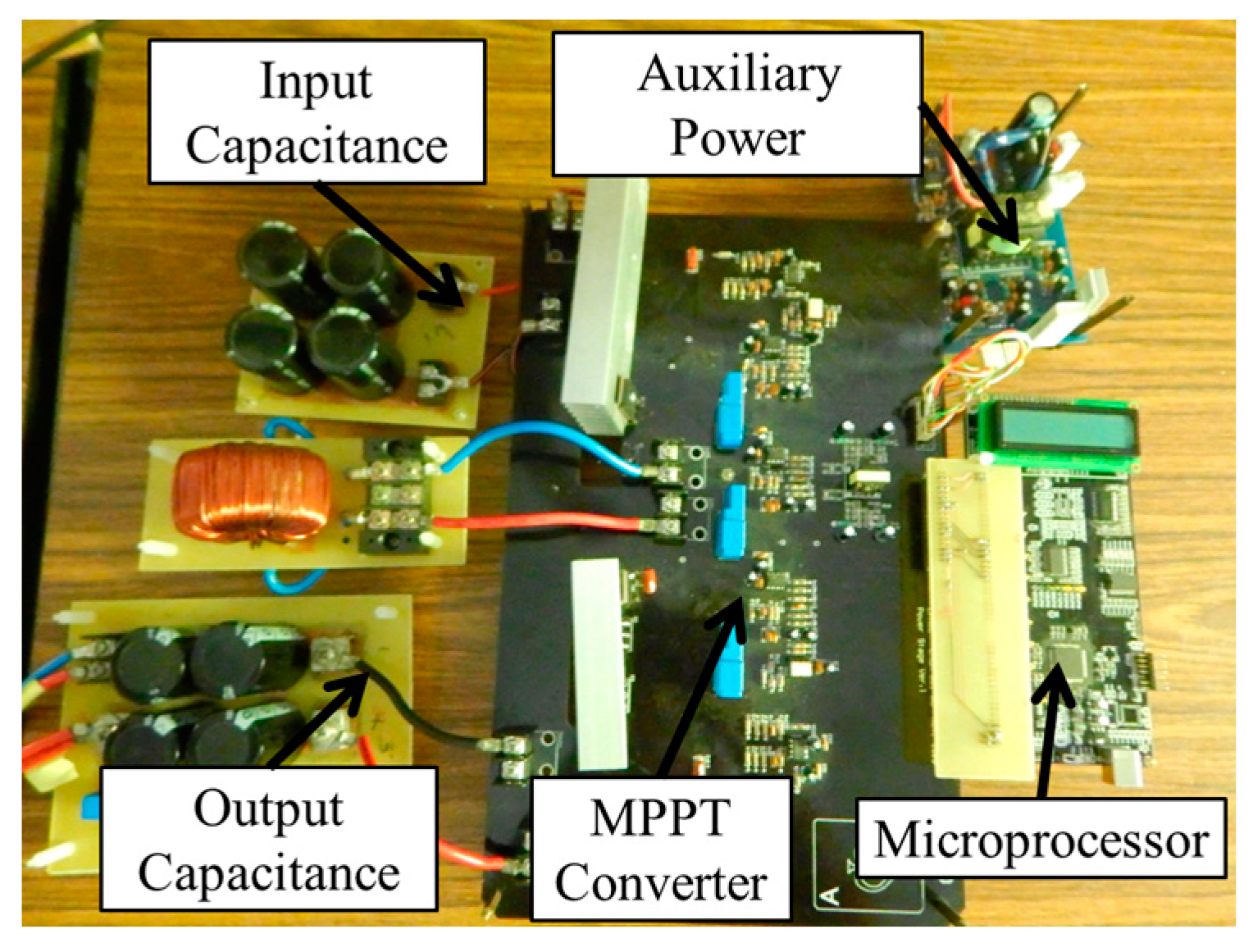
4. MPPT Circuit
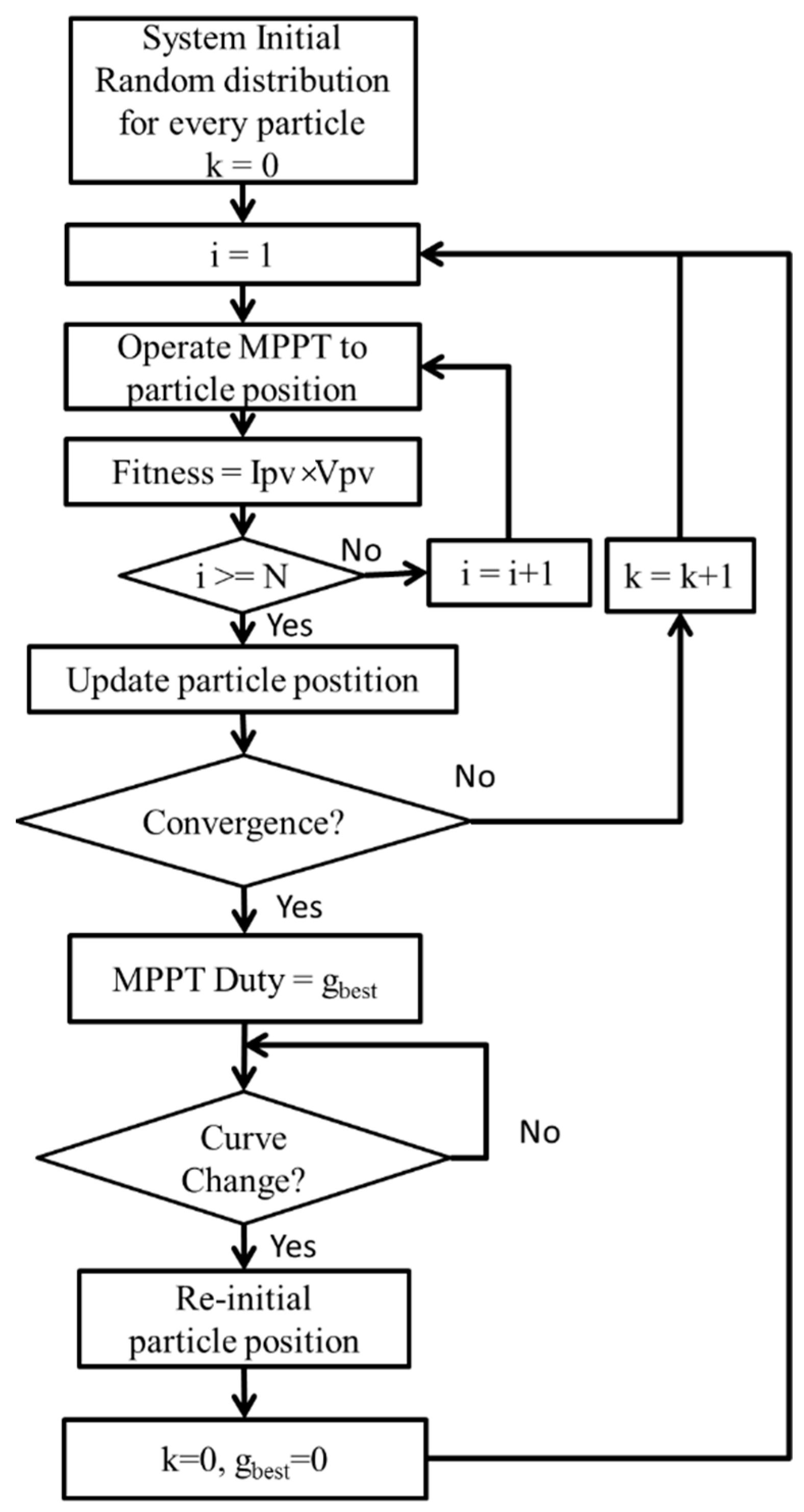
5. IQPSO MPPT

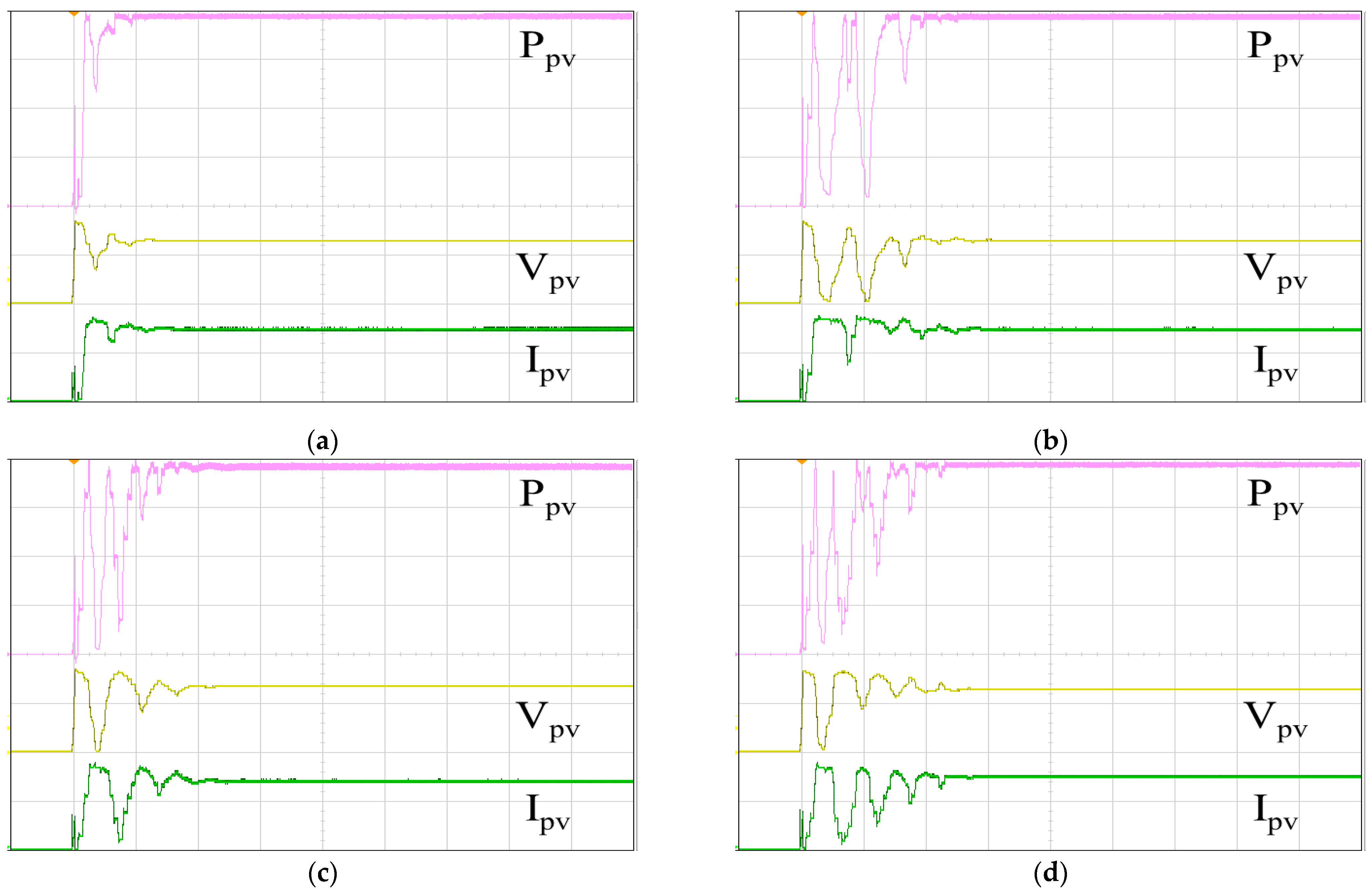
6. Experimental Results
7. Conclusions
Author Contributions
Funding
Institutional Review Board Statement
Data Availability Statement
Conflicts of Interest
References
- Suliman, F.; Anayi, F.; Packianather, M. Electrical faults analysis and detection in photovoltaic arrays based on machine learning classifiers. Sustainability 2024, 16, 1102. [Google Scholar] [CrossRef]
- Renewables 2023 Global Status Report. Available online: https://www.ren21.net/gsr-2023/ (accessed on 30 January 2024).
- Rimar, M.; Fedak, M.; Vahovsky, J.; Kulikov, A.; Oravec, P.; Kulikova, O.; Smajda, M.; Kana, M. Performance evaluation of elimination of stagnation of solar thermal systems. Processes 2020, 8, 621. [Google Scholar] [CrossRef]
- Rimar, M.; Fedak, M.; Hatala, M.; Smeringai, P. The synergistic effect of thermal collectors rotation in relation to their energy efficiency and stagnation compared with the static thermal system in the conditions of central Europe. Int. J. Photoenergy 2015, 2015, 321843. [Google Scholar] [CrossRef]
- Venkatramanan, D.; John, V. Dynamic modeling and analysis of buck converter based solar PV charge controller for improved MPPT performance. IEEE Trans. Ind. Appl. 2019, 55, 6234–6246. [Google Scholar] [CrossRef]
- Azad, M.A.; Tariq, M.; Sarwar, A.; Sajid, I.; Ahmad, S.; Bakhsh, F.I.; Sayed, A.E. A particle swarm optimization–adaptive weighted delay velocity-based fast-converging maximum power point tracking algorithm for solar PV generation system. Sustainability 2023, 15, 15335. [Google Scholar] [CrossRef]
- Liu, H.; Khan, M.Y.A.; Yuan, X. Hybrid maximum power extraction methods for photovoltaic systems: A comprehensive review. Energies 2023, 16, 5665. [Google Scholar] [CrossRef]
- Raiker, G.A.; Loganathan, U.; Subba, R.B. Current control of boost converter for PV interface with momentum-based perturb and observe MPPT. IEEE Trans. Ind. Inform. 2021, 57, 4071–4079. [Google Scholar] [CrossRef]
- López-Erauskin, R.; González, A.; Petrone, G.; Spagnuolo, G.; Gyselinck, J. Multi-variable perturb and observe algorithm for grid-tied PV systems with joint central and distributed MPPT configuration. IEEE Trans. Ind. Inform. 2021, 12, 360–367. [Google Scholar] [CrossRef]
- Swaminathan, N.; Lakshminarasamma, N.; Cao, Y. A fixed zone perturb and observe MPPT technique for a standalone distributed PV system. IEEE J. Emerg. Sel. Top. Power Electron. 2022, 10, 361–374. [Google Scholar] [CrossRef]
- Karabacak, M.; Fernández-Ramírez, L.M.; Kamal, T.; Kamal, S. A new hill climbing maximum power tracking control for wind turbines with inertial effect compensation. IEEE Trans. Ind. Electron. 2019, 66, 8545–8556. [Google Scholar] [CrossRef]
- Sabir, B.; Lu, S.-D.; Liu, H.-D.; Lin, C.-H.; Sarwar, A.; Huang, L.-Y. A novel isolated intelligent adjustable buck-boost converter with hill climbing MPPT algorithm for solar power systems. Processes 2023, 11, 1010. [Google Scholar] [CrossRef]
- Gupta, A.K.; Pachauri, R.K.; Maity, T.; Chauhan, Y.K.; Mahela, O.P.; Khan, B.; Gupta, P.K. Effect of various incremental conductance MPPT methods on the charging of battery load feed by solar panel. IEEE Access 2021, 9, 90977–90988. [Google Scholar] [CrossRef]
- Abdullah, B.U.D.; Lata, S.; Jaiswal, S.P.; Bhadoria, V.S.; Fotis, G.; Santas, A.; Ekonomou, L. A hybrid artificial ecosystem optimizer and incremental-conductance maximum-power-point-tracking-controlled grid-connected photovoltaic system. Energies 2023, 16, 5384. [Google Scholar] [CrossRef]
- Rezk, H.; Aly, M.; Al-Dhaifallah, M.; Shoyama, M. Design and hardware implementation of new adaptive fuzzy logic-based MPPT control method for photovoltaic applications. IEEE Access 2019, 7, 106427–106438. [Google Scholar] [CrossRef]
- Ali, M.N.; Mahmoud, K.; Lehtonen, M.; Darwish, M.M.F. An efficient fuzzy-logic based variable-step incremental conductance MPPT method for grid-connected PV systems. IEEE Access 2021, 9, 26420–26430. [Google Scholar] [CrossRef]
- Dehghani, M.; Taghipour, M.; Gharehpetian, G.B.; Abedi, M. Optimized fuzzy controller for MPPT of grid-connected PV systems in rapidly changing atmospheric conditions. J. Mod. Power Syst. Clean Energy 2021, 9, 376–383. [Google Scholar] [CrossRef]
- Šegota, S.B.; Anđelić, N.; Mrzljak, V.; Lorencin, I.; Kuric, I.; Car, Z. Utilization of multilayer perceptron for determining the inverse kinematics of an industrial robotic manipulator. Int. J. Adv. Robot. Syst. 2021, 18, 1–11. [Google Scholar] [CrossRef]
- Kumar, N.; Singh, B.; Panigrahi, B.K. PNKLMF-based neural network control and learning-based HC MPPT technique for multiobjective grid integrated solar PV based distributed generating system. IEEE Trans. Ind. Inform. 2019, 15, 3732–3742. [Google Scholar] [CrossRef]
- Priyadarshi, N.; Padmanaban, S.; Holm-Nielsen, J.B.; Blaabjerg, F.; Bhaskar, M.S. An experimental estimation of hybrid ANFIS–PSO-based MPPT for PV grid integration under fluctuating sun irradiance. IEEE Syst. J. 2020, 14, 1218–1229. [Google Scholar] [CrossRef]
- Sága, M.; Bednár, R.; Vaško, M. Contribution to modal and spectral interval finite element analysis. In Vibration Problems ICOVP 2011, Springer Proceedings in Physics; Náprstek, J., Horáček, J., Okrouhlík, M., Marvalová, B., Verhulst, F., Sawicki, J., Eds.; Springer: New York, NY, USA, 2011; Volume 139, pp. 269–274. [Google Scholar]
- Houssein, E.H.; Oliva, D.; Samee, N.A.; Mahmoud, N.F.; Emam, M.M. Liver Cancer Algorithm: A novel bio-inspired optimizer. Comput. Biol. Med. 2023, 165, 107389. [Google Scholar] [CrossRef]
- Li, S.; Chen, H.; Wang, M.; Heidari, A.A.; Mirjalili, S. Slime mould algorithm: A new method for stochastic optimization. Future Gener. Comput. Syst. 2020, 111, 300–323. [Google Scholar] [CrossRef]
- Li, J.; Yang, Y.-H.; An, Q.; Lei, H.; Deng, Q.; Wang, G.-G. Moth Search: Variants, Hybrids, and Applications. Mathematics 2022, 10, 4162. [Google Scholar] [CrossRef]
- Tu, J.; Chen, H.; Wang, M.; Gandomi, A.H. The Colony Predation Algorithm. J. Bionic Eng. 2021, 18, 674–710. [Google Scholar] [CrossRef]
- Ahmadianfar, I.; Asghar Heidari, A.; Noshadian, S.; Chen, H.; Gandomi, A.H. INFO: An Efficient Optimization Algorithm based on Weighted Mean of Vectors. Expert Syst. Appl. 2022, 195, 116516. [Google Scholar] [CrossRef]
- Heidari, A.A.; Mirjalili, S.; Faris, H.; Aljarah, I.; Mafarja, M.; Chen, H. Harris hawks optimization: Algorithm and applications. Future Gener. Comput. Syst. 2019, 97, 849–872. [Google Scholar] [CrossRef]
- Su, H.; Zhao, D.; Heidari, A.A.; Liu, L.; Zhang, X.; Mafarja, M.; Chen, H. RIME: A physics-based optimization. Neurocomputing 2023, 532, 183–214. [Google Scholar] [CrossRef]
- Figueiredo, S.N.; Aquino, R.N.A.L.S. Hybrid MPPT technique PSO-P&O applied to photovoltaic systems under uniform and partial shading conditions. IEEE Lat. Am. Trans. 2021, 19, 1610–1617. [Google Scholar]
- Qin, Y.; Pun, C.-M.; Hu, H.; Gao, H. Logistic Quantum-behaved Particle Swarm Optimization Based MPPT for PV Systems. In Proceedings of the 2017 Seventh International Conference on Information Science and Technology (ICIST), Da Nang, Vietnam, 16–19 April 2017. [Google Scholar]
- Huang, Y.-P.; Huang, M.-Y.; Ye, C.-E. A fusion firefly algorithm with simplified propagation for photovoltaic MPPT under partial shading conditions. IEEE Trans. Sustain. Energy 2020, 11, 2641–2652. [Google Scholar] [CrossRef]
- Agwa, A.M.; Alanazi, T.I.; Kraiem, H.; Touti, E.; Alanazi, A.; Alanazi, D.K. MPPT of PEM fuel cell using PI-PD controller based on golden jackal optimization algorithm. Biomimetics 2023, 8, 426. [Google Scholar] [CrossRef]
- Ballaji, A.; Dash, R.; Subburaj, V.; Reddy, K.J.; Swain, D.; Swain, S.C. Design & development of MPPT using PSO with predefined search space based on fuzzy fokker planck solution. IEEE Access 2022, 10, 80764–80783. [Google Scholar]
- Kacimi, N.; Idir, A.; Grouni, S.; Boucherit, M.S. Improved MPPT control strategy for PV connected to grid using IncCond-PSO-MPC approach. CSEE J. Power Energy Syst. 2023, 9, 1008–1020. [Google Scholar]
- Ibrahim, M.H.; Ang, S.P.; Dani, M.N.; Rahman, M.I.; Petra, R.; Sulthan, S.M. Optimizing step-size of perturb & observe and incremental conductance MPPT techniques using PSO for grid-tied PV system. IEEE Access 2023, 11, 13079–13090. [Google Scholar]
- Sangrody, R.; Taheri, S.; Cretu, A.-M.; Pouresmaeil, E. An improved PSO-based MPPT technique using stability and steady state analyses under partial shading conditions. IEEE Trans. Sustain. Energy 2024, 15, 136–145. [Google Scholar] [CrossRef]
- Watanabe, R.B.; Junior, O.H.A.; Leandro, P.G.M.; Salvadori, F.; Beck, M.F.; Pereira, K.; Brandt, M.H.M.; Oliverira, F.M.D. Implementation of the bio-inspired metaheuristic firefly algorithm (FA) applied to maximum power point tracking of photovoltaic systems. Energies 2022, 15, 5338. [Google Scholar] [CrossRef]
- Liu, F.; Gao, J.; Liu, H. A fault diagnosis solution of rolling bearing based on MEEMD and QPSO-LSSVM. IEEE Access 2020, 8, 101476–101488. [Google Scholar] [CrossRef]
- Huang, C.; Fei, J.; Deng, W. A novel route planning method of fixed-wing unmanned aerial vehicle based on improved QPSO. IEEE Access 2020, 8, 65071–65084. [Google Scholar] [CrossRef]
- Guo, L. Research on anomaly detection in massive multimedia data transmission network based on improved PSO algorithm. IEEE Access 2020, 8, 95368–95377. [Google Scholar] [CrossRef]
- Cao, Y.; Wang, W.; Ma, L.; Wang, X. Inverse Kinematics Solution of Redundant Degree of Freedom Robot Based on Improved Quantum Particle Swarm Optimization. In Proceedings of the 2021 7th International Conference on Control Science and Systems Engineering (ICCSSE), Qingdao, China, 30 July–1 August 2021. [Google Scholar]
- Fang, X.; Ruan, Z.; Zhao, S.; Liu, F. Conditional disturbance-compensation control for an overactuated manned submersible vehicle. IEEE Trans. Ind. Inform. 2023, 20, 4828–4838. [Google Scholar] [CrossRef]
- Hortobágyi, Á.; Pivarčiová, E.; Koleda, P. Holographic interferometry for measuring the effect of thermal modification on wood thermal properties. Appl. Sci. 2021, 11, 2516. [Google Scholar] [CrossRef]
- Bekiroglu, E.; Yazar, M.D. MPPT control of grid connected DFIG at variable wind speed. Energies 2022, 15, 3146. [Google Scholar] [CrossRef]
- Priyadarshi, N.; Bhaskar, M.S.; Almakhles, D. A novel hybrid whale optimization algorithm differential evolution algorithm-based maximum power point tracking employed wind energy conversion systems for water pumping applications: Practical realization. IEEE Trans. Ind. Electron. 2024, 71, 1641–1652. [Google Scholar] [CrossRef]
- Pillai, D.S.; Ram, J.P.; Garcia, J.L.; Kim, Y.-J.; Catalão, J.P.S. Experimental studies on a new array design and maximum power tracking strategy for enhanced performance of soiled photovoltaic systems. IEEE Trans. Power Electron. 2024, 39, 1596–1608. [Google Scholar] [CrossRef]
- Alkhafaji, A.S.; Trabelsi, H. Uses of superconducting magnetic energy storage systems in microgrids under unbalanced inductive loads and partial shading conditions. Energies 2022, 15, 8597. [Google Scholar] [CrossRef]
- Tang, R. Large-scale photovoltaic system on green ship and its MPPT controlling. Sol. Energy 2017, 157, 614–628. [Google Scholar] [CrossRef]


| System Power | 2000 W |
| Input voltage Vpv | 10–560 V |
| Output voltage Vo | 100–400 V |
| Inductor LM | 1.2 mH |
| Input capacitor Cin | 560 μF |
| Output capacitor Cout | 560 μF |
| Method | PSO | FA | QPSO | IQPSO | ||||
|---|---|---|---|---|---|---|---|---|
| Parameter | W | 0.3 | A | 0.02 | βmax | 1.0 | γ | 2.0 |
| C1 | 0.5 | Β | 0.50 | βmin | 0.1 | |||
| C2 | 0.5 | Γ | 0.50 | |||||
| Maximum Power (W) | Tracking Power (W) | Tracking Accuracy | Tracking Time (s) | |
|---|---|---|---|---|
| IQPSO | 1999.92 | 1980.59 | 99.03 % | 1.32 |
| QPSO | 1999.92 | 1969.62 | 98.48 % | 3.93 |
| FA | 1999.92 | 1926.04 | 96.31 % | 2.81 |
| PSO | 1999.92 | 1954.81 | 97.74 % | 4.51 |
| Tracking Power (W) | Tracking Accuracy | Tracking Time (s) | |
|---|---|---|---|
| IQPSO w/o Equation (8) CHG | 1970.12 | 98.51 % | 2.91 |
| IQPSO w/o Equation (9) CHG | 1977.32 | 98.87 % | 2.32 |
| IQPSO w/o Equation (10) CHG | 1972.32 | 98.62 % | 2.51 |
| IQPSO w/o Equation (11) CHG | 1976.12 | 98.81 % | 2.38 |
| Maximum Power (W) | Tracking Power (W) | Tracking Accuracy | Tracking Time (s) | |
|---|---|---|---|---|
| IQPSO | 1260.02 | 1244.99 | 98.81 % | 1.93 |
| QPSO | 1260.02 | 1239.55 | 98.38 % | 6.78 |
| FA | 1260.02 | 1215.66 | 96.48 % | 2.61 |
| PSO | 1260.02 | 1205.78 | 95.70 % | 5.41 |
| Tracking Power (W) | Tracking Accuracy | Tracking Time (s) | |
|---|---|---|---|
| IQPSO w/o Equation (8) CHG | 1240.09 | 98.42 % | 4.51 |
| IQPSO w/o Equation (9) CHG | 1243.99 | 98.73 % | 2.42 |
| IQPSO w/o Equation (10) CHG | 1241.48 | 98.53 % | 3.83 |
| IQPSO w/o Equation (11) CHG | 1243.75 | 98.71 % | 3.25 |
| Average Tracking Accuracy | Average Tracking Time (s) | |
|---|---|---|
| IQPSO | 99.84 % | 2.04 |
| QPSO | 98.73 % | 3.60 |
| FA | 98.55 % | 2.37 |
| PSO | 98.51 % | 3.29 |
| Irradiance (W/m2) | Temperature (°C) | Maximum Power (W) | Tracking Power (W) | Tracking Accuracy | Tracking Time (s) | |
|---|---|---|---|---|---|---|
| IQPSO | 825 | 35.0 | 1314 | 1307 | 99.47 % | 1.35 |
| QPSO | 791 | 35.8 | 1317 | 1304 | 99.01 % | 4.42 |
| FA | 780 | 38.1 | 1339 | 1308 | 98.35 % | 2.35 |
| PSO | 804 | 34.5 | 1272 | 1255 | 98.66 % | 5.43 |
| Irradiance (W/m2) | Temperature (°C) | Maximum Power (W) | Tracking Power (W) | Tracking Accuracy | Tracking Time (s) | |
|---|---|---|---|---|---|---|
| IQPSO | 986 | 39.6 | 1065 | 1064 | 99.91 % | 1.73 |
| QPSO | 1010 | 37.8 | 1005 | 997 | 99.20 % | 3.86 |
| FA | 975 | 38.1 | 967 | 948 | 98.03 % | 1.93 |
| PSO | 977 | 38.8 | 968 | 941 | 97.21 % | 4.63 |
| IQPSO | QPSO | FA | PSO | |
|---|---|---|---|---|
| Day1 | 6703.66 | 6388.45 | 6422.04 | 6000.40 |
| Day2 | 10,521.22 | 10,408.85 | 10,319.25 | 10,164.69 |
| Day3 | 9382.16 | 9284.92 | 9211.54 | 9072.42 |
| Total | 26,607.04 | 26,082.22 | 25,952.83 | 25,237.51 |
Disclaimer/Publisher’s Note: The statements, opinions and data contained in all publications are solely those of the individual author(s) and contributor(s) and not of MDPI and/or the editor(s). MDPI and/or the editor(s) disclaim responsibility for any injury to people or property resulting from any ideas, methods, instructions or products referred to in the content. |
© 2024 by the authors. Licensee MDPI, Basel, Switzerland. This article is an open access article distributed under the terms and conditions of the Creative Commons Attribution (CC BY) license (https://creativecommons.org/licenses/by/4.0/).
Share and Cite
Yu, G.-R.; Chang, Y.-D.; Lee, W.-S. Maximum Power Point Tracking of Photovoltaic Generation System Using Improved Quantum-Behavior Particle Swarm Optimization. Biomimetics 2024, 9, 223. https://doi.org/10.3390/biomimetics9040223
Yu G-R, Chang Y-D, Lee W-S. Maximum Power Point Tracking of Photovoltaic Generation System Using Improved Quantum-Behavior Particle Swarm Optimization. Biomimetics. 2024; 9(4):223. https://doi.org/10.3390/biomimetics9040223
Chicago/Turabian StyleYu, Gwo-Ruey, Yong-Dong Chang, and Weng-Sheng Lee. 2024. "Maximum Power Point Tracking of Photovoltaic Generation System Using Improved Quantum-Behavior Particle Swarm Optimization" Biomimetics 9, no. 4: 223. https://doi.org/10.3390/biomimetics9040223
APA StyleYu, G.-R., Chang, Y.-D., & Lee, W.-S. (2024). Maximum Power Point Tracking of Photovoltaic Generation System Using Improved Quantum-Behavior Particle Swarm Optimization. Biomimetics, 9(4), 223. https://doi.org/10.3390/biomimetics9040223