1. Introduction
The new generation of high-gradient linear accelerators is extremely demanding in order to produce high-brightness electron beams. These beams are used in a great number of applications, including future linear colliders, X-ray Free-Electron Lasers (FELs), and inverse Compton scattering accelerators for research, compact, or portable devices for radiotherapy, mobile cargo inspections and security, biology, energy, and environmental applications [
1,
2,
3,
4,
5].
In the framework of the Compact Light XLS project [
4], a short ultra-high gradient linearizer working on the third harmonic (∼36 GHz) of the bunched electron beam and generated by a high-voltage DC gun (up to 480 kV) operating with an accelerating gradient of ∼150 MV/m (i.e., 15–20 MV integrated voltage range) is requested [
6,
7]. To meet these requirements, a 36-GHz pulsed Ka-band RF power source with a pulse length of 100 ns and a repetition frequency in the (1–10) Hz range with an output power of (50–60) MW is necessary [
1,
2,
3,
8,
9,
10,
11,
12,
13].
In our previous paper we proposed a high power source with a Ka-band harmonic klystron with the output cavity consisting of a 36-GHz output extended interaction cavity. This strategy allows one to optimize klystron conversion efficiency up to 42% to achieve 20-MW peak RF power to be used to feed the linearizer while working at 150 MV/m of accelerating gradient as requested by all challenging next generation projects.
The klystron can be used to provide short pulse with controlled phase look loop. Other high power oscillators, like gyrotrons, being a long pulse oscillators, should require more complex circuitry, including choppers and can be affected by jitter and phase noise. For instance, before, to establish the permanent regime, a gyrotron needed to be place in the correct working point to excite a specific cavity mode. This process requires some microseconds, while the desired pulse for the target application is in the nanosecond range.
The klystron amplifier design requires a proper choice of some parameters: Perveance, beam, and pipe diameters, focusing magnetic field, bunching cavities and output cavity system, ultra-vacuum system, coupling coefficient, plasma frequency reduction factor, and beam collector. Among them, the perveance, which is one of the challenging aspects of the high power klystron design has a key role in designing the electron gun. The lower the perveance, the weaker the space charge, and, consequently, the stronger the bunching. On the other hand, higher perveance causes strong space charge leading to low efficiency because of weak bunching [
14]. As a result, finding an optimal perveance to maintain a good efficiency is always a challenging point in electron gun design. In this paper, we present an electron gun in the Ka-band with a focusing magnetic device producing a beam radius of 1 mm with the minimum scalloping of 0.98, and confined in a 1.2-mm beam pipe in order to maximize the klystron efficiency. The reason why we kept the scalloping effect within 2% is that it is an optimized value for the klystron efficiency [
15]. We show that, with a proper focusing magnetic field, we could manage to minimize the scalloping effect for increasing the coupling parameters. The electron gun geometry is optimized to adjust the electric field equipotential lines for obtaining an extracted beam current of 100 A. Estimations have been obtained by using the numerical code CST Particle Studio [
16] and analytical approach. The analytical results for calculation of the electron gun dimensions have been compared with numerical estimations.
2. Design Procedure of the Electron Gun and Focusing Magnetic Field
The main design parameters of an electron gun and focusing magnetic field demand:
(1) To find an optimal perveance. The perveance is defined as and it is the parameter by which we control and measure the space charge force. I and V stand for the beam current and voltage, respectively. The higher the perveance, the lower efficiency and vice versa. We have chosen a low micro-perveance of 0.3 for our device so that we have a high efficiency. In the following section, it will be demonstrated that the difference between relativistic current density and Child–Langmuir (non-relativistic regime) is small enough that we can consider the non-relativistic approach for calculating the perveance.
(2) Define an optimal electrostatic beam compression ratio and the maximum electric field on the focusing electrode: By solving the Poisson’s equation in spherical coordinates and with the help of the electrostatic lens effect, which is a bridge between light and charged-particle optics, we can find the potential distribution between cathode and anode and consequently it is possible to optimize the geometry of the electron gun in order to have a high electrostatic beam compression ratio and a low electric field strength on the focusing electrode. The electrostatic beam compression ratio has been chosen to be 1500:1 and the maximum electric field on the focusing electrode is about 200 kV/cm. The procedure for estimating the dimensions of the electron gun device is as follows:
Poisson’s equation in spherical coordinates is given:
where
is the vacuum permittivity, and
is the electron velocity, related to the voltage V by
with
as the electron mass and
e its charge. The final solution of the above equation is given by [
17,
18],
where,
and
where
and
are the radii of the spheres of anode and cathode, respectively (see Figure (1b)) [
19].
From Equation (2), the beam current is proportional to 3/2 power of the cathode voltage and the constant of proportionality is the perveance. The other parameters, like the beam angle
(
) and anode aperture radius can be obtained from electrostatic lens effect by considering the analogy between light and charged-particle optics [
20] (see
Figure 1a,b). The aperture lens can be obtained [
21]:
where
F is the aperture number,
stands for the difference of the energy gradients, the subscripts 1 and 2 refer to the entrance and exit of the section, and
p and
v are the momentum and velocity of the charged particles. The higher the aperture number,
F, the smaller the aperture hole becomes.
(3) Define the minimum beam radius in magnetic system; to avoid the increase of the transverse dimensions of the beam inside the beam pipe, after the electron gun exit, due to the existence of space charge, a transverse focusing magnet is needed. The axial magnetic field distribution and the beam trajectory along the propagation direction are shown in
Figure 1c,d. We reported the design parameters of the gun with the focusing magnetic field along the beam axis in
Table 1. It should be noted that the maximum possible beam compression (minimum beam radius) is necessary to avoid the voltage breakdown [
10]. By minimizing the beam radius, the transverse emittance rises and beam scalloping will start to increase. Through an appropriate focusing magnet system, we obtain an scalloping effect within 2%, which is an optimal number for the klystron efficiency [
15]. It should be noted that, by having a proper beam dimension, we will get the optimum interaction with the output RF cavities [
22].
In
Table 2, we compared the analytical and numerical results (Equations (3) and (4)) for estimating the dimensions of the electron gun device obtaining a good agreement.
(4) Define the opportune magnetostatic beam compression ratio: The magnetic field profile, shown in
Figure 1c, has two peaks of 7 kG and 32 kG. The bigger one is located along a distance of about 300 mm, to obtain a narrow beam radius to allow cavities to operate on the third harmonic of the fundamental mode of X-band. These cavities work in the Ka-band regime and therefore they require a small beam radius of about 1 mm. The magnetostatic beam compression ratio of 1700:1 is located in this region. It should be noted that the maximum possible compression ratio occurs when the beam radius reaches the Brillouin limit [
10]. In the next section we will show that the beam radius of 1 mm is far away from the Brillouin limit and the diamagnetic field effect is negligible.
We will also show why we can use the non-relativistic approach to calculate perveance and how we can neglect the diamagnetic field effect due to the rotation in the magnetic field.
3. Relativistic Approach to the Design
As we mentioned in the previous section, to get a high efficiency klystron, we need to design a low perveance electron gun. In this section we will show that a non-relativistic approach for calculating the perveance is reliable if the difference between relativistic current density and Child–Langmuir limit current density (non-relativistic regime) is very low. Then, it will be demonstrated that the diamagnetic field effect is also negligible due to the fact that the rotation frequency is much smaller than Larmor frequency and that the beam radius is also far away from the Brillouin limit. Finally, we will achieve the minimum scalloping effect for increasing the coupling parameters by combining the beam propagation with a proper focusing magnetic field [
11].
It is known that Brillouin flow is produced when the sum of the radial forces on the electrons constituting the stream become continuously equal to zero. For this condition the following equation must be satisfied along the stream [
23]:
where,
and
is called the Larmor frequency, is called the cyclotron frequency, is called the plasma frequency, B is the axial flux density of the magnetic field, e is the electron charge (negative), is the electron mass, I is the current in the electron stream, V is the stream voltage, and are the magnetic fluxes linking the helical path of an electron at two points (departure point and Brilliouin radius, respectively) along the stream, and is the equilibrium radius of the beam.
It is desirable to make the cyclotron frequency equal to the Larmor frequency in producing Brilouin flow. Then Equation (5) becomes [
24,
25]:
Substituting Equations (6) and (7) into the above equation we obtain equilibrium radius of the beam as:
The author of [
10] estimated the Brillouin limit radius with the following equation:
that is derived from envelope equation in space charge domain, with the effect of an external magnetic field.
In our case, , , is the relativistic factor , and B is the magnetic field in kG kG. The Brillouin limit radius is about 0.1 mm.
In the region where magnetic field is 32 kG, the beam radius is ∼1 mm, considerably higher than Brillouin limit which is about 0.1 mm. Likewise for the region where the field is 7 kG, the beam radius is ∼2.2 mm which again is much bigger than the Brillouin limit which is about 0.4 mm.
We have also obtained the same limit for the beam radius by considering the Caryotakis approach [
15]. Therefore in both cases (B = 7 kG and 32 kG), the beam radius is far away from the Brillouin limit and the diamagnetic field effect is negligible. The next step is to calculate relativistic current density and compare it with the non-relativistic approach (Child–Langmuir regime) to get an idea of the difference between the relativistic perveance and non-relativistic regime. First we investigate this task for the planar diodes and then we extend the investigation to the spherical diodes. In the case of planar diodes, we will compare CL approach with relativistic one and for the spherical diodes we compare the classical Langmuir–Blodgett (LB) model with the relativistic approach. To accomplish this task, we define the relativistic perveance as
. The relativistic solution of the one-dimensional planar diode has been performed in [
26]:
where
is the ordinary hypergeometric functions having a general form of the kind:
where
are the rising factorial or Pochhammer symbols with:
and
In the case of non-relativistic regime we have [
17,
18]:
In
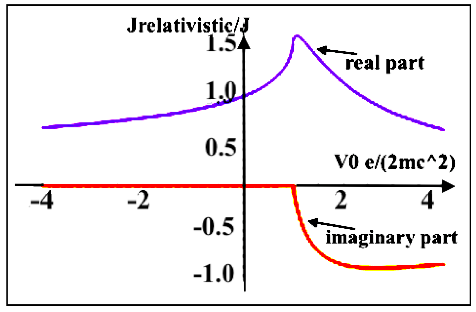
Figure 2, we have shown the ratio between the relativistic regime and non-relativistic one as a function of
.
For the cathode voltage of 480kV, the hypergeometric function becomes and the ratio between the relativistic current density and Child–Langmuir (CL) becomes about 0.92 ( = 0.92). This same ratio is also valid for the two perveances. We can then calculate that the difference between non-relativistic and relativistic regimes is less than 8% and we can consider the non-relativistic approach for calculating the perveance. To reduce the error one can reduce the cathode voltage.
In the case of spherical diodes, which is our case, the relativistic solution has also been accomplished in [
26]. They reached a conclusion of a 4% error between the relativistic and LB approaches for the case of spherical diodes in the range
, where the
and
are the anode and cathode radius, respectively. The ultra-relativistic approximation is given by [
26]:
in our case
=1/3.2, we are allowed to compare the above equation with the LB model concluding that the error is about 4%. The final investigation is dedicated to see how we can mitigate possible diamagnetic effects. The cyclotron frequency is determined according to the Busch’s theorem:
where
and
are the magnetic fluxes linking the helical path of an electron at two points (departure point and Brilliouin radius, respectively) along the stream. This equation, in the case of uniform axial flux density, can be written:
where
and
r are the radius of the electron path at the departure point and at the second mentioned point, respectively. In our case, with the minimun scalloping,
and
r = 1, the obtained rotation frequency is
and it means that the rotation frequency is much smaller than Larmor frequency and this mitigates the possible diamagnetic effects.


 ,
, 


