Article

Multichannel Time Synchronization Based on PTP through a High Voltage Isolation Buffer Network Interface for Thick-GEM Detectors

by
Luis Guillermo García Ordóñez
1,2,3,*,†,
Maria Liz Crespo
1,3,
Sergio Carrato
2,
Andres Cicuttin
1,3,
Werner Oswaldo Florian Samayoa
1,2,3,
Daniele D’Ago
3,4 and
Stefano Levorato
3
1
Multidisciplinary Laboratory (MLAB), International Centre for Theoretical Physics, 34151 Grignano, Italy
2
Department of Engineering and Architecture, Università degli Studi di Trieste, 34127 Trieste, Italy
3
Istituto Nazionale di Fisica Nucleare, Sezione di Trieste, 34149 Trieste, Italy
4
Department of Physics, Università degli Studi di Trieste, 34127 Trieste, Italy
*
Author to whom correspondence should be addressed.
Current address: Via Beirut 31, 34151 Grignano, Italy.
Instruments 2022, 6(1), 11; https://doi.org/10.3390/instruments6010011
Submission received: 31 December 2021 / Revised: 26 January 2022 / Accepted: 29 January 2022 / Published: 1 February 2022

Abstract

:
Data logging and complex algorithm implementations acting on multichannel systems with independent devices require the use of time synchronization. In the case of Gas Electron Multipliers (GEM) and Thick-GEM (THGEM) detectors, the biasing potential can be generated at the detector level via DC to DC converters operating at floating voltage. In this case, high voltage isolation buffers may be used to allow communication between the different channels. However, their use add non-negligible delays in the transmission channel, complicating the synchronization. Implementation of a simplified precise time protocol is presented for handling the synchronization on the Field Programmable Gate Array (FPGA) side of a Xilinx SoC Zynq ZC7Z030. The synchronization is done through a high voltage isolated bidirectional network interface built on a custom board attached to a commercial CIAA_ACC carrier. The results of the synchronization are shown through oscilloscope captures measuring the time drift over long periods of time, achieving synchronization in the order of nanoseconds.

1. Introduction

Gaseous detectors are an integral part of present and future instrumentation in particle physics. Micro-Pattern Gaseous Detectors (MPGD), namely Gas Electron Multipliers (GEM) and Micro-mesh Gaseous Structure (MICROMEGAS) are powerful and easy to manufacture in large sizes [1]. Thick-GEM (THGEM) detectors are robust multipliers with high gains ( 10 4 10 6 at 1 Torr) manufactured using standard Printed Circuit Board (PCB) technology [2]. These detectors need different bias voltages applied to the electrodes, often with values in the order of kV. In large area applications, said electrodes need to be segmented to prevent damage in the detector due the amount of energy dissipated through electrical discharges.
A High Voltage (HV) system for MPGDs requires precise current monitoring at the level of 10 pA with fine resolution to control the detector operation. A multistage structure of the detector requires highly correlated voltages applied to the electrodes. Changes of pressure and temperature cause gain variations and are more severe in the case of multistage detectors. Segmentation of the electrodes adds further elements of complexity in the HV system [3]. An active High Voltage Power Supply System (HVPSS) based on Field Programmable Gate Array, System on Chip (FPGA/SoC) suited for MPGD technologies has been designed and tested as a step towards multichannel applications [4].
The HVPSS provides true real-time monitoring, allowing to perform research and development using the detailed time-stamped information to understand the precise evolution of break-down events. To study fast transient, such as the propagation of electrical discharges in different segments of an electrode, a time-stamp resolution for current/voltage monitoring in the order of 10 ns or better is needed [5]. Local time-stamping can be done in the order of 2 ns due to a 500-MHz Analog to Digital Converter (ADC). However, to track the propagation of electrical discharges through multiple channels, it is necessary to keep them synchronized within the same order of magnitude.
A multichannel HVPSS allows the implementation of automatic protocols to stabilize the gain during pressure and temperature variation as well as to prevent possible unstable conditions without user intervention. This configuration also enables logging environmental conditions during fast transients so as to study the propagation of electrical discharges between electrodes and segments for further studies on critical conditions with the final goal of preventing them.
To avoid the propagation of electronic noise in the detector, each electrode needs to be connected to the HV power domain with independent floating power supplies. The absolute voltage among channels may reach up to 2 kV, making a direct galvanic connection among them impossible. Wireless communication is not recommended to prevent electromagnetic noise induction in the detector; consequently, a High Voltage Isolated Bidirectional Network Interface (HVIBNI) for safe data transmission among multiple HVPS control units was designed [6].
To keep a coherent response of any algorithm and to keep an accurate data logging of the entire system, all channels have to be synchronized with a common clock. However, the use of isolation buffers and the physical length of the cables introduce signal delays that need to be characterized in order to have accurate time synchronization. This individual characterization may be inconvenient for a scalable system. A time synchronization method based on the IEEE-1588-2019 Precise Time Protocol (PTP) [7] standard is proposed for implementation on a Register-Transfer-Level (RTL) block for FPGA to automatically handle the synchronization of each HVPSS. A description of the implementation is presented in the following sections.

2. System Description and Topology

Each HVPSS is controlled by a Xilinx FPGA/SoC Zynq ZC7Z030 mounted on a CIAA_ACC (“Computadora Industrial Abierta Argentina”) [8] board. The system can be divided and described in three power domains as shown in Figure 1:
  • Picoammeter system (blue): Comprised by a picoammeter board, a high speed 500 MHz ADC08500.
  • HV DC-DC Converter (yellow): Comprised by a ISEG BPS-Family 4W power supply, 16 bits DAC for HV-setup, and 18 bits current and voltage monitoring (IMON, VMON correspondingly).
  • Network Interface (red): Comprised by four High Voltage Isolated Bidirectional Network Interface (HVIBNI) connected to two RJ45 female connectors.
The HV on the ISEG module is set through an analog input. The equivalent circuit of the BPS module describes it as a low pass filter [9] with a time constant of 22 ms bounding the response time on the same order of magnitude. The picoammeter board is equipped with a 10 kV OC100HG opto-coupler to apply fast-cut procedures on the HV domain with a response time of 200 ns.
Depending on the configuration, the picoammeter system and DC-DC converter board may be connected to a high voltage power domain. The network interface safely decouple the HV power domains by using the HVIBNI based on Texas Instruments high voltage isolation buffers, ISO7821LLDWW [10] and ISO7840FDWW [11], which are both able to withstand up to 2 kV of sustained Root Mean Square (RMS) voltage for 34 years and peaks up to 8 kV for 60 s with a maximum leakage current of 40 μA.
The intended interconnection topology for a N HVPSS array is shown in Figure 2. Each system has its own local clock and address and is connected to its immediate neighbors through a flat cable in a line interconnection.

3. Simplified PTP Synchronization Scheme

The synchronization between master and slave is done by a modified version of the PTP implemented in the FPGA. The main difference is that the current implementation is simplified for a minimum synchronization in a line topology interconnection with a reduced header indicating only the type of message, the slave address, and the timestamp, with more advanced features left for future implementations. However, the main concept of time synchronization is preserved. Figure 3 shows the principle of operation of the implemented protocol.
If we call Δ n the time difference between the master clock time ( M T ) and the N slave clock time ( S N T ), the relation between both can be defined with the following equation:
M T = S N T + Δ n .
To calculate this delay, the procedure is described below.
  • The master sends a Sync signal, its address, and the timestamp M T 1 to the slave N in a single package. All the slaves take a timestamp S N T 2 as soon as the Sync signal arrives, which is kept until the address is validated. The M T 1 time is then stored in the intended slave for synchronization;
  • In a time S N T 3 , the slave sends a Delay Request to the master. The master takes a timestamp M T 2 as soon as the request is received;
  • The master sends the timestamp M T 2 to the slave with a header Delay Response, opening the communication channel;
  • The slave calculates the time correction using the obtained information.
Assuming that the delay of the channel δ n is symmetrical for transmission and reception, we can deduce the equations to calculate the time correction Δ n using as reference Figure 3. The base equations are the following:
S N T 1 = M T 1 + Δ n ;
S N T 2 = S N T 1 + δ n ;
M T 2 M T 1 2 δ n = S N T 3 S N T 2 .
By simplifying these equations we obtain the following results:
δ n = S N T 2 S N T 3 + M T 2 M T 1 2 ;
Δ n = S N T 2 + S N T 3 M T 1 M T 2 2 .
With these equations and the relationship described in Equation (1), it is possible to synchronize the clocks to the master clock.
The synchronization routine is performed by the master, sending the Sync signal, one by one, to all the slaves in the system. By default, all the modules are set up in a slave configuration with the exception of the address 0, which is reserved for the master. These configurations can be overridden by the register. The initial configuration of the four HVIBNI buffers depends on if the module is set up as a master or slave. The master has a static input/output configuration with two buffers configured as outputs and two as inputs. The slaves have all buffers initially configured as input; this will change after the address sent by the master is verified, changing the configuration of one buffer to the output. This allows full duplex communication between master and slave until the channel is released, changing back the slave buffers to input.
Universal Asynchronous Receiver/Transmitter (UART) protocol was selected to communicate between modules. This protocol was chosen for its asynchronous nature, which allows one to read and write independently the delays that the buffers may cause. The Start Bit falling edge is ideal to timestamp the S N T 2 during the Sync message and the M T 2 during the Delay Request. By implementing it in the FPGA, the baud rate can be as high as the HVIBNI allows it (100 MHz) and the number of bits transmitted as long as the message requires, as shown in Figure 4. Even though the maximum transmission frequency is 100 MHz, to reduce the probability of bit slipping during the UART transmission, the frequency was limited to 80 MHz to guarantee the integrity of the package.
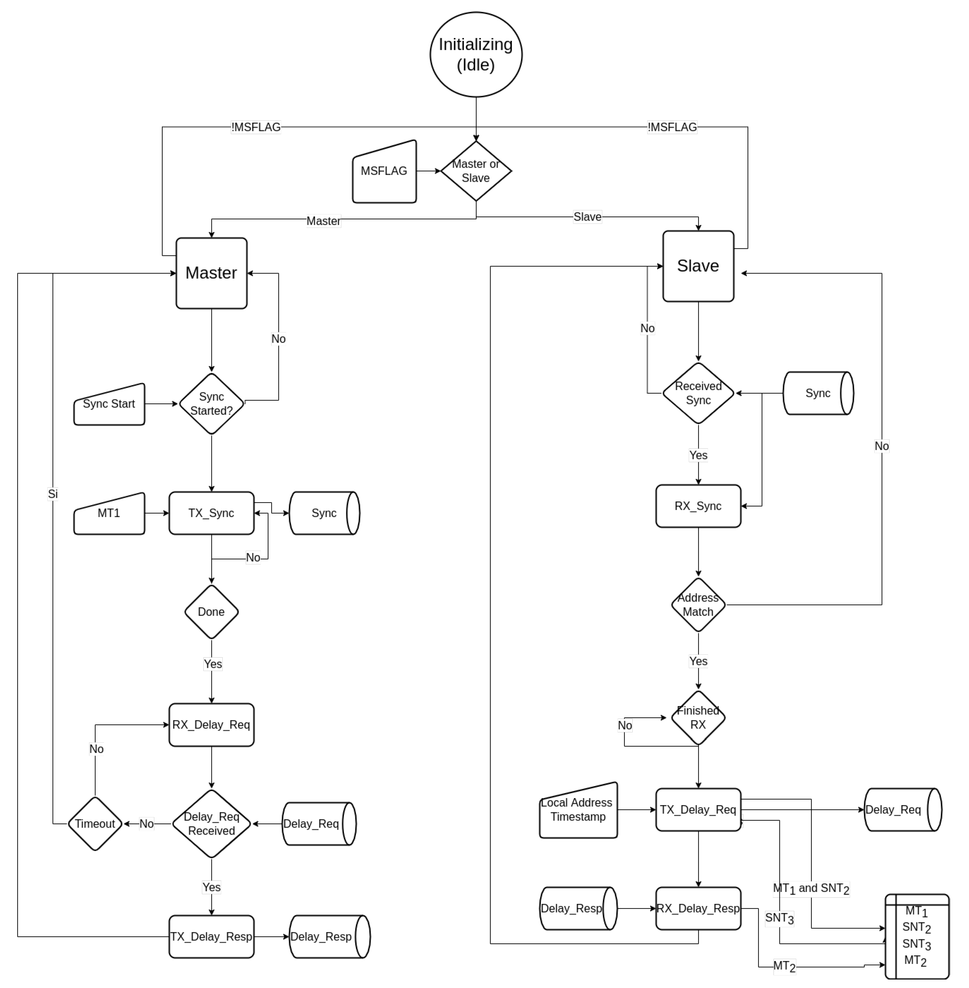
The whole process is handled by a RTL block implemented in the FPGA. This block allows for both, master and slave configuration set up by the MSFLAG port. A detailed description of the state machine implemented in Hardware Description Language (VHDL) is presented in Figure 5. At power up or enable, the block will read the MSFLAG value to determine the master or slave configuration.
On “Master” configuration, the block will be on an idle state waiting for the Sync Start flag rise to high. When this happens, a Sync message is sent to the address, ADDR. The timestamp M T 1 is stored at the falling edge of the start bit from the UART and queued to the end of the package during the transmission in the state TX_Sync. After finishing the transmission of the package, the state changes to RX_Delay_Req. In this state, the master waits for the delay request (Delay_Req) from the slave. In parallel, a timeout clock starts running in case the slave does not answer on time. If this condition is reached, the transaction is ended and the state machine goes back to idle. If the Delay_Req signal is received, the timestamp M T 2 is stored until the address is verified. After ending the transmission of the delay request, the process changes to the state TX_Delay_resp where the timestamp is packed and sent (Delay_Resp), ending the process and going back to idle.
On “Slave” configuration, the block is idle waiting for the Sync signal to be received, and when the start bit arrives, the S N T 2 timestamp is stored and kept until the address is received and verified in the state RX_Sync. In the even that the address does not match, the timestamp is dropped and the state goes back to Slave idle. If the address matches, the M T 1 timestamp is received and stored. In the state TX_Delay_Req, the slave sends a Delay_Req package, thereby capturing the S N T 3 timestamp as soon as the start bit of the UART transmission begins queuing it at the end of the package. The next state RX_Delay_Resp waits for the Delay_Resp package to read the M T 2 timestamp, completing the information needed to do the correction.
On master configuration, the corrected time (CTIME) in the master is the same as the local time and will remain unchanged during the whole process. On slave configuration, the correction happens as soon as the RX_Delay_Resp state is finished, raising a Correction Ready, CTRDY, flag high. By default CTRDY is set on low until successful synchronization.
The test circuit implemented in the FPGA consists in a 64 bits local time block incremented by a 250-MHz clock. The Simple PTP block loads a default configuration based on the “pAmp ID” that can be overridden by the Microprocessor through a Communication Block (COMBLOCK) [12]. The corrected time output from the Simple PTP feeds a Pulse Per Second (PPS) block, which changes the flank of the output each time and the corrected time reaches one second. This will be useful in measuring the time synchronization and the drift from the master’s perspective. Finally, the Simple PTP handles the HVIBNI Controller depending on the master-slave configuration and the state of the synchronization process. A block diagram of the implementation on the FPGA is shown in Figure 6.

4. Experimental Setup and Results

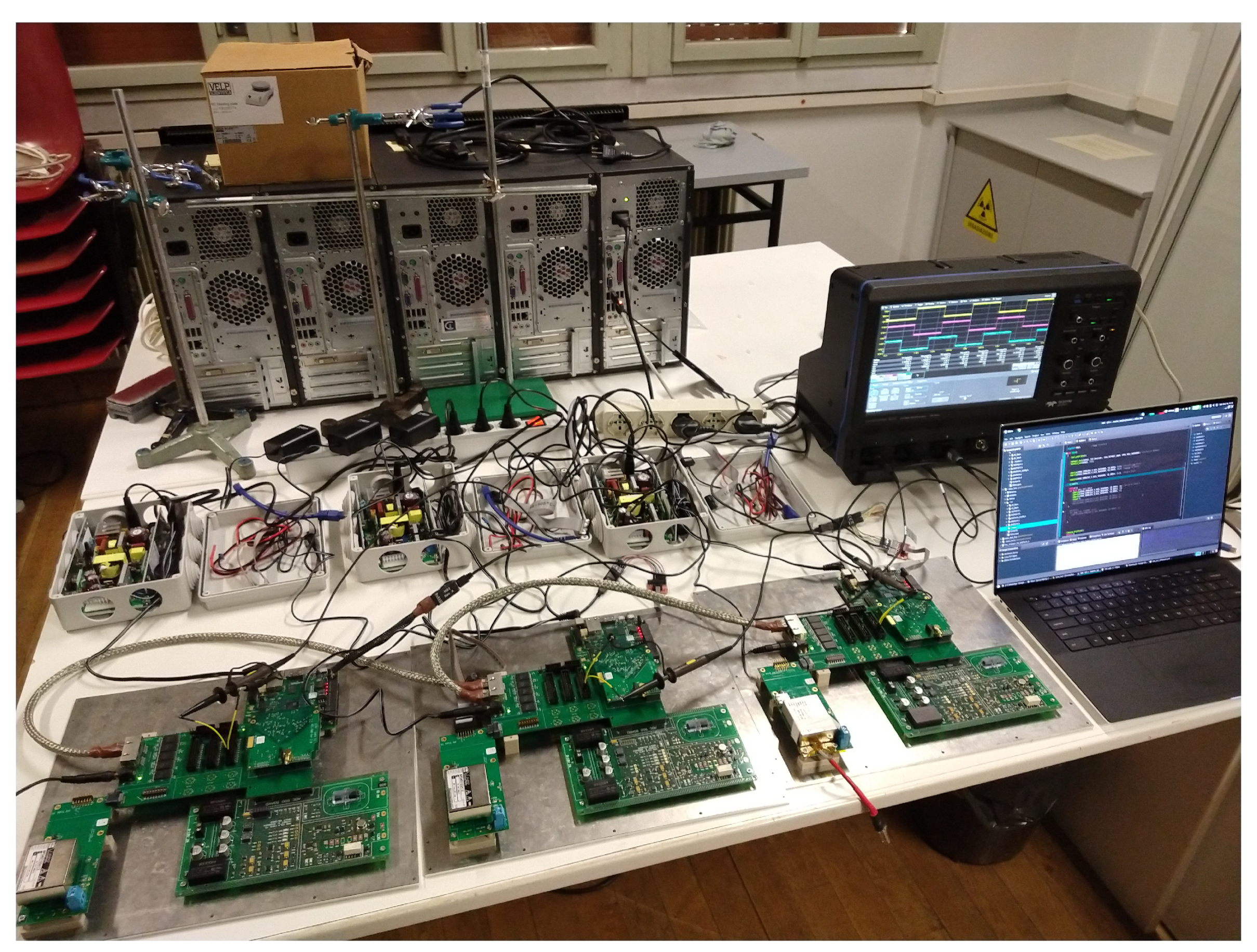
To test the protocol, three HVPSS modules were connected following the topology shown in Figure 2. The clock correction algorithm is monitored by the Xilinx Integrated Logical Analyzer (ILA) module through a Digilent JTAG-HS2 module. Each system provided a PPS signal generated by the local clock and was measured by a 20 GS/s LeCroy WaveRunner 8254 Oscilloscope to observe the synchronization and to measure the drift. The full setup is shown in Figure 7.
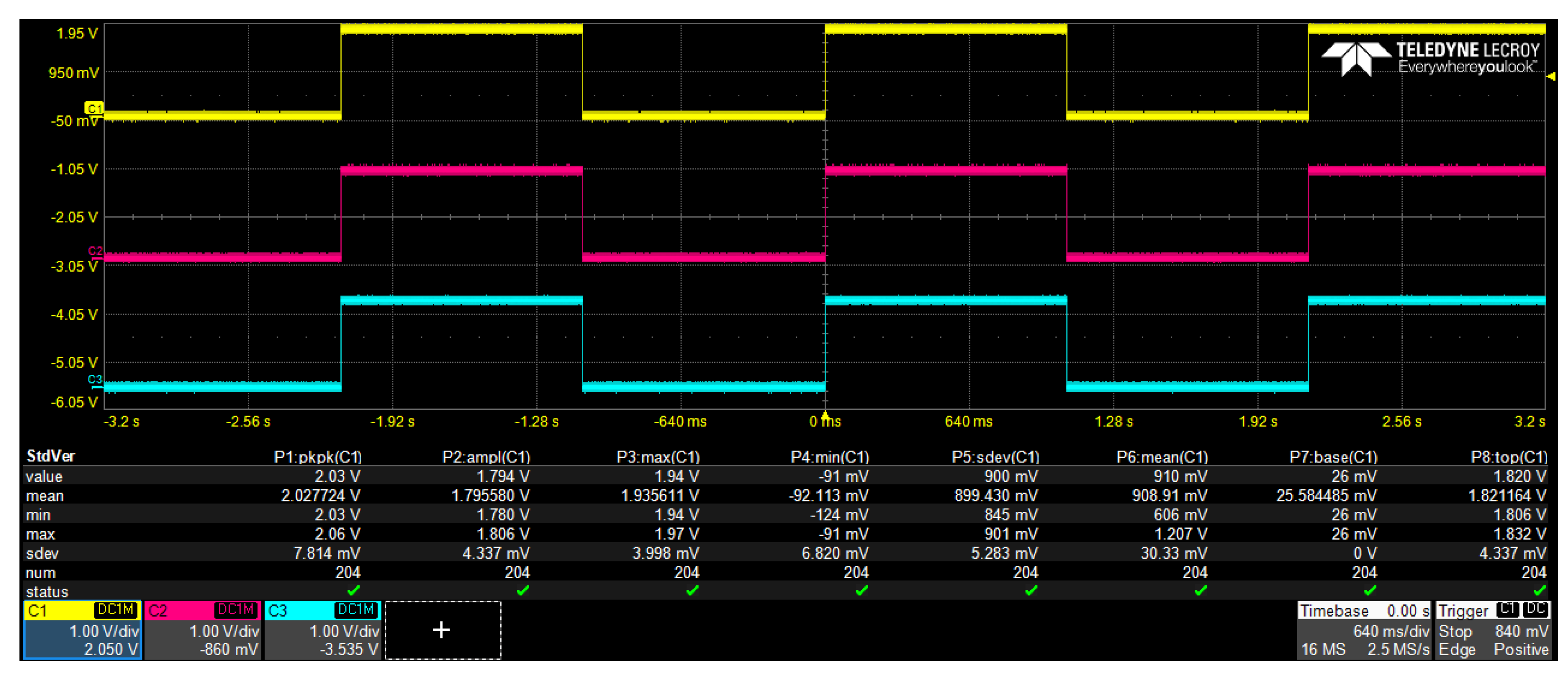
At power up, each module has a different local time as shown in Figure 8. The master clock is represented in Channel 1 of the oscilloscope (yellow), the slave 1 is represented in channel 2 (red), and the slave 2 is represented in channel 3 (blue). All the modules will synchronize to the master clock. The synchronization routine will be initialized by the microprocessor on the master HVPSS.
After the Sync signal is sent to all the slaves, the result can be appreciated in Figure 9.
Despite the synchronization, the internal clock differences between the clocks can lead to a maximum drift of 200 microseconds in 24 h as shown in Figure 10.

5. Discussion

To compensate for the drift, several sync signals need to be sent periodically, in order to keep synchronization among the modules. Nevertheless, small “jumps” have been observed during the drifts and need to be further investigated. Theoretically, the inherent error of the PTP synchronization is of two clock cycles (8 ns at 250 MHz); however, experimental observations indicate an error of 20 ns. One of the causes may be related to small delays during the calculation of Δ n (Equation (6)) plus the arithmetic operation to adjust the clock (Equation (1)) that may delay one or two extra clock cycles.
One solution may be to reduce the arithmetic operations by sending a periodical clock signal through one of the master’s reserved write buffers. Due to the fact that the transmission delay δ n is known, each master clock flank will do a fine correction to δ n to keep the system synchronized.
Another fine synchronization scheme may be achieved by adjusting the phase between the master and slave clocks as done using the White Rabbit protocol [13] in which they achieve sub-nanosecond synchronization. However, some studies need to be carried out in order to verify the effects of the HVIBNI on the phase of the clocks.
Once the previous conditions are met, the system will be used to study the propagation of discharges among electrodes. By understanding the behavior of the fast transients and its correlation with the environmental conditions, it is possible to create algorithms to predict critical events. These algorithms may give enough time to the HV power supply to set adequate voltage so as to prevent the propagation of the discharges.

6. Conclusions and Future Works

A simplified version of the Precise Time Protocol (PTP) was implemented in an FPGA through a High Voltage Isolated Bidirectional Network Interface (HVIBNI). The application achieved nanosecond time synchronization, providing galvanic isolation that sustained 2000 volts between channels. The master-slave communication is a full-duplex after the address is verified and may communicate at a stable data rate of 80 Mbps, up to 100 Mbps.
Future works may involve error verification and a re-transmission request to guarantee the integrity of the PTP transaction. Fine synchronization will be implemented to reduce the 20 ns error using the line delay ( δ n ) information or a clock phase lock in a White Rabbit protocol.
With a higher time accuracy, it may be possible to develop and implement algorithms to predict critical events using environmental conditions, compensating for the response time of current commercial HV DC-DC devices.

Author Contributions

Conceptualization, L.G.G.O. and A.C.; methodology, L.G.G.O.; software, L.G.G.O.; validation, W.O.F.S., D.D. and A.C.; formal analysis, L.G.G.O. and A.C.; investigation, L.G.G.O.; resources, M.L.C., S.L.; data curation, W.O.F.S.; writing original draft preparation, L.G.G.O.; writing—review and editing, S.L., W.O.F.S., M.L.C. and A.C.; visualization, L.G.G.O.; supervision, M.L.C. and S.C.; project administration, M.L.C. and S.C.; funding acquisition, S.C. All authors have read and agreed to the published version of the manuscript.

Funding

This research received no external funding.

Institutional Review Board Statement

Not applicable.

Informed Consent Statement

Not applicable.

Data Availability Statement

The study did not report any data.

Acknowledgments

The authors would like to acknowledge the support given by Università degli Studi di Trieste (UNITS), the Abdus Salam International Centre for Theoretical Physics (ICTP), and the Istituto Nazionale di Fisica Nucleare (INFN) Trieste branch.

Conflicts of Interest

The authors declare no conflict of interest.

Abbreviations

The following abbreviations are used in this manuscript:
CIAA-ACCComputadora Industrial Abierta Argentina
CTIMECorrection Time
CTRDYCorrection Ready
DACDigital to Analog Converter
DCDirect Current
FPGAField-Programmable Gate Array
HVHigh Voltage
HVIBNIHigh Voltage Isolated Bidirectional Network Interface
HVPSSHigh Voltage Power Supply System
ILAIntegrated Logic Analyzer
JTAGJoint Test Action Group
MICROMEGASMicro-Mesh Gaseous Structure
MLABMultidisciplinary Laboratory
MPGDMicro Pattern Gaseous Detector
MSFLAGMaster Setup Flag
MTMaster clock Time
pAmpPico-Amperometer
PCBPrinter Circuit Board
PPSPulse-Per-Second
PTPPrecise Time Protocol
RTLRegister-transfer-level
SNTSlave N clock Time
SoCSystem-on-Chip
THGEMThick Gaseous Electron Multipliers
UARTUniversal Asynchronous Receiver-Transmitter
VHDLVery High-Speed Integrated Circuit Hardware Description Language

References

  1. Sauli, F. Micro-Pattern Gaseous Detectors: Principles of Operation and Applications; World Scientific: Singapore, 2021. [Google Scholar]
  2. Chechik, R.; Breskin, A.; Shalem, C.; Mormann, D. Thick GEM-like hole multipliers: Properties and possible applications. Nucl. Instrum. Methods Phys. Res. Sect. Accel. Spectrometers Detect. Assoc. Equip. 2004, 535, 303–308. [Google Scholar] [CrossRef]
  3. Agarwala, J.; Bari, M.; Bradamante, F.; Bressan, A.; Chatterjee, C.; Cicuttin, A.; Ciliberti, P.; Crespo, M.; Torre, S.D.; Dasgupta, S.; et al. The high voltage system with pressure and temperature corrections for the novel MPGD-based photon detectors of COMPASS RICH-1. Nucl. Instrum. Methods Phys. Res. Sect. Accel. Spectrometers Detect. Assoc. Equip. 2019, 942, 162378. [Google Scholar] [CrossRef] [Green Version]
  4. Carrato, S.; Chatterjee, C.; Cicuttin, A.; Ciliberti, P.; Crespo, M.; Dalla Torre, S.; Dasgupta, S.; Florian, W.; Ordóñez, L.G.; Gobbo, B.; et al. A scalable High Voltage Power Supply System with system on chip control for Micro Pattern Gaseous Detectors. Nucl. Instrum. Methods Phys. Res. Sect. Accel. Spectrometers Detect. Assoc. Equip. 2020, 963, 163763. [Google Scholar] [CrossRef]
  5. Levorato, S. A scalable High Voltage power supply system with SoC control for Micro Pattern Gaseous Detector. In Proceedings of the 6th International Conference on Micro Pattern Gaseous Detectors, MPGD19, La Rochelle, France, 5–10 May 2019. [Google Scholar]
  6. García, L.G.; Crespo, M.L.; Carrato, S.; Cicuttin, A.; Florian, W.; Molina, R.; Valinoti, B.; Levorato, S. High Voltage Isolated Bidirectional Network Interface for SoC-FPGA Based Devices. In Applications in Electronics Pervading Industry, Environment and Society; Saponara, S., De Gloria, A., Eds.; Springer International Publishing: Cham, Switzerland, 2021; pp. 280–285. [Google Scholar]
  7. IEEE Std 1588-2019 (Revision of IEEE Std 1588-2008); IEEE Standard for a Precision Clock Synchronization Protocol for Networked Measurement and Control Systems. Institute of Electrical and Electronics Engineers: New York, NY, USA, 2020; pp. 1–499. [CrossRef]
  8. INTI. CIAA ACC Hardware User Guide. 2021. Available online: https://github.com/ciaa/CIAA_ACC/blob/master/doc/user_guide.md (accessed on 18 December 2021).
  9. ISEG. BPS Series, Small High Voltage Module for PCB Mounting Up to 4 Watt; ISEG Spezialelektronik GmbH: Radeberg, Germany, 2021. [Google Scholar]
  10. Texas Instruments. ISO782xLL High-Performance, 8000-VPK Reinforced Isolated Dual-LVDS Buffer, sllset8a ed.; Texas Instruments Incorporated: Dallas, TX, USA, 2016; Revision A. [Google Scholar]
  11. Texas Instruments. ISO7840x High-Performance, 8000-VPK Reinforced Quad-Channel Digital Isolator, sllsen2b ed.; Texas Instruments Incorporated: Dallas, TX, USA, 2015; Revision B. [Google Scholar]
  12. ICTP MLAB; INTI CMNT. The Core Comblock. 2021. Available online: https://gitlab.com/rodrigomelo9/core-comblock (accessed on 18 December 2021).
  13. Lipiński, M.; Włostowski, T.; Serrano, J.; Alvarez, P. White rabbit: A PTP application for robust sub-nanosecond synchronization. In Proceedings of the 2011 IEEE International Symposium on Precision Clock Synchronization for Measurement, Control and Communication, Munich, Germany, 12–16 September 2011; pp. 25–30. [Google Scholar] [CrossRef]
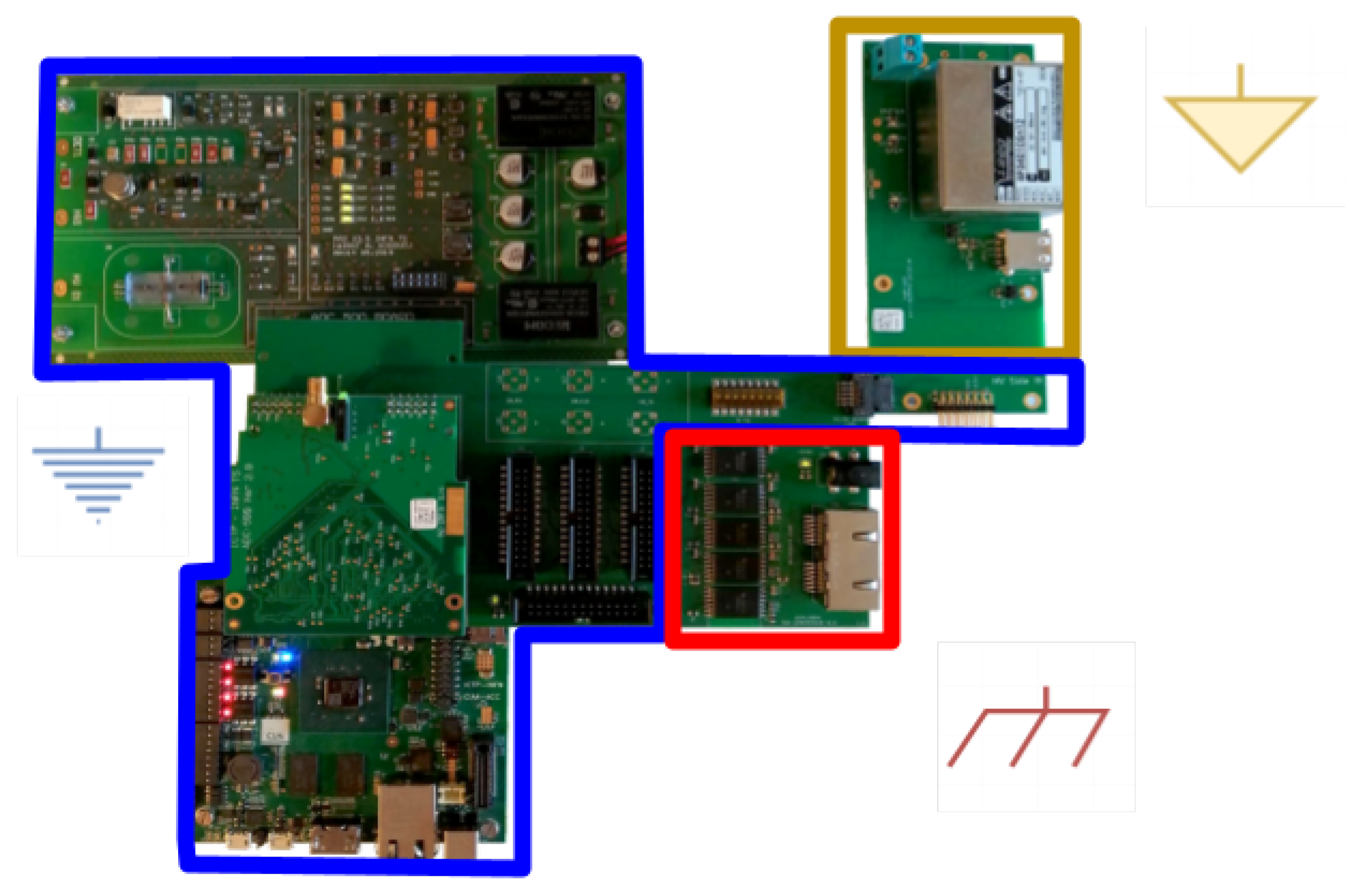
Figure 1. Different power domains in the HVPSS.
Instruments 06 00011 g001
Figure 2. Network topology for N HVPSSs.
Instruments 06 00011 g002
Figure 3. Simplified PTP principle of operation for multiple slaves.
Instruments 06 00011 g003
Figure 4. Type, Address (ADDR) and Timestamp packed for PTP transmission throug the HVIBNI.
Instruments 06 00011 g004
Figure 5. Simple PTP state diagram.
Instruments 06 00011 g005
Figure 6. Block diagram of the test circuit implemented inside the FPGA.
Instruments 06 00011 g006
Figure 7. Experimental setup.
Instruments 06 00011 g007
Figure 8. PPS signal before PTP implementation.
Instruments 06 00011 g008
Figure 9. PPS signal after PTP implementation.
Instruments 06 00011 g009
Figure 10. Time drift during synchronization.
Instruments 06 00011 g010
Publisher’s Note: MDPI stays neutral with regard to jurisdictional claims in published maps and institutional affiliations.