Project Report

Calorimetry in a Neutrino Observatory: The JUNO Experiment

by
Beatrice Jelmini
on behalf of the JUNO Collaboration
Dipartimento di Fisica e Astronomia “Galileo Galilei”, Università degli Studi di Padova & INFN Sezione di Padova, 35131 Padova, Italy
Instruments 2022, 6(3), 26; https://doi.org/10.3390/instruments6030026
Submission received: 31 July 2022 / Revised: 21 August 2022 / Accepted: 22 August 2022 / Published: 24 August 2022

Abstract

:
The Jiangmen Underground Neutrino Observatory (JUNO) is a multipurpose experiment under construction in southern China; detector completion is expected in 2023. JUNO is a homogeneous calorimeter consisting of a target mass of 20 kt of an organic liquid scintillator, aiming to detect antineutrinos from reactors to investigate the neutrino oscillation mechanism. The scintillation and Cerenkov light emitted after the interaction of antineutrinos with the liquid scintillator is seen by a compound system of 20 inch large PMTs and 3 inch small PMTs, with a total photo-coverage of 78%. A dual-calorimetry technique is developed based on the presence of the two independent photosensor systems which are characterized by different average light level regimes, resulting in different dynamic ranges. Thanks to this novel technique, an unprecedented high light yield, and in combination with a comprehensive multiple-source and multi-position calibration campaign, JUNO is expected to reach energy-related systematic uncertainties below 1% and an effective energy resolution of 3% at 1%, required for the neutrino oscillation analysis.

1. Introduction: The JUNO Experiment

The Jiangmen Underground Neutrino Observatory (JUNO) experiment [1,2] is a neutrino multipurpose experiment currently under construction in southern China; detector completion is expected in 2023.
The JUNO experiment is located about 700 m underground (1800 m.w.e) and consists of a spherical central detector (CD), surrounded by a Cerenkov water pool and surmounted by a top tracker and the calibration house, as shown in Figure 1a. The Cerenkov water pool shields the CD from environmental radioactivity and, together with the top tracker, works as an active muon veto. The CD is an acrylic 35.4   m diameter wide spherical vessel filled with 20 kt of liquid scintillator, supported by a stainless-steel latticed shell. A system of photomultiplier tubes (PMTs) is installed on the supporting latticed shell to detect the scintillation and Cerenkov light produced by (anti)neutrino interactions in the liquid scintillator. The PMT system consists of 17,612 20 inch large PMTs (LPMTs) [3] and 25,600 3 inch small PMTs (SPMTs), ensuring a total photo-coverage of 78%.
The main goal of the JUNO experiment is to probe the neutrino oscillation mechanism [4] by detecting electron antineutrinos produced in nuclear reactors, located at an average distance of 52.5 km. Figure 1b shows the non-oscillated spectrum (black line) and the oscillated spectra for the two possible neutrino mass orderings (red and blue lines), as expected to be seen by the JUNO experiment. In the first year of data taking, JUNO aims to measure three of the oscillation parameters, Δ m 31 2 , Δ m 21 2 , and sin 2 θ 12 , with unprecedented sub-percent precision [5]; furthermore, it aims to determine the neutrino mass ordering with a 3 σ significance in 6 years of data taking.
Figure 1. (a) Scheme of the JUNO detector [5]. (b) Oscillated spectra expected to be seen in JUNO for the two neutrino mass orderings (red and blue lines). The expected spectrum without neutrino oscillations is also shown (black line). An average baseline of 52.5 km and a data-taking time of 6 years were considered in the evaluation of the spectra [5].
Instruments 06 00026 g001
As can be seen from Figure 1b, a precise and accurate measurement of the antineutrino energy is essential in order to distinguish the two mass orderings. However, both the detection mechanism and the readout system introduce nonlinear biases and smearing effects that could affect the detected spectrum, thus spoiling JUNO physics potential. Consequently, an effective energy resolution of 3% at 1 MeV and energy-related systematics controlled within 1% are required. To study the detector response and meet the requirements, an extensive multiple-source and multi-position calibration strategy [6] was developed and is described in Section 2. A dual-calorimetry calibration [7,8] was also developed in order to take into account nonlinearities introduced by the readout system and is described in Section 3.
All results presented in this proceedings were obtained using JUNO official simulation software based on SNiPER [9].

2. JUNO Calibration Strategy

2.1. Detector Response: Liquid Scintillator Nonlinearity and Positional Nonuniformity

A calibration strategy [6] was developed to calibrate the liquid scintillator nonlinearity (LSNL) of the target material and the positional nonuniformity (NU), caused by the optical attenuation of light given the very large size of the JUNO detector.
There are two contributions to the energy LSNL: quenching effect and the Cerenkov light. The quenching effect is characteristic of the scintillation mechanism and is dominant in the low-energy part of the spectrum; it is usually parametrized with the semi-empirical Birks’ law. The fraction of detected primary Cereknov light is sub-dominant in JUNO, since most of the Cerenkov light is absorbed by the liquid scintillator and possibly re-emitted as secondary scintillation light; nonetheless, it needs to be considered and introduces nonlinearities at high energies.
Due to the very large size of the JUNO detector, there is a nonlinear response as a function of the position of the neutrino interaction within the liquid scintillator volume. Figure 2a shows the average number of PEs obtained by simulating 2.22 MeV gammas as a function of the distance from the detector center, R, for different polar angles θ ; the plot is representative of the positional NU of the detector response. From the figure, the value of the detected light yield at the center of the detector is Y 0 = 1345 P E / M e V [6]. The value of the detected light yield reported in this proceedings is taken from Ref. [6] and is obtained by simulating 2.22 MeV gammas at the center of the detector. The latest simulation results suggest that the detected light yield for the JUNO experiment may be about 20% higher. The reasons for the increase in the detected light yield are to be found in a higher photon detection efficiency of the PMTs [3], and updates of the PMT optical model [10] and the central detector geometry [11] in the JUNO official simulation software. For increasing radius R, an increase in the detected light yield is observed, reaching a maximum towards the edge of the detector and eventually dropping due to leakage effect and internal total reflection effect at the detector boundary. The increase in the region between 6 and 15 m is due to a combination of the optical attenuation of photons propagating through the detector, which follows an exponential law, and the variation in the active photon coverage [6].

2.2. Multiple-Source and Multi-Position Calibration Campaign

To calibrate the LSNL, several radioactive sources are needed to cover the energy range of interest for the neutrino oscillation analysis.
We plan to deploy the following gamma sources: 137Cs ( 0.662 MeV g γ ), 54Mn ( 0.835 MeV g γ ), 60Co (1.173+ 1.333 γ ), and 40K ( 1.461 MeV g γ ). A positron source, 68Ge, will also be used to have two low-energy 0.511 MeV gamma-rays. We also plan to deploy two neutron sources, AmBe and AmC, which will provide higher energy gamma-rays ( 4.43 MeV and 6.13 MeV, respectively) and neutrons, which will then be captured by hydrogen nuclei, thus producing a 2.22 MeV gamma, or by 12C nuclei, producing one 4.94 MeV gamma-ray or a 3.68 MeV and a 1.26 MeV gamma-ray. The continuous spectrum of a cosmogenic background, 12B, will be used to cover the high-energy part of the reactor spectrum, thus allowing full coverage of the energy range of interest.
Results based on the full JUNO simulation are shown in Figure 2b. The black points represent simulated data, showing the peaks corresponding to the various radioactive sources listed above. The red line is the best fit curve obtained by using a Daya Bay model based on a four-parameter function [12]:
E vis E true = p 0 + p 3 / E true 1 + p 1 e p 2 E true .
The Daya Bay model used in the fit can properly describe the LSNL, with a residual bias between simulated data and the best fit curve less than 0.2%.
To calibrate the positional NU, radioactive sources will be deployed in several positions in the whole liquid scintillator volume, thanks to a robust and flexible calibration hardware. The calibration hardware [6] is located in the calibration house above the central detector, as shown in Figure 1a, and consists of several independent subsystems, as shown in Figure 3a.
The automatic calibration unit (ACU) was developed to calibrate the detector along the central vertical axis z; the positioning of the source along the z axis is expected with a precision better than 1 c m . Due to its simplicity and robustness, we plan to use the ACU to frequently deploy several sources and monitor the stability of the energy scale during data-taking.
The guide tube system (GT) consists of a tube looped outside of the acrylic sphere containing the liquid scintillator along a longitudinal circle; a positioning precision of 3 c m is expected for this system. The GT system was developed to calibrate the CD nonuniformity at the boundary.
We also plan to use two cable loop systems (CLSs) to deploy sources to off-axis positions; the two systems will be installed in two opposite half-planes. An independent ultrasonic system is employed to position the sources with a precision of 3 c m .
Finally, a remotely operated vehicle (ROV) will deploy a radioactive source almost anywhere in the CD volume with a precision of 3 c m . The ROV serves as a supplemental system to the ACU, GT, and CLSs, and will be used to study local effects or azimuthal dependence where the CLSs cannot provide sufficient information.
An extensive study [6] was performed to find the optimal set of calibration points which minimizes the effective energy resolution, Equation (3), introduced in the next section. Figure 3b shows an optimal set of 250 random calibration points in a half vertical plane of the JUNO CD that can be used to correct the detector nonuniformity.

2.3. Energy Resolution

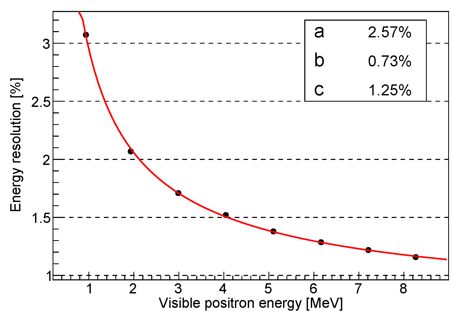
The energy resolution is parametrized with the following standard equation:
σ E E = a E 2 + b 2 + c E 2 .
The term a is the stochastic term, dominated by the statistical fluctuations in the emission of optical photons and subsequent detection on the PMT photocathode, thus being related to the total light yield value. b is the constant term which is dominated by the positional NU and can be controlled thanks to the multi-position calibration campaign presented in Section 2.2. The last term, c, is dominated by the contribution of the dark noise from the PMTs. Results from the full MC simulation are shown in Figure 4.
In JUNO, we usually express the energy resolution in terms of an effective resolution term:
a ˜ a 2 + b × 1.6 2 + c 1.6 2 .
The factors 1.6 and 1/1.6 reflect the fact that the second term is not improving with the visible energy, and that the third term declines quickly with the energy [6]. From the most recent simulation, a ˜ is found to be less than 3%, thus meeting the requirements for the reactor antineutrino spectrum analysis.

3. Dual-Calorimetry Calibration

Large PMTs are expected to cover a wide dynamic range, from 0 to 100 photoelectrons, and perform charge measurement through charge integration. The charge integration relies on the sampling of the waveform, which is performed by the front-end and read-out large PMT electronics [2] located underwater near the PMTs and equipped with 14 bit 1 G Hz flash analog-to-digital converters (ADCs). Both the PMTs and the readout electronics could introduce additional instrumental nonlinearities, which could in principle be different from channel to channel.
A dual-calorimetry calibration (DCC) [7,8] was developed to correct the large-PMT channel-level nonlinearity and relies on the additional small-PMT system. Small PMTs are placed between large PMTs and, given their small size, they mainly work in the single-photoelectron regime, allowing charge measurement through photoelectron counting. Thus, with good approximation, they constitute a linear system which can be used as an in-detector reference for the large-PMT system.
The DCC can be performed by using a tunable ultraviolet light source covering the full range of the reactor spectrum and by comparing the channel-level large-PMT response to the response of the small-PMT system. The response can be factorized into three terms, as follows [8]:
R L channel = R LSNL · R NU L · R QNL L ;
R S system = R LSNL · R NU S · R QNL S ,
where the superscripts L and S stand for large PMT and small PMT, respectively.
R LSNL is the term related to the LS nonlinearity, which is the same for both systems since they are exposed to the same event, hence the same energy deposition. R NU L / S is the term describing the positional nonuniformity, which in principle can be different for the two PMT systems. The UV source will be located at the center of the detector; given the fixed location of the source, the nonuniformity terms are constants, thus can be factorized out. Finally, R QNL L / S is the term related to the charge nonlinearity.
In the end, if we compare the response of the large-PMT channel and small-PMT system we are left with the terms related to the charge response:
R L channel R S system = R QNL L R QNL S .
Figure 5 shows an example of the application of the DCC technique at event level, where large-PMT channel-level nonlinearities are corrected. The dotted black line represents the ideal case with zero instrumental nonlinearity. The solid red line represents a 2% event-level instrumental nonlinearity originated by assuming an extreme scenario, with 50% channel-level nonlinearity in the 0 to 100 photoelecton range. The dashed blue line shows the corrected instrumental nonlinearity obtained after the application of the channel-wise DCC technique: the instrumental nonlinearity is reduced to <0.3%.

4. Conclusions

The JUNO experiment is expected to reach a precise and accurate measurement of the antineutrino energy for the neutrino oscillation analysis. This result will be achieved thanks to a multiple-source and multi-position calibration system to correct the liquid scintillator nonlinearity and the positional nonuniformity. A dual-calorimetry calibration technique will also be used to correct large-PMT channel-level nonlinearity by using the small-PMT system as an in-detector linear reference.

Funding

This research received no external funding.

Data Availability Statement

Not applicable.

Conflicts of Interest

The author declares no conflict of interest.

Abbreviations

The following abbreviations are used in this manuscript:
ACUAutomatic calibration unit
CDCentral detector
CLSCable loop system
DDCDual-calorimetry calibration
GTGuide Tube
JUNOJiangmen Underground Neutrino Observatory
LSNLLiquid scintillator nonlinearity
NUNonuniformity
PMTPhotomultiplier tube
QNLCharge nonlinearity
ROVRemotely operated vehicle

References

  1. An, F.; An, G.; An, Q.; Antonelli, V.; Baussan, E.; Beacom, J.; Bezrukov, L.; Blyth, S.; Brugnera, R.; Buizza Avanzini, M.; et al. Neutrino Physics with JUNO. J. Phys. G Nucl. Part. Phys. 2016, 43, 30401. [Google Scholar] [CrossRef]
  2. The JUNO Collaboration. JUNO physics and detector. Prog. Part. Nucl. Phys. 2022, 123, 103927. [Google Scholar] [CrossRef]
  3. The JUNO Collaboration; Abusleme, A.; Adam, T.; Ahmad, S.; Ahmed, R.; Aiello, S.; Akram, M.; An, F.; An, G.; An, Q.; et al. Mass Testing and Characterization of 20-inch PMTs for JUNO. Eur. Phys. J. C 2022, submitted. arXiv:https://arxiv.org/abs/2205.08629. [Google Scholar]
  4. Workman, R.L.; Burkert, V.D.; Crede, V.; Klempt, E.; Thoma, U.; Tiator, L.; Agashe, K.; Aielli, G.; Allanach, B.C.; Amsler, C.; et al. Review of Particle Physics. Prog. Theor. Exp. Phys. 2022, 83C01. [Google Scholar]
  5. The JUNO Collaboration; Abusleme, A.; Adam, T.; Ahmad, S.; Ahmed, R.; Aiello, S.; Akram, M.; An, F.; An, G.; An, Q.; et al. Sub-percent Precision Measurement of Neutrino Oscillation Parameters with JUNO. Chin. Phys. C submitted. 2022, arXiv:https://arxiv.org/abs/2204.13249. [Google Scholar]
  6. The JUNO Collaboration; Abusleme, A.; Adam, T.; Ahmad, S.; Ahmed, R.; Aiello, S.; Akram, M.; An, F.; An, G.; An, Q.; et al. Calibration strategy of the JUNO experiment. J. High Energ. Phys. 2021, 4, 1–33. [Google Scholar] [CrossRef]
  7. He, M. Double Calorimetry System in JUNO. In Proceedings of the TIPP 2017, Beijing, China, 22 May 2022. [Google Scholar] [CrossRef]
  8. Han, Y. Dual Calorimetry for High Precision Neutrino Oscillation Measurement at JUNO Experiment. Ph.D. Thesis, Université de Paris, Paris, France, 2020. [Google Scholar]
  9. Lin, T.; Zou, J.; Li, W.; Deng, Z.; Fang, X.; Cao, G.; Huang, X.; You, Z.; On Behalf of the JUNO Collaboration. The Application of SNiPER to the JUNO Simulation. J. Phys. Conf. Ser. 2017, 898, 42029. [Google Scholar] [CrossRef]
  10. Wang, Y.G.; Cao, G.; Wen, L.; Wang, Y.F. A new optical model for photomultiplier tubes. Eur. Phys. J. C 2022, 82, 1–14. [Google Scholar] [CrossRef]
  11. Zhi, W. The Central Detector of JUNO. In Proceedings of the Neutrino 2022 Virtual Conference, Seoul, Korea, 30 May 2022. [Google Scholar] [CrossRef]
  12. An, F.P.; Balantekin, A.B.; Band, H.R.; Beriguete, W.; Bishai, M.; Blyth, S.; Rosero, R. Spectral measurement of electron antineutrino oscillation amplitude and frequency at Daya Bay. Phys. Rev. Lett. 2014, 112, 61801. [Google Scholar] [CrossRef] [PubMed] [Green Version]
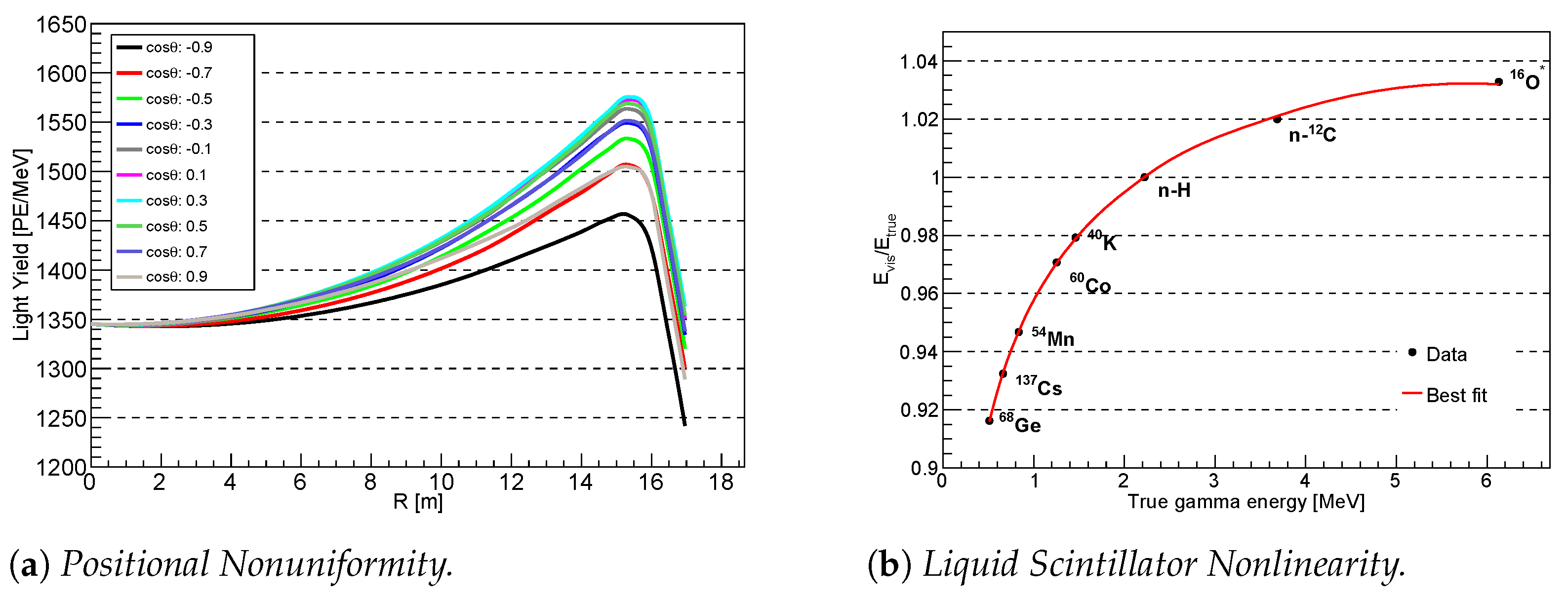
Figure 2. (a) Expected light yield in JUNO as a function of the distance from the detector center, showing the positional nonuniformity of the detector response; different lines refer to different polar angles, highlighting a difference between the upper and lower hemispheres [6]. (b) Liquid scintillator nonlinearity expected for the JUNO experiment due to the quenching effect and Cereknov light contribution. Black points represent simulated data, while the red line is the best fit line; see text for more details [6].
Instruments 06 00026 g002
Figure 3. (a) Overview of the calibration hardware for the JUNO experiment. See text for details on the individual subsystems [6]. (b) An optimal set of 250 random calibration points in a half vertical plane of the JUNO CD needed to properly correct the position nonuniformity of the response [6].
Instruments 06 00026 g003
Figure 4. Energy resolution expected for the JUNO experiment obtained by full MC simulation of positrons at different energies. The red line is the best fit curve obtained by using Equation (2). Best fit values for the three parameters are shown in the box [6].
Instruments 06 00026 g004
Figure 5. Example of the application of the dual-calorimetry calibration technique [6,8]. The solid red line shows an extreme scenario of a 50% channel-level nonlinearity resulting in a 2% event-level nonlinearity; the dashed blue line represents the same scenario after applying the channel-level correction, resulting in a residual <3% event-level nonlinearity.
Instruments 06 00026 g005
Publisher’s Note: MDPI stays neutral with regard to jurisdictional claims in published maps and institutional affiliations.