Article

Measuring the Beam Energy in Proton Therapy Facilities Using ATLAS IBL Pixel Detectors

by
Isabelle Schilling
1,*,†,
Claus Maximilian Bäcker
1,2,3,4,
Christian Bäumer
1,2,3,4,5,
Carina Behrends
1,2,3,4,
Marius Hötting
1,
Jana Hohmann
1,
Kevin Kröninger
1,
Beate Timmermann
2,3,4,5,6 and
Jens Weingarten
1
1
Department of Physics, TU Dortmund University, 44221 Dortmund, Germany
2
West German Proton Therapy Center Essen (WPE), West German Cancer Center (WTZ), 45147 Essen, Germany
3
West German Cancer Center, 45122 Essen, Germany
4
University Hospital Essen, 45147 Essen, Germany
5
German Cancer Consortium, 45147 Essen, Germany
6
Clinic for Particle Therapy, University Hospital Essen, 45122 Essen, Germany
*
Author to whom correspondence should be addressed.
Current address: Department of Physics, TU Dortmund University, Otto-Hahn-Straße 4a, 44221 Dortmund, Germany.
Instruments 2022, 6(4), 80; https://doi.org/10.3390/instruments6040080
Submission received: 30 September 2022 / Revised: 22 November 2022 / Accepted: 24 November 2022 / Published: 29 November 2022
(This article belongs to the Special Issue Medical Applications of Particle Physics)

Abstract

:
The accurate measurement of the beam range in the frame of quality assurance (QA) is a requirement for clinical use of a proton therapy machine. Conventionally used detectors mostly estimate the range by measuring the depth dose distribution of the protons. In this paper, we use pixel detectors designed for individual particle tracking in the high-radiation environment of the ATLAS experiment at LHC. The detector measures the deposited energy in the sensor for individual protons. Due to the limited dynamic energy range of the readout chip, several ways to measure the proton energy or range are examined. A staircase phantom is placed on the detector to perform an energy calibration relative to the NIST PSTAR stopping power database. In addition, track length measurements are performed using the detector aligned parallel with the beam axis to investigate the Linear Energy Transfer (LET) per pixel along the trajectory of individual protons. In this proof-of-principle study, we show that this radiation hardness detector can successfully be used to determine the initial proton energy for protons impinging on the sensor with an energy below 44 MeV after the range shifters. It becomes clear that an improvement of the energy resolution of the readout chip is required for clinical use.

1. Introduction

Comprehensive guidelines for the quality assurance (QA) of proton therapy delivery have been defined by the AAPM task group 224 [1]. According to these guidelines, the deviation of the proton range as an indicator for the proton energy has to be less than 1 mm.
Particle-counting hybrid silicon detectors such as the MiniPix-Timepix have been used to successfully estimate the incident proton range or energy using the LET spectra of protons in thin silicon sensors at clinically relevant energy ranges in previous studies [2,3,4]. Furthermore, other studies show promising results for measuring the beam energy of clinical proton beams with a time-of-flight system constructed from silicon sensors developed for High-Energy Physics (HEP) applications [5].
In this study, we use ATLAS IBL tracking detectors [6] designed for HEP experiments at CERN. The detectors are specifically designed to be very radiation tolerant, with an expected total ionizing dose over the lifetime of the ATLAS experiment of 2.5 MGy. Being designed as tracking detectors, they feature high spatial resolution and single particle counting, as well as providing information on the deposited energy in the sensor. The usage and applicability of this detector system for the tracking of charged particles is well understood and constantly improved by the HEP community. Therefore, the aim of this study is to test if the IBL readout chip designed for efficient single-particle tracking and high radiation hardness can be used for proton kinetic energy measurements with an energy resolution sufficient for the QA of proton therapy facilities.
As a combined measurement of the spot size, dose linearity, and range of the protons would simplify the clinical QA workflow [7], the first part of this study focuses on proof-of-principle measurements demonstrating the capability of the ATLAS IBL tracking detector to determine the proton range and energy by measuring the LET spectra of protons at normal incidence to the sensor, referred to as LET spectra measurements.
Conventionally used detectors such as the Multi-Layer Ionization Chamber (MLIC) Giraffe detector (IBA Dosimetry, Schwarzenbruck, Germany) estimate the range by measuring the depth dose distribution of the protons [8], whereas hybrid pixelated semiconductor detectors such as the Timepix or the Medipix detector measure the energy loss of particles along the way through the detector [9,10,11]. In order to take advantage of the small pixel size, the particle-counting ATLAS pixelated semiconductor detector is aligned parallel with the beam axis, tracking the deposited energy in the sensor for individual protons, thereby allowing the determination of the LET along the track in 50 μm silicon pixels. Therefore, the second part of this paper presents proof-of-principle measurements to evaluate the applicability of the device under study for measurements of the proton energy/range by means of the LET curve in silicon, termed track LET measurements.
The ability of energy determination as an additional usage besides the shape and position measurements can highlight a further application of hybrid semiconductor detectors as QA devices in proton therapy.

2. Materials and Methods

2.1. ATLAS IBL Pixel Detector

The ATLAS IBL pixel detector is designed to track high-energy particles in the ATLAS experiment at CERN [6]. It is a hybrid pixelated detector consisting of a 200   μ m -thick n-in-p silicon sensor segmented into 80 × 336 pixels with a size of ( 250 × 50 ) μm2 and an FE-I4B readout chip bump bonded pixelwise [12]. The hit efficiency of the detector for individual protons reaches up to 99.9% [13].
In silicon, an average energy deposit of 3.6 eV is needed to create an electron–hole pair [14]. The readout chip provides information on the generated charge using the Time over Threshold (ToT) method with a resolution of 4 bits. The gain of the amplifier can be adjusted for every single pixel in a process referred to as tuning. Therefore, the calibration of the ToT values has to be performed individually for each pixel for any given tuning.
Each pixel contains a discriminator for zero suppression. The discriminator threshold is also tuned individually for each pixel and, together with the amplifier gain, determines the dynamic range of the available ToT values. For the following measurements, the gain and threshold tuning yielded a dynamic range for the deposited energy of (139–678) keV, which is close to the maximum charge the readout chip can process. The tuning was chosen to accommodate the energy deposition of proton energies impinging on the sensor described in Section 2.3. Due to the smaller path length of 50 μm of the protons through the pixel when measuring parallel with the beam direction, an adapted tuning resulting in a dynamic deposited energy range of the detector of (67–372) keV is used during the second measurement campaign.
Since the readout chip was developed for operation in the ATLAS experiment, in which the particles pass through the detector at a frequency of 40 MHz due to the spill structure of the Large Hadron Collider beam, the chip is operated at the same frequency.
For data acquisition, an external trigger signal is generated. The internal storage of the readout chip allows it to be triggered up to 16 times in a row, providing a maximum sensitive window of 400 ns, allowing small deposited charges, which are delayed due to the fixed peaking time of the amplifier circuit (time walk), to be detected. As a compromise between the maximum sampling rate of the proton beam (high particle fluxes up to 10 10 cm 2   s 1 in proton therapy [15]) and memory consumption of the readout system for the detector in the following measurements, trigger signals of varying duration were issued at a fixed frequency of 1 kHz.

2.2. Beam Characteristics

Measurements of the LET spectra were performed at a clinical Pencil Beam Scanning (PBS) line equipped with a dedicated PBS nozzle (ProteusPlus system, IBA PT, Louvain-la-Neuve, Belgium), based on an IBA Proteus 235 isochronous cyclotron that delivers protons with energies in the range of (100–228) MeV at a rate of 106 MHz [16]. Scanned homogeneous fields larger than the detector area at the lowest possible proton energy were used during the measurements.
Based on the range measurements for a nominal beam energy of 100 MeV, the delivered proton energy is between 99.7 MeV and 100.5 MeV depending on the tables used to convert the measured range into proton energy [17]. Using the center of this interval, we assumed the delivered proton energy to be ( 99.91 ± 0.40 ) MeV. The variation of the proton energy is stated in the same paper to be 0.65 MeV.
As the orientation of the detector with respect to the beam is crucial for the various measurements, we define the incidence angle β with respect to the normal of the detectors surface as shown in Figure 1.
According to the clinical beam model used at the treatment center, the beam divergence for the proton energies used for theses measurements is approximately 0.3 and can be neglected.
To vary the energy of the protons incident on the detector during both measurement campaigns, different range shifters and a variable number of RW3 slabs (type SP34 IBA Dosimetry, composition: 98% polystyrene + 2% TiO 2 , water-equivalent ratio WER = 1.025 ) were placed in front of the nozzles.

2.3. Experimental Setup

Throughout the publication, we will refer to proton energies at various stages. To avoid confusion, Figure 2 illustrates the definitions:
  • E init : initial proton energy delivered by the accelerator;
  • E phantom : proton energy downstream of the variable thickness of RW3 slabs;
  • E sensor : proton energy incident on the silicon sensor.
During the LET spectra measurement, the pixel detector was mounted on the treatment table in the isocenter of the beam perpendicular to the beam direction ( β = 0 ). To measure the energy deposition in the sensor for different proton energies in a single measurement, three types of custom-made Poly(Methyl Methacrylate) (PMMA) staircase phantoms were placed upstream of the detector. One of the phantoms is shown in Figure 3.
The phantoms differ in the number of blocks, between two and nine, with physical thicknesses between 10.0 mm and 26.0 mm. The energy of the protons impinging on the sensor is therefore between 12.1 MeV and 52.7 MeV. The WER of the PMMA was measured using a MLIC Giraffe detector (IBA Dosimetry, Schwarzenbruck, Germany) to be W E R PMMA = 1.16 ± 0.02 . The uncertainty analysis of W E R PMMA is based on the work of Behrends et al. [18]. Two measurements each, using RW3 slabs with physical thicknesses of 4.0 cm and 4.4 cm, respectively, were performed.
As a first result, the two-dimensional map of the mean deposited energy in the silicon sensor is shown in Figure 4, measured with 4.0 cm RW3 slabs upstream of the staircase phantom and an energy of E phantom 65.4 MeV, respectively. The dotted block in the picture highlights a thicker phantom step than the straight lines’ block, resulting in higher deposited energy in this area of the sensor. Differences in the deposited energy downstream of the blocks for the 9-step phantom can be seen.
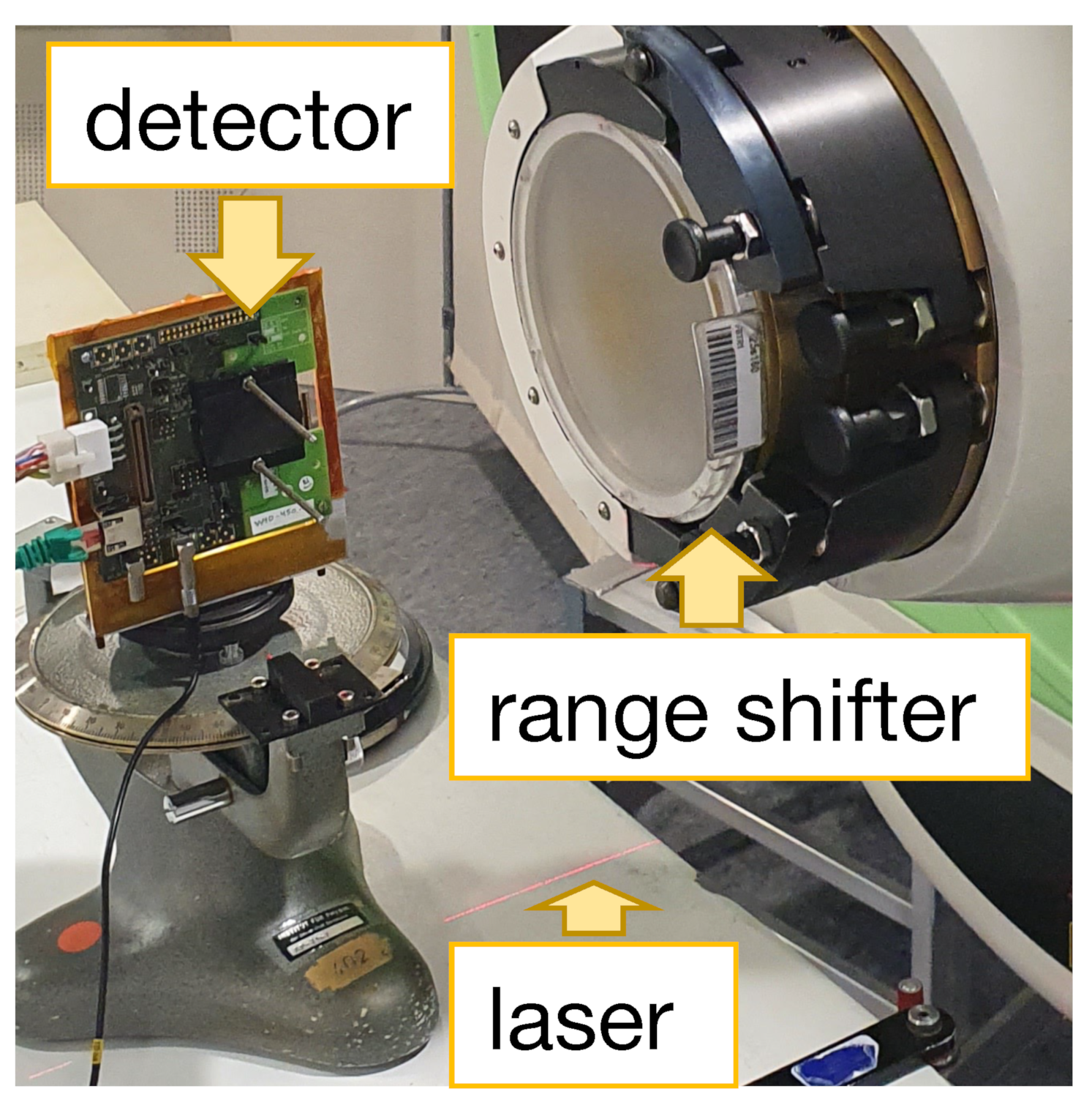
In order to determine the energy of the protons by means of the LET along their trajectory in the silicon sensor, the detector was mounted on a goniometer standing on the treatment table. Using the laser positioning system integrated into the treatment room, the detector is manually aligned parallel with the beam axis ( β = ( 90 ± 0 . 5 )), with the smaller pixel side (rows) oriented in the beam direction, as shown in Figure 5. The protons traverse the detector parallel with its surface. These measurements are referred to as track LET measurements. A photo of the setup is shown in Figure 6.
By using different thicknesses of the range shifters and RW3 slabs, measurements with five different proton energies varying between E sensor 54.6 MeV and E sensor 16.6 MeV were performed. These values of the proton energy were selected to evaluate the path of the protons through the sensor for particles with a Continuous Slowing Down Approximation (CSDA) range in silicon smaller than the length of the detector ( 1.68 cm) so that they are stopped completely in the detector.

2.3.1. Clustering and Cluster Charge

Due to the lateral diffusion of the charge cloud in the sensor, a single proton can deposit energy in more than one pixel (charge sharing) [19]. In order to assign the correct energy deposition for each passing proton, simultaneous hits in neighboring pixels are combined into a cluster in software. To account for slight differences in the ToT calibration between pixels in a cluster, the ToT information in all pixels is converted into deposited energy and then summed up.
These measurements were performed with the smallest possible sensitive time per trigger event of 25 ns to avoid exceeding the storage capability of the readout system. Thus, no temporal coincidence criterion is needed for clustering. The mean cluster size for single protons depends on their energy since the LET increases for lower-energy protons, resulting in an increased mean cluster size [19]. Due to the small incidence angle of β 0 and the large pixel size, by far, most of the protons deposit their energy in one or two pixels. The mean percentage of clusters consisting of more than 2 pixels over all measured energies is only 1%. Therefore, the size or shape of clusters cannot be used to estimate the real incidence angle for each proton, as has been done in other studies [20].

2.3.2. Regions of Interest

For the analysis of the LET spectra measurements, the Regions Of Interest (ROIs) are defined, which represent the positions of the phantom blocks on the sensor. Protons hitting pixels within an ROI are assumed to have traversed the same amount of material in the staircase phantom and, therefore, to have the same energy remaining E sensor . The ROIs are selected to exclude the edges of the blocks of the phantom to avoid the influence of scattered protons with different energies coming from other phantom blocks.

2.4. Let Spectra Measurement

When analyzing the measured energy deposition d E per track length d l in thin detectors, it is common to use an approximation in which the measured energy deposition is taken as the theoretically calculated L E T [21]:
L E T = d E d l .
This approximation is based on the definition of the LET as the mean of the unrestricted dE/dx distribution defined by the Particle Data Group [22], which assumes the LET to be constant over the thickness of thin detectors.
The incidence angle of the protons for this study is β 0 , with an uncertainty due to manual alignment of 0.5 and a negligible beam divergence. Geant4 simulations were performed to determine the width of the angle distribution due to scattering in the RW3 plates. The maximum spread, defined as twice the standard deviation of the scattering angle distribution, containing nearly 86.5% of all protons, for the largest thickness of the RW3 plates, was found to be 6°. The maximum track length in the detector, d l = t cos β , deviates from the detector thickness by only 0.5 %. Therefore, we approximated the track length to be equal to the detector thickness of t   =   200 μm.
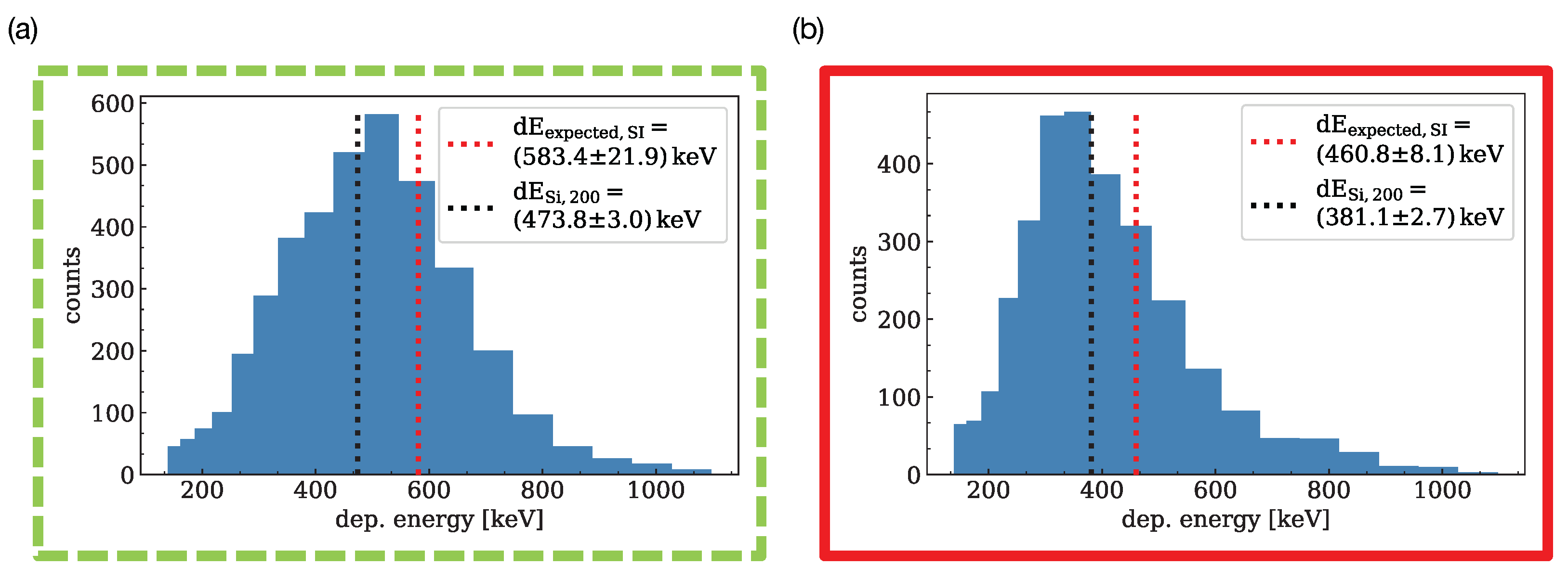
The output of each measurement is a histogram of the deposited energy per cluster. Figure 7 shows the histograms for the ROIs highlighted in Figure 4, where the phantom thicknesses are 2.0 cm ( E sensor 36.8 MeV ) and 1.2 cm ( E sensor 49.8 MeV ), respectively. The centers and widths of the bins were chosen to accommodate the non-linearity of the calibration of the ToT values.
Due to a number of detector effects arising from the tuning of the threshold and gain of the individual readout channels, the deposited energy is systematically underestimated by a constant amount, as shown in Figure 7. Therefore, we decided to use the arithmetic mean of the histogram as an estimator for the LET in 200 μm silicon. We will refer to this quantity as d E Si , 200 .
To use the mean energy deposition per proton to determine the proton energy d E Si , 200 , it has to be calibrated to the energy of the incident proton E sensor . Therefore, we used the initial proton energy from the accelerator E init and subtracted the energy deposited in the RW3 plates and the respective region of the staircase phantom to determine E sensor . Using the stopping power for protons in silicon according to the PSTAR database [23], we estimated the expected deposited energy in 200 μm silicon d E expected , SI . This process is shown in Figure 8. The energy-dependent conversion between stopping power in water and in silicon using the PSTAR dataset was implemented successfully in another work before [24].
We considered two main sources of uncertainties for the calibration: that on the estimator d E SI , 200 and the systematic uncertainty of the expected value of the energy deposition d E expected , SI .
The uncertainty of the estimator d E SI , 200 comprises the spread of the deposited energy, quantified by the standard error of the mean value σ stat . , as well as the influence of slight differences of the tuning of the individual pixels. To estimate the inhomogeneity of the pixel response, which we will refer to as σ tune , the detector was irradiated with a homogeneous field with a constant energy. The mean relative standard deviation σ tune d E SI , 200 = 1.12% for the different regions was used to estimate the corresponding type B uncertainty of d E SI , 200 . This results in a total uncertainty of the estimator of σ dE , SI = σ stat . 2 + σ tun . 2 .
The uncertainty of the expected energy deposition d E expected , SI is dominated by that on the energy of the protons hitting the sensor σ ( E sensor ) , which comprises the uncertainties on the initial proton energy and the straggling in the RW3 slabs and staircase phantom. Monte Carlo simulations showed that the impact of straggling is negligible compared to the impact of the uncertainty of the initial proton energy of σ ( E init ) = 0.4 MeV [17]. The spread of the initial proton energy influences the deposited energy and is therefore already taken into account in the statistical uncertainty of d E expected , SI .
Furthermore, the uncertainty of the physical thickness of the RW3 slabs ( σ ( t RW 3 ) = 0.1 mm [25]) and the staircase phantom need to be taken into account. The latter is calculated from the uncertainty of the physical thickness of the phantom ( σ t = 0.1 mm) and that of the WER of the PMMA ( σ WER = 0.02 ).
As the largest possible W E T stair subtracted from the smallest possible initial energy E init yields the lower limit of the expected energy of the proton hitting the sensor, E sensor , and vice versa, this calculation is used for a conservative estimation of the uncertainty of the expected value of the energy deposition.
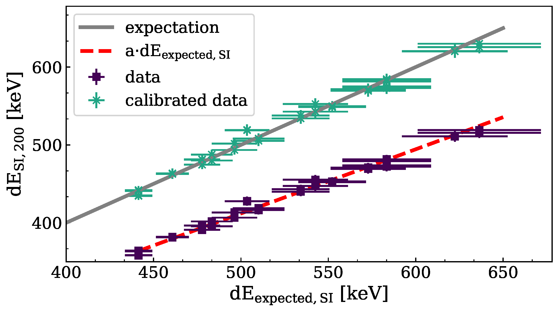
We used the NIST stopping power database to calculate the expected energy deposition [23]. The square purple data points in Figure 9 show a clear correlation between the measured mean deposited energy d E SI , 200 using the staircase phantom and the expected energy deposition d E expected , SI , even if the measurement systematically underestimates the true deposited energy. A parameter a is used to linearly scale the measured data to agree with the expected energy deposition. The uncertainty of the scaled measurement data, which we will refer to as d E SI , 200 , cal , is determined using Gaussian error propagation.
σ dE , SI , 200 , cal . = σ dE , sensor a 2 + d E SI , 200 a 2 · σ a 2 .
The starred green data points in Figure 9 show the scaled data.
The measured energy of the proton E proton , as well as its uncertainty were extracted from the NIST stopping power database according to the scaled energy deposition. The CSDA range, including uncertainty, for this proton energy is determined using the NIST range data.

2.5. Track LET Measurement

For the track LET measurement, the detector is oriented such that the beam hits the sensor edge-on ( β = 90 ; see Figure 5), traversing the sensor parallel with its surface. This results in a traversed distance of 50 μ m per pixel, which has to be taken into account for the tuning of the detector. The aim of this study is a precise measurement of the tracks of individual protons.
Several effects influence the measurement:
  • As the sensor is only 200 μ m wide perpendicular to the direction of the proton track, a considerable number of protons is scattered out of the sensor before being stopped. Figure 10 shows the distributions of cluster lengths for measurements at different proton energies. Both distributions show a decline in the number of clusters towards large cluster lengths due to multiple Coulomb scattering. This increases the statistical uncertainty of the track length for high-energy protons, as very few protons reach the end of their range inside the sensor.
  • The probability for an elastic interaction to result in a large scattering angle depends on the thickness of the material traversed and the inverse of the proton energy [26]. This leads to an underestimation of the track length, which increases for longer tracks, i.e., higher proton energy. This effect can also be seen in Figure 10, where the measured track length is significantly smaller than the expected proton range for high-energy protons, while for lower proton energy track lengths are close to the expected range. Track lengths exceeding the CSDA range or falling below can appear due to range straggling.
  • Protons scattered out of the sensor can travel for a distance before being scattered back into the sensor. These create a track in the silicon that has a gap where several pixels do not register hits. As these protons lose less energy while traveling through the air outside the silicon sensor, these tracks are longer than the proton range in silicon, leading to an overestimation of the proton range. Tracks that display this kind of gap are referred to as split tracks and are excluded from the analysis.
These effects lead to a systematic deviation of the measured track length of individual protons inside the silicon sensor from the CSDA range. Therefore, we use the length of the longest track in a measurement as a first estimator for the true proton range in silicon C S D A sensor , est . True proton range is defined as the CSDA range in this work. The uncertainty of this estimator is dominated by the variation of track lengths due to the spread of initial proton energies, as well as the probability to measure tracks near the CSDA range, driven by the scattering of protons out of the sensor. Thus, the uncertainty is expected to decrease with decreasing initial beam energy.
To estimate the uncertainty, we divided the set of all tracks per measurement randomly into two subsamples and calculated the mean of the longest track lengths of the subsamples. The impact of the underestimation of the range due to proton scattering is determined by repeating this procedure 100 times, finally averaging the mean longest track lengths weighted by their standard deviations. The standard error of the mean longest track length is then used to estimate the uncertainty of the track length measurement.
The deposited energy per pixel d E SI , 50 along a proton track is a good estimator for the LET in 50 μm silicon. In order to improve the uncertainty of the track length, we use the energy information provided by the readout chip. If the deposited energy exceeds the dynamic range of a given pixel, the ToT calibration does not work. These hits are therefore excluded from the analysis.
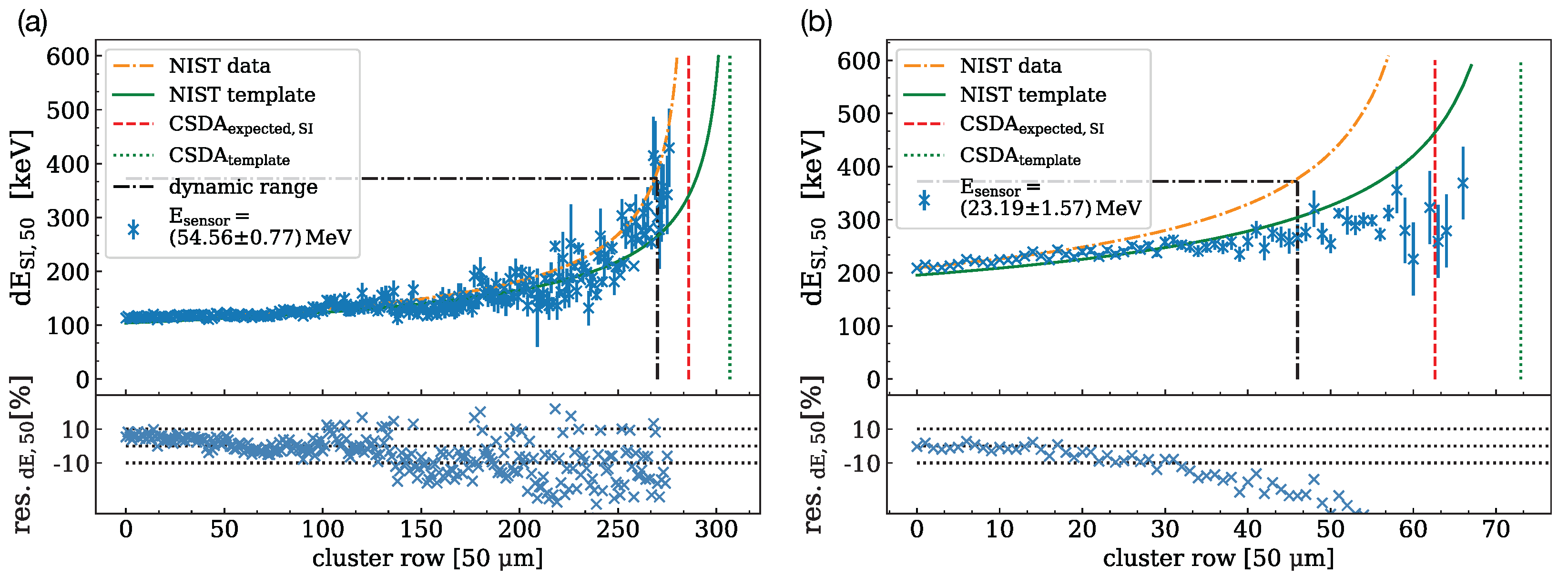
Figure 11 shows the deposited energy per pixel d E SI , 50 for all pixels in a track, averaged over all tracks recorded in a measurement. As the number of protons decreases towards the end of the track, the statistical uncertainty increases. To guide the eye, the orange curve shows the expected energy deposition per pixel according to the NIST database for the incident proton energy.
To determine the energy of protons based on the energy deposition along the track, we use the NIST data in a template method. First, the proton energy E sensor , est is estimated using the longest track in the measurement, as described above. For an energy interval of ± 5 MeV around the estimate, the energy deposition curves are extracted from NIST in steps of 0.1 MeV. Then, the template that agrees best with the measured data is determined using the minimum reduced χ 2 .
The green curve in Figure 11 shows the energy deposition curve according to the template method, indicating a systematic overestimation of the range.

3. Results

3.1. Let Spectra Measurement

A linear fit to the data shown in Figure 9 yields a value for the scaling parameter in Equation (2) of a = ( 0.824 ± 0.002 ) 1 keV . Figure 12 shows the good agreement of the deposited energy after scaling d E SI , 200 with the expected energy deposition as a function of the incident proton energy E sensor . The relative deviation from the NIST expectation is plotted in the lower part of the figure, showing an average deviation of 0.82%.
For low-energy protons, the energy deposited in the sensor exceeds the dynamic range of the detector, resulting in d E SI , 200 not being a good estimator anymore. Since, in the worst case, the full energy is deposited in a single pixel, rather than a larger cluster, the data points are excluded from analysis if the expected deposited energy exceeds the measurement range of a single pixel. This defines the lower limit of proton energies that the direct LET measurement is suitable for, indicated by the red dashed line in Figure 12. Following the calibration, the energy of the proton E proton , as well as its measured range in water and the respective uncertainties are then extracted from the NIST database.
To verify the calibration procedure and the applied uncertainties on the mean deposited energy, the calibration is performed excluding one test data point and used to calculate d E SI , 200 , cal . and the corresponding uncertainty for this test data point (leave-one-out cross-validation). This is repeated for every data point, allowing to histogram the pull of this unbiased calibration:
pull = d E SI , 200 , cal . d E expected , SI , 200 σ dE , sensor , cal . .
The result is shown in Figure 13. The width of the distribution was found to be σ pull = 0.88 , which indicates a slight overestimation of the systematic uncertainties due to the conservative evaluation.
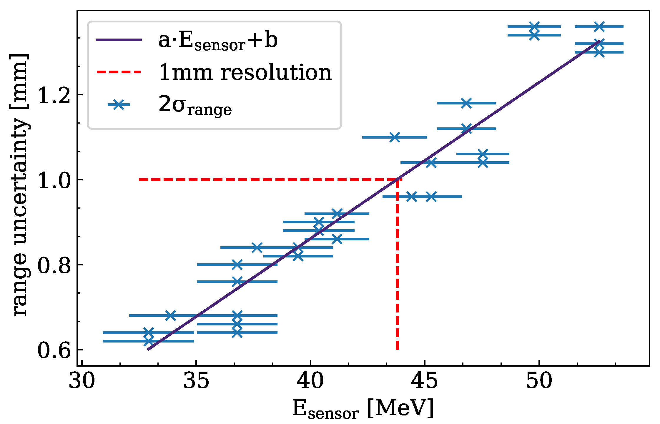
In order to estimate the range resolution, we repeat the process of determining the unbiased calibration for each data point and calculate the range for the respective point. We define the difference of the range values to be statistically significant, if it is larger than twice their uncertainty σ range , depicted in Figure 14.
For daily QA, a deviation of the proton range of 1 mm needs to be measurable. Using a linear fit, an upper energy limit to fulfill the QA requirement of E max . = ( 43.8 ± 3.2 ) MeV can be determined for the selected tuning.

3.2. Track LET Measurement

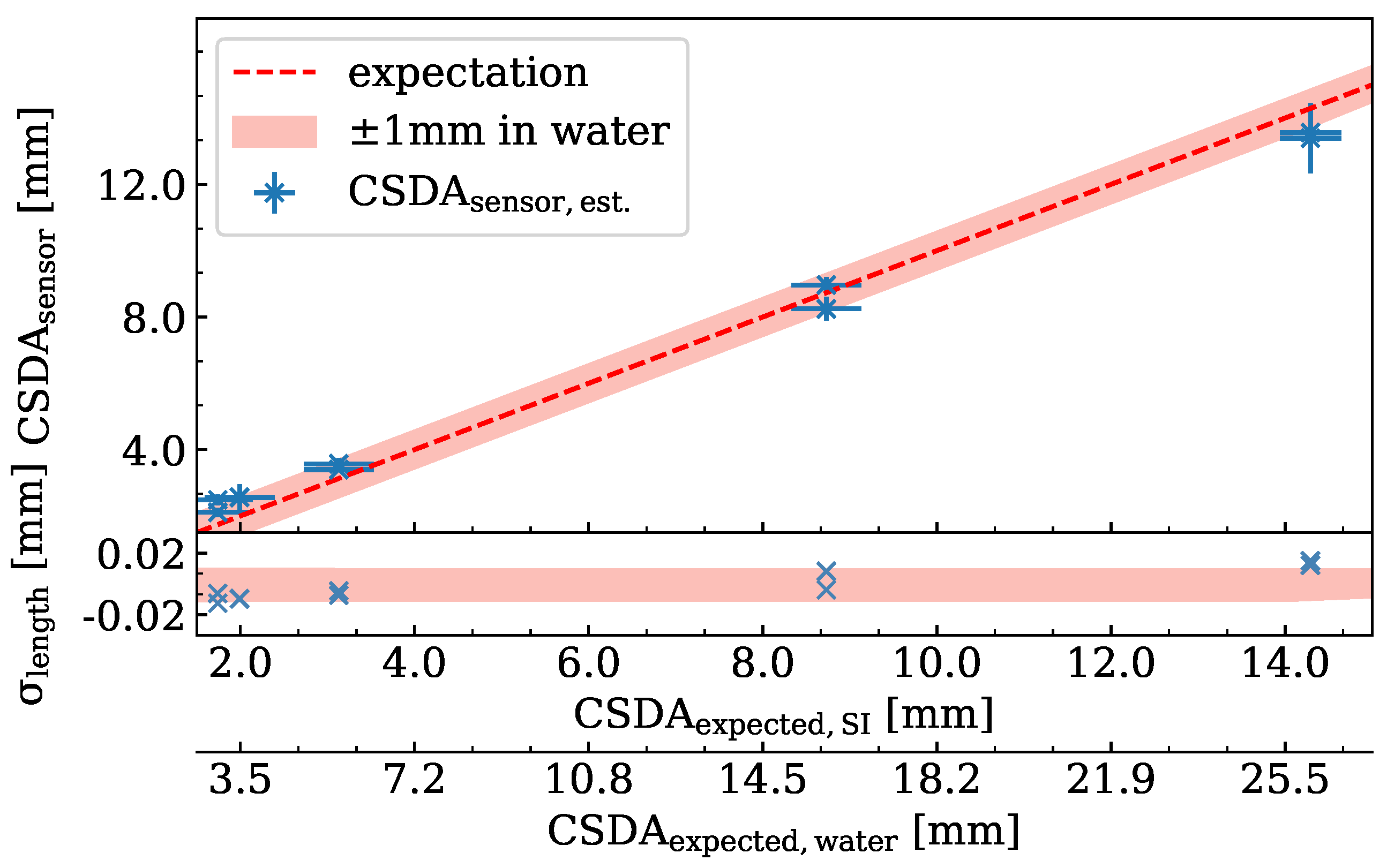
The average maximum track length C S D A sensor , est for the two measurements performed per energy are shown in Figure 15 as a function of the expected track length in silicon, C S D A expected , SI . A second x-axis shows the CSDA range in water C S D A expected , water , and the light red band indicates a ± 1   m m margin of the range in water.
As described above, protons with the highest energy are the most likely to undergo scattering out of the sensor due to their long tracks. This results in low statistics for the longest track lengths, as well as a systematic underestimation of the track length. For a low proton energy, C S D A sensor , est shows a slight overestimation of the proton range due to range straggling. The range of the protons in water is estimated with a mean absolute deviation σ length = 0.97 mm for ranges in silicon up to 14.29 mm.
The uncertainty of the estimated CSDA range is dominated by the statistical uncertainty of the energy deposition, which is determined by the probability to measure long clusters. To estimate the range uncertainty, subsamples of 70% of all tracks were selected randomly and the proton range measured using the template method. Repeating this 100 times, the lowest and highest measured ranges are used to define an uncertainty interval for each measured proton range.
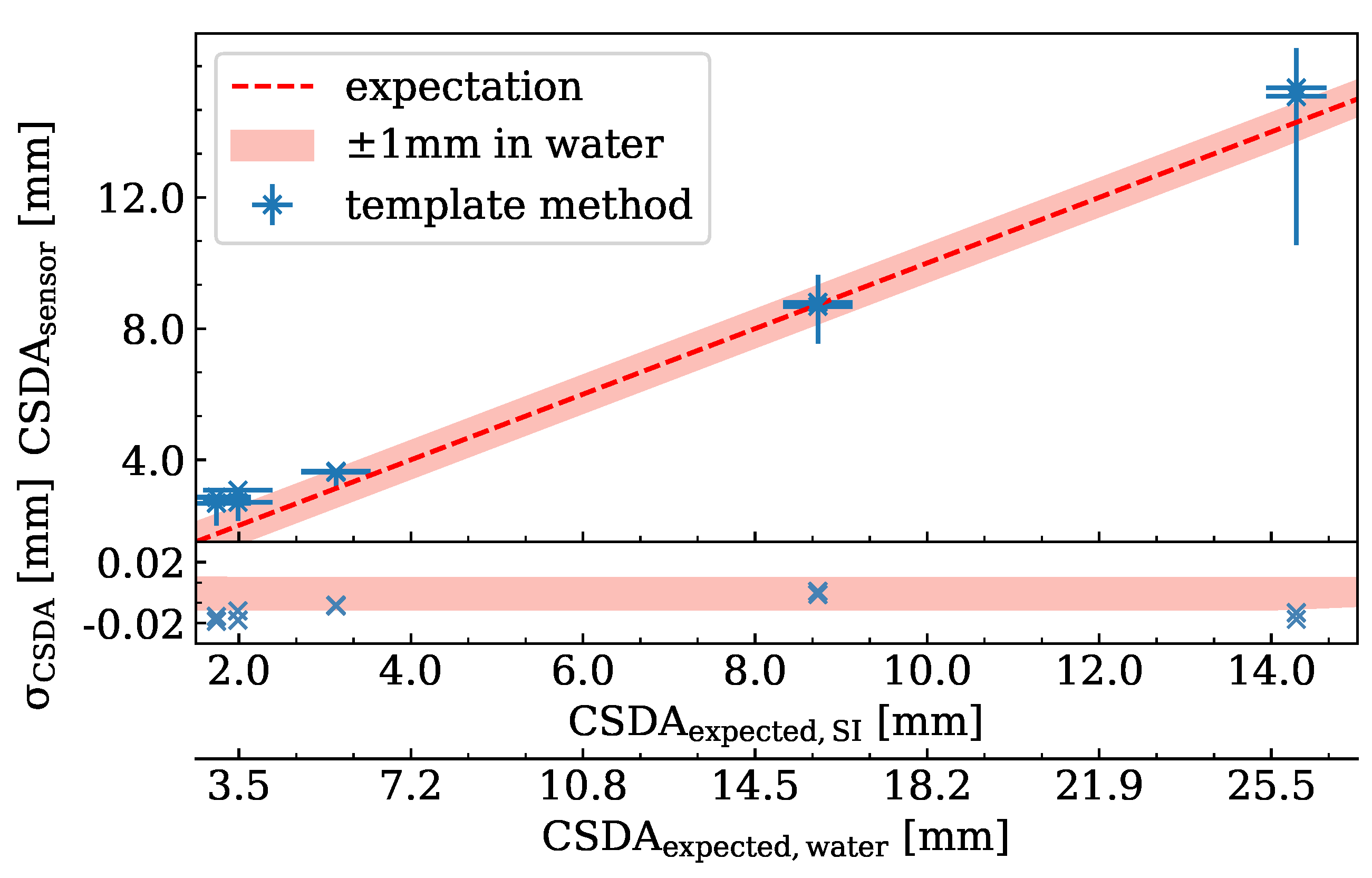
The measured C S D A sensor with the associated uncertainty intervals are compared to the expected C S D A expected in Figure 16. For the longest expected range, the mean uncertainty interval is 5.81 mm in silicon. The template method overestimated the CSDA range slightly for this proton energy due to an underestimation of the deposited energy in the sensor that we discussed already during the previous sections. With decreasing C S D A expected , and thus decreasing probability for the protons to be scattered out of the sensor, the uncertainty interval becomes smaller. For example, for an expected range in silicon of C S D A expected = 8.80 mm, the mean uncertainty of the measured range is ± 0.99 mm.
Measurements of lower C S D A expected are more affected by the limited dynamic energy range of the detector as the fraction of hits exceeding the dynamic range of the respective pixel increases, as is visible in Figure 11b.
The mean uncertainty of the range of the protons in water in the accessible energy range was estimated to be σ CSDA = 1.24 mm. Thus, contrary to the expectation, using the LET along a proton track does not improve the range uncertainty.

4. Discussion

The results on the resolution of the energy and range measurements presented in this publication depend strongly on the dynamic energy range of the detector, which in turn is determined by the tuning of the discriminator thresholds and the amplifier gain of the individual pixels. As the deposited energy of a proton close to the end of its range is considerably higher than what this readout chip was designed for, measurements had to be performed close to the maximum charge the chip can process. This introduces a lower limit for the proton energy that can be measured using the LET spectra measurement method, as indicated in Figure 12, and severely limits the energy resolution of the measurement. The accuracy of the energy and range measurements would benefit greatly from a readout chip specifically designed for large energy deposition.
While the energy-dependent calibration described in Section 3.1 addresses several uncertainties inherently, such as the variations of sensor thickness, scattering of protons inside the sensor, etc., it reduces the statistics of the measurement. It is therefore recommended to repeat the calibration measurement regularly. For daily QA measurements, the staircase phantom should, however, not be used to be able to exploit the available statistics fully. The presented analysis was based on a comparison with the stopping power or CSDA range in water or silicon published by NIST. Uncertainties of the database values, such as the different values of the ionization energies used between NIST [27] and the Geant4 simulations [28], do not affect the calibration of the LET spectra measurement method, because we used the same NIST reference for the calibration and the measurement.
In the second part of the paper, the range of a 99.91 MeV proton beam was determined by investigating the mean LET along the tracks of the protons in silicon. Measurements were performed with range shifters from 5.1   cm to 7.4 cm in thickness to evaluate the applicability of this method for different expected track lengths over the whole silicon sensor.
Despite the fact that the CSDA range is defined as the mean track length of a proton, the length of the longest track in the measurements was shown to be a good estimator for the CSDA range of the protons, yielding a range uncertainty of σ length = 0.93 mm. For larger statistics, the maximum track length will cease to be a good estimator, as the probability for longer tracks due to straggling increases, leading to an overestimation of the CSDA range.
Measurements of the mean LET per pixel along the proton tracks have not shown improvements in the range uncertainty. This could be due to a systematic overestimation of the deposited energy per pixel dE SI ,   50 for protons that do not traverse the pixels in a straight line.
The lateral dimension of the detector of 1.68 cm, as well as the increasing probability for protons to be scattered out of the sensor before the end of their range impose an upper limit on the proton energy that can be measured. Using well-known range shifters, this range can be extended to higher energies at the cost of increasing range straggling of the protons in the range shifters, which impacts the resolution of the range measurement.
As the uncertainty is dominated by the probability of actually measuring the longest cluster, it can be improved by increasing the number of tracks, i.e., the duration of the measurement.
Typical measurements using the IBA MLIC devices (Zebra or Giraffe) use Bortfeld fits to reach an accuracy of up to ± 0.4 mm [8,29]. Another detector system designed for proton therapy QA is the dose magnifying glass, which is also based on a pixelated semiconductor detector. It can distinguish range deviations of ± 0.2 mm for the same energy range used in this study [30,31].
The usage of a radiation hardness hybrid pixelated semiconductor detector like the ATLAS IBL pixel detector is advantageous for daily QA because a simultaneous examination of the spot shape, position, and beam energy is difficult to achieve with common devices. While a Sphinx wedge phantom combined with the Lynx CCD camera (IBA Dosimetry) [32,33] or the Daily-QA3 detector (Sun Nuclear) is sufficient for commonly used spot sizes, the large spatial resolution will allow performing QA measurements for even smaller spots and higher dose gradients in the future [34].

5. Conclusions

In conclusion, track measurements show promising results for the determination of the initial beam energy/range by tracking single protons. Compared to the direct LET spectra measurement, no calibration is required, and protons at clinically relevant energies can be measured through the use of suitable WET plates to shift the total energy deposition of the protons in the sensor. Nevertheless, the direct LET spectra method enables the measurement of the field shape, position, and range at the same time as the measurement of the proton energy. Using the presented tuning, range differences of 1 mm, as required for daily QA, can be distinguished for protons hitting the sensor with energies between 30   MeV and 44 MeV. Using range shifters upstream of the detector thus allows range measurements in the clinically relevant energy range.
This study identified additional requirements for a semiconductor detector for clinical use, such as an improvement of the energy resolution and investigations on the radiation hardness. In addition to the potential applicability during daily QA, the provision of per-proton and per-pixel LET information can improve proton radiography images, which will be considered in subsequent studies.

Author Contributions

Conceptualization, I.S. and J.W.; methodology, I.S. and J.W.; software, I.S.; investigation, I.S., C.M.B., C.B. (Christian Bäumer), C.B. (Carina Behrends), K.K., J.H., M.H., and J.W.; validation, I.S., C.M.B., C.B. (Christian Bäumer), C.B. (Carina Behrends), K.K., and J.W.; formal analysis: I.S.; resources, C.B. (Christian Bäumer), K.K., and B.T.; data curation, I.S.; writing—original draft preparation, I.S. and J.W.; writing—review and editing, C.M.B., C.B. (Christian Bäumer), C.B. (Carina Behrends), K.K., and J.W.; visualization: I.S.; supervision, C.B. (Christian Bäumer), K.K., and J.W.; project administration, K.K. and J.W.; funding acquisition, C.B. (Christian Bäumer), K.K. and B.T. All authors have read and agreed to the published version of the manuscript.

Funding

The presented study was supported by the MERCUR-Stiftung graduate school “Präzisions-protonentherapie—Praxisbezogene Physik und Chemie an der Schnittstelle zur Medizin” (Grant Number St-2019-0007).

Data Availability Statement

Not applicable.

Acknowledgments

The authors would like to thank the IBA PT and the WPE physics team for their support with the irradiations.

Conflicts of Interest

The authors declare no conflict of interest.

Abbreviations

The following abbreviations are used in this manuscript:
LETLinear Energy Transfer
QAQuality Assurance
HEPHigh-Energy Physics
IBLInsertable B-Layer
ToTTime over Threshold
ROIRegion Of Interest
WERWater-Equivalent Ratio
CSDAContinuous Slowing Down Approximation
WETWater-Equivalent Thickness
NISTNational Institute of Standards and Technology

References

  1. Arjomandy, B.; Taylor, P.; Ainsley, C.; Safai, S.; Sahoo, N.; Pankuch, M.; Farr, J.B.; Yong Park, S.; Klein, E.; Flanz, J.; et al. AAPM task group 224: Comprehensive proton therapy machine quality assurance. Med. Phys. 2019, 46, e678–e705. [Google Scholar] [CrossRef] [Green Version]
  2. Granja, C.; Oancea, C.; Jakubek, J.; Marek, L.; Benton, E.; Kodaira, S.; Miller, J.; Rucinski, A.; Gajewski, J.; Stasica, P.; et al. Wide-range tracking and LET-spectra of energetic light and heavy charged particles. Nucl. Instrum. Methods 2021, 988, 164901. [Google Scholar] [CrossRef]
  3. Gehrke, T.; Burigo, L.; Aricó, G.; Berke, S.; Jakubek, J.; Turecek, D.; Tessonnier, T.; Mairani, A.; Martišíková, M. Energy deposition measurements of single 1H, 4He and 12C ions of therapeutic energies in a silicon pixel detector. JINST 2017, 12, P0402. [Google Scholar] [CrossRef]
  4. Rosenfeld, A.; Alnaghy, S.; Petasecca, M.; Cutajar, D.; Lerch, M.; Pospisil, S.; Giacometti, V.; Schulte, R.; Rosso, V.; Würl, M.; et al. Medipix detectors in radiation therapy for advanced quality-assurance. Radiat. Meas. 2020, 130, 106211. [Google Scholar] [CrossRef]
  5. Vignati, A.; Giordanengo, S.; Milian, F.M.; Ganjeh, Z.A.; Donetti, M.; Fausti, F.; Ferrero, M.; Ali, O.H.; Villarreal, O.M.; Mazza, G.; et al. A new detector for the beam energy measurement in proton therapy: A feasibility study. Phys. Med. Biol. 2020, 65, 215030. [Google Scholar] [CrossRef] [PubMed]
  6. Grinstein, S. ATLAS Collaboration. Overview of the ATLAS insertable B-layer (IBL) project. Nucl. Instr. Meth. A 2013, 699, 61–66. [Google Scholar] [CrossRef] [Green Version]
  7. Schilling, I.; Bäcker, C.M.; Bäumer, C.; Behrends, C.; Kröninger, K.; Timmermann, B.; Weingarten, J. Characterization of pixelated silicon detectors for daily quality assurance measurements in proton therapy. arXiv 2022, arXiv:2204.02060. [Google Scholar]
  8. Bäumer, C.; Koska, B.; Lambert, J.; Timmermann, B.; Mertens, T.; Talla, P.T. Evaluation of detectors for acquisition of pristine depth-dose curves in pencil beam scanning. J. Appl. Clin. Med. Phys. 2015, 16, 151–163. [Google Scholar] [CrossRef] [PubMed]
  9. Granja, C.; Jakubek, J.; Martisikova, M.; Kodaira, S.; Polansky, S.; Krist, P.; Zach, V.; Matlocha, T. Dynamic range and resolving power of the Timepix detector to heavy charged particles. JINST 2018, 13, C11003. [Google Scholar] [CrossRef]
  10. Bergmann, B.; Pichotka, M.; Pospisil, S.; Vycpalek, J.; Burian, P.; Broulim, P.; Jakubek, J. 3D track reconstruction capability of a silicon hybrid active pixel detector. Eur. Phys. J. C 2017, 77, 1–9. [Google Scholar] [CrossRef] [Green Version]
  11. Giordanengo, S.; Palmans, H. Dose detectors, sensors, and their applications. Med. Phys. 2018, 45, e1051–e1072. [Google Scholar] [CrossRef] [PubMed]
  12. Garcia-Sciveres, M.; Arutinov, D.; Barbero, M.; Beccherle, R.; Dube, S.; Elledge, D.; Fleury, J.; Fougeron, D.; Gensolen, F.; Gnani, D.; et al. The FE-I4 Pixel Readout Integrated Circuit. Nucl. Instr. Meth. A 2011, 636, 155–159. [Google Scholar] [CrossRef] [Green Version]
  13. Weingarten, J. ATLAS IBL sensor qualification. JINST A 2012, 7, C01039. [Google Scholar] [CrossRef] [Green Version]
  14. Klein, C.A. Bandgap Dependence and Related Features of Radiation Ionization Energies in Semiconductors. J. Appl. Phys. 1968, 39, 2029–2038. [Google Scholar] [CrossRef]
  15. Mohammadian-Behbahani, M.R.; Monaco, V.; Abujami, M.; Bersani, D.; Data, E.M.; Galeone, C.; Giordanengo, S.; Ali, O.H.; Villarreal, O.A.; Milian, F.M.; et al. Two-channel combination methods for count-loss correction in radiation measurements at high rates and with pulsed sources. Nucl. Instrum. Methods Phys. Res. A Accel. Spectrom. Detect. Assoc. Equip. 2022, 1040, 167195. [Google Scholar] [CrossRef]
  16. Petzoldt, J.; Roemer, K.E.; Enghardt, W.; Fiedler, F.; Golnik, C.; Hueso-Gonzalez, F.; Helmbrecht, S.; Kormoll, T.; Rohling, H.; Smeets, J.; et al. Characterization of the microbunch time structure of proton pencil beams at a clinical treatment facility. Phys. Med. Biol. 2016, 61, 2432. [Google Scholar] [CrossRef] [Green Version]
  17. Bäumer, C.; Bäcker, C.M.; Gerhardt, M.; Grusell, E.; Koska, B.; Kröninger, K.; Nitsch, C.; Rullkötter, H.; Siregar, H.M.; Timmermann, B.; et al. Measurement of absolute activation cross sections from carbon and aluminum for proton therapy. Nucl. Instrum. Methods Phys. Res. B 2019, 440, 75–81. [Google Scholar] [CrossRef]
  18. Behrends, C.; Bäcker, C.M.; Schilling, I.; Zwiehoff, S.; Weingarten, J.; Kröninger, K.; Rehbock, C.; Barcikowski, S.; Wulff, J.; Bäumer, C.; et al. The radiosensitizing effect of platinum nanoparticles in proton irradiations is not caused by an enhanced proton energy deposition at the macroscopic scale. Phys. Med. Biol. 2022, 67, 155023. [Google Scholar] [CrossRef]
  19. Campbell, M.; Havranek, V.; Heijne, E.; Holy, T.; Idarraga, J.; Jakubek, J.; Lebel, C.; Leroy, C.; Llopart, X.; Novotny, J.; et al. Charge collection from proton and alpha particle tracks in silicon pixel detector devices. IEEE Nucl. Sci. Symp. Conf. Rec. 2007, 2, 1047–1050. [Google Scholar]
  20. Olsansky, V.; Granja, C.; Oancea, C.; Mackova, A.; Havranek, V.; Chvatil, D.; Bila, J. Spectral-sensitive proton radiography of thin samples with the pixel detector Timepix3. JINST 2022, 17, C04016. [Google Scholar] [CrossRef]
  21. Kroupa, M.; Bahadori, A.; Campbell-Ricketts, T.; Empl, A.; Hoang, S.M.; Idarraga-Munoz, J.; Rios, R.; Semones, E.; Stoffle, N.; Tlustos, L.; et al. A semiconductor radiation imaging pixel detector for space radiation dosimetry. Life Sci. Space Res. 2015, 6, 69–78. [Google Scholar] [CrossRef] [PubMed]
  22. International Commission on Radiation Units and Measurements. Linear Energy Transfer; ICRU Report: Bethesda, MD, USA, 1970; Volume 16. [Google Scholar]
  23. Berger, M.; Coursey, J.S.; Zucker, M.A.; Chang, J. ESTAR, PSTAR, and ASTAR: Computer Programs for Calculating Stopping-Power and Range Tables for Electrons, Protons, and Helium Ions (Version 1.2.3). [Online]. 2005. Available online: http://physics.nist.gov/Star (accessed on 15 June 2022).
  24. Parisi, A.; Olko, P.; Swakoń, J.; Horwacik, T.; Jabłoński, H.; Malinowski, L.; Nowak, T.; Struelens, L.; Vanhavere, F. Microdosimetric characterization of a clinical proton therapy beam: Comparison between simulated lineal energy distributions in spherical water targets and experimental measurements with a silicon detector. Phys. Med. Biol. 2022, 67, 015006. [Google Scholar] [CrossRef]
  25. Behrends, C.; Bäumer, C.; Verbeek, N.; Ehlert, J.; Prasad, R.; Wulff, J.; Lühr, A.; Timmermann, B. Providing proton fields down to the few-MeV level at clinical pencil beam scanning facilities for radiobiological experiments. Phys. Med. Phys. 2022, 49, 666–674. [Google Scholar] [CrossRef]
  26. Paganetti, H. Proton Therapy Physics; CRC Press: Boca Raton, FL, USA, 2018. [Google Scholar]
  27. International Commission on Radiation Units and Measurements. Stopping Powers and Ranges for Protons and Alpha Particles; ICRU Report: Bethesda, MD, USA, 1993; Volume 49. [Google Scholar]
  28. Sigmund, P.; Schinner, A.; Paul, H. Errata and addenda for ICRU report 73, stopping of ions heavier than helium. J. ICRU 2009, 5, 1–10. [Google Scholar]
  29. Dhanesar, S.; Sahoo, N.; Kerr, M.; Taylor, M.B.; Summers, P.; Zhu, X.R.; Poenisch, F.; Gillin, M. Quality assurance of proton beams using a multilayer ionization chamber system. Med. Phys. 2013, 40, 092102. [Google Scholar] [CrossRef] [PubMed]
  30. Catalano, R.; Petringa, G.; Cuttone, G.; Bonanno, V.P.; Chiappara, D.; Musumeci, M.S.; Puglia, S.M.; Stella, G.; Scifoni, E.; Tommasino, F.; et al. Transversal dose profile reconstruction for clinical proton beams: A detectors inter-comparison. Phys. Med. 2020, 70, 133–138. [Google Scholar] [CrossRef]
  31. Debrot, E.; Mundy, D.; Guatelli, S.; Petasecca, M.; Perevertaylo, V.; Beltran, C.; Rosenfeld, A.B. The dose magnifying glass quality assurance system for daily proton therapy range verification. Phys. Med. Biol. 2021, 66, 094001. [Google Scholar] [CrossRef]
  32. Placidi, L.; Togno, M.; Weber, D.C.; Lomax, A.J.; Hrbacek, J. Range resolution and reproducibility of a dedicated phantom for proton PBS daily quality assurance. Z. Med. Phys. 2018, 28, 310–317. [Google Scholar] [CrossRef] [PubMed]
  33. Rana, S.; Bennouna, J.; Samuel, E.J.; Gutierrez, A.N. Development and long-term stability of a comprehensive daily QA program for a modern pencil beam scanning (PBS) proton therapy delivery system. J. Appl. Clin. Med. Phys. 2019, 20, 29–44. [Google Scholar] [CrossRef] [PubMed] [Green Version]
  34. Bäumer, C.; Fuentes, C.; Janson, M.; Matic, A.; Timmermann, B.; Wulff, J. Stereotactical fields applied in proton spot scanning mode with range shifter and collimating aperture. Phys. Med. Biol. 2019, 65, 155003. [Google Scholar] [CrossRef]
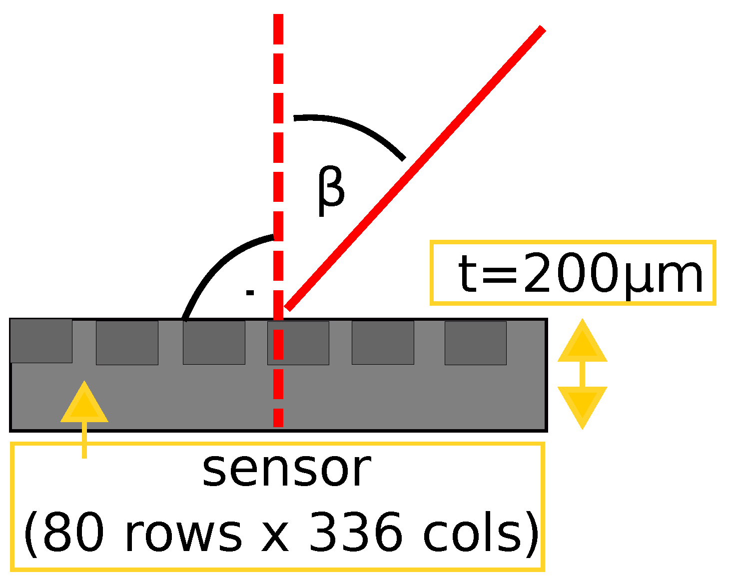
Figure 1. Sketch to define the incident angle β with respect to the normal of the detector surface. The thickness t of the sensor and the pixelation are indicated.
Instruments 06 00080 g001
Figure 2. Sketch to illustrate the different stages of the proton energy: the proton energy delivered by the accelerator E init ; the proton energy behind the variable thickness of RW3 slabs E phantom ; the proton energy incident on the silicon sensor E sensor .
Instruments 06 00080 g002
Figure 3. Picture of a staircase phantom placed upstream of the pixel detector for the LET spectra measurement campaign.
Instruments 06 00080 g003
Figure 4. Map of mean deposited energy for every pixel measured with a beam energy of E phantom 65.4 MeV. The colored frames indicate two example regions of interest, highlighting the variation of the deposited energy across the regions of the staircase phantom.
Instruments 06 00080 g004
Figure 5. Sketch illustrating the direction of the proton pathway through the sensor aligned parallel with the beam axis.
Instruments 06 00080 g005
Figure 6. Experimental setup showing the detector mounted on the goniometer and aligned parallel with the beam axis.
Instruments 06 00080 g006
Figure 7. Deposited energy spectra for (a) phantom thickness of 2.0 cm, corresponding to E sensor 36.8 MeV and for (b) phantom thickness of 1.2 cm, corresponding to E sensor 49.8 MeV . The frames identify the ROIs according to Figure 4.
Instruments 06 00080 g007
Figure 8. Calculation of the expected deposited energy in the sensor using the NIST database, the WET of the RW3 plates, and the WET of the corresponding ROI for the staircase phantom.
Instruments 06 00080 g008
Figure 9. Measured mean deposited energy in silicon d E SI , 200 versus the expected deposited energy d E expected , SI . Results are plotted before (purple squares) and after calibration (green stars).
Instruments 06 00080 g009
Figure 10. Track length distributions along the beam axis for all tracks measured for two different energies: (a) E sensor = ( 54.56 ± 0.77 ) MeV and for (b) E sensor = ( 23.19 ± 1.57 ) MeV. The dotted red line indicates the expected CSDA range of the protons in the silicon sensor.
Instruments 06 00080 g010
Figure 11. Mean deposited energy d E SI , 50 per pixel along the proton tracks for (a) E sensor = ( 54.56 ± 0.77 ) MeV and (b) E sensor = ( 23.19 ± 1.57 ) MeV . The red line indicates the expected energy deposition according to the NIST database and the green line the energy deposition curve calculated by using the template method. The dynamic energy range of the detector, the expected CSDA range, and the measured CSDA range are highlighted as dotted lines. The relative difference between the expected energy deposition (orange curve) and the measured d E SI , 50 is shown in the plots below.
Instruments 06 00080 g011
Figure 12. Calibrated results of the mean deposited energy d E SI , 200 , cal and their relative deviation from the NIST expectation. The minimum energy E sensor , min = 30.4 MeV measurable with this configuration of the detector and the resulting data, which had to be excluded from the analysis, are highlighted.
Instruments 06 00080 g012
Figure 13. Histogrammed pull for calibrated energy deposition in silicon. The mean of the distribution and the corresponding standard deviation are highlighted in red.
Instruments 06 00080 g013
Figure 14. Uncertainty of the measured proton range in water as a function of the expected incident proton energy E sensor ( a = ( 0.037 ± 0.002 ) mm MeV , b = ( 0.60 ± 0.08 ) mm ). The upper energy limit E max . = ( 43.8 ± 3.2 ) MeV to fulfill the QA requirement is highlighted.
Instruments 06 00080 g014
Figure 15. Comparison of C S D A expected , SI for different initial beam energies and the corresponding measured CSDA range C S D A sensor , est estimated by using the longest measured cluster length. The red dotted line indicates the expectation and the light red colored interval the deviation ± 1 mm of C S D A expected , water . The accuracy of the estimator is illustrated using the parameter σ length .
Instruments 06 00080 g015
Figure 16. Comparison of C S D A expected , SI for different initial beam energies and the corresponding measured CSDA range C S D A sensor , est estimated by using the template. The red dotted line indicates the expectation and the light red colored interval the deviation ± 1 mm of C S D A expected , water . The accuracy of the estimator is illustrated using the parameter σ CSDA .
Instruments 06 00080 g016
Publisher’s Note: MDPI stays neutral with regard to jurisdictional claims in published maps and institutional affiliations.