Abstract
This paper presents the requirements and design solutions of the chopper for the injection line of the cyclotron of the SPES project at Laboratori Nazionali di Legnaro. The device aims to precisely modulate the average current injected into the cyclotron, thereby controlling the current it delivers. A precise control of the beam current is essential for many experiments foreseen for the cyclotron. Due to safety constraints and limited space, a tailored design has been developed. The chopper features a Wien filter configuration, where the electric field is pulsed and the magnetic field is generated by permanent magnets.
1. Introduction
One of the main goals of the project “Selective Production of Exotic Species” (SPES) [1,2] is the production of exotic nuclei using the Isotope Separation On-Line (ISOL) method [3,4]. At the center of an ISOL facility, there is the target system equipped with fissionable elements in the core. This last requires precise balancing of the heating load to maintain the operational temperature. The heating power sources are the Ohmic effect and the proton beam. Therefore, the beam current on the target must be carefully increased from 0 A to approximately 200 A [5]. One of the most effective ways to achieve precise control of the target current is to vary the current injected from the ion source into the accelerator, which is a cyclotron in the SPES project [6,7].
To vary the injected current, several options are available: adjusting the settings of the source, inflector, or cyclotron cavities, or introducing an aperture, a de-phased buncher, or a chopper in the injection line. Among these, the preferred solution is the introduction of a chopper, as implemented in other similar facilities, such as Arronax [8].
For this purpose, a chopper can operate at frequencies lower than the cyclotron cavities (approximately 56 MHz), allowing it to modify the average current delivered by the cyclotron by selecting the number of bunches within a given period, while keeping the charge per bunch constant.
The chopper to be introduced in the injection line of the SPES cyclotron must also meet additional requirements, necessitating a tailored design. Specifically, it must ensure fail-safe operations and be very compact due to the limited space available in the injection line. The first requirement can be addressed by using the magnetic field of a permanent magnet, periodically compensated by an electric field, while the second requirement necessitates overlapping the magnetic and electric fields to create a Wien filter [9]. Although this is not a common design, it has been previously explored, as noted in [10,11,12].
This article outlines the requirements for the chopper, describes the solutions developed to meet them, and presents the final design along with the expected performance based on numerical simulations.
2. The Injection Beam Line of the SPES Cyclotron
The cyclotron for the SPES project is capable of accelerating H− ions up to 70 MeV with a maximum particle current of 750 (52 kW of extracted power). Further details can be found in [13].
The injection beam line is located below the cyclotron, in a pit, and its main components consist of an H− source, a beam stopper, two solenoids, two quadrupoles, two steering magnets, and a collimator. A schematic, detailing the distances between these elements, is presented in Figure 1a.
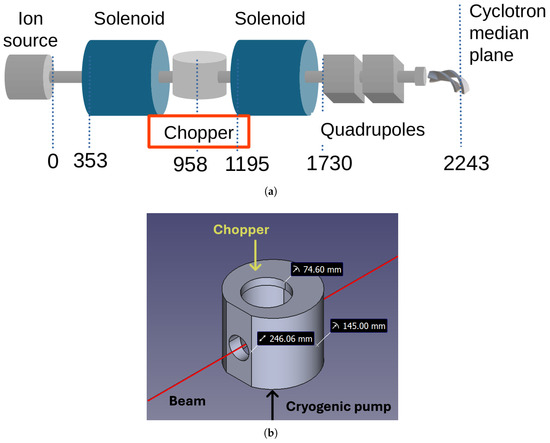
Figure 1.
(a) Schematic representing the elements composing the injection line. (b) The design of the diagnostic chamber located 958 mm from the source output. In the picture, there are also the principal dimensions and the foreseen location of the chopper and cryogenic pump.
As shown in the schematic, there is a small chamber located between the two solenoids, approximately 1.3 m below the cyclotron median plane, designed to host one device at a time. The current plan is to install either a buncher, a chopper, or a pepper pot device, depending on the target requirements. This chamber is roughly cylindrical, measuring about 250 mm in length and 145 mm in radius, with its axis orthogonal to the H− beam direction. It has two access points: one is occupied by a cryogenic pump, while the other is available for inserting the required device. The radius of this latter flange is 75 mm.
A simplified design of the chamber is given in Figure 1b.
3. The Chopper Setup
The ISOL target requirements include ramping the proton beam current up or down from 0 to 200 A with an increment step of 0.5 A or less [14]. Additionally, to prevent unexpected proton beam current increases due to a controller failure, the system should be fail-safe, i.e., normally deflecting.
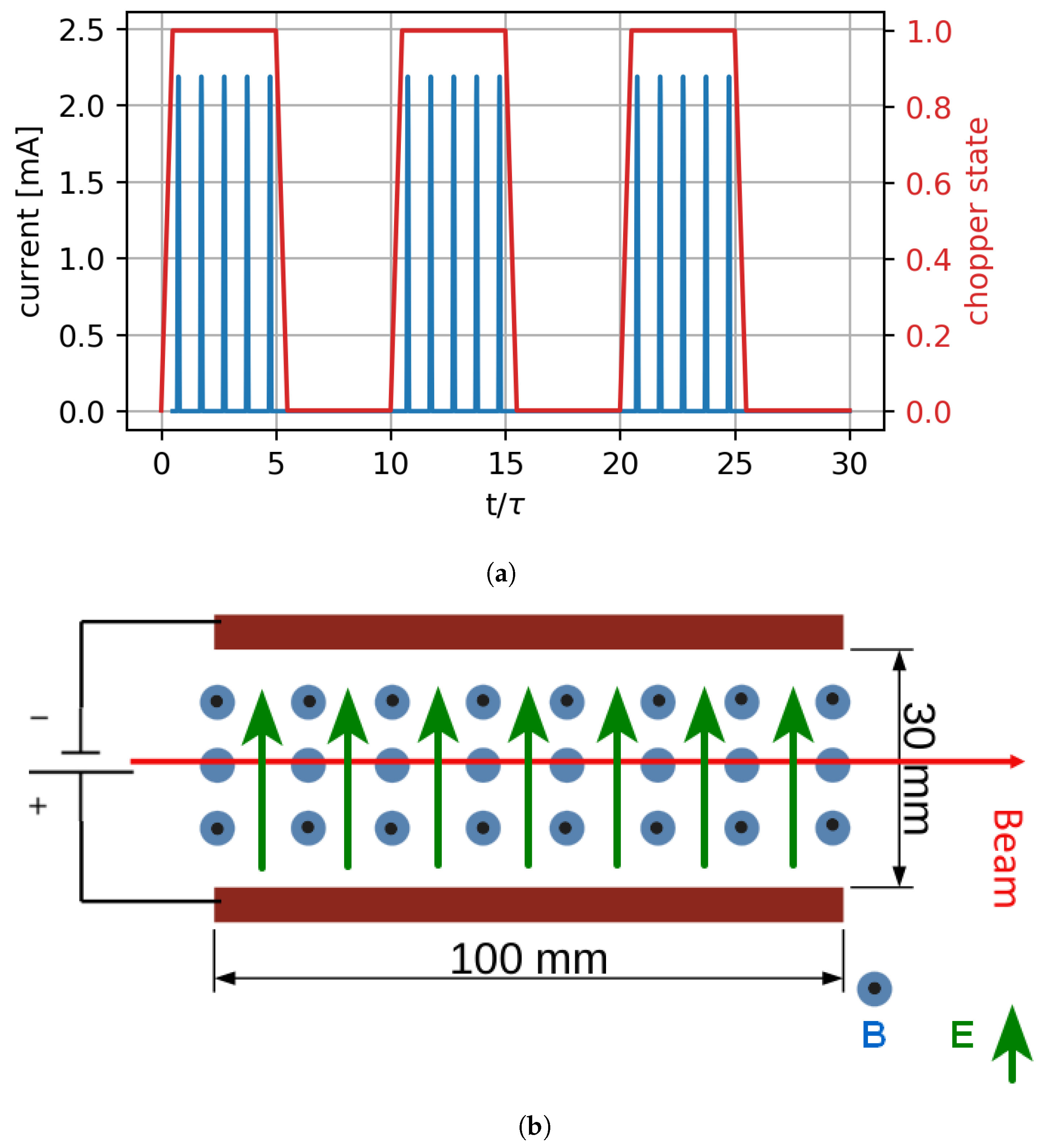
Since short beam trips are not problematic for the ISOL target (numerical analysis indicates that beam trips lasting up to 1 s are sustainable), the average current can be varied by adjusting the number of bunches within a fixed period, rather than altering the charge of each bunch. This approach allows the current controller to operate at a fraction of the cyclotron cavities frequency, creating trains of bunches separated by empty intervals. In this way the complexity of the power supply chain can be reduced [15]. The ratio between the lengths of the bunch trains and the empty intervals determines the average current. The resulting time plot of the bunches is schematically shown in Figure 2a.

Figure 2.
(a) An exemplifying timeline for the bunches sent by the cyclotron to the target (blue curve. Right axis) when the chopper operates with a duty cycle equals to 50% (the red curve represents the chopper state: 1 is on, 0 is off. Left axis). In this example, the chopper has a frequency of one tenth of the cyclotron. (b) The simplified scheme that allows computation of the deflection of the H− beam as a function of the magnetic flux density and then the electric field as a function of the magnetic flux density.
In this context, a single bunch represents the smallest amount of current. Consequently, with this type of controller, the number of bunches within one operational interval dictates the minimum possible increment in current. For instance, a controller frequency of 560 kHz, which is 1/100th of the cyclotron frequency, allows trains with a maximum of 100 bunches, resulting in a resolution of 1%. To achieve a sufficiently high current resolution, the operating frequency should be less than 1/400th of the cyclotron frequency, leading to a maximum theoretical frequency of 140 kHz.
As mentioned earlier, this device must be capable of stopping the H− beam even in the event of a power supply failure. One solution is to provide a constant deflection using a permanent magnet, while an alternating electrostatic field provides the counter-deflection. To ensure a compact design, the electric and magnetic fields should be perpendicular to each other, forming a Wien filter configuration. The dimensions are also crucial, as the device must be easily removable.
An indicative estimation of the magnetic flux density can be derived from the basic scheme shown in Figure 2b, where the electric field is generated by two electrodes 30 mm apart and 100 mm long, while the magnetic field exits the picture and is present only between the two electrodes. The length and distance of the electrodes are initial educated guesses, taking into account space constraints.
As detailed in Section 2, this device must be inserted through a flange with a diameter of 150 mm, which determines the maximum length of the two electrodes (they will be oriented transversely). Conversely, reducing the distance between the electrodes offers several advantages, such as lowering the voltage required to achieve the same electric field or making it more uniform. However, the minimum distance between the electrodes is constrained by the H− beam envelope, estimated to be approximately 10 mm in diameter.
Based on these simplified assumptions, a H− beam deflection between 7 and 14 mm corresponds to a magnetic field ranging from 0.04 T to 0.08 T. Given a 30 mm distance between the electrodes, the electrostatic potential must range from a minimum of 3.5 kV to a maximum of 7 kV.
The mechanical design of the chopper components should ensure that both the magnetic and electric fields be shaped to guarantee the needed homogeneity for maintaining high beam quality. In particular, the magnetic field must be uniform in the order of with respect to the three directions, sharply edged at the borders, and zero outside, with the adequate value to induce the correct deflection to the H− beam. Additionally, the magnetic field must be kept as low as possible to minimize the electrostatic potential required to generate the counter-deflecting electric field.
To meet these requirements, an iron yoke must be introduced. We have preliminarily evaluated several configurations, such as C-shaped or H-shaped yokes, ultimately selecting the configuration shown in Figure 3a. The iron yoke guides and homogenizes the magnetic field in the central gap, with its width determining the field value: enlarging the yoke decreases the magnetic flux density and vice versa.
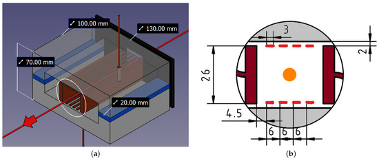
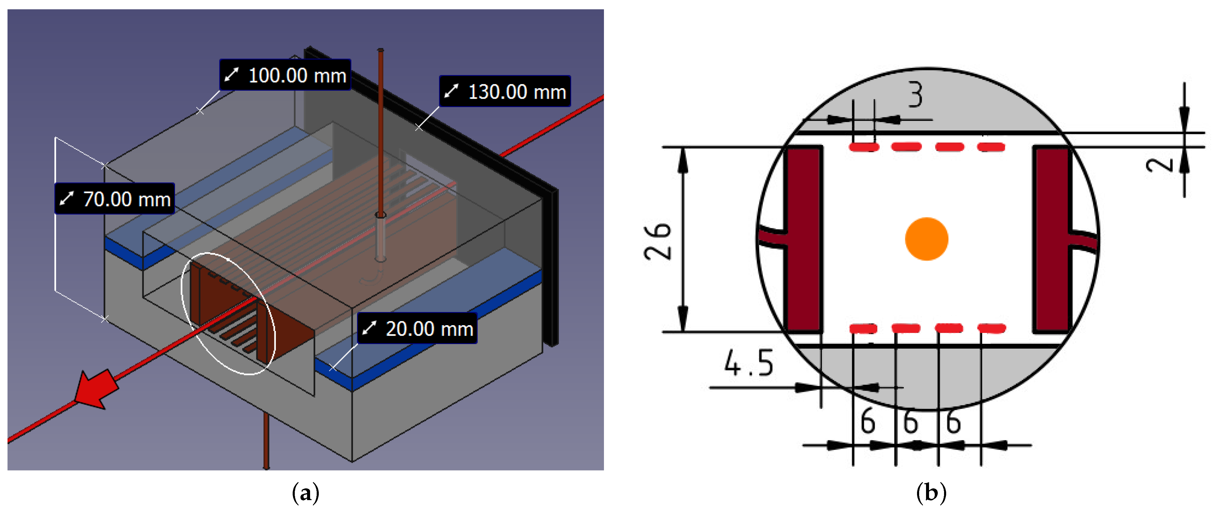
Figure 3.
(a) The final configuration of the chopper system: the permanent magnets are in blue, the iron yoke in gray, the electrodes in brown, and one of the two masks is in black (the other, on the opposite side, is hidden). The red line represents the H− beam trajectory while the white circle is the border of the section depicted in (b). In this second picture, the two main electrodes are in brown, the sub-electrodes in red, the yoke is gray and the orange dot is the H− beam position. All the distances are in mm.
To shape properly the magnetic field along the beam path, ensuring a sharp drop to zero outside the region of interest, two iron masks are added, one before and one after the yoke. An additional benefit of the masks is that they also confine the electric field within the yoke, as their electric potential will be zero. Moreover, the entrance mask protects the chopper components, while the exit mask dumps the H− beams. Moreover, adjusting their distance from the yoke allows for changes in the magnetic flux density within the chopper; moving the masks closer to the yoke decreases the magnetic flux density in the beam path.
In order to ensure a uniform electric field, besides the two main electrodes, eight more sub-electrodes are introduced, four above and four below the H− beam path, in the same way as that explained in [16]. They can be seen in Figure 3b.
4. Electromagnetic Fields Simulation and Beam Dynamics
To determine the optimal dimension of each component, several numerical analyses were conducted. These studies involved an iterative process.
The first analysis aimed to obtain the magnetic flux density generated by the permanent magnets. The second analysis computed the electric field produced by the electrodes. Finally, the third analysis assessed the behavior of a H− beam traveling in the previously obtained fields.
4.1. Magnetic Field
The magnetic field can be determined using Finite Element Analysis (FEA). We employed the ElmerFEM 9.0 software package [17] for this purpose. This method requires a simplified CAD design of the device, along with the selection of materials and properties such as magnetization. In this case, the chosen material for the yoke is iron, conforming to the XC06 standard. The B–H curve for this material is easily available online [18].
As regards magnets, for the specified magnetic flux density, Neodymium magnets have been selected.
The final model to determine the magnetic field is shown in Figure 3a. In the model there are several parameters that allow to tune the magnetic field, one is the yoke width, as stated above, another is the permanent magnet width or thickness.
After some attempt the magnet dimensions were set to 100 mm length, 6 mm thick and 20 mm width while the magnetization is 25EH, that is 1 T of remanent magnetization (equivalent to 800 kA/m).
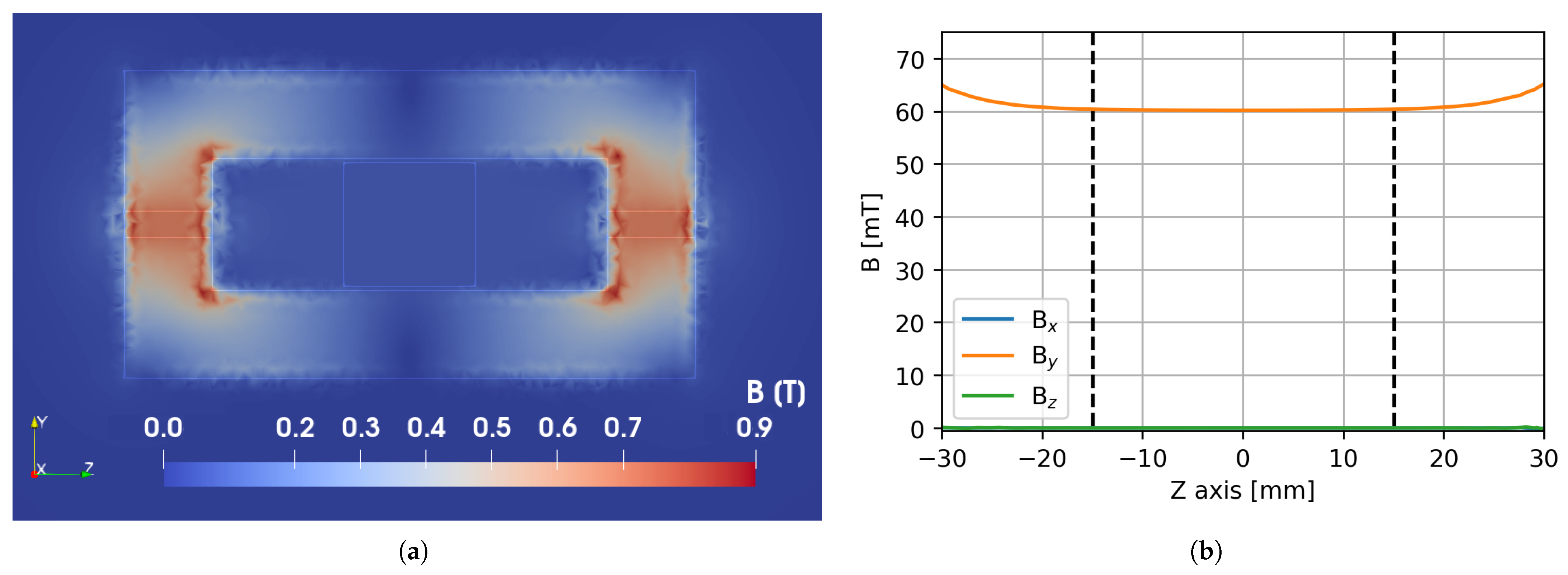
The resulting magnetic flux density in the transverse direction is shown in Figure 4a,b. The plot indicates that the magnetic flux density is vertical (with negligible components in other directions) and fairly uniform within the region of interest, i.e., between the two electrodes, which are positioned 15 mm from the beam axis. The magnetic flux density at the center is 0.06 T.
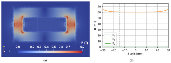
Figure 4.
(a) The magnetic flux density on the transversal plane of the chopper. (b) The magnetic flux density along the horizontal transversal axis in the gap region: the orange line is the one in the vertical direction, green and blue are in the other two directions (the blue line, , is hidden under the green one, ). The two dashed lines indicates the electrodes positions, the beam can pass only between them.
4.2. Electric Field
Similarly to the study of the magnetic field, we computed the electric field using an FEA software package (ElmerFEM 9.0 once again), applying the same 3D model as that described in Figure 3a. In this model, all components are grounded except for the electrodes and sub-electrodes, which are biased symmetrically with respect to the longitudinal vertical plane. This means that if one electrode is at a positive voltage, the corresponding electrode on the opposite side has an equal magnitude of voltage but opposite polarity.
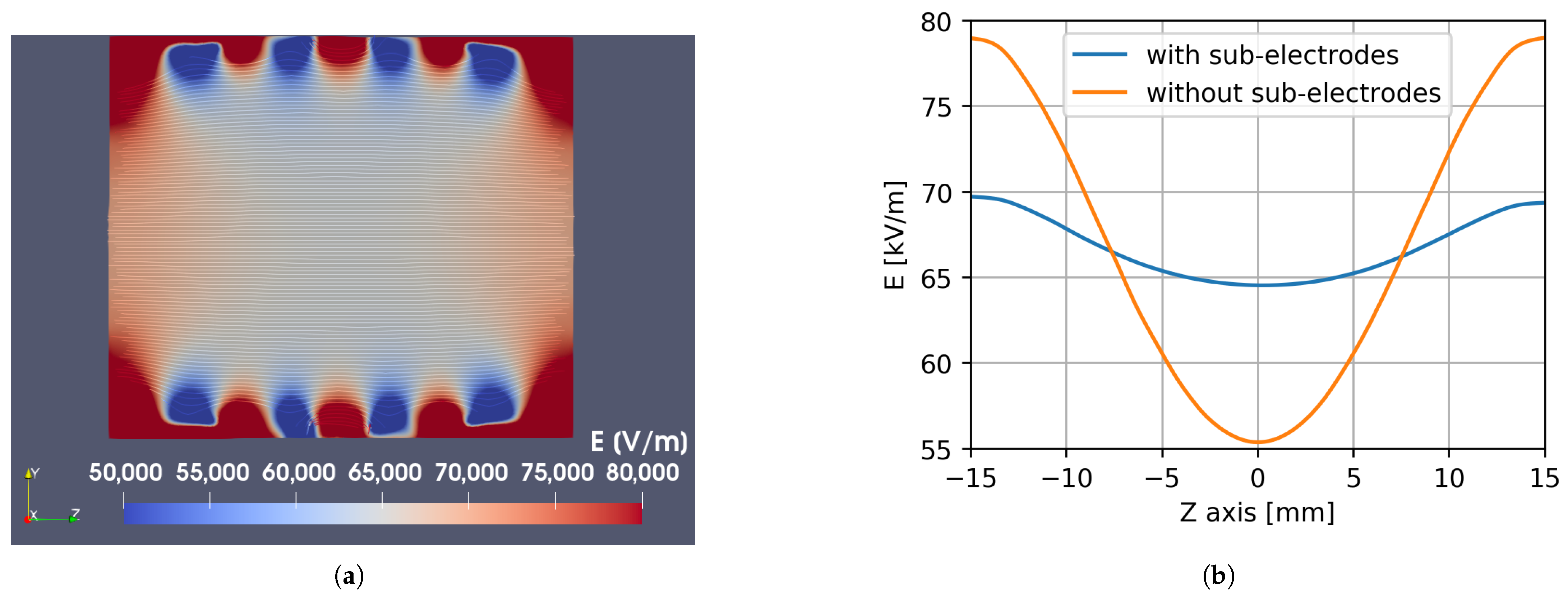
The results are illustrated in Figure 5. The contour plot in (a) represents the electric field magnitude on the transversal plane: the effect of the eight sub-electrodes is clearly visible. In (b) there is a comparison between the Z component of the electric field taken along the axis connecting the center of the two main electrodes: the blue line represents the chopper with the sub-electrodes while the orange line is the case of a chopper without them.

Figure 5.
(a) Contour plot of the electric field magnitude in the transversal plane of the chopper when all the electrodes and sub-electrodes are turned on. (b) The electric field in the Z direction along the Z axis with the sub-electrodes (blue line) and without (orange line).
The simplest method to bias the electrodes and sub-electrodes is to connect them to a voltage divider. Given that the electric field will follow a pulse wave, the resistors in this divider must be appropriately sized to deliver a sufficiently high current, ensuring that the voltage of all sub-electrodes rises as quickly as that of the main electrodes. However, this solution introduces the side effect of the current passing through the divider, which is both a heating problem and a current drain that extends the rising time for the main electrodes.
To address this issue, we have considered the option of disconnecting the sub-electrodes from the main electrodes, maintaining them at their operational potential. In this scenario, since the sub-electrodes are held at a non-zero voltage, they would introduce a static electric field into the beam path. This could potentially perturb the beam dynamics and allows some particles to pass through the chopper even when it is turned off. The impact of this residual electric field on the beam dynamics will be evaluated in Section 4.3.
4.3. Beam Dynamics
To evaluate the effect of the chopper in the injection line and verify if the beam is correctly dumped, the beam line from the source to the cyclotron inflector was simulated using the Simion 8.1 software package [19].
Simion can both compute electric and magnetic fields and also import external ones. In this analysis, the fields related to the chopper and to the inflector, together with the magnetic field of the cyclotron, are computed with a FEA and then imported, while the other fields, which are the magnetic fields of the two solenoids and those of the quadrupoles, are computed in Simion.
A valuable feature of Simion is its ability to run integration of the dynamics alongside a user-programmed file in which one can create specific functions. In our case, this capability has been exploited to define the impact conditions for the beam based on the geometry of the injection line and the chopper.
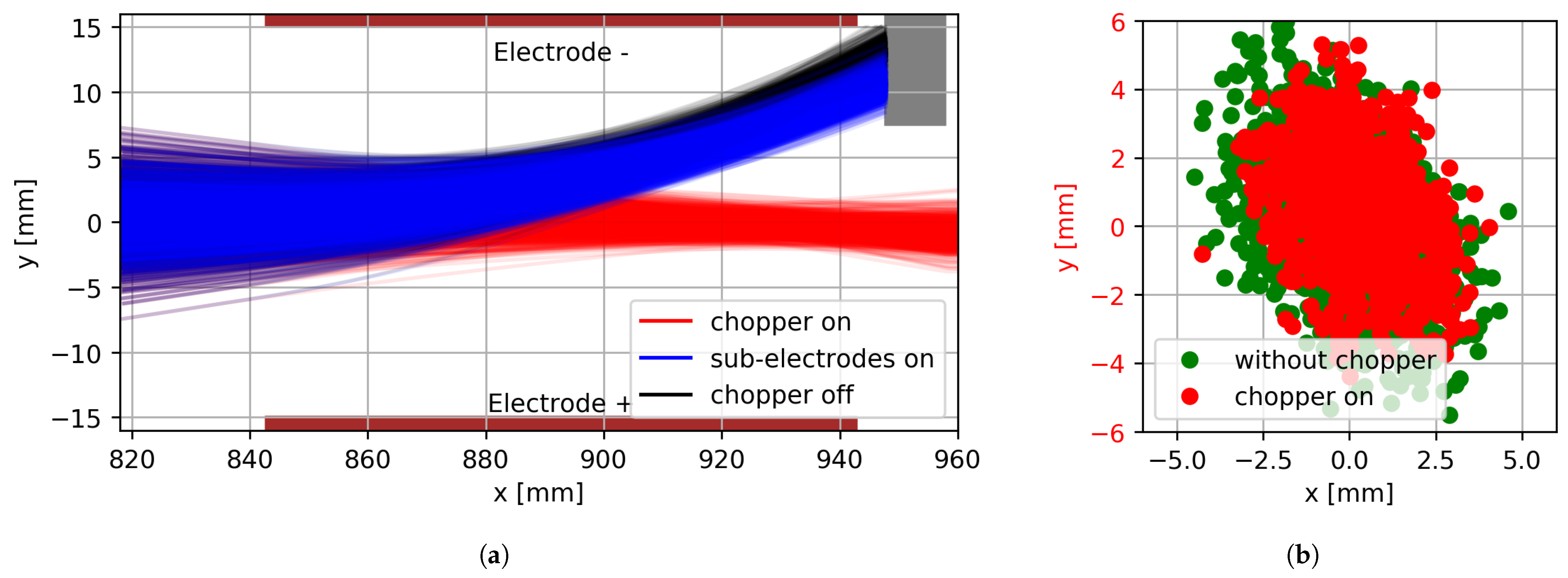
The simulated beam, characterized by measured parameters, consists of 103 particles. The outcomes of the dynamics integration are illustrated in Figure 6. In panel (a), the beam interaction with the dumper (represented as a brown box) is depicted. The beam stops on the dumper when the chopper electrodes are fully deactivated (black lines) and when the sub-electrodes are maintained at their operational voltages (blue lines). These two conditions are related to alternative configurations of the chopper, as explained in Section 5. In both scenarios, the beam is entirely stopped by the dumper.

Figure 6.
(a) The picture shows the H− beam trajectory inside the chopper. The beam color is related to the chopper setting: black is for the electrodes and sub-electrodes off, blue is for the electrodes off and the sub-electrodes on and red is for all the electrodes and sub-electrodes on. The other visible elements are the two electrodes in brown and the dumper in gray. (b) Simulations of the beam recorded at the end of the injection line: the red dots are for the beam passing through the chopper at its ideal voltage, the green dots are for a beam passing the diagnostic chamber without the chopper. This comparison highlights the effects of the chopper at the entrance of the inflector (63 mm from the median plane of the cyclotron).
Panel (b) shows the beams at the inflector entrance with the chopper at its operational voltage (red dots) and without the chopper (green dots). All other elements of the injection line remain unchanged. The chopper exerts a weak focusing effect and the beam remains nearly identical to the unperturbed one.
The simulation results indicate that the beam is correctly stopped in the chopper dumper when there is no electric field. When the sub-electrodes are maintained at their operating voltage and the main electrodes are set to zero, the beam stops slightly displaced but still within the dumper, indicating that the residual electric field has a limited effect.
The optimal working voltage was determined through multiple simulations, gradually increasing the electrode bias. The best transmission after the inflector was identified as the desired spot. Figure 7 presents these simulation results, showing that the optimal working voltage is 2.9 kV, although partial beam transmission begins at around 1.5 kV.
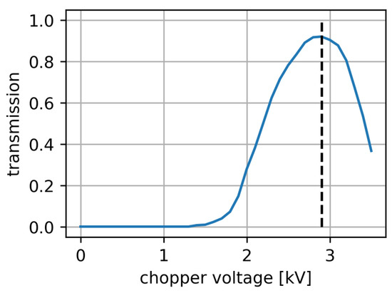
Figure 7.
The transmission of the H− beam after the inflector as a function of the chopper voltage. The best transmission voltage, equal to 2.9 kV, is indicated by the dashed black line.
An important result is that the optimal transmission is 90%, consistent with simulation values obtained without the chopper, suggesting that the chopper perturbations on the beam are negligible for this parameter. Additionally, an analysis of the emittance indicates that the chopper is unlikely to affect the beam quality [20]. The emittances with and without the chopper are compared in Figure 8. The plots show that the beams are very similar, with the primary difference being the focus, represented by the Twiss parameter , which is slightly higher with the chopper, as expected.
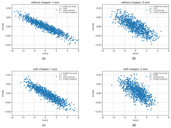
Figure 8.
The emittances at the inflector entrance with the chopper removed (panels (a,b)) and with the chopper activated at its optimal voltage (panels (c,d)).
5. Power Supply Chain
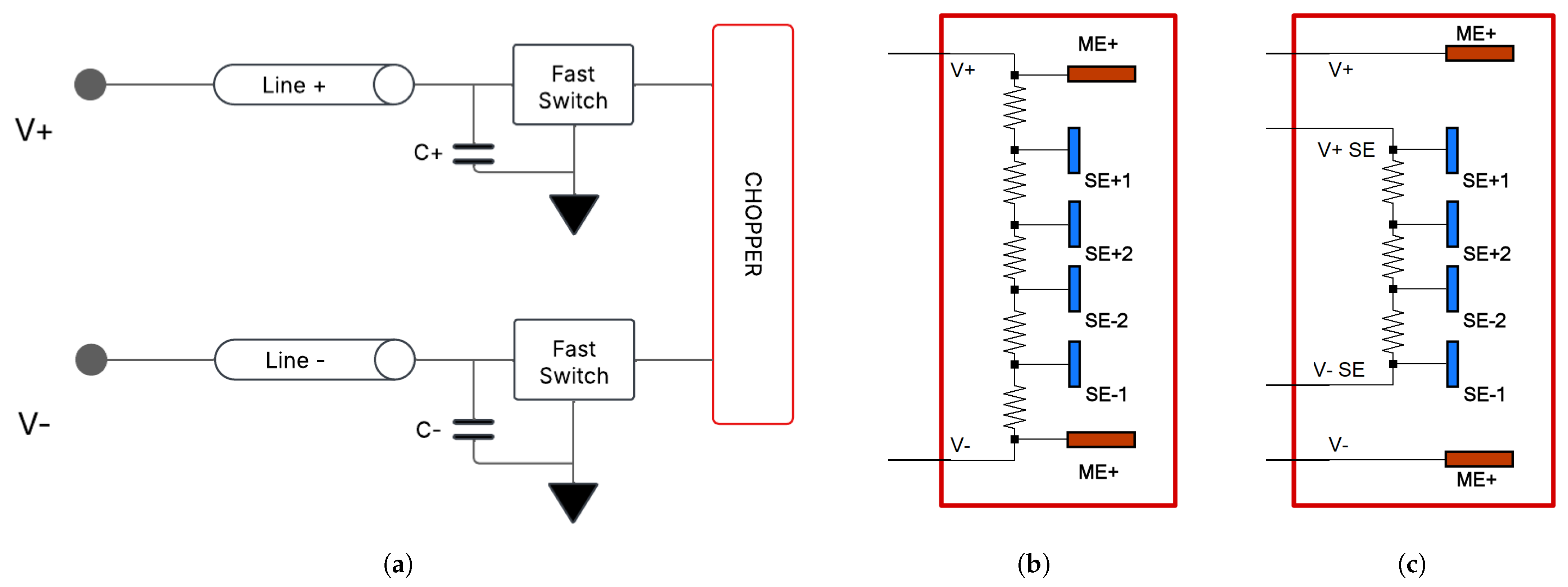
A critical aspect in this kind of devices is the power supply chain. In the present project, the approach is to bias the electrodes with a solid state fast switch in a similar way to that seen in [8].
Simplified electric circuits representing the device are illustrated in Figure 9a,b. They are implemented, with more details, in LTspice 24.1 [21] in order to verify their behavior. In Figure 9a, there are the connections, one for the positive bias and another for the negative bias, from the power supplies to the fast switches [22] (which should be installed as close as possible to the chopper) and from there to the chopper. Just before the fast switches, there is a capacitor to ensure a rapid rise in the voltages of the main electrodes. A capacitance of 100 nF is considered a suitable value.
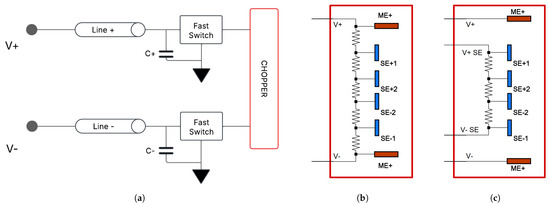
Figure 9.
(a) A simplified electric scheme for the chopper power supply chain. (b) The equivalent circuit of the chopper. (c) The scheme for a chopper with a static voltage divider for the four sub-electrodes.
In Figure 9b, there are the components belonging to the chopper; the two main electrodes are in red while the sub-electrodes are in blue, and all the electrodes are connected by a voltage divider consisting of five resistors.
From electrical point of view, each electrode is a capacitor and its capacitance is estimated using FEA; their values are: 15 pF for the main electrodes, 5 pF for the sub-electrodes, and 1 pF for the mutual capacitance.
The configuration of the chopper elements, with fast switches alternately connecting the electrodes and sub-electrodes to the power supplies and to the ground, ensures that the voltage or, in other terms, the energy accumulated in the electrodes, is discharged every cycle, regardless of the duty cycle. Consequently, the chopper frequency dictates a fixed minimum power consumption. Additionally, there is power absorbed by the voltage divider, which in this case is linearly related to the duty cycle.
In the presented scenario, the energy in the chopper capacitors is given by mJ and the minimum power consumption at a frequency of 5.6 kHz (1/10,000 of the cyclotron frequency) is 0.8 W. Conversely, the power absorbed by the voltage divider depends on its resistance values. The sum of the two must be less than the power available from the power supplies.
The resistances in the voltage divider should be low enough to ensure a rapid increase in the sub-electrodes voltage. However, if the resistance is too low, it will drain most of the current supplied to the chopper, resulting in significant heat generation. For example, five resistors in series, each of 3.5 k, will draw 330 mA and dissipate 1.9 kW of heat when the chopper voltage is set to 5.8 kV. Conversely, five resistors in series, each of 15 k, will draw 77 mA and dissipate 449 W of heat.
The two power supplies, which should be positioned far from the cyclotron to avoid radiation-induced failures, are limited in both voltage and current. In our case, a suitable power supply would have a maximum output of 3 kV and 400 mA corresponding to 1.2 kW.
Using the described circuit, the voltage dynamics for each electrode can be determined, allowing the calculation of the rise times for both the electrodes and sub-electrodes. With a voltage divider resistance of 15 k, the rise time for the sub-electrodes is approximately 136 ns, whereas with 3.5 k, it is 32 ns. The main electrodes achieve their operational voltage very rapidly, in less than 1 ns.
In the presented case, the cyclotron period is 18 ns, while the chopper period can be higher than 180 s (equivalent to 5.6 kHz); therefore, a rise time of 136 ns represents less than 0.1% of the whole cycle, which is below the required resolution, as mentioned in Section 3. Consequently, a voltage divider resistance equal to 15 k is considered a suitable choice.
In Figure 10, three curves represent the voltages for the positive electrodes during a single pulse, with a voltage divider resistance equal to 15 k and a duty period of 250 ns. The plot shows that the main electrode (blue line) reaches its final voltage in a very short interval (less than 1 ns) compared to the two sub-electrodes (orange and green lines).
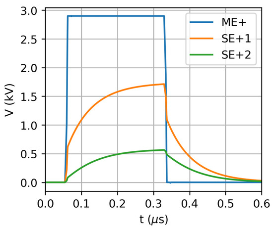
Figure 10.
The charging curves for the positive electrode and sub-electrodes for a short pulse considering the circuit shown in Figure 9b.
As mentioned in Section 4.3, an alternative and more efficient approach is to maintain the sub-electrodes at their operative voltages continuously. This method offers two advantages: only the main electrodes have a variable voltage, resulting in very short rising time, moreover the heating generated by the voltage divider can be significantly reduced, as its resistance can be freely incremented. Another positive impact on total power consumption is that, based on the considerations mentioned above, it no longer depends on the duty cycle but solely on the frequency. The scheme representing this new alternative approach is in Figure 9c.
This configuration has the drawback that a residual electric field being present in the chopper also during the off period, the effect of this electric field was evaluated using Simion in Section 4.3 and was shown to be compatible with the requirements.
6. Conclusions
The present article describes the chopper developed for the injection line of the cyclotron of the SPES project. The chopper varies the injected current in order to finely modulate the average current delivered to the ISOL target. The modulation has to ensure a control of under 0.5 A in a total current up to 200 A.
The chopper features a tailored design to meet safety requirements, ensuring the beam is normally stopped, within a compact space. The solution involves using a Wien filter configuration to minimize bulk, with the magnetic field generated by permanent magnets to ensure reliability.
Additional design details include the homogenization of the electric field using four pairs of sub-electrodes, positioned between the main electrodes and biased with intermediate voltages. Furthermore, the magnetic and electric fields are confined by two ferromagnetic plates situated before and after the chopper.
The design is analyzed exploiting numerical simulations. Using FEA, we have computed the electric and the magnetic fields and using the software package Simion, we have evaluated their effects on the beam dynamics. This analysis demonstrated that the electric and magnetic fields have a very small effect on the beam when the chopper is turned on and, when the chopper is turned off, the beam stops correctly in the dumper.
Finally, to achieve a faster response and mitigate the heating issue, an improved supply configuration was defined. In this configuration, some of the chopper electrodes remain biased even when the chopper is turned off. Simulations indicate that with this setup, the beam consistently stops in the dumper.
The concept design is currently being defined, with the device construction scheduled for mid-year.
Author Contributions
Conceptualization, A.R. and M.M.; methodology, A.R.; software, L.P.; investigation, A.A.; validation, P.A.; data curation, A.R. and A.A.; writing—original draft preparation, A.R. and M.M.; writing—review and editing. All authors have read and agreed to the published version of the manuscript.
Funding
This research received no external funding.
Data Availability Statement
Data will be made available by the corresponding author upon reasonable request.
Conflicts of Interest
The authors declare no conflicts of interest.
Abbreviations
The following abbreviations are used in this manuscript:
| INFN | Istituto Nazionale di Fisica Nucleare |
| ISOL | Isotope Separation On-Line |
| LNL | Laboratori Nazionali di Legnaro |
| SPES | Selective Production of Exotic Species |
| FEA | Finite Elements Analysis |
References
- Bisoffi, G.; Prete, G.; Andrighetto, A.; Andreev, V.; Bellan, L.; Bellato, M.; Bortolato, D.; Calderolla, M.; Canella, S.; Comunian, M.; et al. Progress in the design and construction of SPES at INFN-LNL. Nucl. Instrum. Methods Phys. Res. Sect. B Beam Interact. Mater. Atoms 2016, 376, 402–407. [Google Scholar] [CrossRef]
- Prete, G.; Andrighetto, A.; Esposito, J.; Mastinu, P.; Wyss, J. The SPES project: A second generation ISOL facility. Phys. Procedia 2012, 26, 274–283. [Google Scholar] [CrossRef]
- Corradetti, S.; Manzolaro, M.; Carturan, S.; Ballan, M.; Centofante, L.; Lilli, G.; Monetti, A.; Morselli, L.; Scarpa, D.; Donzella, A.; et al. The SPES target production and characterization. Nucl. Instrum. Methods Phys. Res. Sect. B Beam Interact. Mater. Atoms 2021, 488, 12–22. [Google Scholar] [CrossRef]
- Andrighetto, A.; Corradetti, S.; Ballan, M.; Borgna, F.; Manzolaro, M.; Scarpa, D.; Monetti, A.; Rossignoli, M.; Silingardi, R.; Mozzi, A.; et al. The SPES High Power ISOL production target. Nuovo C. Soc. Ital. Fis. C 2015, 38, 194. [Google Scholar]
- Manzolaro, M.; Meneghetti, G.; Andrighetto, A.; Vivian, G.; D’Agostini, F. Thermal-electric coupled-field finite element modeling and experimental testing of high-temperature ion sources for the production of radioactive ion beams. Rev. Sci. Instrum. 2015, 87, 02B502. [Google Scholar] [CrossRef] [PubMed]
- Auger, M.; Braccini, S.; Ereditato, A.; Nesteruk, K.P.; Scampoli, P. Low current performance of the Bern medical cyclotron down to the pA range. Meas. Sci. Technol. 2015, 26, 094006. [Google Scholar] [CrossRef]
- Psoroulas, S.; Carmona, P.F.; Klimpki, G.; Bula, C.; Meer, D.; Weber, D. Challenges in fast beam current control inside the cyclotron for fast beam delivery in proton therapy. In Proceedings of the Cyclotrons2016, Zurich, Switzerland, 11–16 September 2016; pp. 126–129. [Google Scholar]
- Poirier, F.; Blain, G.; Bulteau-Harel, F.; Fattahi, M.; Goiziou, X.; Haddad, F.; Koumeir, C.; Letaeron, A.; Vandenborre, J. The pulsing chopper-based system of the Arronax C70XP cyclotron. In Proceedings of the 10th International Particle Accelerator Conference (IPAC’19), Melbourne, Australia, 19–24 May 2019; JACOW Publishing: Geneva, Switzerland, 2019; pp. 1948–1950. [Google Scholar]
- Jensen, K.; Veje, E. Construction of a wien filter heavy ion accelerator. Nucl. Instrum. Methods 1974, 122, 511–515. [Google Scholar] [CrossRef]
- Wiesner, C.; Droba, M.; Meusel, O.; Noll, D.; Payir, O.; Ratzinger, U.; Schneider, P. Experimental performance of an E × B chopper system. Phys. Rev. Accel. Beams 2017, 20, 020101. [Google Scholar] [CrossRef]
- Wiesner, C.; Chau, L.; Dinter, H.; Droba, M.; Meusel, O.; Mueller, I.; Noll, D.; Ratzinger, U. Chopping high intensity proton beams using a pulsed wien filter. In Proceedings of the 12th International Particle Accelerator Conference (IPAC’12), New Orleans, LA, USA, 20–25 May 2019. [Google Scholar]
- Gonzalez, A.; Plastun, A.; Ostroumov, P.N. rf chopper for prebunched radioactive ion beams. Phys. Rev. Accel. Beams 2024, 27, 041601. [Google Scholar] [CrossRef]
- Maggiore, M.; Antonini, P.; Pranovi, L.; Ruzzon, A. Status of SPES Cyclotron at Laboratori Nazionali of Legnaro. In Proceedings of the 23rd International Conference on Cyclotrons and Their Applications (CYCLOTRONS’22), Beijing, China, 5–9 December 2022; JACOW Publishing: Geneva, Switzerland, 2023; pp. 26–29. [Google Scholar]
- Popescu, L.; Houngbo, D.; Dierckx, M. High-power target development for the next-generation ISOL facilities. Nucl. Instrum. Methods Phys. Res. Sect. B Beam Interact. Mater. Atoms 2020, 463, 262–268. [Google Scholar] [CrossRef]
- Pellicioli, M.; Schuler, J.; Ruescas, C.; Haas, C.; Goerlach, U.; Rousseau, M. Beam Chopper and RF Kicker Systems for the TR24 Cyclotron Injection Line. J. Adv. Instrum. Sci. 2023, 2023, 313. [Google Scholar] [CrossRef]
- Nummela, S.; Dendooven, P.; Heikkinen, P.; Huikari, J.; Nieminen, A.; Jokinen, A.; Rinta-Antila, S.; Rubchenya, V.; Äystö, J. Wien filter for cooled low-energy radioactive ion beams. Nucl. Instrum. Methods Phys. Res. A Sect. Accel. Spectrometers Detect. Assoc. Equip. 2002, 481, 718–730. [Google Scholar] [CrossRef]
- Keränen, J.; Pippuri, J.; Malinen, M.; Ruokolainen, J.; Råback, P.; Lyly, M.; Tammi, K. Efficient Parallel 3-D Computation of Electrical Machines With Elmer. IEEE Trans. Magn. 2015, 51, 7203704. [Google Scholar] [CrossRef]
- ArcelorMittal. New Datasheet for XC06 High Purity Ultra Low Carbon Steel for Magnet Applications. Available online: https://industeel.arcelormittal.com/new-datasheet-for-xc06-high-purity-ultra-low-carbon-steel-for-magnet-applications/ (accessed on 21 January 2025).
- SIMION® Ion and Electron Optics Simulator. Available online: https://simion.com (accessed on 1 March 2025).
- Reiser, M. Theory and Design of Charged Particle Beams, 2nd ed.; Wiley: Weinheim, Germany, 2008. [Google Scholar]
- Analog Device, LTspice24 Download Page. Available online: https://www.analog.com/en/resources/design-tools-and-calculators/ltspice-simulator.html (accessed on 20 December 2024).
- Behlke Electronic GmbH Website. Available online: https://www.behlke.com/ (accessed on 15 January 2025).


Disclaimer/Publisher’s Note: The statements, opinions and data contained in all publications are solely those of the individual author(s) and contributor(s) and not of MDPI and/or the editor(s). MDPI and/or the editor(s) disclaim responsibility for any injury to people or property resulting from any ideas, methods, instructions or products referred to in the content. |
© 2025 by the authors. Licensee MDPI, Basel, Switzerland. This article is an open access article distributed under the terms and conditions of the Creative Commons Attribution (CC BY) license (https://creativecommons.org/licenses/by/4.0/).