1. Introduction
The first vacuum dry pumps based on the roots principle were introduced in 1984 in Japan [
1]. Nowadays, the vacuum pumps are widely used in many different industries such as nanotechnology, microelectronics, medicine, pharmaceuticals, thermonuclear power, food and packaging industry and others [
2]. The semiconductor industry is one of the largest and most rapidly developing markets for twin-screw vacuum pumps. Twin-screw vacuum pumps are positive displacement machines consisting of a meshed pair of screw rotors within the casing. The working principle of twin-screw vacuum pumps is as follows; with the rotation of the rotors, the gas is induced in the pump and subsequently trapped in the working chamber between the rotors and casing. Then it is transported towards the discharge where it is exhausted from the machine. To minimise contamination, twin-screw vacuum pumps are normally oil-free. The screw rotors are synchronised by timing gear, which ensures that they do not come into contact with each other. Both main and gate rotors commonly have the same profile comprising of a single lobe in order to reduce manufacturing cost as well as to achieve higher volumetric efficiency.
In order to improve the performance of twin-screw machines, it is important to fully understand the working process within the chamber. The performance characteristics can be calculated numerically through a 1D chamber thermodynamic model and 3D Computational Fluid Dynamics (CFD) numerical simulation. The 3D computational fluid dynamic simulation can give a better insight into the flow parameters of screw machines. The challenge for the CFD simulation of twin-screw vacuum pumps is the discretisation of the chamber volume which is between the moving rotors and a stationary housing. The applied numerical grids need to move, slide, and deform. Moreover, the geometrical complexity of helix rotors results in the rapidly changing gap size from the compression chamber to the clearances. Even though some CFD software packages are available to generate numerical mesh for the screw compressor geometry, they need considerable effort in order to achievesatisfactory results. In 2000, Kovacevic [
3] described a first version of an independent stand-alone numerical grid generation software SCORG
TM (Screw Compressor Rotor Grid Generation) written in FORTRAN to generate high quality numerical grid of an oil-free screw compressor. Analytical transfinite interpolation is employed for the generation of a suitable numerical mesh for screw machines with a boundary adaptation method, smoothing and orthogonalisation. This was a breakthrough as prior to this there were no techniques available to generate robust grids for twin-screw machines. These original grids were of the rotor to casing type generated using an algebraic grid generation method. Boundary points in the rotor to casing mesh are fixed to the rotor for the duration of the cycle making the numericalgrid on each of the rotors to rotate together with the rotor. Such a mesh accurately represents both rotor and casing but deforms in the region between the rotors to form the moving interface between two rotors. In addition, the boundary cells on the casing deform from hexahedral to other shapes as two or more vertices collapse to reture the cusp line between the rotor bores. This may not be suitable for performance calculation with all commercial CFD solvers.
Based on the feature of the rotor to casing type grid generated from Kovacevic [
4] and the hybrid differential method form similar to Vande Voorde [
5], Rane et al. [
6] proposed new developments. Firstly, to introduce the grid generation called casing to rotor where boundary nodes are first positioned on the outer casing. These nodes remain unchanged relative to the rotors. The inner rotor nodes are distributed with reference to the outer nodes. Rotor nodes slide on the profiles as the rotor rotates. Such a grid structure is referred to as the Casing to Rotor grid type. Later on, with improving the interface region between two blocks by using combined algebraic and differential methods the conformal casing to rotor mesh was achieved [
7]. Rane et al. [
8,
9,
10] generated numerical mesh and conducted 3D simulation on the variable geometry rotors and multiphase screw machines. Kennedy et al. [
11] presented a study of an oil-free twin-screw compressor using SCORG
TM to generate conformal numerical mesh and ANSYS CFX 3D CFD tool [
12] to calculate performance. This was compared with the validated 1D thermodynamic model. The paper concludes that the difference between both models decrease as the compressor operating speed increases. Hsieh [
13] compared the 3D numerical results of cylindrical and screw type roots vacuum pumps using the CFD solver PumpLinx™ [
14] assuming atmospheric inlet pressure. The results show that the cylindrical type pump has higher efficiency, while the screw type pump has a lower fluctuation in mass flow rate. This confirmed that numerical meshes generated by the method used in SCORG
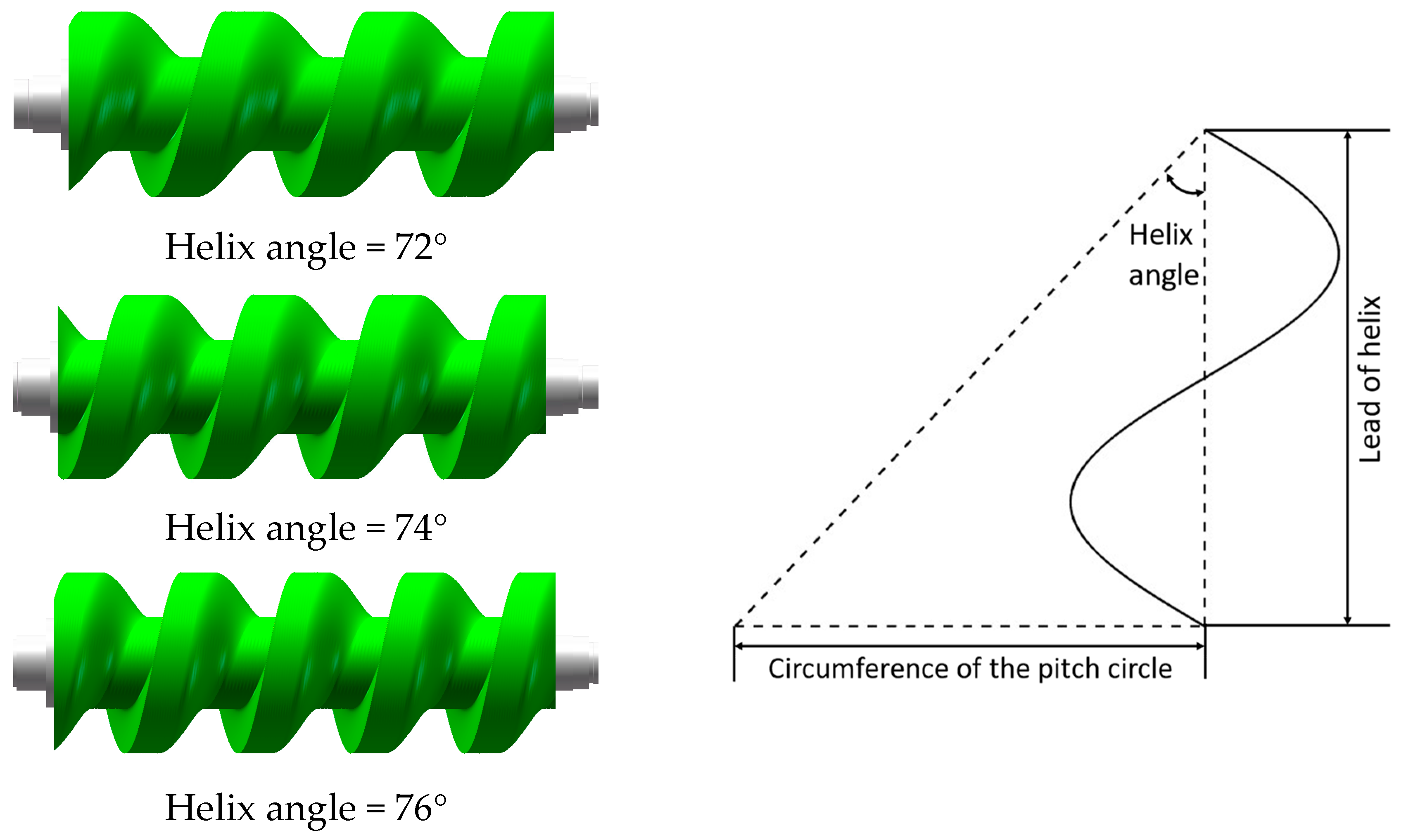
TM based on generation of series of 2D meshes in transverse planes either as rotor to casing or casing to rotor could be successfully used with a variety of CFD solvers. However, these meshes become difficult to use in calculation of the performance of vacuum pumps. There are two reasons for this, (a) the large helix angle as shown in
Figure 1 will make the rotor to casing numerical mesh extremely non orthogonal which in turn leads to difficulty in obtaining CFD results and (b) in deep vacuum the continuum principle applied in the methods used in standard CFD codes will not apply.
Similarly, experimental study of twin-screw vacuum pumps under vacuum conditions is challenging due to the large size of the high precision vacuum pressure transducers required, and the difficulty of sealing these transducers when mounted in the casing. Tuo [
15] conducted the experimental study on the working performance of one twin-screw vacuum pump under the working condition of 4 kPa suction pressure at 2700 rpm and 3000 rpm rotational speeds. So far, there is no published work on the 3D CFD simulation of a twin-screw vacuum pump under vacuum conditions. The mathematical models and software which were originally developed for twin-screw compressors can be effectively employed to simulate performance in twin-screw vacuum pumps [
16]. In this study, a typical twin-screw vacuum with the moderate helix angle in low vacuum conditions is studied. Two different type of meshes are generated with the existing grid generation method, namely casing to rotor and rotor to casing mesh. This is used to compare the quality of grids. The casing to rotor conformal mesh is then used with the Fluent solver to obtain performance predictions using parallel processing.
It was concluded that the current grid generation methods used for mapping of twin-screw machines could be used, but for the large helix angle vacuum pumps the quality of the grid may not be sufficient for accurate performance calculation. Since the grid is generated in the transverse plane the cells become highly nonorthogonal which leads to the numerical error when calculating fluxes through boundaries. According to the CFD study of twin-screw machines [
17,
18], the main fluid direction is perpendicular to the helix line especially in the clearance area. In addition, the numerical mesh in clearances is not aligned to the main direction of the leakage flow which causes numerical diffusion in clearances. As shown in
Figure 2, Vierendeels [
19] evaluated effects which the grid alignment of structured numerical meshes to the direction of the flow has on numerical diffusion of 1
st and 2
nd order numerical schemes to solve transport equation. When the grid is not aligned to the flow direction as shown in
Figure 2a, both 1
st order and 2
nd order numerical schemes will result in numerical diffusion which reduces with the mesh refinement. However, if the numerical grid is aligned to the direction of the flow, such as in
Figure 2b, than there will be no numerical diffusion and the prediction of velocities would be more accurate. This is very important for accurate prediction of leakage losses which are the main factor for efficiency of screw machines. Due to that, a different grid generation method using the normal rack procedure will be for the first time proposed in this paper. Both the main and the gate rotor coordinates will be first transformed to their normal plane, respectively, and the numerical grids will be generated in normal planes which are perpendicular to the helix line in the pitch circle of each desired normal cross section. This process is expected to make two major differences, (a) the numerical mesh will be nearly orthogonal and (b) the grid lines will be aligned to the flow through the clearances. This is expected to reduce numerical diffusion and increase accuracy and speed of calculation significantly.


