Article

Improving the Electricity Quality by Means of a Single-Phase Solid-State Transformer

1
Department of Ship’s Electrical Equipment and Automatization, Kerch State Maritime Technological University, 298309 Kerch, Russia
2
Department of Integrated Information Security, Admiral Makarov State University of Maritime and Inland Shipping, 198035 Saint-Petersburg, Russia
*
Author to whom correspondence should be addressed.
Designs 2020, 4(3), 35; https://doi.org/10.3390/designs4030035
Submission received: 3 August 2020 / Revised: 29 August 2020 / Accepted: 7 September 2020 / Published: 11 September 2020

Abstract

:
The paper describes the use of a single-phase three-stage solid-state transformer in networks with non-sinusoidal voltages in order to improve the quality of electricity. An active-inductive load was chosen as the load. The solid-state transformer was simulated by the Matlab/Simulink software. Its performance was analyzed and the parameters for optimal performance were specified. The voltage and current graphs on the load and their spectral analysis are given. Total harmonic distortion was evaluated for current and voltage. As a comparison, the operation of a classic transformer was simulated. Modeling shows that solid-state transformer copes with improving the quality of electricity better than a classical transformer. In addition to improving the quality of the load current, the solid-state transformer protects the consumer from overvoltage, voltage dips, and other transient phenomena, due to the accumulated supply of electricity in the capacitors of the DC-Bus.

1. Introduction

Transformers are widely used in power supply systems, carrying out AC voltage conversion and galvanic isolation. Recently, the use of smart grids has become more frequent. They differ from classical electric grids in that they include their own sources of energy generation and in critical situations are able to provide power to particularly responsible consumers. Large power plants and autonomous diesel–electric units, as well as high-capacity batteries, wind power stations, solar panels, hydrogen fuel cells, etc., can act as sources of electricity. The difficulty in using various sources in smart grids is the coordination of different voltage levels, which is exacerbated by the fact that the portion of the electricity is produced or stored in DC networks, and the other portion—in AC networks. A classic transformer provides direct conversion with very limited changes or improvements, so if there is any voltage asymmetry, voltage dips or frequency changes at the transformer input, the output voltage will have the same drawbacks. In addition, in order to work with direct current or alternating current networks of a different frequency, classical transformers require the use of additional equipment (inverters, rectifiers, frequency converters) [1,2].
These shortcomings can be eliminated by using solid-state transformers (SSTs) in smart power supply grids, which allow one to control the flow of electricity and improve its quality (reduce voltage dips and power surges, compensate reactive power without using any additional compensator). In addition, SSTs are smaller and make it easy to match direct and alternating currents of different voltage levels.

2. Scientific Significance of the Issue with a Brief Literature Review

Thanks to technological progress in power electronics, the use of solid-state devices has become promising for improving the quality and reliability of power supply in both transmission and distribution power systems. Recently, there has been an increase in the number of designs and in the studies related to the development of smart grids that combine the production of energy using renewable sources, batteries or other emergency power storage systems, the distribution of active and reactive components of power and the feasibility of continuous operation to maintain higher power quality [3,4]. The integration of various types of energy allows optimizing the operation of the entire energy system as a whole. For example, representative energy conversion technologies, such as energy storage technologies, can temporarily convert excess thermal/electrical energy into chemical/mechanical energy and deliver it when the system is low on energy [5].
SSTs are actively studied all over the world diversely, i.e., the transfer of electricity from an electric power source to a consumer [6], galvanic isolation (separation) between a power source and a consumer [7], improving the quality of electric power [8], matching DC and AC networks [9], developing smart grids with diverse sources of electricity of various capacities, such as solar panels, wind generators, diesel generator sets, batteries, fuel cells and others [10], creating more portable and mobile power conversion plants compared to existing ones that are especially relevant for autonomous airborne, surface [11,12,13] and underwater [14] vehicles, for electric traction systems [15], automatic compensation of reactive power in AC microgrids without using any additional compensator [16], connection to the energy storage system which allows operation as an uninterruptible power supply [17], active filtering and the protection of electrical equipment on the network side/on the consumer side [18].
SSTs have the potential to provide extra benefits compared to a traditional transformer in terms of power quality and controllability such as output voltage control, reactive power compensation, voltage regulation (flicker compensation), and power factor correction [19]. With the use of advanced control strategies, other functions can be realized; for instance, SSTs can function as a unified power quality conditioner [20]. There is a large amount of literature regarding SSTs and their applications, however they can be still considered as a young technology. The article [21] provides a list of the most pressing issues for SSTs, such as: capability of real-time communication among different SSTs within a network, the control of hybrid (DC and AC) power flow in complex networks, four wire distribution networks, modulation schemes and topologies of SSTs to achieve a small footprint and high efficiency, protections and reliability of SSTs, fault ride through the capability of SSTs, and economic viability such as the lifetime cost analysis of SSTs versus conventional transformers. Despite a large number of problems and raw technology, SSTs can be used now with limited functionality. An example of this is the use of SSTs to improve the quality and reliability of transmitted electricity. This issue is especially relevant for the private sector, where stress can sag at peak moments of consumption.

3. SST Architecture

There are a number of topologies for SSTs that allow one to apply them for specific purposes with the highest efficiency and reasonable cost. Available topologies can be divided into following three types:
The single-stage SST topology uses an AC–AC full bridge converter which converts the low frequency AC input to a high-frequency one which is then stepped down using a high frequency (HF) transformer. The output of HF transformer is further converted to power frequency using another converter. The major disadvantage of the topology is the absence of a DC link which limits the functionality of the SST.
The two-stage topology uses an AC–DC dual active bridge with a pulse-width modulation (PWM) inverter. The SST with two-stage topology avails a DC low-voltage link which can be used for the integration of distributed energy resources. This topology results in higher efficiency with a zero-voltage switching strategy. However, this type of converter suffers from the problem of high ripple current and the high sensitivity of active power flow on leakage inductance.
The three-stage SST topology comprises of a PWM rectifier, a DC–DC dual active bridge and a PWM inverter. This topology requires switching between two alternative control schemes for power flow in either direction. A more detailed comparison of various SST topologies is presented in [6,21,27,28]. It was the three-stage SST that became the most popular [28].

4. Results

Let us now evaluate how the three-stage SST will increase the quality of electricity with a high non-sinusoidality of the input voltage. The load is active-inductive in nature: R = 100 Ω, L = 1 mH.
Let us set the input voltage as
U1(t) = 311sin(314t) + 50sin(942t + 20°) + 25sin(2199t + 50°),
Internal impedance is assumed to be 0.1 Ω and 20 μH. In the case of direct power supply from this voltage source, the current will repeat the form of voltage. The input non-sinusoidal voltage will create a non-sinusoidal load current, which will create additional losses resulting in economic damage. Usually, for the sake of safety, the source of electricity and the load are separated by galvanic isolation. This case will be considered further.
The main factors that affect power quality include:
(1)
Total harmonic distortion (THD, %);
(2)
Voltage deviation index (TVD, %);
(3)
The range of voltage change (∆VLR, %);
(4)
Amount of voltage ripples (ψ, %);
(5)
Voltage non-sinusoidality coefficient (kU, %);
(6)
Coefficient of the n-th harmonic component of the voltage of odd (even) order (kU(n), %);
(7)
Negative sequence voltage ratio (k2U, %);
(8)
Zero sequence voltage ratio (k0U, %);
(9)
Duration of the power failure (ACF, s);
(10)
Impulse voltage (Uimp, kV);
(11)
Frequency deviation (Δf, Hz);
SST allows one to adjust the magnitude of the voltage and frequency, being determined by the reliability of the control system. Therefore, from all indicators of the quality of electricity, we chose only total harmonic distortion.

4.1. Modeling a Circuit on a Classic Transformer

The model of a single-phase classical transformer implemented in Simulink is shown in Figure 1.
Parameters of the classical transformer are as follows:
  • Nominal frequency 50 Hz;
  • Turns ratio 10/11;
  • Active resistance of primary winding 4 Ω;
  • Inductance of primary winding 63 mH;
  • Active resistance of secondary winding 4.5 Ω;
  • Inductance of secondary winding 72 mH;
  • Magnetization resistance 100 kΩ;
  • Magnetization inductance 3 H.
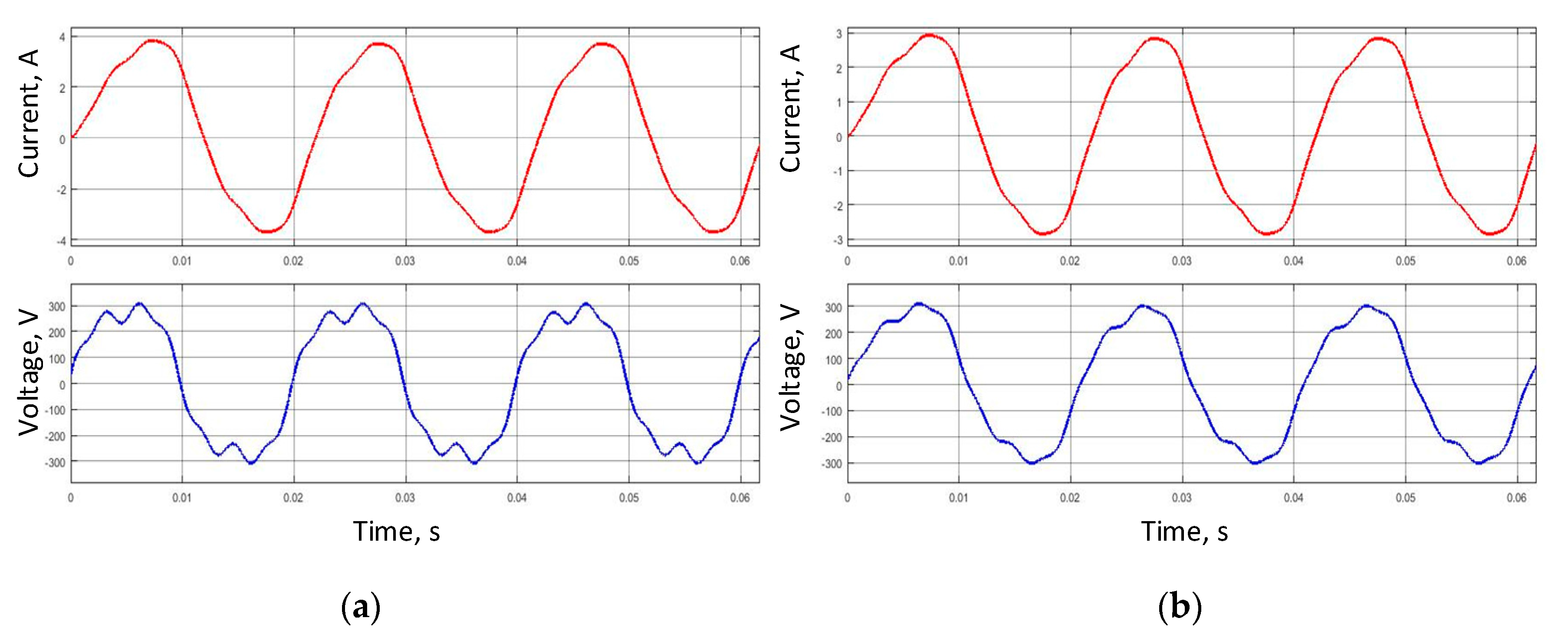
The total harmonic distortion (THD) of voltage U1(t) is 18.04%. The total harmonic distortion of input current THDI1 = 8.25%. The difference in values is that the primary winding of the transformer has a reactance and smoothens the high-frequency voltage ripples. In the secondary winding, THDU2 = 11.37%, THDI2 = 8.25%. Graphs of the input voltage and currents are presented in Figure 2a, where as the output voltage and current—in Figure 2b.
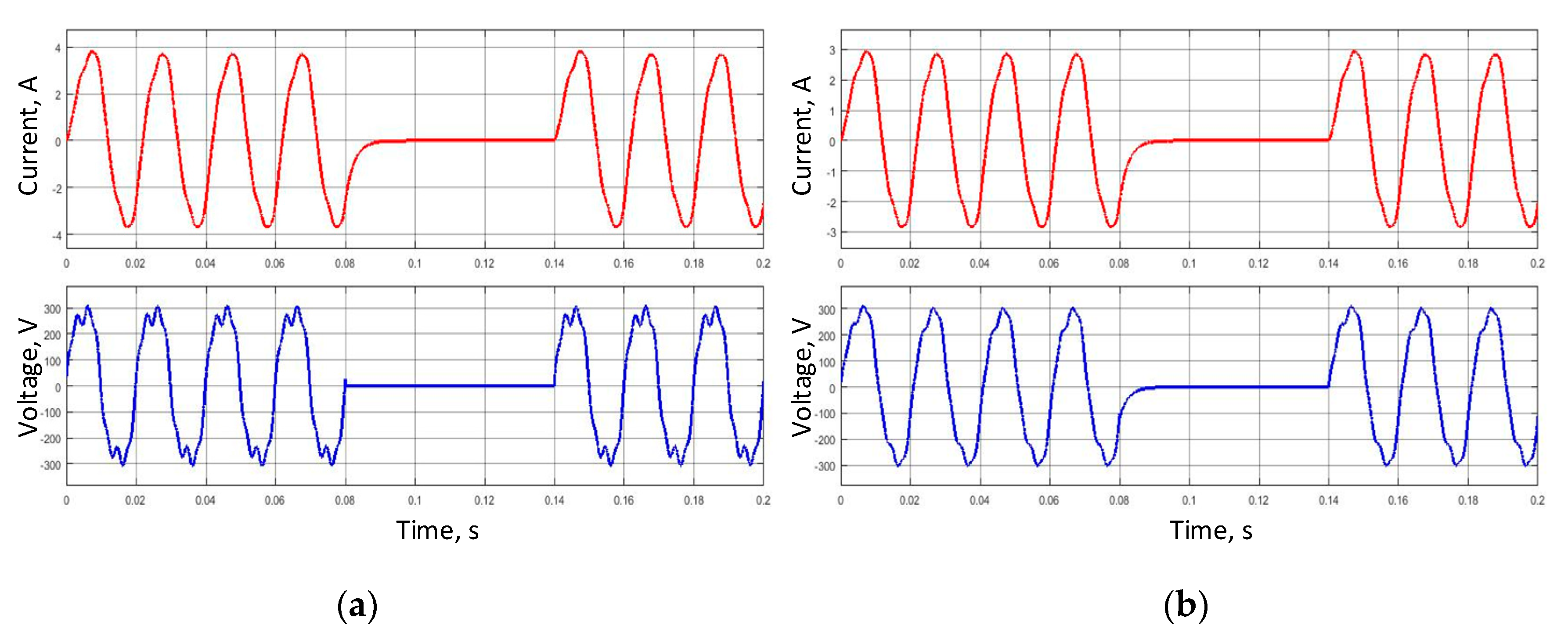
Let us evaluate the operation of the system during short-term power failure. The time of absence of voltage is three periods. The input current and voltage are shown in Figure 3a, the output current and voltage from a classic transformer are shown in Figure 3b. As can be seen from the graphs, with the disappearance of the voltage on the primary winding, the voltage on the secondary winding will also disappear.

4.2. Modeling of the Circuit with a Single-Phase SST

The single-phase SST model implemented in Simulink is shown in Figure 4.
The voltage source U1 has an active-inductive nature of the internal resistance R1. Voltage is supplied to a controllable bridge rectifier assembled with V1–V4 thyristors. In order to prevent the distortion of the input voltage due to strong distortions of the consumed current in the thyristor rectifier, it is possible to put a filter-compensating device at the SST input. The rectified voltage is smoothed by the capacitor C and then goes to the dual active bridge, consisting of an inverter based on insulated-gate bipolar transistor (IGBT) T1–T4, a high-frequency linear transformer and a rectifier based on diodes D1–D4. The resulting voltage is smoothed by the capacitor C2 and fed to the full-bridge converter, which converts to alternating voltage from direct voltage using PWM modulation. The main disadvantage of a single-phase SST as compared to a three-phase SST is that the rectified voltage after the first rectifier has a high ripple rate, i.e., the bulk capacitor must have a higher capacity in order for the SST to perform properly. Given the high voltage and large capacitance, bulk capacitors are large and expensive, which adversely affect the economic prospects of single-phase SSTs. In addition, the main load of any transformer is active-inductive; therefore, the inductance of the high frequency transformer in combination with the load inductance can create an oscillating circuit with capacitors, thereby creating unnecessary losses for heating and possible overcurrent and overvoltage.
SST was used with a small power (500 W) for the clarity of its work. In the case of a low-impedance load, the load inductance is usually large, which stretches the transients in time. Despite the fact that the SST can be divided into relatively simple blocks, which are studied quite well, the design of the SST is complicated by the fact that the SST does not work regardless of the load. Therefore, ensuring the coordinated operation of the entire complex is the main obstacle to the widespread use of SSTs, and it is necessary to design a device for the given parameters. To assess the quality of electricity, we can do this with an easily scalable model.
Consider the operation of a single-phase SST. The SST parameters are as follows:
  • Capacitance for the first stage 10 mF;
  • Nominal output frequency 50 Hz;
  • Turns ratio 10/17;
  • HF transformer frequency 1 kHz;
  • Active resistance of primary winding 0.1 Ω;
  • Inductance of primary winding 4 mH;
  • Active resistance of secondary winding 0.15 Ω;
  • Inductance of secondary winding 7 mH;
  • Capacitance for the second stage 0.1 mF.
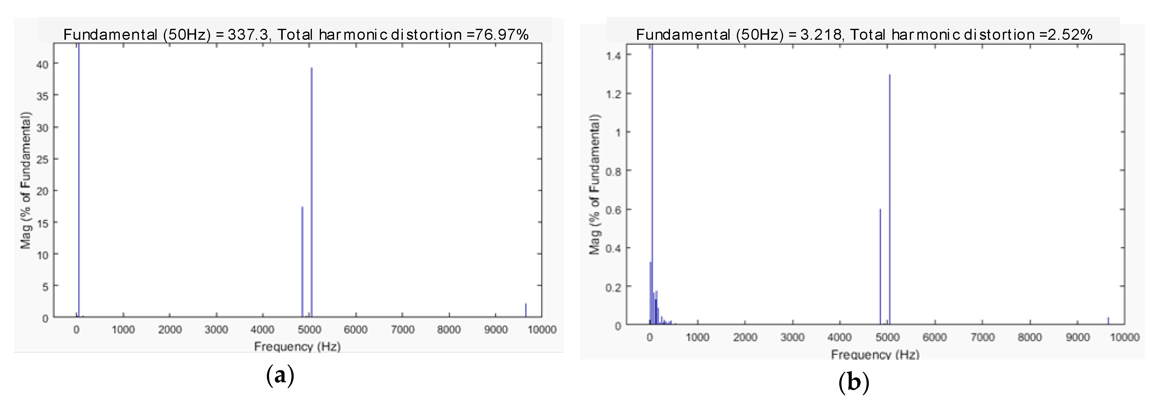
Let us analyze the values of the output current and voltage with SST: THDU2 = 77.03%, THDI2 = 2.48%. As one can see, the THD current is much better than when using a classic transformer. We can further improve the quality of the voltage by using harmonic filters, including passive ones. This issue will not be considered, and in the future, only the SST will be considered in the article without the use of input and output filters so that the comparison of SST and a classical transformer is fair and does not depend on the type and parameters of low-pass filters. The cost of passive filters is not high, so installing a filter will not greatly affect the total cost of work.
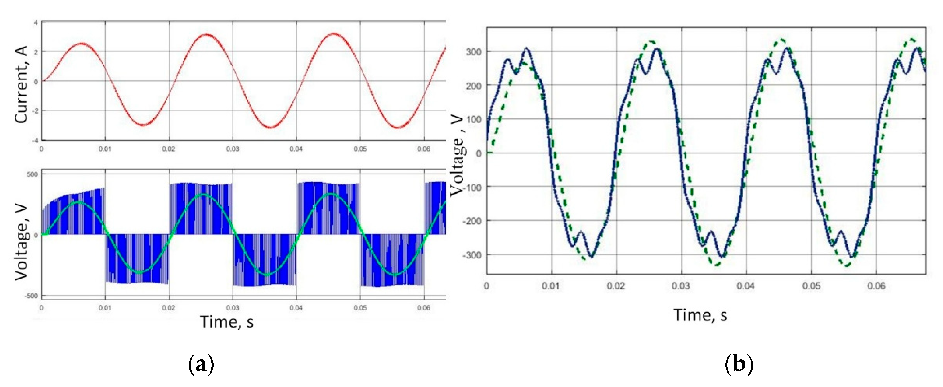
Waveform of the voltage and currents on the load are presented in Figure 5a. A comparison of the average output voltage with the SST and the non-sinusoidal input is shown in Figure 5b. The THD of the average voltage value is 1.7% and is associated with the fact that due to small ripples during voltage rectification, distortion occurs during the formation of PWM modulation owing to the fact that the amplitude of the modulated signal varies within insignificant limits.
Figure 5b shows that the first wave of the output voltage has a smaller value than the subsequent ones, which is due to the accumulation of energy in the SST reactive elements. The same elements make SST less sensitive to sharp and high-speed surges both in the direction of increase and decrease. The harmonic composition of the load voltage is shown in Figure 6a, and the harmonic composition of the load current is shown in Figure 6b.
The output voltage is modulated by means of a PWM Generator (2-Level), which generated pulses for a PWM-controlled 2-Level converter, using a carrier-based two-level PWM method. A sine wave with a frequency of 1000 Hz is supplied to the HF transformer. The carrier frequency of wiring the inverter of the second stage is 20 kHz. The PWM on the primary winding of the HF transformer and voltage on the secondary winding are shown in Figure 7. As can be seen, the voltage on the secondary winding is close to a sinusoid.
In addition to improving the quality of the current at the load, SST protects the consumer from overvoltage, voltage dips, and other transient phenomena due to the accumulated supply of electricity in reactive elements. Moreover, SST makes possible to connect DC sources with varying voltage (solar panels, wind power plants and other types of non-traditional power supply) to the network. It enables to achieve the flexibility and reliability of power supply, especially in local or independent smart grids or in systems with low power availability.
In the case of using other modeling parameters (load power, voltage levels, load power factor, etc.) SST will work similarly. When using other parameters of the load and the transformer, conclusions about improving the quality of electricity are reached. For example, for a load of 5 kW, the THD of a classic transformer will be 7.42% versus 2.39% for an SST.
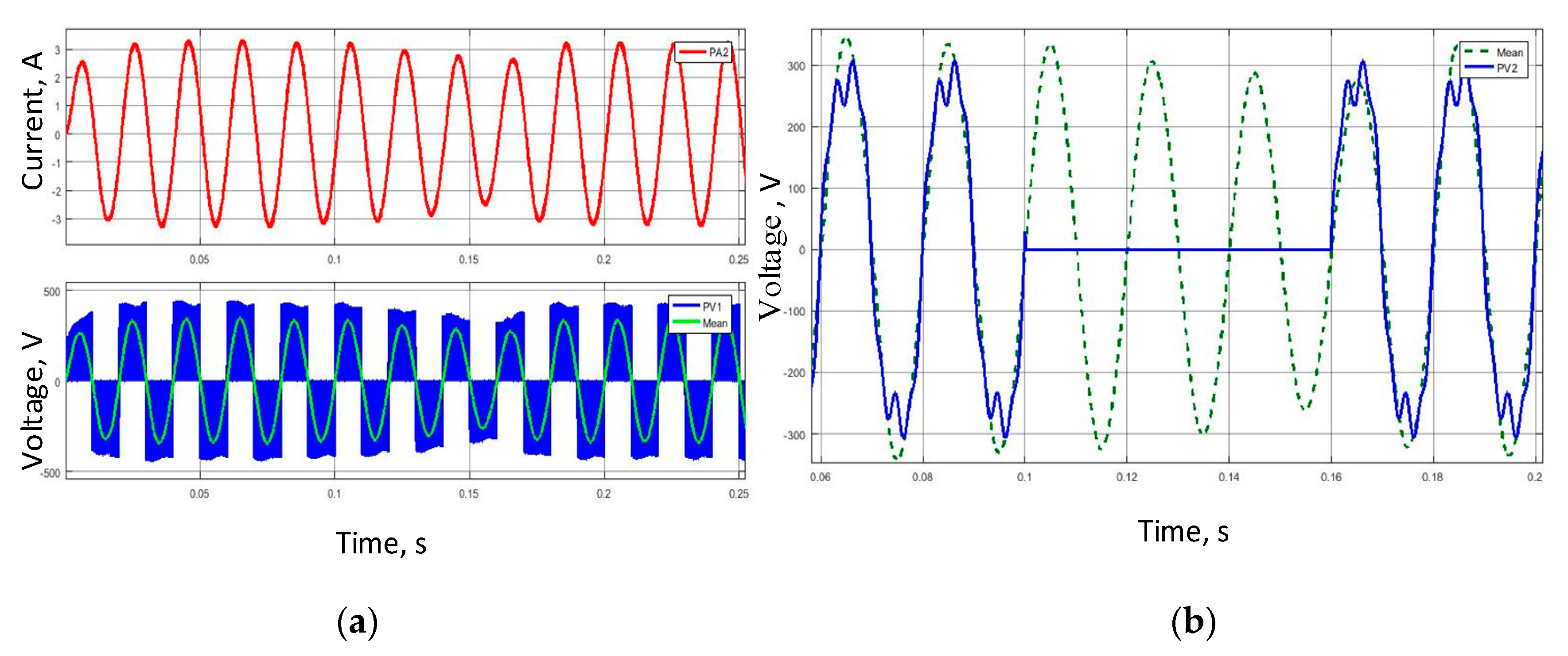
Let us see how the SST behaves in the event that the voltage disappears for a short time. We take into account that there are no sources of electricity on the DC side, i.e., transient processes at the time of voltage shutdown will occur solely due to the accumulated energy in the reactive elements of the SST. Graphs of voltage and currents on the load are presented in Figure 8a. A comparison of the average output voltage with the SST and the non-sinusoidal input is shown in Figure 8b.
Figure 8b shows that for three periods there was no voltage at the input of the SST, and the output voltage did not equal zero. The minimum value of the voltage at the SST output corresponds to the period following the moment the power was restored, which corresponds to the fourth period. The maximum subsidence voltage is 17.91%. In the second period, after power was restored, the voltage at the SST output stabilized. Thereby, we can conclude that the use of SST ensured the reliable operation of the load during the introduction/withdrawal of additional capacities with the provision of high power quality. An additional element can be a rechargeable battery (less often a solar panel, a wind generator, a fuel cell), which, together with the SST, will act as an uninterruptible power supply for a predetermined time. However, the battery does not have to be connected to the SST direct current line. If necessary, the battery can be put into operation in the event of a mains failure. Input time can be calculated in a few tenths of a second, which is satisfactory for both electromagnetic switches and solid-state switches.

5. Conclusions

As a result of the simulation performed in Matlab/Simulink, the performance of a single-phase SST at an input non-sinusoidal voltage showed that the SST improves the quality of the load current, which can be controlled using total harmonic distortion. The results of modeling the converter circuit by means of 500W-SST and a classical transformer are compared. The analysis showed a worse performance of a classical transformer (THD is 8.25%) compared to SST (THD is 2.48%). When using other parameters of the load and the transformer, conclusions about improving the quality of electricity are reached. It is shown that with a voltage dip, the SST copes with changes in the input and can maintain the output voltage until the input voltage is stabilized, or wait for the introduction of alternative sources of electricity, for example, a battery.

Author Contributions

Conceptualization, B.A.; methodology, B.A.; software, A.V.; validation, A.V. and S.C.; formal analysis, S.C.; investigation, B.A.; resources, B.A.; data curation, A.V.; writing—original draft preparation, B.A.; writing—review and editing, A.V.; visualization, A.V. and S.C.; supervision, B.A. All authors have read and agreed to the published version of the manuscript.

Funding

This research received no external funding.

Conflicts of Interest

The authors declare no conflict of interest.

References

  1. Almaguer, J.; Cardenas, V.; Espinoza, J.R.; Aganza-Torres, A.; González, M. Performance and Control Strategy of Real-Time Simulation of a Three-Phase Solid-State Transformer. Appl. Sci. 2019, 9, 789. [Google Scholar] [CrossRef] [Green Version]
  2. Chernyi, S.G.; Sergei, C. Techniques for selecting topology and implementing the distributed control system network for maritime platforms. AKCE Int. J. Graphs Comb. 2018, 15, 219–223. [Google Scholar] [CrossRef]
  3. Bignucolo, F.; Bertoluzzo, M. Application of Solid-State Transformers in a Novel Architecture of Hybrid AC/DC House Power Systems. Energies 2020, 13, 3432. [Google Scholar] [CrossRef]
  4. Shamshuddin, M.A.; Rojas, F.; Cárdenas, R.; Pereda, J.; Diaz, M.; Kennel, R. Solid State Transformers: Concepts, Classification, and Control. Energies 2020, 13, 2319. [Google Scholar] [CrossRef]
  5. Vaca-Urbano, F.; Alvarez-Alvarado, M. Power quality with solid state transformer integrated smart-grids. In Proceedings of the 2017 IEEE PES Innovative Smart Grid Technologies Conference—Latin America (ISGT Latin America), Quito, Ecuador, 20–22 September 2017; pp. 1–6. [Google Scholar] [CrossRef]
  6. Hannan, M.A.; Ker, P.J.; Lipu, M.S.H.; Choi, Z.H.; Rahman, M.S.A.; Muttaqi, K.M.; Blaabjerg, F. State of the Art of Solid-State Transformers: Advanced Topologies, Implementation Issues, Recent Progress and Improvements. IEEE Access 2020, 8, 19113–19132. [Google Scholar] [CrossRef]
  7. Zhang, X.; Xu, Y.; Long, Y.; Xu, S.; Siddique, A. Hybrid-Frequency Cascaded Full-Bridge Solid-State Transformer. IEEE Access 2019, 7, 22118–22132. [Google Scholar] [CrossRef]
  8. Avdeev, B.; Dema, R.; Chernyi, S.G. Study and Modeling of the Magnetic Field Distribution in the Fricker Hydrocyclone Cylindrical Part. Computation 2020, 8, 42. [Google Scholar] [CrossRef]
  9. Li, Z.; Wang, P.; Chu, Z.; Zhu, H.; Sun, Z.; Li, Y. A three-phase 10 kVAC-750 VDC power electronic transformer for smart distribution grid. In Proceedings of the 2013 15th European Conference on Power Electronics and Applications (EPE), Lille, France, 2–6 September 2013; pp. 1–9. [Google Scholar] [CrossRef]
  10. Sandhu, M.; Thakur, T. Issues, Challenges, Causes, Impacts and Utilization of Renewable Energy Sources Grid Integration. Int. J. Eng. Res. Appl. 2014, 4, 636–643. [Google Scholar]
  11. Verma, N.; Singh, N.; Yadav, S. Solid State Transformer for Electrical System: Challenges and Solution. In Proceedings of the 2018 2nd International Conference on Electronics, Materials Engineering & Nano-Technology (IEMENTech), Kolkata, India, 4–5 May 2018; pp. 1–5. [Google Scholar] [CrossRef]
  12. Vyngra, A.V.; Avdeev, B.A. Modeling the Operation of an Uninsulated DC-DC Converter as a Part of a Propeller Drive of Autonomous Underwater Vehicles. In Proceedings of the 2020 IEEE Conference of Russian Young Researchers in Electrical and Electronic Engineering (EIConRus), St. Petersburg and Moscow, Russia, 27–30 January 2020; pp. 2431–2434. [Google Scholar] [CrossRef]
  13. Sokolov, S.; A Zhilenkov, A.; Chernyi, S.; Nyrkov, A.; Glebov, N. Hybrid neural networks in cyber physical system interface control systems. Bull. Electr. Eng. Inform. 2020, 9, 1268–1275. [Google Scholar] [CrossRef] [Green Version]
  14. Zahedi, B.; Norum, L.E. Modeling and Simulation of All-Electric Ships with Low-Voltage DC Hybrid Power Systems. IEEE Trans. Power Electron. 2012, 28, 4525–4537. [Google Scholar] [CrossRef]
  15. Feng, J.; Chu, W.Q.; Zhang, Z.; Zhu, Z.Q. Power Electronic Transformer-Based Railway Traction Systems: Challenges and Opportunities. IEEE J. Emerg. Sel. Top. Power Electron. 2017, 5, 1237–1253. [Google Scholar] [CrossRef]
  16. Kehler, L.B.; Kaminski, A.M.; Pinheiro, J.R.; Rech, C.; Marchesan, T.B.; Emmel, R.R. Auxiliary power supply for solid state transformers. In Proceedings of the 2016 IEEE International Conference on Electronics, Circuits and Systems (ICECS), Monte Carlo, Monaco, 11–14 December 2016; pp. 193–196. [Google Scholar] [CrossRef]
  17. Bignucolo, F.; Bertoluzzo, M.; Fontana, C. Applications of the solid state transformer concept in the electrical power system. In Proceedings of the 2015 AEIT International Annual Conference (AEIT), Naples, Italy, 14–16 October 2015; pp. 1–6. [Google Scholar] [CrossRef]
  18. Farnesi, S.; Marchesoni, M.; Passalacqua, M.; Vaccaro, L. Solid-State Transformers in Locomotives Fed through AC Lines: A Review and Future Developments. Energies 2019, 12, 4711. [Google Scholar] [CrossRef] [Green Version]
  19. Krishnamoorthy, H.S.; Enjeti, P.; Sandoval, J.J. Solid-State Transformer for Grid Interface of High-Power Multipulse Rectifiers. IEEE Trans. Ind. Appl. 2017, 54, 5504–5511. [Google Scholar] [CrossRef]
  20. Sabahi, M.; Goharrizi, A.Y.; Hosseini, S.H.; Sharifian, M.B.B.; Gharehpetian, G.B. Flexible Power Electronic Transformer. IEEE Trans. Power Electron. 2010, 25, 2159–2169. [Google Scholar] [CrossRef]
  21. Abu-Siada, A.; Budiri, J.; Abdou, A.F. Solid State Transformers Topologies, Controllers, and Applications: State-of-the-Art Literature Review. Electronics 2018, 7, 298. [Google Scholar] [CrossRef] [Green Version]
  22. Chen, H.; Prasai, A.; Divan, D. Dyna-C: A Minimal Topology for Bidirectional Solid-State Transformers. IEEE Trans. Power Electron. 2016, 32, 995–1005. [Google Scholar] [CrossRef]
  23. Sahoo, A.K.; Mohan, N. Modulation and control of a single-stage HVDC/AC solid state transformer using modular multilevel converter. In Proceedings of the 2017 IEEE Applied Power Electronics Conference and Exposition (APEC), Tampa, FL, USA, 26–30 March 2017; IEEE: Hoboken, NJ, USA, 2017; pp. 1857–1864. [Google Scholar]
  24. Sabahi, M.; Hosseini, S.H.; Sharifian, M.; Goharrizi, A.; Gharehpetian, G.B. Zero-voltage switching bi-directional power electronic transformer. IET Power Electron. 2010, 3, 818. [Google Scholar] [CrossRef]
  25. Huber, J.E.; Rothmund, D.; Kolar, J.W. Comparative evaluation of isolated front end and isolated back end multi-cell SSTs. In Proceedings of the 2016 IEEE 8th International Power Electronics and Motion Control Conference (IPEMC-ECCE Asia), Hefei, China, 22–26 May 2016; pp. 3536–3545. [Google Scholar]
  26. Qin, H.; Kimball, J.W. Solid-State Transformer Architecture Using AC-AC Dual-Active-Bridge Converter. IEEE Trans. Ind. Electron. 2013, 60, 3720–3730. [Google Scholar] [CrossRef]
  27. Saeed, M.; Cuartas, J.M.; Rodriguez, A.; Arias, M.; Briz, F.; Gerges, M.S.H. Energization and Start-Up of CHB-Based Modular Three-Stage Solid-State Transformers. IEEE Trans. Ind. Appl. 2018, 54, 5483–5492. [Google Scholar] [CrossRef]
  28. Shojaei, A.; Joós, G. A topology for three-stage Solid State Transformer. In Proceedings of the 2013 IEEE Power & Energy Society General Meeting, Vancouver, BC, Canada, 21–25 July 2013; IEEE: Hoboken, NJ, USA, 2013; pp. 1–5. [Google Scholar] [CrossRef]
  29. Sanduleac, M.; Toma, L.; Eremia, M.; Ciornei, I.; Bulac, C.; Triștiu, I.; Iantoc, A.; Martins, J.F.; Pires, V.F. On the Electrostatic Inertia in Microgrids with Inverter-Based Generation Only—An Analysis on Dynamic Stability. Energies 2019, 12, 3274. [Google Scholar] [CrossRef] [Green Version]
  30. Li, Y.; Han, J.; Cao, Y.; Li, Y.; Xiong, J.; Sidorov, D.; Panasetsky, D.A. A modular multilevel converter type solid state transformer with internal model control method. Int. J. Electr. Power Energy Syst. 2017, 85, 153–163. [Google Scholar] [CrossRef]
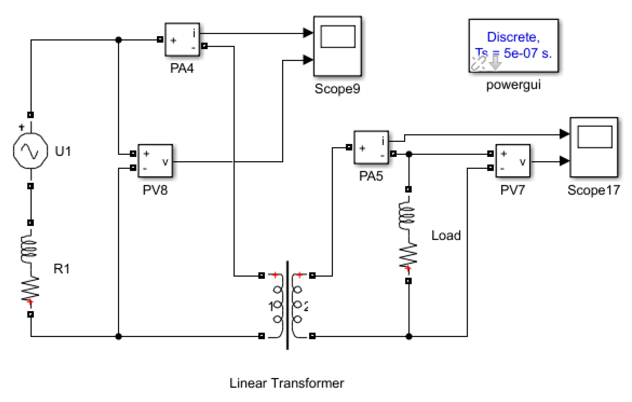
Figure 1. Simulink model of the single-phase classical transformer.
Designs 04 00035 g001
Figure 2. Modeling a circuit on a classic transformer: (a) the current and voltage on the primary winding of a classical transformer; and (b) the current and voltage on the load for a classical transformer.
Designs 04 00035 g002
Figure 3. Modeling a circuit on a classic transformer: (a) the current and voltage on the primary winding of a classical transformer; and (b) the current and voltage on the load for a classical transformer.
Designs 04 00035 g003
Figure 4. Simulink model of the single-phase solid-state transformer (SST).
Designs 04 00035 g004
Figure 5. Modeling of the circuit with a single-phase SST: (a) SST-load current and voltage (green line is the average voltage); (b) Comparison of input and average output voltage in the SST.
Designs 04 00035 g005
Figure 6. Harmonic composition of the load: (a) voltage; and (b) current.
Designs 04 00035 g006
Figure 7. Voltages on the high frequency (HF) transformer: (a) the primary winding; and (b) the secondary winding.
Designs 04 00035 g007
Figure 8. Modeling of the circuit with a single-phase SST: (a) the SST-load current and voltage (green line is the average voltage); and (b) the comparison of input and output voltage in the SST.
Designs 04 00035 g008