Intersection Sight Distance Characteristics of Turbo Roundabouts
Abstract
1. Introduction
2. Geometric Characteristics
2.1. Design of Circulatory Roadway
2.2. Intersection Sight Distance
3. Assumptions and Procedures
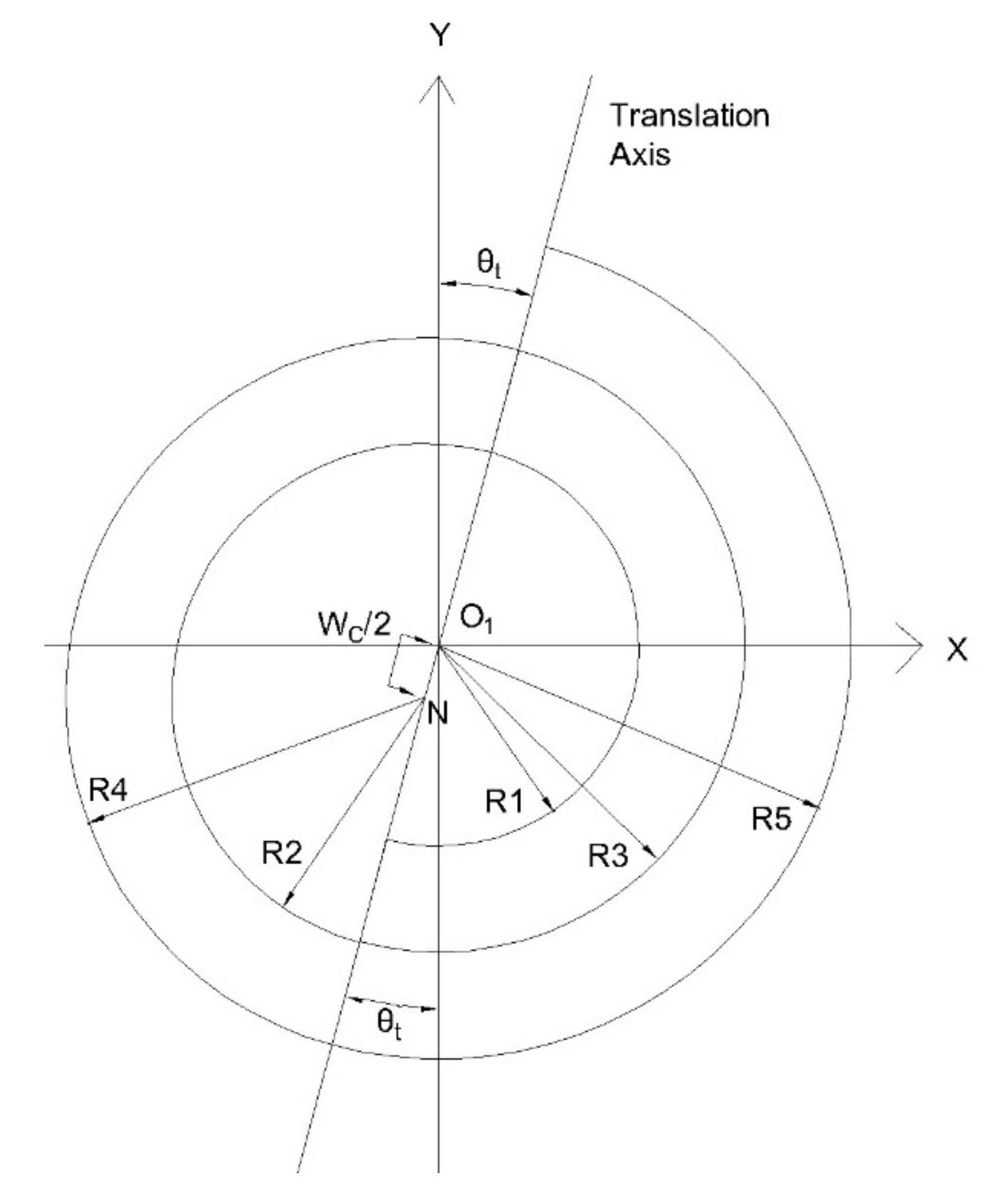
- The centre of the turbo roundabout arcs on the right side is O1 (Figure 2).
- The approach legs are intersecting the turbo roundabout exactly at a 90-degree angle.
- The critical time tc for ISD is 5 s.
- The distance from the front end of the vehicle and the driver’s eye is assumed to be 2.43 m.
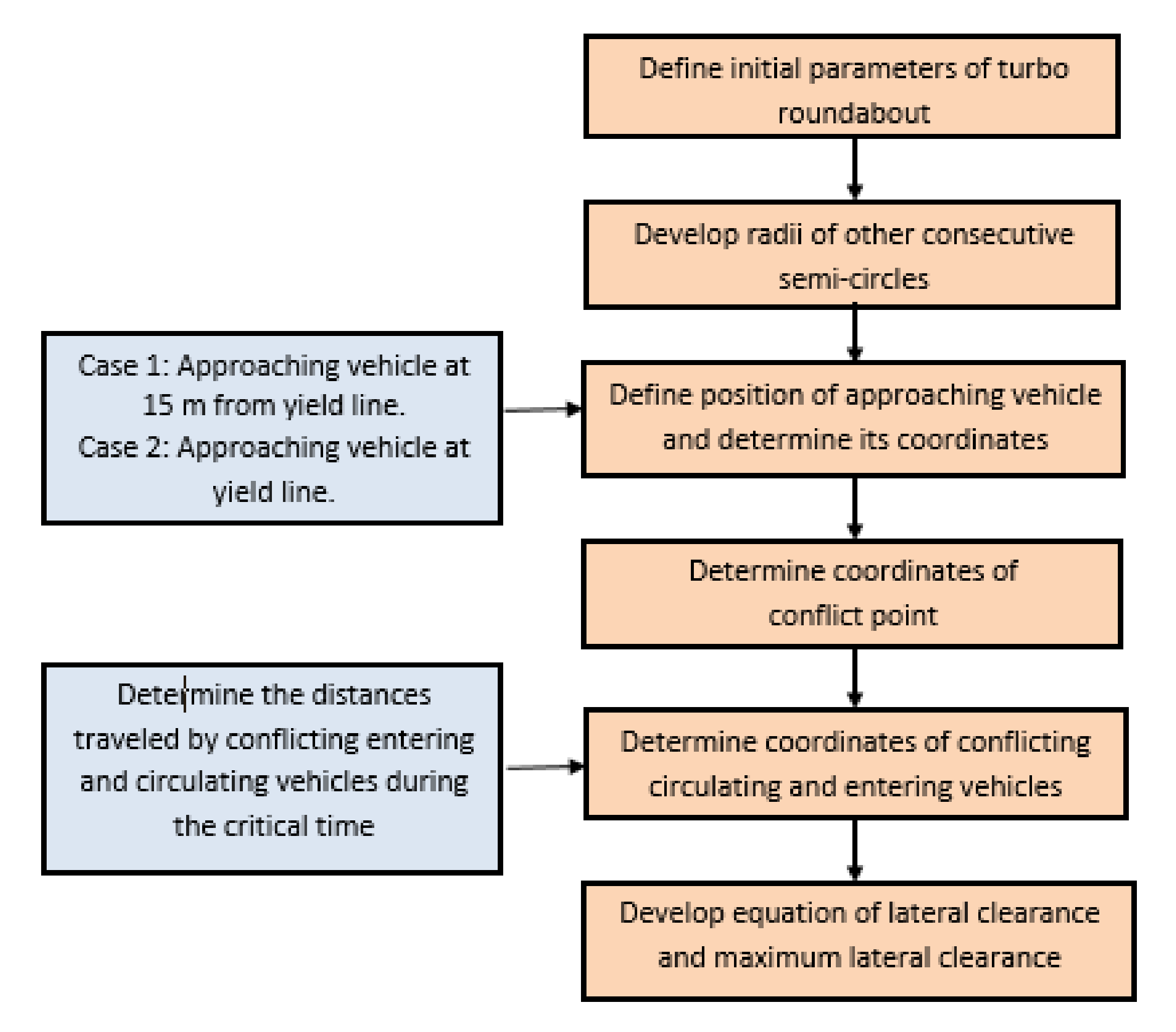
- Choose the type of turbo roundabout and determine its initial parameters.
- A swept path and speed analyses of the design vehicle are carried out. If the analyses do not satisfy the swept path or speed requirements, redesign the parameters.
- Once the initial radius and translation axis have been defined, develop the radii of other consecutive semi-circles.
- To analyse ISD, determine the coordinates of the centre of the arcs on the left and right sides of the translation axis. The coordinates of right side semicircles are assumed to be at the origin.
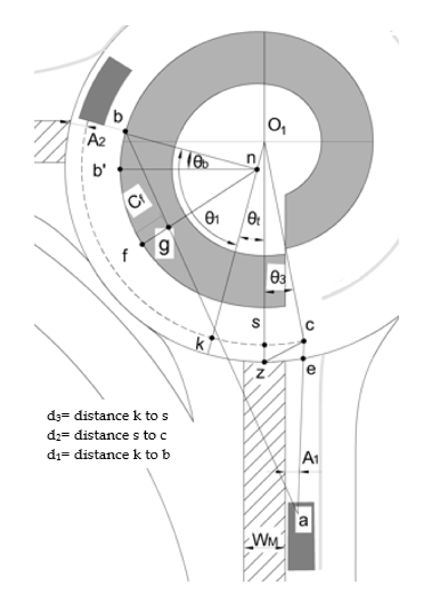
- Determine the coordinates of the approaching vehicle when it is at 15 m from the yield line (Case 1) and when it is at the yield line (Case 2).
- Determine the coordinates of the conflict point. These coordinates are important because they are needed to determine the coordinates of the conflicting-circulating and conflicting-entering vehicles.
- Determine the coordinates of the conflicting-circulating and conflicting-entering vehicles by calculating the distance travelled by the vehicle during the critical time from the conflict point following the vehicle movement trajectory.
- Determine the equation of the sightline using the coordinates of the approaching vehicle and those of the conflicting-circulating or the conflicting-entering vehicle. Then, develop an equation for the lateral clearance.
4. Sight Distance Model: Conflicting-Circulating Vehicle
4.1. Coordinates of Conflict Point
4.2. Coordinates of the Circulating Vehicle
4.3. Lateral Clearance Formulation
4.3.1. General Lateral Clearance
4.3.2. Maximum Lateral Clearance
5. Sight Distance Model: Conflicting-Entering Vehicle
5.1. Coordinates of Entering Vehicle
5.2. Lateral Clearance Formulation
6. Model Validation
7. Design Aids
8. Conclusions
- The results of the present study show that the required lateral clearance for the conflicting circulating vehicle increases when the approaching vehicle is at the yield line compared when the vehicle is 15 m before the yield line at any speed or radius. The reverse is true for the conflicting-entering vehicle.
- Intersection sight distance has been established to increase the safety of turbo roundabouts. However, providing greater sight distances than the required ISD values is not recommended as the collision rate may increase. In this regard, landscaping techniques can be used to restrict the sightlines to only ISD requirements.
- The developed method may be further used in developing safety performance functions or crash modification factors under varying roadway and traffic conditions. A detailed study on calibrating the developed equations along with its robust validation using field conditions may be considered as one of the ways forward to extend this study. In addition, reliability-based performance analysis of the developed method can be performed to improve efficiency and safety of turbo roundabouts.
- This paper has focused on modeling ISD for turbo roundabouts. The presented design aids should be helpful for designers to directly determine the lateral clearance requirements, and as such the paper helps bridge the gap between theory and practice. Future research should address several aspects, including the implications of the findings of this paper for research, practice, and society, and the economic viability of turbo roundabouts. In addition, a comparison of the AASHTO and European Union standards is warranted.
Author Contributions
Funding
Acknowledgments
Conflicts of Interest
Abbreviations
| a | position of approach vehicle |
| A1 | distance between the driver eye and outer edge of the median |
| A2 | distance between the driver eye and outer edge of the roundabout |
| b | position of circulating conflicting vehicle |
| b2 | position of entering conflicting vehicle |
| c | conflict point |
| Cf | lateral clearance for circulating conflicting vehicles |
| Cf2 | lateral clearance for entering conflicting vehicles |
| d | distance during deceleration |
| d2 | distance covered by vehicle from k to s |
| d3 | distance covered by vehicle from s to c |
| d4 | distance covered by vehicle from p′ to k |
| d5 | distance covered by vehicle from q to p′ |
| d6 | distance covered by vehicle from b2 to q |
| dcir | distance along circulatory path |
| dentry | distance along entry curve |
| D1 | sight distance of the sight triangle of the conflicting-circulating vehicle |
| D2 | sight distance of the sight triangle of the conflicting-entering vehicle |
| Lmin | distance from the yield line (15 m) |
| m | shift between inner and outer apron |
| N | centre of all the semi-circles on the left-hand side of the translation axis |
| O1 | centre of all the semi-circles on the right side of the translation axis |
| R1 | turbo roundabout initial radius with centre O1 |
| R2 | radius of the second consecutive semi-circle with centre n |
| R5 | radius of outer semi-circle of roundabout with center O1 |
| Bypass | radius of the bypass lane |
| Rn | radius of the semicircle of turbo roundabout with centre O1 |
| Rn+1 | radius of next consecutive semi-circle of turbo roundabout with centre n |
| tc | critical time |
| Vc | speed of the conflicting-circulating vehicle |
| Ve | speed of the conflicting-entering vehicle |
| Wm | width of median |
| W1 | width of the entry lane |
| Wc | circulatory roadway width |
| Z1 | centre of the radius of bypass lane |
| θT | angular distance between translation axis and y-axis |
References
- Bailey, S. Roundabouts Are Just Another Piece o the Road Becoming Popular in Canada; Toronto Star: Toronto, ON, Canada, 2016. [Google Scholar]
- Eva, P.; Andrea, K. Case study: Capacity characteristics comparison of single-lane roundabout and turbo-roundabouts. Proc. Eng. 2017, 192, 701–706. [Google Scholar] [CrossRef]
- Giuffrè, O.; Granà, A.; Marino, S. Comparing performances of turbo-roundabouts and double lane roundabouts. Mod. Appl. Sci. 2012, 6, 70–79. [Google Scholar] [CrossRef]
- Kieć, M.; Ambros, J.; Bąk, R.; Gogolín, O. Evaluation of safety effect of turbo-roundabout lane dividers using floating car data and video observation. Accid. Anal. Prev. 2019, 125, 302–310. [Google Scholar] [CrossRef]
- Tracz, M.; Chodur, J. Performance and safety roundabouts with traffic signals. Procedia Soc. Behav. 2012, 53, 788–799. [Google Scholar] [CrossRef]
- Engelsman, J.C.; Uken, M. Turbo roundabouts as an alternative to two lane roundabouts. In Proceedings of the 26th Annual Southern African Transport Conference: The Challenges of Implementing Policy, Pretoria, South Africa, 9–12 July 2007. [Google Scholar]
- Corriere, F.; Guerrieri, M. Performance analysis of basic turbo-roundabouts in urban context. Procedia Soc. Behav. Sci. 2012, 53, 622–632. [Google Scholar] [CrossRef]
- Fortuijn, L.G. Turbo roundabouts estimation of capacity. Transp. Res. Rec. 2009, 2130, 83–92. [Google Scholar] [CrossRef]
- Fortuijn, L.G.; Hendrik, G. Turbo roundabouts: Design principles and safety performance. Transp. Res. Rec. 2009, 2096, 16–24. [Google Scholar] [CrossRef]
- Flannery, A.; Elefteriadou, L.; Koza, P.; Mcfadden, J. Safety, delay, and capacity of single-lane roundabouts in the United States. Transp. Res. Rec. 1998, 1646, 63–70. [Google Scholar] [CrossRef]
- Qin, X.; Bill, A.; Chitturi, M.; Noyce, D.A. Evaluation of roundabout safety. In Proceedings of the Transportation Research Board 92nd Annual Meeting, Washington, DC, USA, 3–17 January 2013. [Google Scholar]
- Akçelik, R. Evaluating roundabout capacity, level of service and performance. In Proceedings of the ITE 2009 Annual Meeting and Exhibition, San Antonio, TX, USA, 9–12 August 2009. [Google Scholar]
- Chen, X.; Lee, M.S. A case study on multi-lane roundabouts under congestion: Comparing software capacity and delay estimates with field data. J. Traffic Transp. Eng. (Engl. Ed.) 2016, 3, 154–165. [Google Scholar] [CrossRef]
- Weber, P. Roundabout safety experience. In Proceedings of the Transportation Association of Canada Conference, Saskatoon, SK, Canada, 14–17 October 2007. [Google Scholar]
- Macioszek, E. The road safety at turbo roundabouts in Poland. Arch. Transp. 2015, 33, 2300–8830. [Google Scholar] [CrossRef]
- Rodegerdts, L.A.; Bansen, J.; Tiesler, C.; Knudsen, J.; Myers, E.; Johnson, M.; Moule, M.; Persaud, B.; Lyon, C.; Hallmark, S.; et al. Roundabouts: An Informational Guide; NCHRP Report 672; Transportation Research Board: Washington, DC, USA, 2010. [Google Scholar]
- Tollazzi, T.; Renčelj, M.; Turnšek, S. New type of roundabout: Roundabout with “depressed” lanes for right turning: Flower roundabout. Promet-Traffic Transp. 2011, 23, 353–358. [Google Scholar] [CrossRef]
- Gallelli, V.; Iuele, T.; Vaiana, R. Conversion of a semi-two lanes roundabout into a turbo-roundabout: A performance comparison. Proc. Comput. Sci. 2016, 83, 393–400. [Google Scholar] [CrossRef]
- Tollazzi, T.; Tesoriere, G.; Guerrieri, M.; Campisi, T. Environmental, functional and economic criteria for comparing target roundabouts with one or two-level roundabout intersections. Transp. Res. Part D Transp. Environ. 2015, 34, 330–344. [Google Scholar] [CrossRef]
- Tollazzi, T. Modern types of roundabouts: Trends and future expectations. In Proceedings of the III International Conference on Road Safety, Rome, Italy, 30–31 October 2014. [Google Scholar]
- Mauro, R.; Cattani, M.; Guerrieri, M. Evaluation of the safety performance of turbo roundabouts by means of a potential accident rate model. Baltic J. Road Bridge Eng. 2015, 10, 28–38. [Google Scholar] [CrossRef]
- Tollazi, T.; Zgrablić, T.; Bergoč, J.; Renčelj, M. Comparative analysis of “turbo”, “reduced-turbo”, “flower” and “semi-turbo” roundabout. Teh. Vjesn. 2020, 27, 1410–1417. [Google Scholar] [CrossRef]
- Murphy, T. The turbo roundabout a first in North America. In Proceedings of the Transportation Association of Canada Conference, Charlottetown, PEI, Canada, 27–30 September 2015. [Google Scholar]
- Guerrieri, M.; Corriere, F. Calculation of turbo-roundabouts with slip lanes. Appl. Mech. Mater. 2013, 459, 595–600. [Google Scholar] [CrossRef]
- Džambas, T.; Ahac, S.; Dragčević, V. Geometric design of turbo roundabout. Teh. Vjesn. 2017, 24, 309–318. [Google Scholar]
- Silva, A.B.; Santos, S.; Gaspar, M. Turbo roundabouts use and design. In Proceedings of the 6th Annual Confrence on Planning and Research, Coimbra, Portugal, 17 May 2013. [Google Scholar]
- American Association of State Highway and Transportation Officials. A Policy on Geometric Design of Highway and Streets; AASHTO: Washington, DC, USA, 2018. [Google Scholar]
- Vansconcelos, L.; Silva, A.B.; Seco, Á.; Rouxinol, G. Estimation of Critical Headways at Unsignalized Intersections—A Microscopic Approach. In Proceedings of the 3rd International Conference on Road Safety and Simulation, Indianapolis, IN, USA, 14–16 September 2011. [Google Scholar]
- Easa, S.M. Modeling of unsymmetrical single-lane roundabouts based on stopping sight distance. KSCE J. Civ. Eng. 2018, 23, 800–809. [Google Scholar] [CrossRef]
- Guerrieri, M.; Mauro, R.; Parla, G.; Tollazzi, T. Analysis of kinematic parameters and driver behavior at turbo roundabouts. J. Transp. Eng. Part A Syst. 2018, 144. [Google Scholar] [CrossRef]
- Easa, S.M. Design guidelines for symetrical single lane roundabouts based on intersection sight distance. J. Transp. Eng. 2017, 143, 04017052. [Google Scholar] [CrossRef]
- Easa, S.M.; Ma, Y.; Liu, S.; Yang, Y.; Arkatkar, S. Reliability analysis of intersection sight distance at roundabouts. Infrastructures 2020, 5, 67. [Google Scholar] [CrossRef]


| Parameter | Value |
|---|---|
| X0 | 0 |
| Y0 | 0 |
| R1 | 10.50 m |
| W1 | 3.19 m |
| m | 0.43 m |
| Wm | 4.00 m |
| WC | 5.15 m |
| A1 | 2.00 m |
| A2 | 1.78 m |
| Lmin | 14.95 m |
| θT | 0.26 (rad) |
| tC | 5 s |
| VC | 30 km/h |
| Ve | 60 km/h |
| No. | Variable | Symbol | Analytical | Graphical |
|---|---|---|---|---|
| 1 | x-Coordinate of approaching vehicle | xa | 3.19 | 3.19 |
| 2 | y-Coordinate of approaching vehicle | ya | −36.60 | −36.60 |
| 3 | x-Coordinate of conflict point | xC | 3.60 | 3.63 |
| 4 | y-Coordinate of conflict point | yC | −19.64 | −19.67 |
| 5 | x-Coordinate of circulating vehicle | xb | −10.17 | −10.23 |
| 6 | y-Coordinate of circulating vehicle | yb | 5.19 | 5.3 |
| 7 | Lateral Clearance at Point f | Cf | 6.57 | 6.53 |
| 8 | x-Coordinate of entering vehicle | xb2 | −61.83 | −61.9 |
| 9 | y-Coordinate of entering vehicle | yb2 | −5.21 | −5.21 |
| 10 | Lateral Clearance at Point f2 | 7.54 | 7.61 |
| VC (km/h) | Approaching Vehicle at | |
|---|---|---|
| 15 m from the Yield Line | Yield Line | |
| (a) R1 = 10.50 m | ||
| 15 | 1.4 | 1.5 |
| 20 | 1.6 | 2.6 |
| 25 | 3.6 | 5.0 |
| 30 | 6.6 | 7.9 |
| (b) R1 = 12.00 m | ||
| 15 | 1.3 | 1.4 |
| 20 | 1.6 | 2.3 |
| 25 | 3.1 | 4.5 |
| 30 | 5.8 | 7.2 |
| Speed of Circulating Vehicle, Vc (km/h) | Speed of Entry Vehicle, Ve (km/h) | |||||
|---|---|---|---|---|---|---|
| 40 | 50 | 60 | ||||
| R1 = | R1 = | R1 = | R1 = | R1 = | R1 = | |
| 10.5 m | 12 m | 10.5 m | 12 m | 10.5 m | 12 m | |
| (a) Approaching Vehicle at the Yield Line | ||||||
| 15 | −9.0 | −10.42 | −7.07 | −8.66 | −5.64 | −7.37 |
| 20 | −4.4 | −4.7 | −2.24 | −2.42 | −0.63 | −0.71 |
| 25 | −2.7 | −2.51 | −0.42 | −0.15 | 1.19 | 1.57 |
| 30 | −1.8 | −1.41 | 0.5 | 0.97 | 2.12 | 2.71 |
| (b) Approaching Vehicle 15 m from the Yield Line | ||||||
| 15 | −9.2 | −11.3 | −6.5 | −9.0 | −4.5 | −7.1 |
| 20 | −2.7 | −3.4 | 0.7 | −0.1 | 3.2 | 2.5 |
| 25 | 0.1 | −0.3 | 3.5 | 3.3 | 6.1 | 6.0 |
| 30 | 1.4 | 1.4 | 5.0 | 5.1 | 7.6 | 7.8 |
| Speed of Circulating Vehicle, Vc (km/h) | Speed of Entry Vehicle, Ve (km/h) | |||||
|---|---|---|---|---|---|---|
| 40 | 50 | 60 | ||||
| R1 = | R1 = | R1 = | R1 = | R1 = | R1 = | |
| 10.5 m | 12 m | 10.5 m | 12 m | 10.5 m | 12 m | |
| (a) Approaching Vehicle at the Yield Line | ||||||
| 15 | −7.3 | −8.8 | −5.4 | −7.0 | −4.0 | −5.7 |
| 20 | −2.8 | −3.0 | −0.6 | −0.8 | 0.9 | 0.9 |
| 25 | −1.0 | −0.9 | 1.2 | 1.4 | 2.8 | 3.1 |
| 30 | −0.1 | 0.2 | 2.2 | 2.5 | 3.7 | 4.3 |
| (b) Approaching Vehicle 15 m from the Yield Line | ||||||
| 15 | −7.5 | −9.7 | −4.8 | −7.3 | −2.8 | −5.5 |
| 20 | −1.0 | −1.7 | 2.2 | 1.5 | 4.7 | 4.0 |
| 25 | 1.6 | 1.3 | 5.0 | 4.8 | 7.63 | 7.5 |
| 30 | 3.0 | 3.0 | 6.5 | 6.6 | 9.1 | 9.3 |
Publisher’s Note: MDPI stays neutral with regard to jurisdictional claims in published maps and institutional affiliations. |
© 2021 by the authors. Licensee MDPI, Basel, Switzerland. This article is an open access article distributed under the terms and conditions of the Creative Commons Attribution (CC BY) license (http://creativecommons.org/licenses/by/4.0/).
Share and Cite
Salwan, A.; Easa, S.M.; Raju, N.; Arkatkar, S. Intersection Sight Distance Characteristics of Turbo Roundabouts. Designs 2021, 5, 16. https://doi.org/10.3390/designs5010016
Salwan A, Easa SM, Raju N, Arkatkar S. Intersection Sight Distance Characteristics of Turbo Roundabouts. Designs. 2021; 5(1):16. https://doi.org/10.3390/designs5010016
Chicago/Turabian StyleSalwan, Akshay, Said M. Easa, Narayana Raju, and Shriniwas Arkatkar. 2021. "Intersection Sight Distance Characteristics of Turbo Roundabouts" Designs 5, no. 1: 16. https://doi.org/10.3390/designs5010016
APA StyleSalwan, A., Easa, S. M., Raju, N., & Arkatkar, S. (2021). Intersection Sight Distance Characteristics of Turbo Roundabouts. Designs, 5(1), 16. https://doi.org/10.3390/designs5010016


