Article

A Simplified Approach for the Determination of Penetrant Residual Velocity for Penetration Processes

by
Abdulaziz S. Alhulaifi
Department of Mechanical Engineering Technology, Yanbu Industrial College, Yanbu Al Sinayiah 21477, Saudi Arabia
Designs 2022, 6(1), 19; https://doi.org/10.3390/designs6010019
Submission received: 28 January 2022 / Revised: 10 February 2022 / Accepted: 11 February 2022 / Published: 18 February 2022

Abstract

:
The study’s main aim was to predict the penetrant residual velocity, with it being a vital output parameter in the projectile target interaction. The ballistics have been probed on a wide spectrum of impact velocities for different applications. Determination of the residual velocity by analytical methods entails the use of the impulse momentum principle, and the process is further challenged by the necessary inclusion of various variables that directly affect the calculation of the residual velocity. These problems can be overcome by adopting a non-dimensional approach by determining the combination of variables required for the penetration process by carrying out and validating the non-dimensionalization of the pertinent variables. The process discussed in this study provides a reasonable correlation of the non-dimensional parameters, which was used to estimate and validate penetrant residual velocity. A generalized solution predicting the penetrator residual velocity for a wide range of materials for a variety of impact velocities is proposed. The result of this correlation was validated against the published data, and the method was largely in agreement, showing the robustness of the proposed finding.

1. Introduction

Ballistics have been investigated for many years in a wide spectrum of impact velocities, among the myriad of applications of ballistics, such as cold spray deposition, delivery of microparticles into human skin, ballistic armor, etc. Most of the applications focus on improving projectiles or enhancing the target resistance. The cold spray deposition [1] and delivery of micro-particles into human skin through ballistic [2] processes involves the acceleration of solid particles to high velocities using supersonic carrier gas and then penetrating the target with a sufficient impact velocity. There are several reports on the cold spray and ballistic delivery of micro-particles using a uniform particle shape [3,4,5,6,7]. However, other ballistics with a different nose shape might influence the non-deforming projectile ability to penetrate into a target [8,9]. Gupta et al. [10] reported the effect of the projectile nose shape impacting different thicknesses of aluminum plates experimentally and numerically. They found that the most efficient penetrators for thin plates are the ogive-nosed projectiles. However, for thick plates, blunt-nosed projectiles perform well by perforating the target plates with the least energy. Rosenberg and Dekel [11] obtained an analytical model for predicting the ballistic limit of ductile plates impacted by sharp-nosed, rigid projectiles. Their model distinguished between dishing and hole enlargement deformation mechanisms for thin and thick plates. Madhu et al. [12] evaluated the effect of the oblique and normal impact of armor-piercing on single and multilayer plates to drive empirical equations that were used to compute the residual velocity. Because of the empirical nature of its equation, as expected, it is mostly not suitable for all penetrant shapes against all types of targets. On the other hand, Philip et al. [13] described a set of dimensionless groups as the product of the specific fiber toughness and strain wave velocity, which can evaluate the target performance, mainly the fiber, to reduce the penetrant residual velocity. Moreover, Bao et al. [14] conducted a numerical simulation to predict the ballistic properties of hybrid CFRP/AFRP laminates with reliable comparison to the experimental data. Both results recommended that increasing the content of CFRP increases the flexural properties of hybrid CFRP/AFRP laminates. The dimensional analysis methodology was also conducted by Song et al. [15] to predict the residual velocity of the projectile, where dimensionless residual velocity relationship is obtained and verified, in the range of normalized target thicknesses, mainly ranging from half to full diameters of the projectile. Malik et al. [16] provided a novel approach to enhance the ballistic impact resistance of Mg alloy through the “cross pre-compression” technique. Furthermore, the components of Mg alloys were subject to high strain rate compression [17], and excessive microstructure features were characterized by EBSD, TEM, SEM, and OM of the deformation behavior of Mg alloys, where the standard 7.62 mm soft steel core projectile at a standard velocity of 830 m/s, completely perforated the Mg substrate [18]. Other lightweight materials such as AA 6061-B4C composites have been fabricated by powder-metallurgy and hot-extrusion techniques [19]. Metal matrix composites were reinforced with 5 wt%, 10 wt%, 15 wt%, and 20 wt% B4C. The matrix structure had uniform reinforcement particle distribution, and higher relative density, hardness, and tensile strength values were measured among the specimens. The key parameter that influences the armor material efficiency and characterizes a physical limit between penetration depth and perforation of the target is the penetrant residual velocity. Parameters were determined from complicated numerical software in earlier conducted studies, such as ABAQUS/Explicit version 6.14 software (Hibbitt, Karlsson & Sorensen, Inc., Pawtucket, RI, USA) [20], or by carrying out expensive trials to measure the penetrant residual velocity. However, the main purpose of this study was to estimate and validate the penetrant residual velocity by correlating various parameters in non-dimensional forms. These correlations can optimize the time involved in estimating the output parameters such as the penetrant residual velocity instate of running a computational model or conducting costly experiments.

2. Residual Velocity Determination

Residual velocity can be determined by applying one-dimensional conservation of momentum along the axial direction. Before applying Newton’s second law, some assumptions should be taken into account to determine the residual velocity. In this study, we apply the same assumption that has been used by Ghaseminia et al. [21] to formulate the problem. The scheme of the problem is shown in Figure 1.
Where L, X, L-X, t, d, u   , and v are the rod length, deform length, undeformed length, plate thickness, penetration depth, instantaneous penetration velocity of the rod nose, and speed of the undeformed portion, respectively. During penetration, the cross-section area A and the density of the undeformed rod ρ p remain constant; thus, the mass of the undeformed rod M can be described as:
M = ρ p A l
where the undeformed length l can be seen to be equal to L-X (Figure 1).
At the time of penetration, the rod nose will erode, which will cause a reduction in the length of the rod, resulting in a change of the rod mass that can be written as:
M ˙ = ρ p A l ˙
where M ˙ is the rate change of the rod mass and l ˙ is the erosion rate.
To determine the erosion rate, which is the decrease of the rod length with respect to time, one has to determine the change of the rod length by defining the movement of the penetrant nose and the rigid portion using the time interval Δ t .
Thus, the nose end of the rod will move a distance u Δ t and the rigid portion will move a distance v Δ t .
Therefore, the change of the rod length can be written as:
Δ l = u Δ t v Δ t
Dividing both sides by Δ t , Equation (3) becomes:
l ˙ = u v
By substituting Equation (2) into Equation (4), it can be rewritten as:
u v = M ˙ ρ p A
where Equation (5) depicts if there is no change of the mass M ˙ = 0, then u = v thus, rigid body penetration. To derive the equation of motion, the principle of impulse momentum must be applied to the undeformed portion of the rod, which can be stated as follows:
Momentum at time ( t + Δ t ) —Momentum at time (t) = F Δ t .
This will lead to the following:
ρ p A ( Δ X ) u + ρ p A ( L X Δ X ) ( v + Δ v ) = F Δ t
Equation (6) can be further reduced to the following equation by neglecting the high order.
( u v ) Δ X + l Δ v = F ρ p A Δ t
Dividing both sides by Δ t , Equation (7) becomes:
( u v ) X ˙ + l Δ v Δ t = F ρ p A
Since l was previously defined to be equal to L-X, then applying the derivative with respect to X, we get:
l ˙ = X ˙
By substituting Equations (9) and (5) into Equation (8), it can be rewritten as:
l d v d t M ˙ ρ p A l ˙ = F ρ p A
By multiplying both sides by ρ p A and substituting Equation (2) into Equation (10), the equation of motion for the undeformed portion of the rod can be written as follows:
M d v d t = M ˙ 2 ρ p A F
Equation (11) shows the forces acting on the projectile while impacting the target. As described by Dehn [22], the right side of Equation (11) is linked to each other, where the magnitude of the mass loss rate depends on the kind of target being penetrated. Thus, the right side of Equation (11) is negative, where in most cases, the target decelerates the penetrant. For simplicity and to determine the residual velocity of the penetrant, we assume that the projectile has a spherical shape. Therefore, a projectile with an aspect ratio (length to diameter ratio) ≤ 1 does not erode [22]. Thus, M ˙ = 0, and Equation (11) can be reduced to the following:
M v d v d x = F
Now, the force exerted by the target can be divided into (Fy) yield force, (Ff) fractional resistive force, and (Fi) an internal resistive force of the target material, where all of them oppose the motion of the penetrator. In fact, in this study, (Ff) is neglected based on Dehn’s findings [22], and the most important forces for a solid target are (Fy) and (Fi) because the bonds must be broken and the target material must be moved. Based on these findings, Equation (12) becomes:
M v d v d x = ( F y + F i )
The yield force and internal resistive force are given by Equations (14) and (15), respectively:
F y = 3 A σ y
F i = 1 2 ρ t A v 2
where the σ y and ρ t are the yield stress and the density of the target.
By substituting Equations (14) and (15) into Equation (13) yields:
M v d v d x = 1 2 ρ t A v 2 3 A σ y
Equation (16) can be solved by the separation of variables:
V r = V i 2 + 6 σ y ρ t e ρ t A t M 6 σ y ρ t 1 2
where Vr, Vi, and t are the penetrant residual velocity, penetrant impact velocity, and the plate thickness, respectively. Penetration depth (d) can be solved from Equation (16) by the separation of variables.
d = M ρ t A ln 1 2 ρ t V i 2 + 3 σ y ln 3 σ y
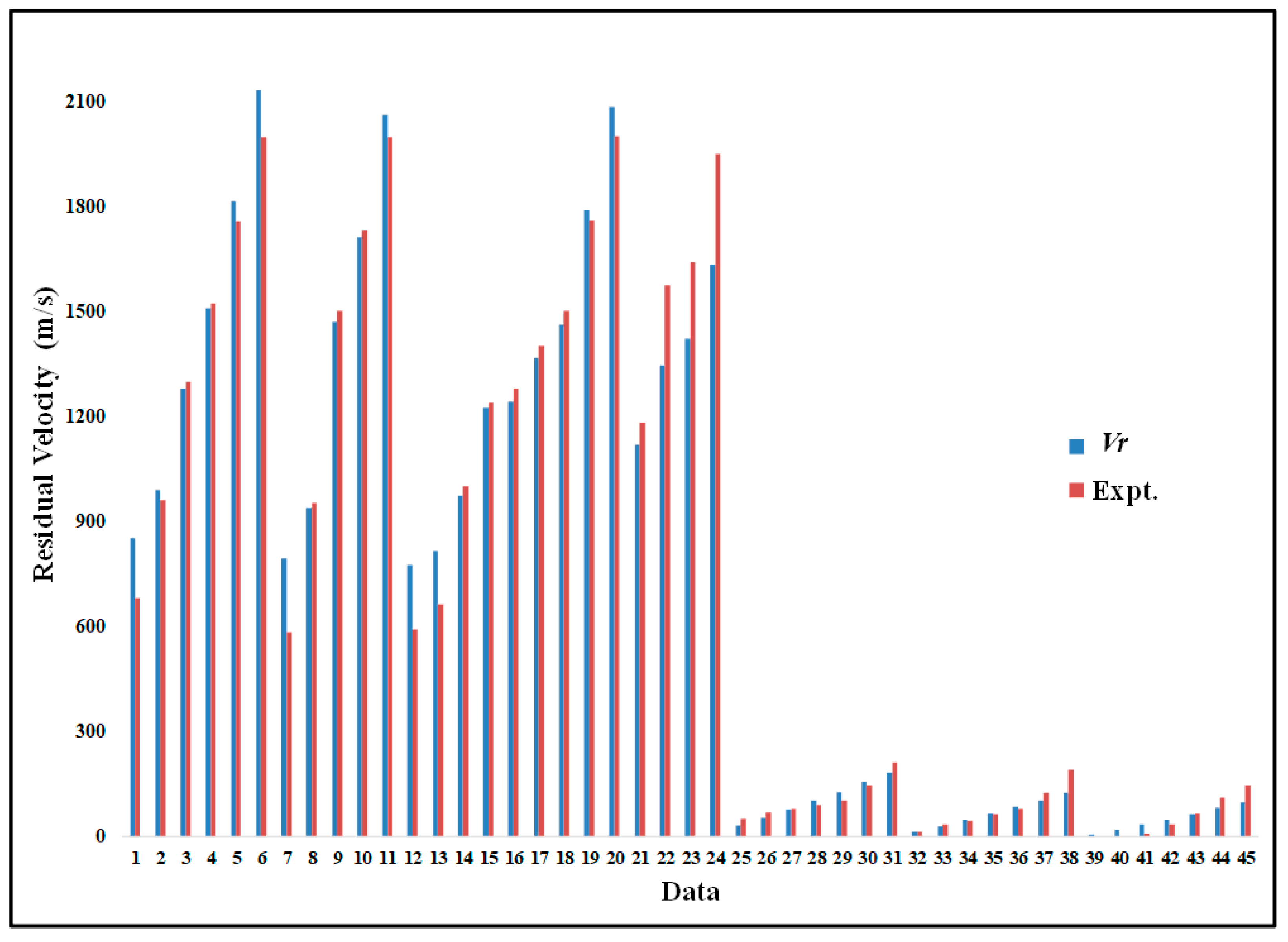
Equations (17) and (18) cannot be applied for a wide range of projectile shapes but are limited to spherical projectiles, such as delivering vaccine powder into the human body without a needle injection [23]. However, to examine the validity of Equation (17) and to compute the residual velocity for different projectiles geometry, experimental data have been extracted from published articles [24,25] and compared with Equation (17), as depicted in Figure 2, which shows the comparison of Equation (17) with published data for the residual velocity determination. It can be seen that Equation (17) follows the same patterns of the published data with a high magnitude, especially when we compare that with the data extracted from [25]. However, Equation (17) represents the residual velocity for a high-impact velocity, as shown in comparison with data extracted from [24], even with different plate thicknesses and impact velocities.
The determination of residual velocity is a challenging task requiring running finite element software such as ABAQUS; wherein multiple parameters are involved in the penetration process. In fact, numerical modeling for the determination of residual velocity is cumbersome, necessitating improved analysis techniques. Therefore, non-dimensional analyses can offer a general solution that predicts the penetrator residual velocity for a wide range of materials under an extensive range of impact velocities.

3. Non-Dimensional Study for Penetrant Residual Velocity

The penetrant residual velocity is one of the most crucial output parameters in the penetration process. Many independent variables can influence the penetrant residual velocity, like penetrators/target properties and the impact velocity. It is imperative to single out the independent parameters (inputs) that profoundly affect the primary dependent variable (output), i.e., the penetrant residual velocity, to understand the penetration process. The non-dimensional form of these parameters is essential to reduce the dimension of the parameter space and cover a wide range of penetration process operations. To determine which of these independent parameters significantly influenced the penetrant residual velocity, they were cast in a non-dimensional form, and the Buckingham Pi Theorem was used to define the number of non-dimensional parameters required.

Buckingham Pi Theorem

In the absence of any governing equation that directly describes the penetrant residual velocity, functional relationships were simplified using dimensional analyses. Buckingham Pi theorem was used to form suitable dimensionless groups that represent physical influences. The theorem assembles the dimensional physical parameters the define the system into smaller dimensionless groups. The relationship among the different groups can be established empirically, like the relation between the drag coefficient and the Reynolds number.
Bridgman’s [26] statement of the Pi Theorem says, “If the equation F(q1,q2,q3…qn) = 0 is complete, the solution has the form f1,π2…πn-k) = 0, where π terms are independent products of the parameters q1, q2, etc., and are dimensionless in the fundamental dimensions”. The number of Pi terms that appear in the solution equation has been reduced from n to (n-k), where k is equal to the number of the fundamental dimensions such as (M, L, T, …, etc.).
Penetrant residual velocity being a function of density ratio and a multitude of other independent parameters, and a dimensional function for penetrant residual velocity can be written in the form:
V r f A , t , σ t , V i , M p , ρ t , ρ p
The seven independent parameters are: A penetrant area projected on the target, t target thickness, σ t target yield stress, Vi penetrant impact velocity, Mp penetrant mass, ρ t target density, and ρ p penetrant density.
The following set of Pi can be calculated by subtracting the fundamental dimensions (3) from the number of variables (8), as shown below using the Buckingham Pi theorem:
π 1 = V r σ t ρ t ; π 2 = ρ t ρ p ; π 3 = σ t V i 2 ρ t ; π 4 = t 3 ρ t M p ; π 5 = A t 2
Although the Pi theorem mandates that π1 (the non-dimensional penetrant residual velocity) ought to be a function of four (4) independent Pi terms, the second Pi (density ratio) influences the penetrant residual velocity. Furthermore, the third Pi plays a significant role in the prediction of penetrant residual velocity, showing the force ratio yield force to a resistive internal force of the target material. Furthermore, the fourth and fifth Pi terms above define a mass ratio of the target to the penetrant. Multiplying all Pi terms together, the new Pi term was defined by the symbol Eta (η), given by the following non-dimensional relation:
η = σ t 1 2 V i 2 ρ t 0.89 t 3 ρ t M p A t 2 1.19 ρ t ρ p 1.07
With this new parameter, the following non-dimensional relation was proposed:
V r σ t ρ t = f η
The scaled penetrant residual velocity equation (Equation (21)) provides for only one independent non-dimensional parameter defining it, and the published experimental data [24,25] for all runs shown in Figure 2 were drawn into the outlines as indicated in Figure 3.
Figure 3 shows the non-dimensional result predicting the penetrant residual velocity. The results represent a single curve with one scaled equation. Moreover, the Eta (η) has a profound influence in fitting the data into a single curve. In fact, the function of Eta (η) describes the non-dimensional penetrant residual velocity, where the scale is the pseudo speed of the sound of the target. The functions obviously affirm that for low Eta (η), high penetrant residual velocity is obtained, and vice versa. Moreover, the pseudo speed of the sound of the target describes the stiffness of the target material, where the faster indicates a low penetrant residual velocity and vice versa. The reason for not scaling with the actual speed of sound is due to the shortage of published data. As mentioned previously, the main objective of this study was to define simple empirical equations that can be used to determine the penetrant residual velocity for a wide range of applications. Thus, the use of Eta (η) as the appropriate independent variable provides great means in controlling the penetrant residual velocity over a wide range. To increase the penetrant residual velocity, Eta (η) must be kept at the lowest value. However, to decrease the penetrant residual velocity, Eta (η) must be unity. To control the unity of Eta (η) with an assumption of the penetrant mass equal to the mass of the projected target plate, internal resistive force must be at the lowest value. It makes sense and indicates that the resistive internal force is not reaching the value of the yield or the compression force and that the bonds within the material will not be broken. Furthermore, if the value of the internal resistive force overcomes the yield force, bonds will be broken and, thus, high penetrant residual velocity can occur. That can also be applied to the mass ratio—if the penetrant mass is higher than the projected target mass, penetrant residual velocity increases, and vice versa. To extract the function from the previous plot, curve fitting must be applied to the previous plot. The curve fitting was performed with the SigmaPlot v.6 software (Systat Software Inc., San Jose, CA, USA). The power three parameters function was used to get the best curve fitting, as can be seen from Figure 3.

4. Discussion

A plethora of published results have attempted to calculate the penetrant residual velocity in a dimensional form, either numerically or analytically. These scientific studies have been undertaken to identify the appropriate dimensional parameters or variables that greatly affect the penetrant residual velocity, substantiated by experimental findings. The relevant dimensional parameters were identified in the current study as the penetrant area projected on the target, target thickness, target yield stress, penetrant impact velocity, penetrant mass, target density, and finally, the penetrant density. By knowing these parameters, Eta (η) functions can be used to calculate the penetrant residual velocity. To test the curve fit equation defined above, it was used to compute penetrant residual velocity with input data from various published studies. In fact, the first attempt to apply the Eta (η) function was with the same data examined previously with Equation (17) to compare the Eta (η) function with Equation (17). The penetrant residual velocity in Figure 4 extracted from the curve fitting equation shows a good agreement with experimental data in both metal and Kevlar29/Epoxy-AL2O3 composite material targets. Furthermore, the curve fitted equation showed a good agreement with experimental data compared to Equation (17), especially for composite target materials.
Data was also taken from Chen et al. [27] for additional comparison. They attempted to use the energy conservation principle to compute the residual velocity of hemispherical projectile shape impacting thin steel plates at low velocities by establishing a new analytical model.
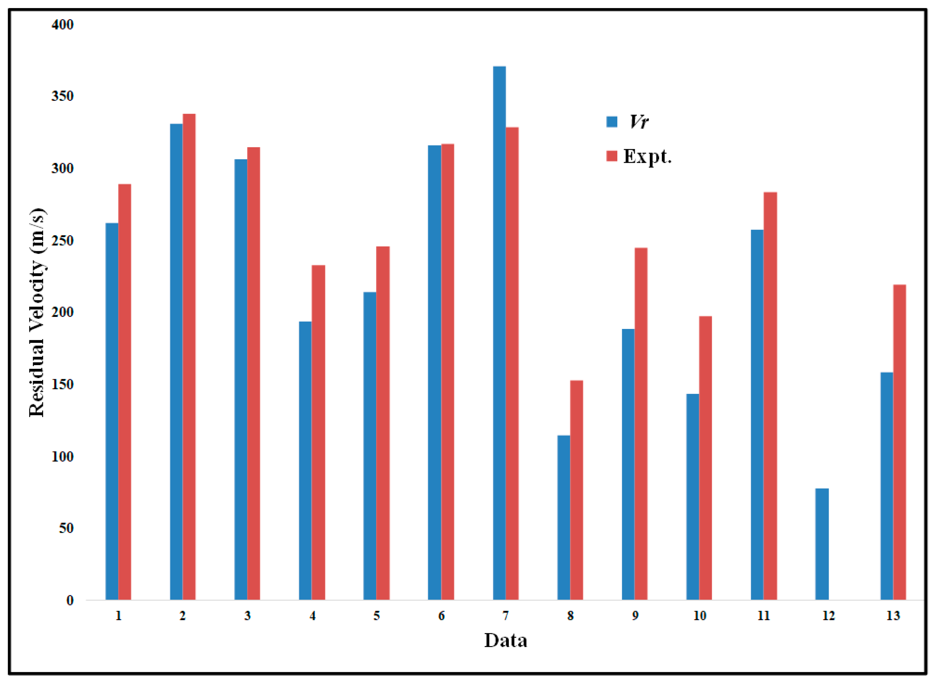
Figure 5 shows an excellent agreement between the curve fit predictions and the experimental data of Chen et al. [27], which also agreed very well with the analytical model established in this study, and a solitary straightforward equation predicted the penetrant residual velocity in spite of different projectile geometry and a wide range of plate thicknesses. The correlation produced for the data used in this study showed exceptional agreement in calculating the penetrant residual velocity. The results show that the correlation was apt in predicting the penetrant residual velocity for a wide range of different material properties. These correlations are immensely valuable to the professionals involved in designing armor, as the correlation offers a swift dependable means to determine the penetrant residual velocity and the parameters required to get the desired results without the need of going into high-end numerical modeling.

5. Conclusions

In the penetration process, the most vital output parameter is the penetrant residual velocity for the projectile impacting the target. To compute the penetrant residual velocity analytically, the equation of motion must be derived from the principle of impulse momentum. Then, the penetrant residual velocity can be calculated by applying the separation of the variables to the equation of motion. However, the analytical solution cannot predict penetrant residual velocity for a wide range of material properties, as shown previously. Thus, as a result of this research, a novel procedure has been introduced to estimate the penetrant residual velocity in a simple and very reliable way. A non-dimensional correlation that is generally applicable was obtained by identifying and examining a group of non-dimensional parameters validated against a body of published data. The practitioners of the penetration process can save a considerable amount of time and effort to estimate the output parameters such as penetrant residual velocity for a given set of independent parameters by using these correlations. These estimates can be obtained without the need to run lengthy, sophisticated finite element models or conduct complicated experiments (e.g., laser Doppler velocity measurements) on a case-by-case basis.

Author Contributions

The author confirms sole responsibility for the following: study conception and design, methodology, data collection, validation, analysis and interpretation of results, and manuscript preparation. Author have read and agreed to the published version of the manuscript.

Funding

This research received no external funding.

Institutional Review Board Statement

Not applicable.

Informed Consent Statement

Not applicable.

Data Availability Statement

Not applicable.

Conflicts of Interest

The authors declare no conflict of interest.

References

  1. Papyrin, A.; Kosarev, V.; Klinkov, S.; Alkimov, A.; Fomin, V. Cold Spray Technology; Elsevier: Amsterdam, The Netherlands, 2007. [Google Scholar] [CrossRef]
  2. Duckworth, G.M.; Millward, H.R.; Potter, C.D.; Hewson, G.; Burkoth, T.L.; Bellhouse, B.J. Oral PowderJect: A novel system for administering local anaesthetic to the oral mucosa. Br. Dent. J. 1998, 185, 536–539. [Google Scholar] [CrossRef]
  3. Champagne, V.K., Jr.; Helfritch, D.; Dinavahi, P.G.S.; Leyman, P. Theoretical and Experimental Particle Velocity in Cold Spray. J. Therm. Spray Technol. 2011, 20, 425–431. [Google Scholar] [CrossRef]
  4. Alhulaifi, A.; Buck, G.; Arbegast, W. Numerical and Experimental Investigation of Cold Spray Gas Dy-namic Effects for Polymer Coating. Therm. Spray Technol. 2012, 21, 852–862. [Google Scholar] [CrossRef]
  5. Rinberg, D.; Simonnet, C.; Groisman, A. Pneumatic capillary gun for ballistic delivery of microparticles. Appl. Phys. Lett. 2005, 87, 14103. [Google Scholar] [CrossRef] [Green Version]
  6. Thomas, J.M.; Mark, A.F.K.; Brian, J.B. A ballistic study of micro-particle penetration to the oral mucosa. Int. J. Impact Eng. 2003, 28, 581–599. [Google Scholar]
  7. Birt, A.M.; Champagne, V.K.; Sisson, R.D.; Apelian, D. Microstructural analysis of Ti–6Al–4V powder for cold gas dynamic spray applications. Adv. Powder Technol. 2015, 28, 1335–1347. [Google Scholar] [CrossRef]
  8. Kpenyigba, K.M.; Jankowiak, T.; Rusinek, A.; Pesci, R.; Wang, B. Effect of projectile nose shape on ballistic resistance of intersti-tial-free steel sheets. Int. J. Impact Eng. 2015, 79, 83–94. [Google Scholar] [CrossRef] [Green Version]
  9. Wilkins, M.L. Mechanics of penetration and perforation. Int. J. Eng. Sci. 1978, 16, 793–807. [Google Scholar] [CrossRef]
  10. Gupta, N.K.; Iqbal, M.; Sekhon, G. Effect of projectile nose shape, impact velocity and target thickness on deformation behavior of aluminum plates. Int. J. Solids Struct. 2007, 44, 3411–3439. [Google Scholar] [CrossRef] [Green Version]
  11. Rosenberg, Z.; Dekel, E. Revisiting the perforation of ductile plates by sharp-nosed rigid projectiles. Int. J. Solids Struct. 2010, 47, 3022–3033. [Google Scholar] [CrossRef] [Green Version]
  12. Madhu, V.; Bhat, T.B.; Gupta, N.K. Normal and Oblique Impacts of Hard Projectile on Single and Layered Plates-An Experimental Study. Def. Sci. J. 2003, 53, 147–156. [Google Scholar] [CrossRef]
  13. Cunniff, P. Dimensionless Parameters for Optimization of Textile Based Body Armor Systems. In Proceedings of the 18th International Symposium on Ballistics, San Antonio, TX, USA, 15–19 November 1999. [Google Scholar]
  14. Bao, J.-W.; Wang, Y.-W.; An, R.; Cheng, H.-W.; Wang, F.-C. Investigation of the mechanical and ballistic properties of hybrid carbon/ aramid woven laminates. Def. Technol. 2021. [Google Scholar] [CrossRef]
  15. Song, Q.; Dong, Y.; Cui, M.; Yu, B. A similarity method for predicting the residual velocity and deceleration of projectiles during impact with dissimilar materials. Adv. Mech. Eng. 2017, 9. [Google Scholar] [CrossRef] [Green Version]
  16. Malik, A.; Nazeer, F.; Wang, Y. A Prospective Way to Achieve Ballistic Impact Resistance of Lightweight Magnesium Alloys. Metals 2022, 12, 241. [Google Scholar] [CrossRef]
  17. Malik, A.; Wang, Y.; Huanwu, C.; Nazeer, F.; Khan, M.A. Post deformation analysis of the ballistic impacted magnesium alloys, a short-review. J. Magnes. Alloy. 2020, 9, 1505–1520. [Google Scholar] [CrossRef]
  18. Malik, A.; Wang, Y.; Cheng, H.; Nazeer, F.; Khan, M.A. Microstructure evolution of Mg-Zn-Zr magnesium alloy against soft steel core projectile. J. Mater. Sci. Technol. 2020, 79, 46–61. [Google Scholar] [CrossRef]
  19. Karakoç, H.; Karabulut, Ş.; Çıtak, R. Study on mechanical and ballistic performances of boron carbide reinforced Al 6061 aluminum alloy produced by powder metallurgy. Compos. Part B Eng. 2018, 148, 68–80. [Google Scholar] [CrossRef]
  20. ABAQUS. ABAQUS Standard User’s Manual; Version 6.14; Hibbitt, Karlsson & Sorensen, Inc.: Pawtucket, RI, USA, 2014; Volume I–III. Available online: https://www.nrc.gov/docs/ML0407/ML040760830.pdf (accessed on 10 February 2022).
  21. Ghaseminia, A.; Vahedi, K. The Comparison Study of Long-Rod Penetration Models in Semi-Infinite Targets. Master’s Thesis, Emam Hossein University, Tehran, Iran, 2001. [Google Scholar]
  22. James, D. A unified theory of penetration. Int. J. Impact Eng. 1987, 15, 239–248. [Google Scholar]
  23. Kendall, M.; Rishworth, S.; Carter, F.; Mitchell, T. Effects of Relative Humidity and Ambient Temperature on the Ballistic Delivery of Micro-Particles to Excised Porcine Skin. J. Investig. Dermatol. 2004, 122, 739–746. [Google Scholar] [CrossRef] [Green Version]
  24. Ali, Y.; Riad, A. Perforation of Thick Plates by High-Speed Projectiles. In Proceedings of the 13th International Conference on Aerospace Sciences & Aviation Technology, ASAT-13, Cairo, Egypt, 26–28 May 2009. [Google Scholar]
  25. Ramadhan, A. High Velocity Impact Damage in Kevlar-29/Epoxy-AL2O3. J. Adv. Sci. Eng. Res. 2012, 2, 138–154. [Google Scholar]
  26. Bridgman, P.W. Dimensional Analysis; Yale University Press: London, UK, 1931. [Google Scholar]
  27. Chen, C.; Zhu, X.; Hou, H.; Tian, X.; Shen, X. A new analytical model for the low-velocity perforation of thin steel plates by hemispherical-nosed projectiles. Def. Technol. 2017, 13, 327–337. [Google Scholar] [CrossRef]
Figure 1. Penetration process.
Designs 06 00019 g001
Figure 2. Comparison of computed penetrant residual velocity (Equation (17)) Redrawn from data in 1–24 [24] and 25–45 [25].
Designs 06 00019 g002
Figure 3. The non-dimensional results and curve fitting.
Designs 06 00019 g003
Figure 4. Comparison of computed penetrant residual velocity. Redrawn from data in 1–24 [24] and 25–45 [25].
Designs 06 00019 g004
Figure 5. Comparison of computed penetrant residual velocity. Redrawn from data in [27].
Designs 06 00019 g005
Publisher’s Note: MDPI stays neutral with regard to jurisdictional claims in published maps and institutional affiliations.