Abstract
The coordination of two collaborative robots to handle and hold huge parts is the main topic of this research. This study shows how flexible systems may accommodate large-volume components while situating components with a displacement precision between robots of no more than 10 mm into the parts, with the assistance of a single operator. The robots must be able to keep the parts in place while coordinating their movements to handle the parts and reducing external stressors. This paper suggests using collaborative robots to integrate flexible tools for adaptability to various elements in order to accomplish this goal without endangering the operators. The software architecture is described in full in this paper, including machine states to choose task executions, robot referencing in the workspace, remote monitoring via the digital twin, generation paths, and distributed control using a high-level controller (HLC).
1. Introduction
The increase in global marketing of different products, technologies, processes, and services has produced the need to adjust the manufacturing techniques [1,2,3,4]. In order to increase automation, new systems should use adaptable, reconfigurable, and reliable production systems [1,3,4,5,6,7,8,9]. Nevertheless, in the majority of sectors, not all jobs can be automated, because they require individuals with specific skills—e.g., creativity, cognitive ability—for complex handling or assembly operations. Manual labor provided by employees may be the most effective strategy in many complex businesses [1,3,10,11]. Rigid automation has been the most popular approach up to this point because it offers several benefits, including faster fabrication times, lower costs, and increased productivity [3,10]. However, these kinds of systems are only utilized for highly specialized activities or when an application has to replace human operators in a risky or boring task [1]. When the application needs to be modified, the fixed or stiff automation then suggests a difficult reprogramming effort. The industry today uses these highly automated systems [1].
With the goal of achieving better process automation than that provided by human labor, flexible automation proposes to accomplish other activities and manufacture other goods in a reasonably quick manner [12,13].
Robots are among the most useful elements in automation due to their good performance, repeatability, and a high adaptive capacity to perform different tasks [1]. However, their characteristics depend on conception and assembly elements such as the tool [6], the tasks, the fixation on the work area [8], and their connection with other machines, among others.
With the aim of combining human abilities and cognitive capacities with robots’ advantages in automation systems, it is crucial that they can share their workspace in safe conditions [1,2,10,12,13,14,15,16,17,18,19,20], enabling their interaction. This interaction has been described by many authors [10,11,19,21,22,23]. Moreover, the ISO/TS 15066 standard defines to the following five interactions (Figure 1):
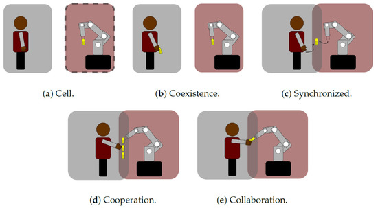
Figure 1.
Robot interaction [22].
- (a)
- No interaction (Cell): The robot remains inside a work cell.
- (b)
- Coexistence: Humans and robots do not share the workspace.
- (c)
- Synchronized: Allows sharing the workspace, but never at the same time.
- (d)
- Cooperation: The task and the workspace are shared, but humans and robots do not physically interact.
- (e)
- Collaboration: The operators and robots share the workspace and exchange their forces for the same task.
Analyzing the five types of interactions, multi-robot cooperative systems have demonstrated stronger operational capabilities, more flexible system structures, and better coordination capabilities, operability, and work efficiency [24,25,26].
An advantage of multi-robot cooperation resides in the possibility of operating independently or together [3,7,27,28,29,30,31], in either coordinated/cooperative or uncoordinated tasks [32]. In the first type of operation, the robots follow one another, and the robots and objects interact during the task. In the second type of operation, the movements are independent and synchronized [3,32,33,34]. Therefore, multi-robot cooperation has become an important challenge for robot control [24,25,26], because their movements must be synchronized to avoid collisions. Thus, to accomplish this requirement, the system control could be divided into a supervisor–agent control or a hybrid force/position [29,35,36].
The most popular multi-robot cooperation applications employ a supervisor–agent controller to avoid collisions between the robots and the other objects [37]. The functioning of the supervisor–agent controller is as follows: The agent must adhere to orders sent by the supervisor. The supervisor forces the agent to adapt its trajectory and avoid interference with the master or objects [37,38] This controller has two control units. Hence, they have different domain times [37]. It is essential to coordinate time, because its delays result in non-coordinated displacement. The robot manufacturers try to resolve the coordination problem through the unification of all axes in one controller. This solution is limited to 12 degrees of freedom (DOF), and the robots cannot operate separately.
The second kind of control is divided into two subdomains: one for the force and the other for the position [27,29]. This control is used when the kinematics are in a close loop, such as when both robots take an object. In this case, the position and speed of each robot must be relayed at the same time. The complexity of this advanced control requires a high level of computation [30,39,40,41]. The traditional control has limitations when it integrates new algorithms and/or new sensors, due to their computational capacities. Thus, this control is embedded in an external element such as an industrial PC, a PLC, or a simple PC. The solutions suggested by some authors are based on communication networks using TCP/IP sockets [34,38,42]. Other authors promote the use of ROS using additional PCs [5,7,11,35,43,44]. Another possibility is the use of a PLC system with industrial protocols such as Profinet or Profibus [45] to send the information to both robots at the same time.
Dual-robot coordination generally works with an external control system, focusing on a centralized decision-making approach with fixed and rigid control logic. Hence, the flexibility and the reconfigurable response are reduced [7]. In this kind of control, the state machine sends motion commands to robots when the task is finished for one of them. The state machine sends the next positional information only when both robots are finished with their movement. Then, the external control with the state machine ensures adequate coordination.
The digital twin (DT) concept has gained a lot of attention given the advantages that it may offer in terms of providing perception and cognition abilities towards more autonomous and intelligent robotic systems [46,47]. In current manufacturing cases, the machines have their own control and they do not interact between themselves. DT suggests centralizing all control machines in one, and it manages all production parameters. Digital representation and simulation of the production environment and process have arisen as a method of partially addressing production systems’ performance improvement [48]. Highly flexible, reconfigurable, and modular solutions are required in modern manufacturing systems.
The goal of this research project was to create a flexible, reconfigurable, cooperative, and collaborative robotic system that could handle and clamp huge, heavy, and complex pieces weighing up to 250 kg, improving hard labor jobs while preventing operator injuries.
The software developed in this paper enables controller coordination of the movements of two cooperative AURA robots [49].
This software integrates the following:
- A digital twin (DT) that defines the reference part with an HMI, allowing monitoring and visualization of the robots’ movements;
- A high-level control with a machine states module, a path generator module that calculates the coordination trajectories, a robot coordinated motion module, and a robot independent motion module.
The uniqueness of the suggested approach is based on the use of an external controller to control multiple robots, even using different brands. Moreover, all of the signals are centralized.
The work described in this paper demonstrates the coordination of two AURA robots during bimanual operation in three different cases—without load, with a dummy part, and with a real large aeronautic part—from the grasping position to the ungrasping position. The format of this research article is as follows: Section 2 introduces the problem description and the hardware architecture. The methods used to construct the application are described in Section 3. Section 4 contains a description of the tests that were carried out and their outcomes. Finally, Section 5, Section 6 and Section 7 present the discussion of the work completed, the conclusions, and the work to be done in the future.
2. Problem Description
One or more robots are typically used in a typical application to perform different processes or operations on the piece while updating the fixture tooling and positioning of the parts.
The aeronautical components in this study must be moved with the least amounts of torsion, plane strain, and shear stress. A 360° turn movement is necessary because the displacement must be given room to seal two faces of the aeronautical part. At present, the operators manually clamp the component in a fixture mechanism. Once it is clamped, another operator uses an anthropomorphic robot to apply the seal.
Three alternative approaches need to be taken to solve the issue:
- Handling bulky items to substitute the fixture tooling;
- Various component dimensions;
- Operators fixing parts.
The coordinate system makes use of two anthropomorphic robots to address the problem of handling huge parts to replace the fixture tooling. Each robot uses a flexible and customizable tool to explore a subject with various part dimensions. Finally, the collaborative cooperation system uses hand-guiding controlled by an operator to facilitate the clamp portion and analyze the problem of the parts’ fixation.
2.1. System Description
In this system, the operators and robots need to share the workspace and exchange their forces during the hand-guiding activation. This operation is a collaborative task, and to respect the directives of both ISO/TS 15066 and ISO/DIS 10218 it is necessary to use collaborative robots. Two AURA cobots were selected from the COMAU (Torino, Italy) portfolio, each with a payload of 170 kg and reach of 2800 mm [49]. These robots are considered to be collaborative due to human interactions with their sensitive skin. Moreover, they fulfill the specification of being able to hold large and heavy parts. The COMAU’s hand-guiding option is mounted on the tooling and integrated into the COMAU’s control. This allows the operator to place the clamping device in front of the piece easily.
The two cobots handle and place the part in an exact position while the industrial robot (KUKA) performs the sealing process. Once the sealing process is finished, the two cobots must turn the part to then be able to seal the other side.
In the current control systems, the coordination robots with independent controllers need a good level of synchronization to achieve a good level of operation in the handling process. Even though the two AURA cobots possess the same mechanical and dynamic characteristics, they start the trajectory at different times and pick out the best-fit motion to arrive at the same pose. This control may lead to damage to the workpiece and/or robot.
To solve the constraints of the multi-robot handling coordination, a coordinated motion trajectory must be planned to achieve the desired position during transportation to reach the sealing position whilst simultaneously moving all of the robots.
For planning the path coordination motion, the system involves two phases:
- Path generation:
- ○
- Part path generation;
- ○
- Robot path generation.
- Synchronized motion.
The handling of the part with two robots forms a closed chain.
For the robots’ synchronized motion, the system requires a supervisor called a high-level controller (HLC). The HLC manages the information sent and received from the devices connected to it. The associated devices are two cobots for handling, an industrial robot for sealing, and a DT.
In the following subsections, the hardware architecture is described in detail.
2.2. Hardware Architecture Description
When an automation problem requires 12 DOF, robot manufacturers typically propose the use of a single controller simultaneously commanding 12 axes across both robots (six per robot). This proposition diminishes the robot’s flexibility and increases the cost, because the robots cannot work separately, and the control must be programmed for a specific task. Furthermore, the controller must increase the number of command axes.
The current controller of the COMAU robots can only manage up to 8 axes. Due to this limitation, an external HLC is needed to command both robots (as well as any additional robots). This external HLC uses an industrial PC (IPC) from Beckhoff (Verl, Germany).
The hardware architecture of the system is shown in Figure 2. The system is based on a DT, an external HLC, two AURA COMAU cobots, a KUKA robot for the sealing process, and a safety PLC.
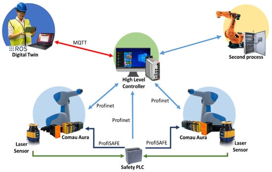
Figure 2.
Architecture of the system.
To control and monitor the operation of the system a digital twin (DT) was developed. This offers easy integration of the smart human–machine interface (HMI) using tablets or smartphones. This HMI assists the operator when the system needs to be monitored or when it needs to send commands to the HLC. The communication between DT and the HLC is established through the MQTT (Message Queueing Telemetry Transport) protocol [50].
The HLC receives the commands from the operator, calls the module generation coordination motion, sends data to each robot, ensures the coordination movement, motorizes the synchronization, and sends the actual position to the DT.
The two AURA COMAU cobots are connected to the HLC via the industrial protocol Profinet to guarantee good communication between them, to ensure a synchronized cycle, and to exchange data between the two systems to an accuracy of below 4 ms.
Even if the robots are collaborative, the part and the tools are not; therefore, an operator could be hurt by them. To ensure that the application is collaborative, extra safety hardware is needed. These lasers are connected to a safety PLC. This PLC acquires all safety signals (laser barriers, emergency stops, etc.) and sends suitable signals to the robots via the PROFISAFE network and HLC using the Profinet protocol. Once the laser barriers detect any presence inside the limited area, the COMAU AURA robots decrease their speed, and the robot from the second sealing process stops. This functionality reduces risks in case of any collisions with the parts or operators. In addition, it enables manual operations to be performed under safe conditions, without the need for fences [51].
3. Software Development
The different software developments are described in this section. The DT application is first defined in detail, and the HLC programming is then described, including the communication between the DT and HLC, the developed state machine, and some low-level functions for coordinating the robots’ operation.
3.1. Digital Twin of the System
A modular digital twin is proposed in this work to enable the flexible control of the robotic cell, to more easily command the operations, and to remotely monitor the execution. This approach also has the advantages of fast integration with a production system and the ability to be independent of the hardware used. The objective of the proposed approach is to overcome existing constraints in the orchestration of process execution as well as online reconfiguration of smart production systems through the application of the following:
- Production, execution, simulation, and validation of the human–robot (HR) collaborative production system; accurate simulation of robot behavior based on generated sensor data to enable the correct evaluation of the system.
- Virtual representation by integrating sensor data, resource information, and CAD models. The information is updated through a network of services of all resources and sensors, resulting in a synthesis of perceptual data, which are used to compile the DT.
- Simplified control of robotic agents and sharing of sensor data through ROS-based services [52]. This facilitates the distribution of acquired data and tasks to all relevant agents, such as robots and workers/operators.
The identified elements from the real world represented in the DT are (a) human workers, (b) collaborative robots, (c) the product and its elements, and (d) sensors. The proposed DT aims to provide an abstract interface for all of these elements to achieve easy integration without suffering compatibility issues due to complex hardware or software requirements.
The DT that acts as the execution controller of the HR collaborative assembly proposed in this paper was formed from a set of software components. The overall architecture is presented in Figure 3. The major components of the DT are enclosed in the digital twin area of the diagram. The diagram also describes the external components that require a connection with the DT to establish an HR collaborative production system.
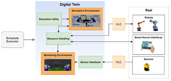
Figure 3.
Digital twin architecture diagram.
The resource-handling component is the software responsible for regulating the production system’s related resources (e.g., workers, robots). This component offers a centralized interface for all agents to receive instructions and communicate their status. As seen in Figure 4, a state machine describes the status of each agent. On this basis, the schedule executor can supervise the manufacturing process. Initially, the agents are in the pending state, waiting for a new action to be executed. The parameters of the received actions are validated before execution. This technique is unique to each agent and is adjusted according to the agent’s payload, equipped tool, and reach envelope, among other factors. After the action is accepted, the execution procedure begins; the agent’s state changes to active, and the agent continuously provides input about the process to the system. In the event of an error, the agent aborts the current activities, and a reset procedure is implemented to prepare the next action. The agent enters the succeeded state upon successful execution of the action and, when the handling interface receives the result, the agent is ready to receive another action.
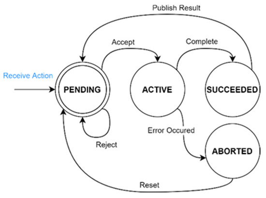
Figure 4.
Resource handling state machine.
For human workers, the action is routed through the DT’s smart human interfaces. These interfaces notify the operator of his/her action, provide assistance, and await the operator’s input on the action’s completion. On the other hand, robotic agents have distinct monitoring and control requirements. The high-level controller is the component responsible for receiving action goals and updating the robotic agent’s state.
3.2. High-Level Controller (HLC)
The high-level controller centralizes the control of the handling operation of both cobots, managing the collaborative actuation with the industrial robot for the sealing process, along with the DT. It manages the information sent and received from the connected devices.
As detailed, the brain of the application is the high-level controller. In Figure 5, the block diagram of the HLC is detailed.
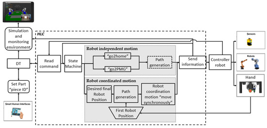
Figure 5.
Block diagram of the HLC.
The HLC receives inputs from the operator through the DT as an emergency stop, a confirmation that the part is being grasped, and the identification of the part (ID piece). The HLC receives the commands from the operator (read command), decodes the data, and sends motion commands (depending on the state machine). Afterwards, it calculates the trajectory for each robot, taking into account that their motion could be independent or coordinated. Finally, it sends the actual state data to be visualized as well as the position and speed for each robot (send information) back to the DT. In the following sections, each task is described.
3.2.1. Read Command
The goal of this function is to connect the DT with the robot controller via the HLC, read the information of both systems, and translate all of the data in a common language.
The robot controller transfers the actual position of the robot, the activation of hand-guidance, and the interruption of the laser sensor barrier to the HLC, including the part used from a select catalogue, the confirmation of a part being grasped by the operator, and the motion commands.
Once the part is attached and acknowledged, an operator must send move commands to the HLC to start the application. These instructions are transmitted through MQTT messages from the tablet to the DT.
3.2.2. State Machine
When the message from the operator is received and interpreted, the system actuates based on the state machine shown in Figure 6.
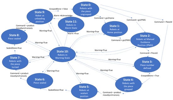
Figure 6.
Bloc diagram of the state machine.
This state machine enables the HLC to centralize the information of the robot and the DT, to exercise control of the system, and to be able to take decisions according to the current status as well as the status of several variables.
Each state commands different functions, such as “go2home”, “go2PMG”, “PieceId”, or “Product move synchronously”.
3.2.3. Robot Independent Motion
This function is used to move the robots separately. In this sense, the visible options to program the functions are as follows:
- Programming trajectory through robot language (PDL).
- Programming trajectory through the function path generation.
In this paper, the functions “go2home”, “go2PMG”, and “PieceId” are proposed to work separately. Each of these functions programs its trajectory with the function path generation.
The command “go2home” sends both robots to their security position. The command “go2PMG” moves the robot to a theoretical approach position in which the operator can grasp the part. In both cases, the robots have different speeds and trajectories
Robot Coordinated Motion
The goal of this function is to guarantee the synchronized motion of the robots. This function is the key to the application and is shown using a block diagram in Figure 7.
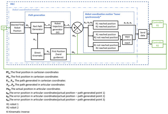
Figure 7.
Diagram of robot coordinated motion.
In order to ensure that the robots’ displacement reduces stress on the manipulated elements, their coordinated motion requires a common reference that can be used to construct the trajectories and movements, as described in the next subsection.
The command “PieceId” defines the part that is used during the task. This command looks for the final points of the trajectories for the part that can be selected from a predefined catalogue.
Each synchronized movement’s first step is actuated just once after the command “PieceId” and the first position (i.e., hand-guidance) have been established. The trajectory that the piece will follow is then determined using those checking points (i.e., part path generator). Next, a robot trajectory generator is put into action. This layer generates the array of joint configurations that each robot must adopt in order for the part’s center to follow the intended travel trajectory. Thirdly, each robot executes the estimated route, necessitating cooperation between the two robots to keep a constant distance between them. In the subsections that follow, each layer is described in further detail.
Robot Referencing
The coordination motion requires a single reference that enables the robots to move to the same point regardless of their base reference. Therefore, it is vital to define an accurate common reference (i.e., World) to avoid any damage to the part while it is handled by both robots. However, due to the characteristics of the parts to be handled, the distance between the two robots is larger than the reach of each individual robot. Hence, the definition of a common World reference point must be defined outside of the robot workspace. To do this, an auxiliary reference for each robot (Oa1, Oa2) is calculated inside their own working space. Then, each auxiliary reference is transformed into a common reference, as shown in Figure 8.
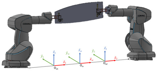
Figure 8.
A common reference defined by projecting each auxiliary reference.
To simplify the procedure, a longitudinal line that connects both robots is drawn on the floor, as shown in Figure 9. This line defines the x-axis of all of the references (i.e., Oa1, Oa2, Ow). In this way, the transformation of the auxiliary references into the common reference is easier, since it must be translated in just one axis.
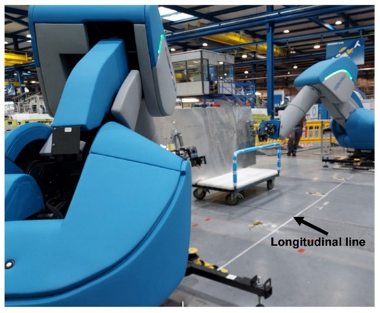
Figure 9.
A longitudinal line that connects both robots.
Once the line has been defined, an auxiliary reference is obtained by using a threaded rod and defining a point on the floor whilst ensuring that the robot is completely perpendicular to the floor.
Once the auxiliary reference systems are defined, they must be changed to a common point. In this specific case, it was decided to place the common reference system in the center between both robots (note: the center of both robots does not have to be the center between both origins).
Euler angles in AURA robots use the ZYZ convention, so the roto-translation matrix between the base of each of the robots and the reference systems can then be defined. For the convention case, ZYZ would be the equation defined in Equation (1):
- where
Since the projection of the common reference frame onto the auxiliary reference frame is achieved simply via a pure translation on the “x-axis”, the roto-translation matrix between the robot base and the common reference frame is a pure translation in the “x-axis” of the auxiliary system y, which is defined by Equation (2):
- where dx is the position of the common reference frame on the “x-axis” of the auxiliary reference frame.
The obtained roto-translation matrix defines the position and orientation of the common reference system, “World”, in terms of the coordinates of the robot’s base. However, COMAU defines the World as the distance and orientation of the robot in the World coordinates. Thus, the previously obtained inverse matrix needs to be calculated, as defined by Equation (3):
Then, the distances (, , ) and the Euler angles (, and ) from the homogeneous transformation matrix are obtained. Obtaining the distances is straightforward, since the homogeneous transformation matrix is defined as shown in Equation (4), so the distances (, , ) correspond to the last column of the matrix.
However, determining the angle is not trivial. In the first place, these data cannot be obtained directly from the matrix, but must be calculated from the data of the matrix. Secondly, the angles obtained are not unique, unlike the homogeneous transformation matrix. Hence, there is more than one set of Euler angles that result in the same matrix. Therefore, despite starting from a set of different angles, the resulting homogeneous transformation matrix will be the same, as long as the set of Euler angles is equivalent.
In addition, there is an extra limitation interposed by COMAU. When the angles are introduced, the second Euler angle, , must be positive. During the preliminary tests, several calculations of angles were carried out by more than one method until a solution satisfied the former restriction. In this sense, the following four options [53] were tested until valid Euler angles were achieved whilst fulfilling the limitation that the second Euler angle was positive. In this case study, Option 4 was identified as the most valid method. When the world referencing was calculated, the procedures to solve the system equation were tested.
Option 1:
Option 2:
Option 3:
Option 4:
Path Generation
This function enables the calculation of the feasible movements that the robots must follow according to their physical restrictions, speed limitations, collisions, working area, etc. This function must generate the trajectory for both robots and must guarantee that it is performed whilst minimizing the external stresses. This function is divided into two parts: a part path generator and a robot trajectory generator.
- Part Path Generator (PPG)
This module generates the path (in Cartesian space) that moves the handling part based on the given points. The obtained path provides a series of points in each of the robot’s frames that enable the part to be transported.
Initially, the library reads the part position on the World frame and checks the points that the part trajectory is commanded to go through. From these data, the movement of each grasping point is calculated to ensure the safe movement of the large part. The path generator consists of a C++ library based on the Eigen library to perform geometric and linear algebra operations. The implemented C++ library allows the following:
- The definition of grasping points for both robots on the part frame (i.e., transformation between the part origin and grasping points) and the tools of each robot (i.e., transformation between the flange and tool).
- The trajectory parametrization of the grasping points, followed by the part’s movement in the common World frame.
- The implementation of functions to change the frames of the calculated trajectories from the World (i.e., the common frame between robots) to each robot’s base.
The part path generator module aims to generate Cartesian trajectories for the two grasping points to achieve the intended part path. The module implements a linear interpolator to generate high-resolution discrete trajectories, enabling better control of the manipulator behavior. Generated paths are sent to the robot trajectory generator module for further kinematic calculations, as explained in the next section.
- 2.
- Robot Trajectory generator (RTG)
The robot trajectory generator module performs a kinematic calculation, enabling the description of the motion of bodies. Therefore, no external forces (e.g., loads, Coriolis forces, centers of mass, inertia moments) are considered.
The RTG module enables the analysis, calculation, and verification of the movements that each robot must follow, according to the previously generated path. The goal of this module is the generation of the joint poses for all points of the path calculated by the PPG, considering the axis space range and maximum speed.
Kinematic analysis of the robots is performed with the Denavit–Hartenberg modified (DHM) parameters [54]. The robot trajectory that each robot must follow is then calculated, taking these data into account as well as using the Robotics Library (RL) [55].
In the part path generator module, the information acquired is in Cartesian coordinates as defined on the World frame. However, these (desired) positions must be decoded to articulate the position of each robot. Therefore, the inverse kinematics method is employed to obtain the articular coordinates. Through the use of the developed C++ library and the RL, the RTG module can perform the following functions:
- Calculate direct and inverse kinematics;
- Determine the working range of each axis;
- Calculate the maximum speed of each axis defined by the robot manufacturer;
- Verify that the robots can reach every pose along the trajectory and robot singularities;
- Show motion simulation in 3D.
If any kind of error is detected during the trajectory generation (e.g., trajectory outside of the robot’s working area, the articular position exceeding the robot’s physical limitations, consigned speed too high, etc.), the operator is notified of the error through an MQTT message sent to the digital twin. In this case, new points can be defined and sent back, and a new trajectory can be calculated. If no errors have been detected, the trajectory is downloaded to the TwinCAT3 program to be used in the trajectory executor layer.
Robot Coordination Motion “Move Synchronously”
This module executes the trajectories in joint space, ensuring the synchronization of movements. In order to use this function, some mechanisms are needed to execute the robot movements in real time, ensuring the robot coordination.
This feature, developed in TwinCAT3, commands the COMAU cobots to exchange information using the Profinet network. Additionally, a program written in PDL2 (COMAU robots’ programming language) is used to obtain the actual positional information and to move the robot according to the trajectory.
When the robot coordination motion “move synchronously” function is launched, several points are given, through which the center of the part must pass. These include the points at which the center of the part starts, the point at which the center of the part must finish, and any other significant points in between, which are given as arguments of the functions (Figure 10).
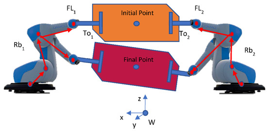
Figure 10.
Reference World and center part.
The coordination is obtained by sending the first three points of each trajectory to their respective robot. Once a robot reaches one of the points, the robot notifies the HLC of the new position. In the case that both robots have reached the point, the next three points are sent. If not, the robot that has reached the position remains stopped until the other robot reaches its corresponding position.
3.2.4. Send Data Information
Finally, the actual state of the system is sent to the digital twin based on MQTT messages but using other topics.
4. Test and Results
In this study, the application’s performance was evaluated using three different use cases, which are described below. The system must support two flexible and configurable tools used for clamping a large part on both sides. Hence, both robots must handle a total weight of about 80 kg. This application is highly interesting in the aeronautical sector, as there is a very common need to handle large and heavy parts before performing subsequent processes such as sealing, painting, or sanding.
Three different tests were carried out for this paper:
- Coordination motion “without” a part.
- Coordination motion with a “dummy” part. This component had actual aeronautic part dimensions (2450 × 1125 mm). However, it was made of aluminum and weighs 21 kg.
- Coordination motion with a real “aeronautic” part. The dimensions of this part were 2800 × 900 mm. It weighed about 19 kg and was made of composites.
Algorithm 1 represents the completed sequence generated by the program.
| Algorithm 1. Handling task | ||
| 1 | : | function Handling task |
| 2 | : | if (finish all part = true) then |
| 3 | : | Home Position |
| 4 | : | return finish all part = true |
| 5 | : | else |
| 6 | : | while finish all part = false do |
| 7 | : | if ((robot1 = Home Position) or (robot2 = Home Position)) then |
| 8 | : | Approach Position |
| 9 | : | if ((robot1 = APos) and (robot2 = APos)) then |
| 10 | : | return APos = true |
| 11 | : | else |
| 12 | : | return APos = false |
| 13 | : | end if |
| 14 | : | end if |
| 15 | : | if (APos = true) then |
| 16 | : | Grasping part by operator |
| 17 | : | return Grasping = true |
| 18 | : | else |
| 19 | : | ungrasping part by operator |
| 20 | : | return Grasping = false |
| 21 | : | if (stop task = true) then |
| 22 | : | return finish all part = true |
| 23 | : | else |
| 24 | : | return finish all part = false |
| 25 | : | end if |
| 26 | : | end if |
| 27 | : | if (Grasping = true) then |
| 28 | : | coordinated trajectory to sealing position |
| 29 | : | if (sealing process = false) then |
| 30 | : | keep position |
| 31 | : | else |
| 32 | : | if (sealing one side = true) then |
| 33 | : | coordinated trajectory to turn the part |
| 34 | : | coordinated trajectory to sealing position |
| 35 | : | else |
| 36 | : | Approach Position |
| 37 | : | end if |
| 38 | : | end if |
| 39 | : | end if |
| 40 | : | end while |
| 41 | : | end if |
4.1. Results of Module Path Generation
The trajectory planning for motion coordination in the handled part was divided into three different paths that were executed sequentially:
In the first, a pure vertical translation movement along the z-axis was achieved, after which the trajectory displacement was moved along the y-axis until the part was in front of the second process robot.
The second path consisted of three movements: a horizontal backwards translation over the y-axis to avoid any collision with the second process robot, a 180° rotation over the x-axis around the center of the part, and a forward translation along the y-axis until the b-side of the part was situated in front of the second process robot.
The third path consisted of a backward movement along the y-axis until half of the distance to avoid collisions, a rotation of 180° around the x-axis over the center of the part, a forward translation along the y-axis until the initial position was reached, and then a pure vertical translation in the z-axis.
Based on this trajectory, in Section 4.2 and Section 4.3 the trajectory tracking results and the maintenance of the relative distance between grasping points are detailed, respectively.
In Figure 11, the trajectories followed by the grasping points of Robot 1 and Robot 2 for the dummy part are shown.
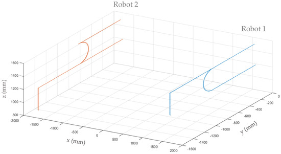
Figure 11.
The trajectory paths followed by the grasping points for the dummy part.
To achieve the trajectories shown in Figure 11, the desired trajectories were discretized into 8 mm steps for translation movements and 1° steps for rotations. Then, the obtained Cartesian trajectory of the part was been transformed into the articular trajectory for each robot with the RTG. Afterwards, the articulated points of the trajectory were sent as commands to each robot, ensuring coordinated movement.
4.2. Results of the Robot Coordination Motion Module “Move Synchronously”
Figure 12 shows the steps followed by the dummy part according to Algorithm 1 and based on the calculated path trajectory. Hence, after placing the part in a specific position inside the work cell, the dummy part was clamped manually by an operator (Figure 12, Step 1). Note that each clamping point was situated at a different height. This is not a handicap, since the developed algorithm maintains the geometric distance along the whole trajectory. In Step 2, the information of the coordinated trajectory calculated by the module path generation was read and executed in both robots to place the dummy part in front of the second process. The dummy part was kept in the same position whilst the second process robot (i.e., sealing) was working on the a-side of the part (Step 3). After the second process was finished, Step 4 was executed to change the orientation of the dummy part to follow the process operation on the other side (Step 5) of the dummy part. Once again, the dummy part was maintained in position until the other robot finished its task. Finally, in Step 6, the dummy part was moved to the initial position and returned to the same orientation that it had at the beginning. The operator could then carry out the ungrasping of the part.
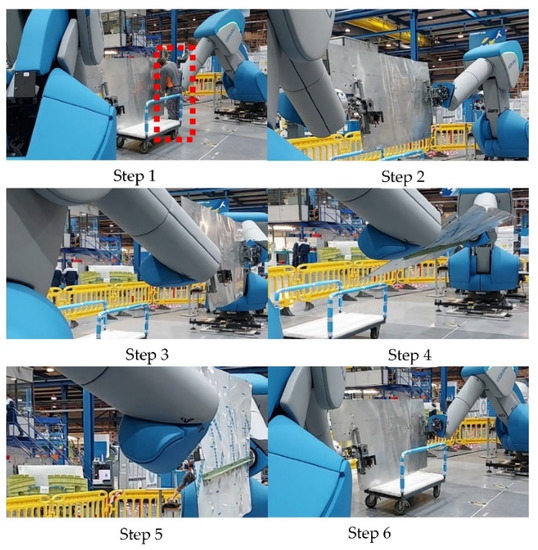
Figure 12.
Step-by-step handling process.
To validate the coordination motion, the trajectory calculated by the robot trajectory generator (RTG) must be compared with the real articular position of each robot. The shape of the target trajectory (i.e., desired joint position) is due to the coordination algorithm. In order to coordinate the movement, a new position at each joint of each robot is sent every 4 ms. However, if one of the robots does not reach the desired position, the other one has to wait until the position is reached, as detailed in [56].
Figure 13 illustrates the real (current) trajectory on axis 6 compared with the path generated by the RTG (desired P1) for each robot (Robot 1, Figure 13a; Robot 2, Figure 13c) whilst they are handling a dummy part. This information corresponds to the real joint trajectory carried out by each robot for the Cartesian trajectory shown in Figure 11.
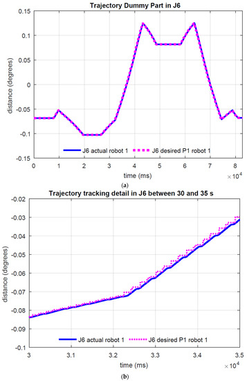
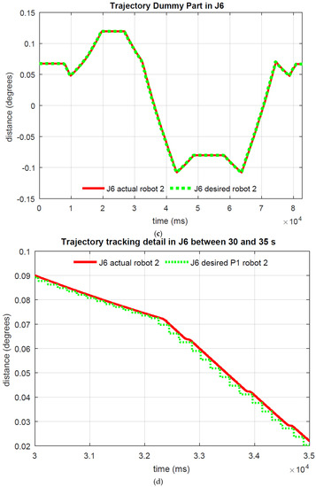
Figure 13.
(a) Joint 6 trajectory (current and desired) for Robot 1. (b) zoom under 30 s and 35 s for Robot 1. (c) Joint 6 trajectory (current and desired) for Robot 2. (d) zoom under 30 s and 35 s for Robot 2.
To acknowledge that the position has reached the commanded point, so that the subsequent reference points can be sent, the difference between the required position and the current position in each joint of each robot is continuously checked, as explained in the diagram shown in Figure 7.
For each robot, Equation (5) must be fulfilled for (the desired point) and (the current position of each joint). Therefore, the algorithm performs the following calculation in every scan cycle:
For the sake of simplicity, only the Joint 6 trajectory (desired and current values) of both robots is represented in Figure 13, showing the total trajectory (Figure 13a,c) and the detailed trajectory for 30 s to 35 s (Figure 13b,d). As depicted, the joint trajectory tracking is highly accurate, with the maximum error for each joint being less than 0.35 degrees.
4.3. Distance between Grasping Points
Even if the articular positions achieve a good performance during the coordination motion, it is crucial to control the distance between the grasping points. Since the part is quite rigid, the distance between the grasping points should be maintained constant, regardless of the position of each robot. Hence, the Cartesian position of each grasping point was monitored. Based on these data, the distance between the grasping points was determined by applying Equation (6):
The distance between the grasping points along the coordination motion trajectory is shown in Figure 14. The coordination motion without the part is shown in Figure 14a. In this case, the ideal distance was 3187.18 mm, while the mean distance measured was 3187.2 mm with an error of ±0.3 mm. In Figure 14b, the coordination motion with a dummy part is shown; the ideal distance was 3014.2 mm, and the mean distance measured was 3014.256 mm with a maximum error of ±2 mm. Finally, the coordination motion for an aeronautic part is illustrated in Figure 14c; the ideal distance was 3380.6 mm and the measured distance was maintained at 3380.6 mm with a maximum error of ±4 mm.
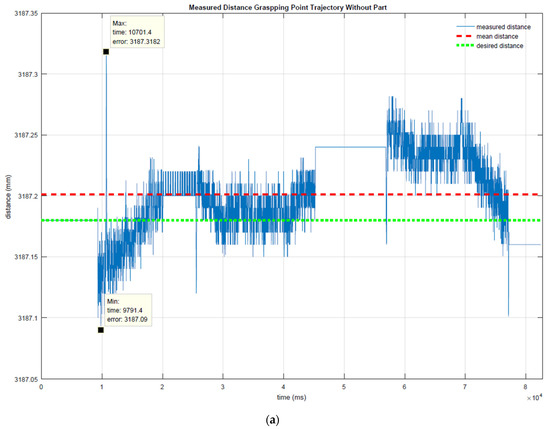
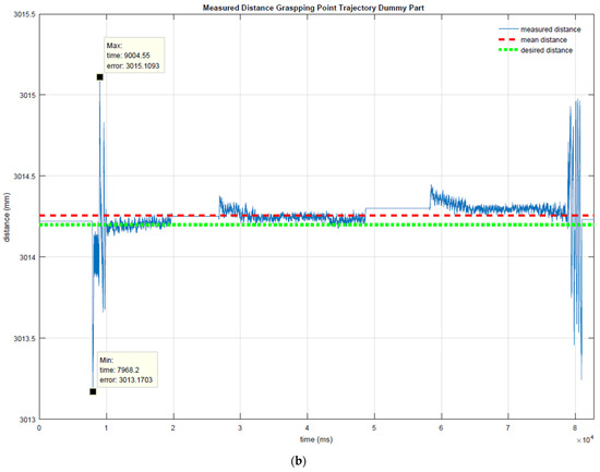
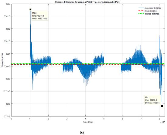
Figure 14.
Measured distance between the grasping points during the trajectory (a) without trajectory (b) with dummy part and (c) with aeronautic part.
The maximum errors occurred during the initial and final movements, due to acceleration and deceleration moments.
The representative error parameters are shown in Table 1. The mean value represents the arithmetic mean value of the calculated distance, delta represents the distance between the maximum (Max) and the minimum (Min) distances measured, mean squared error (MSE) measures the average of the squares of the errors, and the root-mean-square deviation (RMSD) represents the square root of the second sample moment of the differences between the predicted values and observed values.

Table 1.
Main error values obtained from the distance between grasping points during the trajectory.
These data clearly show that the distance between the grasping points remains quite constant. The error obtained can be absorbed by the clearance of the grasping point itself, or even by the tool, design to absorbed errors of up to ±10 mm.
5. Discussion
Trajectory programming is more intuitive for the operator in Cartesian coordinates, because they can then measure the physical distances. However, in the robot, the Cartesian coordinates have different solutions for any given position. When two or more robots require a coordinated path, the best option is to work in articular coordinates to avoid singularity problems.
In our case, the part path generator enables the part trajectory to be defined through its geometric center, as well as the intermediate and final points that the part must follow. The center of the part is calculated based on the positions of the grasping points. The intermediates and final points are predefined in the files depending on the movement of the part. However, this definition could also be modified to achieve other trajectories.
The robot trajectory generator enables the operation in articular coordinates according to the previously described trajectory. The trajectory is divided into 8 mm steps; however, the robots’ motion is slower, because they cannot achieve their maximum speed. This discretization could be improved by considering the dynamic information. Moreover, external forces must be considered to improve the system.
The robot coordination motion module “move synchronously” achieves a good performance; however, to improve the repeatability of the robot coordination, it is necessary to be able to read more than three points, and the system’s communication must be faster. An internal program (e.g., PDL) is capable of reading more than five points when they have small changes in position. It is also limited for the robots’ external communication, where it is limited to sending and receiving information every 4 ms; however, the internal communication is much faster.
The principal requirement whilst moving the aeronautical part is to cause the minimum amount of mechanical stress (e.g., torsion, shared strain). To accomplish this requirement, it is important to supervise the distance between the grasping points and to ensure that this remains within the limits. The maximum limit in our case is 10 mm. This distance was respected for the three tests that were performed. However, to enhance the distance variation, it is imperative to also consider the robot and the tool deflection depending on the part weight and its inertial centers, so as to then generate the part path using this inertial center, rather than using only its geometric center.
6. Conclusions
In this study, different concepts were integrated to achieve all of the industrial requirements, as follows:
- When the operator clamps each robot tool to the part, the robot and operator have completed their cooperative work. When the protective zone is violated, the security systems slow down or apply the brakes. These mechanisms are in place to ensure that operator hazards are kept to a minimum and to achieve the robots’ collaborative norms.
- Reconfigurable tools are still necessary to manipulate parts with various dimensions, shapes, and large payloads.
- Based on the current state and the commands received from the digital twin, the state machine determines what has to be done. The state machine then connects the robot controllers to send the planned trajectory.
- The digital twin enables remote control and monitoring of task execution while visualizing the actual positions of the robots.
The main contribution focuses on the coordination problem for handling and moving the part, which implies the generation of a valid trajectory, the correct performance in the execution of the movements, high precision in the reference system, and control of the synchronization of the robots.
Considering that the problem to be solved consists of the manipulation of large aeronautic parts, the common reference World is beyond the reach of both robots. To keep things simple, the reference system is placed in the center of both robots.
The robots are considered as a detached system, meaning that each robot considers 6 DOF. The kinematic study of this paper is only valid for COMAU robots. However, the methodology could be extrapolated to other brands of robot. The trajectory is generated in Cartesian coordinates to assist the operator in the programming and modification of the path (i.e., function path generation, part path generator). However, the target of each robot is calculated (via the robot trajectory generator) using articular coordinates to minimize the configuration problems.
The part trajectory is divided every 8 mm to guarantee that the difference in displacement between both robots is no more than 10 mm.
The function “robot coordinated motion” enables the position sent to the robot controller to be managed. Therefore, when one of the robots does not finish the movement, the other one waits in the same position.
The controller used in this research is external and only controls the articular position. This controller must send the information and control the position every 4 ms, which represents the cycle time of the robot controller. This is achieved using the Profinet network. The advantage of using a Profinet communication network is that it enables the modulation of the time, transmitting the information in microseconds.
7. Future Work
Preliminary results must be tested with different aeronautic parts in order to improve the system’s performance. To achieve this, it is important to adjust the trajectory generation, taking into account the robot’s dynamics while also considering the trapezoidal speed profile (i.e., the acceleration and deceleration). Another point to be tackled in future works is the possibility of modifying the path granularity depending on the trajectory distance. Creation of the automatic path planning and collision modules and the development of a kinematics database to use on other brands’ robots are other points to be considered in the future.
Author Contributions
Conceptualization, S.M.D.L. and S.M.; methodology, I.D.J.G.O. and P.B.; software, I.D.J.G.O., P.B., A.I., P.A., K.L. and C.G.; validation, I.D.J.G.O. and P.B.; formal analysis, I.D.J.G.O.; investigation, I.D.J.G.O., P.B. and A.I.; resources, I.D.J.G.O.; data curation, I.D.J.G.O.; writing—original draft preparation, I.D.J.G.O. and P.B.; writing—review and editing, I.D.J.G.O., P.B. and J.C.A.-U.; supervision, J.C.A.-U., S.M.D.L. and S.M. All authors have read and agreed to the published version of the manuscript.
Funding
The work leading to this publication was funded by EIT Manufacturing under the code 21055. EIT Manufacturing is supported by the European Institute of Innovation and Technology (EIT)—a body of the European Union.
Data Availability Statement
https://eit-mfg-sofocles.eu/ (accessed on 8 November 2022).
Conflicts of Interest
The authors declare no conflict of interest.
References
- Hu, S.J.; Ko, J.; Weyand, L.; Elmaraghy, H.A.; Lien, T.K.; Koren, Y.; Bley, H.; Chryssolouris, G.; Nasr, N.; Shpitalni, M. Assembly System Design and Operations for Product Variety. CIRP Ann.-Manuf. Technol. 2011, 60, 715–733. [Google Scholar] [CrossRef]
- de Gea Fernández, J.; Mronga, D.; Günther, M.; Knobloch, T.; Wirkus, M.; Schröer, M.; Trampler, M.; Stiene, S.; Kirchner, E.; Bargsten, V.; et al. Multimodal Sensor-Based Whole-Body Control for Human–Robot Collaboration in Industrial Settings. Robot. Auton. Syst. 2017, 94, 102–119. [Google Scholar] [CrossRef]
- Tsarouchi, P.; Makris, S.; Michalos, G.; Stefos, M.; Fourtakas, K.; Kaltsoukalas, K.; Kontrovrakis, D.; Chryssolouris, G. Robotized Assembly Process Using Dual Arm Robot. Procedia CIRP 2014, 23, 47–52. [Google Scholar] [CrossRef][Green Version]
- Kousi, N.; Gkournelos, C.; Aivaliotis, S.; Giannoulis, C.; Michalos, G.; Makris, S. Digital Twin for Adaptation of Robots’ Behavior in Flexible Robotic Assembly Lines. Procedia Manuf. 2019, 28, 121–126. [Google Scholar] [CrossRef]
- Makris, S.; Michalos, G.; Eytan, A.; Chryssolouris, G. Cooperating Robots for Reconfigurable Assembly Operations: Review and Challenges. Procedia CIRP 2012, 3, 346–351. [Google Scholar] [CrossRef]
- Michalos, G.; Makris, S.; Papakostas, N.; Mourtzis, D.; Chryssolouris, G. Automotive Assembly Technologies Review: Challenges and Outlook for a Flexible and Adaptive Approach. CIRP J. Manuf. Sci. Technol. 2010, 2, 81–91. [Google Scholar] [CrossRef]
- Makris, S.; Alexopoulos, K.; Michalos, G.; Sardelis, A. An Agent-Based System for Automated Configuration and Coordination of Robotic Operations in Real Time-a Case Study on a Car Floor Welding Process. J. Manuf. Mater. Process. 2020, 4, 95. [Google Scholar] [CrossRef]
- Kousi, N.; Michalos, G.; Aivaliotis, S.; Makris, S. An Outlook on Future Assembly Systems Introducing Robotic Mobile Dual Arm Workers. Procedia CIRP 2018, 72, 33–38. [Google Scholar] [CrossRef]
- Pellegrinelli, S.; Pedrocchi, N.; Tosatti, L.M.; Fischer, A.; Tolio, T. Multi-Robot Spot-Welding Cells for Car-Body Assembly: Design and Motion Planning. Robot. Comput. Integr. Manuf. 2017, 44, 97–116. [Google Scholar] [CrossRef]
- Krüger, J.; Lien, T.K.; Verl, A. Cooperation of Human and Machines in Assembly Lines. CIRP Ann.-Manuf. Technol. 2009, 58, 628–646. [Google Scholar] [CrossRef]
- Michalos, G.; Makris, S.; Spiliotopoulos, J.; Misios, I.; Tsarouchi, P.; Chryssolouris, G. ROBO-PARTNER: Seamless Human-Robot Cooperation for Intelligent, Flexible and Safe Operations in the Assembly Factories of the Future. Procedia CIRP 2014, 23, 71–76. [Google Scholar] [CrossRef]
- Casalino, A.; Bazzi, D.; Zanchettin, A.M.; Rocco, P. Optimal Proactive Path Planning for Collaborative Robots in Industrial Contexts. Proc.-IEEE Int. Conf. Robot. Autom. 2019, 2019, 6540–6546. [Google Scholar] [CrossRef]
- Rojas, R.A.; Wehrle, E.; Vidoni, R. A Multicriteria Motion Planning Approach for Combining Smoothness and Speed in Collaborative Assembly Systems. Appl. Sci. 2020, 10, 5086. [Google Scholar] [CrossRef]
- Lotsaris, K.; Gkournelos, C.; Fousekis, N.; Kousi, N.; Makris, S. AR Based Robot Programming Using Teaching by Demonstration Techniques. Procedia CIRP 2020, 97, 459–463. [Google Scholar] [CrossRef]
- Hentout, A.; Aouache, M.; Maoudj, A.; Akli, I. Human–Robot Interaction in Industrial Collaborative Robotics: A Literature Review of the Decade 2008–2017. Adv. Robot. 2019, 33, 764–799. [Google Scholar] [CrossRef]
- Michalos, G.; Spiliotopoulos, J.; Makris, S.; Chryssolouris, G. A Method for Planning Human Robot Shared Tasks. CIRP J. Manuf. Sci. Technol. 2018, 22, 76–90. [Google Scholar] [CrossRef]
- Liu, C.; Tomizuka, M. Robot Safe Interaction System for Intelligent Industrial Co-Robots. arXiv 2018, arXiv:1808.03983. [Google Scholar]
- Dzedzickis, A.; Subačiūtė-žemaitienė, J.; Šutinys, E.; Samukaitė-Bubnienė, U.; Bučinskas, V. Advanced Applications of Industrial Robotics: New Trends and Possibilities. Appl. Sci. 2022, 12, 135. [Google Scholar] [CrossRef]
- Tokody, D.; Ady, L.; Hudasi, L.F.; Varga, P.J.; Hell, P. Collaborative Robotics Research: Subiko Project. Procedia Manuf. 2020, 46, 467–474. [Google Scholar] [CrossRef]
- Dimitropoulos, N.; Togias, T.; Zacharaki, N.; Michalos, G.; Makris, S. Seamless Human–Robot Collaborative Assembly Using Artificial Intelligence and Wearable Devices. Appl. Sci. 2021, 11, 5699. [Google Scholar] [CrossRef]
- Saldaña, M.; González Pérez, J.; Khalid, A.; Gutierrez-Llorente, J.M.; Herrero, S. Risks Management and Cobots. Identifying Critical Variables. Safety 2019, 10218, 1834–1841. [Google Scholar]
- Bauer, W.; Bender, M.; Braun, M.; Rally, P.; Scholtz, O. Lightweight Robots in Manual Assembly—Best to Start Simply! In Examining Companies’ Initial Experiences with Lightweight Robots; Raum und Bau IRB: Stuttgart, Germany, 2016. [Google Scholar]
- Olivares-Alarcos, A.; Foix, S.; Alenyà, G. On Inferring Intentions in Shared Tasks for Industrial Collaborative Robots. Electronics 2019, 8, 1306. [Google Scholar] [CrossRef]
- Gan, Y.; Duan, J.; Chen, M.; Dai, X. Multi-Robot Trajectory Planning and Position/Force Coordination Control in Complex Welding Tasks. Appl. Sci. 2019, 9, 924. [Google Scholar] [CrossRef]
- He, Z.; Yuan, F.; Chen, D.; Wang, M. Dynamic Obstacle Avoidance Planning for Manipulators of Home. In Proceedings of the 2019 IEEE International Conference on Robotics and Biomimetics (ROBIO), Dali, China, 6–8 December 2019; pp. 2737–2742. [Google Scholar]
- Zhang, H.; Zhu, Y.; Liu, X.; Xu, X. Analysis of Obstacle Avoidance Strategy for Dual-Arm Robot Based on Speed Field with Improved Artificial Potential Field Algorithm. Electronics 2021, 10, 1850. [Google Scholar] [CrossRef]
- Almeida, D.; Karayiannidis, Y. Folding Assembly by Means of Dual-Arm Robotic Manipulation. Proc.-IEEE Int. Conf. Robot. Autom. 2016, 2016, 3987–3993. [Google Scholar] [CrossRef]
- Wang, J.; Xu, J. Kinematic Modeling and Simulation of Dual-Arm Robot. J. Robot. Netw. Artif. Life 2021, 8, 56–59. [Google Scholar] [CrossRef]
- Liu, X.; Xu, X.; Zhu, Z.; Jiang, Y. Dual-Arm Coordinated Control Strategy Based on Modified Sliding Mode Impedance Controller. Sensors 2021, 21, 4653. [Google Scholar] [CrossRef]
- Papakostas, N.; Alexopoulos, K.; Kopanakis, A. Integrating Digital Manufacturing and Simulation Tools in the Assembly Design Process: A Cooperating Robots Cell Case. CIRP J. Manuf. Sci. Technol. 2011, 4, 96–100. [Google Scholar] [CrossRef]
- Xiong, J.; Fu, Z.; Chen, H.; Pan, J.; Gao, X.; Chen, X. Simulation and Trajectory Generation of Dual-Robot Collaborative Welding for Intersecting Pipes Simulation and Trajectory Generation of Dual-Robot Collaborative Welding for Intersecting Pipes. Int. J. Adv. Manuf. Technol. 2020, 111, 2231–2241. [Google Scholar] [CrossRef]
- Surdilovic, D.; Yakut, Y.; Nguyen, T.M.; Pham, X.B.; Vick, A.; Martin Martin, R. Compliance Control with Dual-Arm Humanoid Robots: Design, Planning and Programming. In Proceedings of the 2010 10th IEEE-RAS International Conference on Humanoid Robots, Nashville, TN, USA, 6–8 December 2010; pp. 275–281. [Google Scholar] [CrossRef]
- Thomasson, O.; Battarra, M.; Erdoğan, G.; Laporte, G. Scheduling Twin Robots in a Palletising Problem. Int. J. Prod. Res. 2018, 56, 518–542. [Google Scholar] [CrossRef]
- Lippiello, V.; Villani, L.; Siciliano, B. An Open Architecture for Sensory Feedback Control of a Dual-Arm Industrial Robotic Cell. Ind. Rob. 2007, 34, 46–53. [Google Scholar] [CrossRef]
- Liu, L.; Liu, Q.; Song, Y.; Pang, B.; Yuan, X.; Xu, Q. A Collaborative Control Method of Dual-Arm Robots Based on Deep 779 Reinforcement Learning. Appl. Sci. 2021, 11, 1816. [Google Scholar] [CrossRef]
- Zhang, T.; Du, Q.; Yang, G.; Chen, C.; Wang, C.; Fang, Z. A Review of Compliant Control for Collaborative Robots. In Proceedings of the 2021 IEEE 16th Conference on Industrial Electronics and Applications (ICIEA), Chengdu, China, 1–4 August 2021; pp. 1103–1108. [Google Scholar]
- Curkovic, P.; Dubic, K.; Jerbic, B.; Stipancic, T. Simultaneous Coordination of Two Robots with Overlapping Workspaces. In Proceedings of the 23rd International DAAAM Symposium “Intelligent Manufacturing & Automation”, Zadar, Croatia, 24–27 October 2012; Volume 1, pp. 549–552. [Google Scholar]
- Curkovic, P.; Jerbic, B.; Stipancic, T. Coordination of Robots with Overlapping Workspaces Based on Motion Co-Evolution. Int. J. Simul. Model. 2013, 12, 27–38. [Google Scholar] [CrossRef]
- Tarbouriech, S. Dual-Arm Control Strategy in Industrial Environments. Ph.D. Thesis, Université Montpellier, Montpellier, France, 2020. [Google Scholar]
- Tringali, A.; Cocuzza, S. Finite-Horizon Kinetic Energy Optimization of a Redundant Space Manipulator. Appl. Sci. 2021, 11, 2346. [Google Scholar] [CrossRef]
- Tringali, A.; Cocuzza, S. Globally Optimal Inverse Kinematics Method for a Redundant Robot Manipulator with Linear and Nonlinear Constraints. Robotics 2020, 9, 61. [Google Scholar] [CrossRef]
- Tsarouchi, P.; Athanasatos, A.; Makris, S.; Chatzigeorgiou, X.; Chryssolouris, G. High Level Robot Programming Using Body and Hand Gestures. Procedia CIRP 2016, 55, 1–5. [Google Scholar] [CrossRef]
- Montaño, A.; Suárez, R. Coordination of Several Robots Based on Temporal Synchronization. Robot. Comput. Integr. Manuf. 2016, 42, 73–85. [Google Scholar] [CrossRef]
- Tsarouchi, P.; Makris, S.; Michalos, G.; Matthaiakis, A.S.; Chatzigeorgiou, X.; Athanasatos, A.; Stefos, M.; Aivaliotis, P.; Chryssolouris, G. ROS Based Coordination of Human Robot Cooperative Assembly Tasks—An Industrial Case Study. Procedia CIRP 2015, 37, 254–259. [Google Scholar] [CrossRef]
- Tsui, H.H.; Griffiths, C.; Sadaat, M.; Sadak, F.; Hajiyavand, A.M. A Methodology for Developing Real-Time Interface Protocol for Industrial Robots Using LabVIEW. In Proceedings of the 2020 2nd International Conference on Electrical, Control and Instrumentation Engineering (ICECIE), Lumpur, Malaysia, 28 November 2020. [Google Scholar] [CrossRef]
- Chryssolouris, G.; Mavrikios, D.; Papakostas, N.; Mourtzis, D.; Michalos, G.; Georgoulias, K. Digital Manufacturing: History, Perspectives, and Outlook. Proc. Inst. Mech. Eng. Part B J. Eng. Manuf. 2009, 223, 451–462. [Google Scholar] [CrossRef]
- Makris, S.; Michalos, G.; Chryssolouris, G. Virtual Commissioning of an Assembly Cell with Cooperating Robots. Adv. Decis. Sci. 2012, 2012, 428060. [Google Scholar] [CrossRef]
- Kritzinger, W.; Karner, M.; Traar, G.; Henjes, J.; Sihn, W. Digital Twin in Manufacturing: A Categorical Literature Review and Classification. IFAC 2018, 51, 1016–1022. [Google Scholar] [CrossRef]
- COMAU Comau Aura Automation|Collaborative Robot. Available online: https://www.comau.com/en/competencies/robotics-automation/collaborative-robotics/aura-collaborative-robot/ (accessed on 28 February 2022).
- Organization for the Advancement of Structured Information Standards MQTT: The Standard for IoT Messaging. Available online: https://mqtt.org/ (accessed on 5 September 2021).
- COMAU AURA-COlaborative Robots. Available online: https://www.comau.com/en/media/news/2017/05/aura (accessed on 19 June 2021).
- Quigley, M.; Conley, K.; Gerkey, B.; Faust, J.; Foote, T.; Leibs, J.; Wheeler, R.; Ng, A. ROS: An Open-Source Robot Operating System. In Proceedings of the ICRA Workshop on Open Source Software, Matsuoka, Japan, 12 May 2009; Volume 3. [Google Scholar]
- Henderson, D.M. Space Shuttle Engineering and Operations Support; McDonnell-Douglas Technical Services Co., Inc.: Houston, TX, USA, 1977. [Google Scholar]
- Gonzalez-Ojeda, I. Intégration de Modèles Numériques Réduits dans le Pilotage Robots Possédant des Flexibilités dans la Dépose de Fibres. Ph.D. Thesis, Université de Nantes, Nantes, France, 2018. [Google Scholar]
- Rickert, M.; Gaschler, A. Robotics Library: An Object-Oriented Approach to Robot Applications. In Proceedings of the IEEE/RSJ International Conference on Intelligent Robots and Systems (IROS), Vancouver, BC, Canada, 24–28 September 2017; pp. 733–740. [Google Scholar]
- Bengoa, P.; González-Ojeda, I.D.J.; Ibarguren, A.; Goenaga, B.; Martínez-De-Lahidalga, S.; Gkournelos, C.; Lotsaris, K.; Angelakis, P.; Makris, S.; Antolín-Urbaneja, J.C. Coordination of Two Robots for Manipulating Heavy and Large Payloads Collaboratively: SOFOCLES Project Case Use BT-Advances and Applications in Computer Science, Electronics, and Industrial Engineering; Garcia, M.V., Fernández-Peña, F., Gordón-Gallegos, C., Eds.; Springer International Publishing: Cham, Switzerland, 2022; pp. 255–271. [Google Scholar]
Publisher’s Note: MDPI stays neutral with regard to jurisdictional claims in published maps and institutional affiliations. |
© 2022 by the authors. Licensee MDPI, Basel, Switzerland. This article is an open access article distributed under the terms and conditions of the Creative Commons Attribution (CC BY) license (https://creativecommons.org/licenses/by/4.0/).