Abstract
In battery systems, there are several established form factors targeting mass market applications, like D, C, AA, AAA series, lithium round cells, and coin cells. Besides these standardized batteries, in printed electronics, there are several approaches to realize flat batteries of different material systems fabricating primary and secondary battery types. For a dedicated application in agriculture, a sensor system requires a degradable primary battery. In this paper, the development of a dedicated zinc–carbon battery is described, supplying the sensor application with 4.5 Vnom. The battery has a 170 mm length and a 23 mm outer diameter. while the inner core is open for the antenna system of the application. The active area is up to 161 cm2. The design and manufacturing aspects are described. The rolled-up battery system is fully charged after manufacturing and ready to operate. It may remain inside the degradable sensor system after use in the field.
1. Introduction
Printed batteries, especially environmentally friendly systems based on the well-known zinc–carbon material system, have been under consideration for more than a decade. While the standardized D, C, and AA batteries are rigid and batch-processed, the advantages of a printed battery are, e.g., flatness, bendability, thin form factors, form variability, scalability in voltage, and capacity, just to highlight some of them and the reason for performing research on this battery type [1,2,3,4,5,6,7]. Typical applications are sensor systems and advertisement. In this paper, the focus is on a zinc–carbon battery application. For a broader overview of different material types of printed battery technology see e.g., [8,9,10,11,12,13]. This approach is completely different from rechargeable and 3D micro batteries that aim to have a minor area of less than 1 cm2 [14].
Common in state-of-the-art printed batteries is a flat battery design that might be bent [8]. Typical energy densities of printed zinc–carbon batteries are in the range of <1 mA/cm2 up to 5 mA/cm2 for the active area. Additional area is required for the encapsulation of the aqueous electrolyte enabling a chemical reaction inside the battery. Material setups, layouts, and applications are described in, e.g., [8]. The benefit of this primary battery is that it is fully charged after its manufacturing. It can be scaled up to multiples of 1.5 Vnom in operating voltage. The energy content is dependent on the area. Possible currents that can be driven by the battery are determined by its internal resistance.
The intended application of this newly developed battery is described in the section Sensor System Application for Agriculture. There has been no publication about any printed battery that is rolled up for the application with the inner core being open. Also, the approach to use mainly paper rather than polymer film or so-called coffee bag material is innovative for achieving a higher content of degradable materials.
Sensor System Application for Agriculture
Global agriculture is undergoing a significant shift due to increasing food demand from a growing population, projected to reach 8 billion by 2025 and 9.6 billion by 2050, necessitating a 70 % increase in food production by 2050 [15]. However, natural resources like arable land and water for irrigation are limited, further strained by climate change. Intensive farming methods reliant on fertilizers and pesticides exacerbate ecosystem degradation.
Smart farming, employing sensor technology, data processing, and telematics, has emerged as a solution to boost crop yield, reduce pollution, and attract skilled labor. Sensor technology in arable farming must meet stringent criteria, including affordability (10 to 25 EUR/ha), wireless data transmission up to 200–300 m to a base station, and addressing farmers’ expectations of higher yields, harvest uniformity, and reduced costs. In addition, the sensor technology should not pollute the environment in the event of damage. Key sensor measurements encompass soil moisture for efficient irrigation, soil nitrate levels for optimal fertilization, and leaf wetness/temperature for timely fungicide application to combat infections like phytophthora in crops. Besides functionality, sensor disposal without environmental harm is a growing concern, ideally decomposing during plowing. These sensor advancements aim to enhance agricultural productivity sustainably amidst resource constraints and environmental challenges.
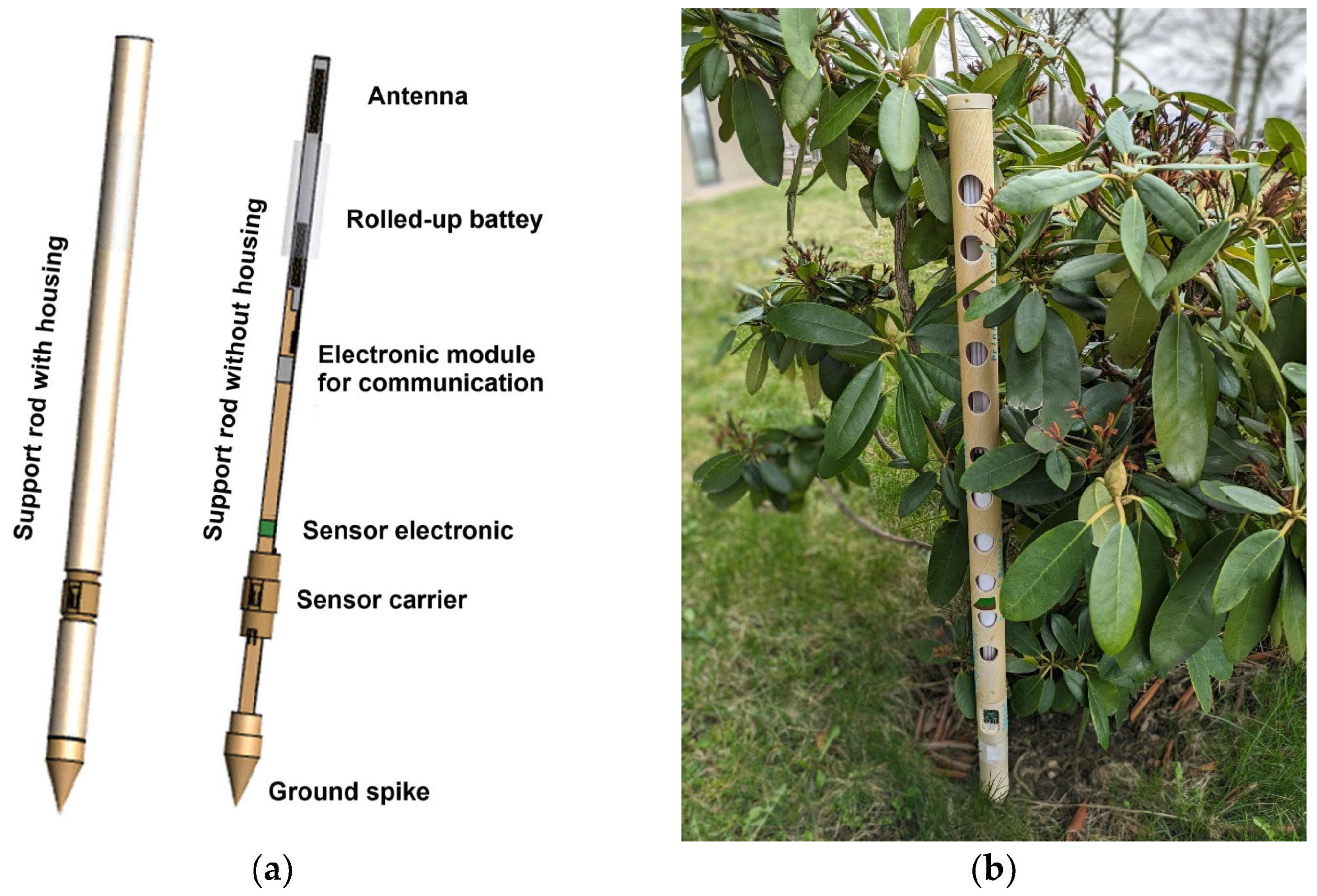
The EU project “PLANtAR” (https://plantar-project.eu/ (accessed on 13 May 2024)) aims to develop such cost-efficient, miniaturized, networked, and partly biodegradable monitoring electronics [16]. Figure 1 shows one of the sensors developed in the project, consisting of a miniaturized electronic module with a single-chip radio system, sensors for measuring temperature, soil tension, and nitrate [17]. The sensors and the electronic module are fabricated from materials that are biodegradable or inert with a minimum amount of metal and ceramic and allow for remaining them on the field when harvesting. The device is powered by a biodegradable zinc–manganese dioxide battery. For wireless communication, a printed antenna on paper is used. A gateway collects the data transmitted by the distributed sensor devices and brings it to the internet to a central server running an expert system.
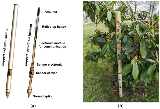
Figure 1.
Partly biodegradable sensor developed in EU project “PLANtAR”. (a) Structure of the sensor with all components for a wireless smart sensor system; (b) technology demonstrator of partially compostable sensors for agriculture.
2. Materials and Methods
2.1. Battery Configuration
The basic idea of realizing a printed flat zinc–carbon battery is depicted in Figure 2a. There is a layer-wise stacking of the required components: silver grid (optional), current collector, anode, electrolyte + separator, and cathode. A functional description can be found in [18,19]. The advantage of this printing approach is that the series connection of batteries can also be easily adapted by adjusting the layout. In Figure 2b, a series connection of three cells is shown, resulting in a total battery voltage of 4.5 Vnom. For this battery, just one side of two different substrates is used.
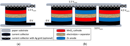
Figure 2.
Scheme of a printed zinc–carbon battery setup: (a) stack setup of a single cell; (b) series connection of 3 single cells realized by printing layout.
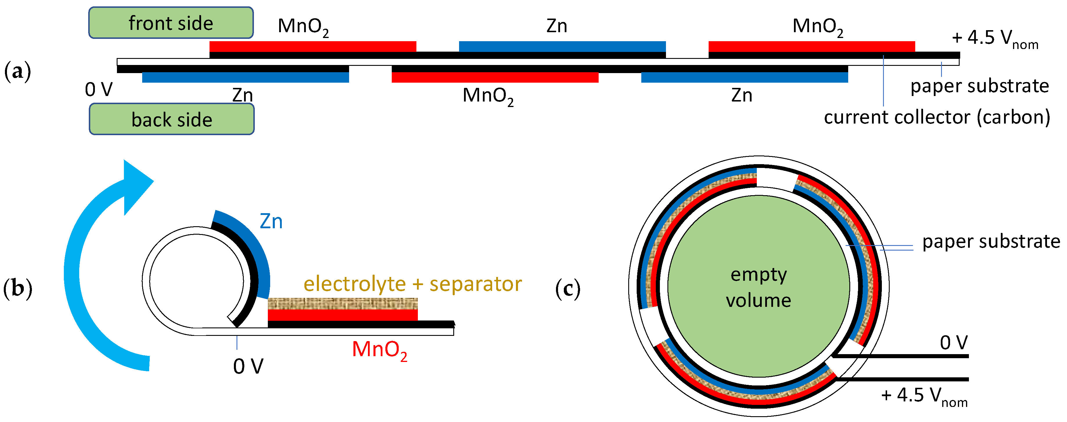
Following the basic approach in Figure 2, the layout can be slightly modified by printing all layers on just one substrate using the front and back sides (see Figure 3a). The relating anode and cathode layers will be overlapped adequately when rolling up the substrate (see Figure 3b).

Figure 3.
Scheme of a printed zinc–carbon battery setup: (a) stack setup of a 4.5 Vnom battery consistent of three cells; (b) beginning of roll-up, including electrolyte and separator layer; (c) rolled-up 4.5 Vnom battery from Figure 3a, pictorial schematic.
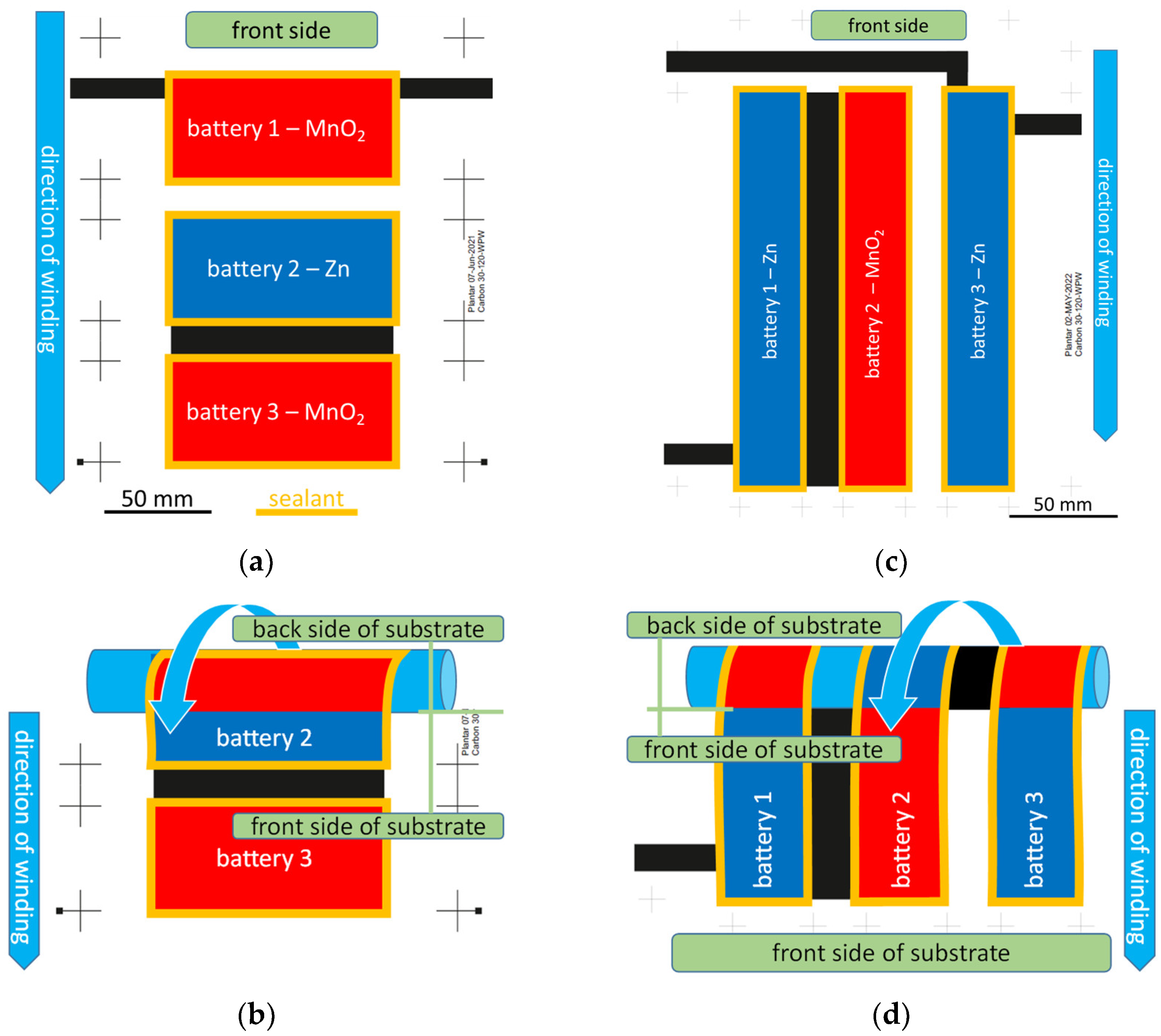
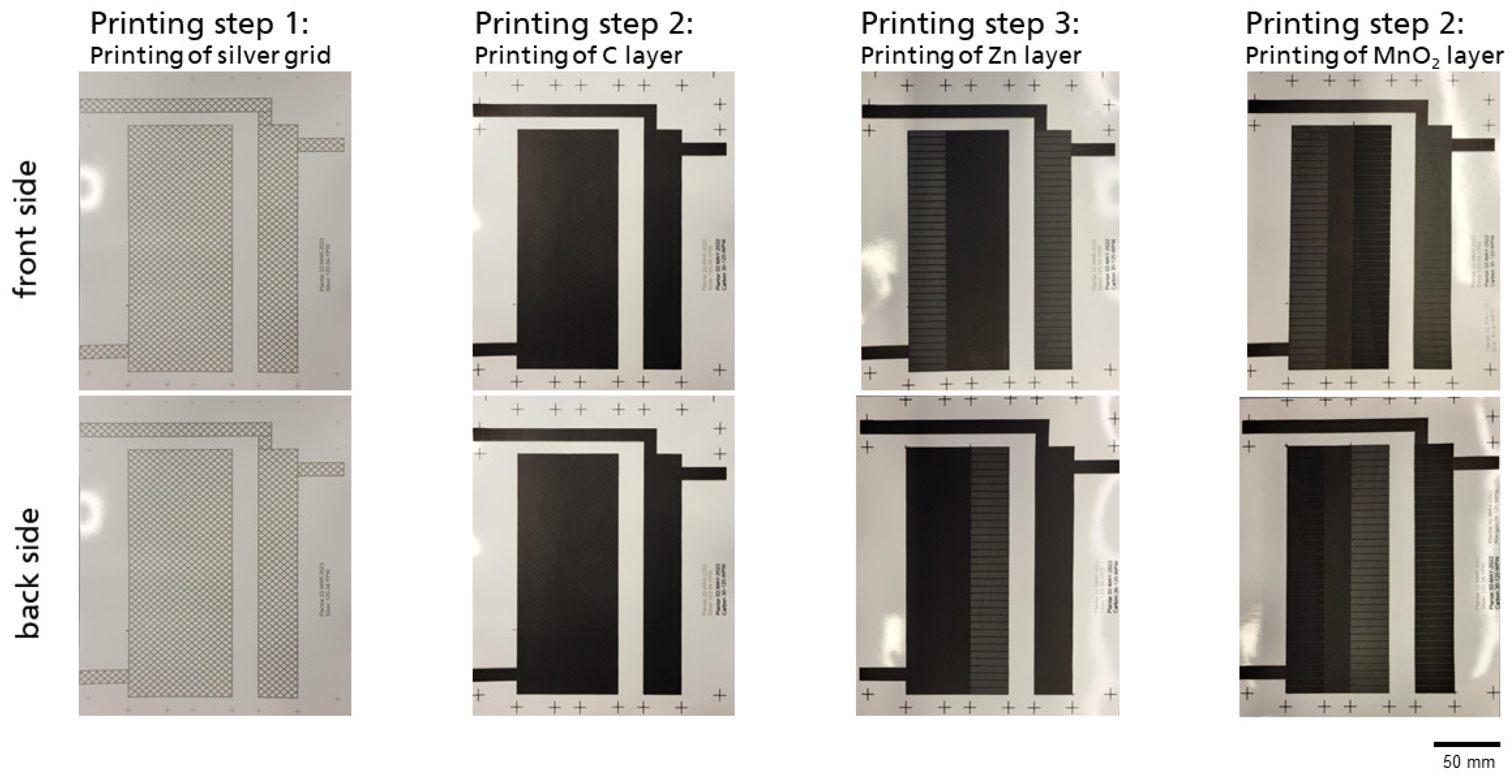
In the experiments, two different layouts have been used. In Figure 4a,b, the layout of three batteries is shown; they are arranged side by side in a winding direction (“crosswise”). This means that the sealing between the three cells is perpendicular to the winding direction. Each battery has an active area of 55 cm2. The second layout is shown in Figure 4c,d. Each battery has an active area of 57 cm2. The main difference in layout is that there is no longer any sealing between batteries across the winding direction (“lengthwise”). Instead, all sealings between the single battery cells are in the direction of the winding direction. The effect of this difference is described in the section Results. Photographs of the different layers of the lengthwise battery are shown in Figure 5.

Figure 4.
Scheme of two different 4.5 Vnom rolled-up battery layouts: (a,b) crosswise battery cells perpendicular to winding direction. (a) Shows the front side layout, while (b) shows the overlap when rolling up. (c,d) Lengthwise battery cells parallel to winding direction; (c) shows the front side layout, while (d) shows the overlap when rolling up.
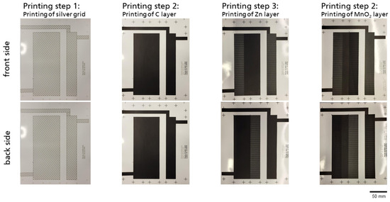
Figure 5.
Photographs of printed layers (from left to right: silver (optional), carbon, zinc, and manganese dioxide) on flat paper substrate for the lengthwise, three-cell 4.5 Vnom battery setup.
The reaction scheme of zinc, zinc chloride, and manganese dioxide is given in Equation (1):
4 Zn + 8 MnO2 + ZnCl2 + 9 H2O → (ZnCl2 · 4 ZnO · 5 H2O) + MnOOH
Environmental aspects have been discussed for different battery systems in [20]. Ref. [21] discussed sulfur dioxide leaching of spent zinc–carbon battery scrap. This was caused by steel encapsulation, especially of alkaline battery cells. In the printed batteries, neither NaOH nor steel is present.
2.2. Experimental Setup
For both layouts (see Figure 4), a set of three or four screens is manufactured for printing the silver (optional), carbon, zinc, and manganese dioxide layers. A screen-printing machine (EKRA E1 XL, IBE SMT Equipment, LLC, Magnolia, TX, USA) is used to print three or four layers: 1. a silver grid (DuPont PV410, DuPont, Wilmington, DE, USA) to lower the internal resistance of the battery (optional); 2. a carbon layer (Henkel Electrodag, Henkel AG & Co. KGaA, Düsseldorf, Germany) to cover the silver and prevent any chemical reaction of it with the battery cell; 3. a zinc layer as the anode of the battery; 4. a manganese dioxide layer as the cathode of the battery. After each printing step, the ink is fully dried in a convection oven (3D Micromac microDRY, 3D-Micromac AG, Chemnitz, Germany, 110 °C, 10 min) before applying the subsequent layer.
For the discharge of the fully manufactured battery, self-developed circuitry is used. The circuit has a stand-by current of 15 µA. It is about 1/667 of the current load of 10 mA (20 ms) for wireless data transmission. The firmware of the electronic circuitry is modified in a way that the wireless data transmission, which causes the highest current load for the battery, is conducted with a repetition nearly once a second (1.0064 s) instead of the application frequency of once every 30 min. The voltage is monitored during the discharge by a potentiostat (BioLogic VMP 3, BioLogic, Seyssinet-Pariset, France). This setup was chosen instead of also controlling the discharge by the potentiostat because inside the machine, mechanical relays are used to switch the discharge ON/OFF. Performing this thousands of times will decrease the lifetime of the device significantly.
2.3. Materials and Assembly Process
The focus of this paper is the roll-up of a flat materials system encapsulating an aqueous layer. To replicate and build on the published results, only the substrate and the encapsulation materials and methods are required. Material systems used for the production of printed batteries are hardly described in the literature. Due to the fact that ingredients and add-ons of the inks used are background knowledge of each actor in this field, we cannot unveil our recipes in this paper.
The substrate used for the experiments is Felix Schoeller “P_E:SMART paper type 1” (Felix Schoeller GmbH & Co. KG, Osnabrück, Germany). The main content is a raw paper covered by a resin coating avoiding the dry-out of the aqueous electrolyte. Therefore, only a small fraction of this material will remain with very slow degradation. By changing the substrate from 150 µm PET into P_E:SMART paper, the weight of polymer encapsulation could be reduced by more than 80%.
Having printed and dried the layers of silver (optional), carbon, zinc, and manganese dioxide, the electrolyte (gelled aqueous zinc chloride) and the separator (to avoid any short circuit between the anode and cathode inside the battery) as well as the encapsulation are missing to finalize and functionalize the primary battery system.
For the manual sealing of the cells, a 680 µm spacer of 3M 467MP 200MP coated with a glue layer on each side is employed. Alternatively, UV-curable glue (KIWOPRINT-UV 94, KIWO, Wiesloch, Germany) was screen-printed on the flat substrate. The assembly process was not successful, so there is no further reporting on these activities in this paper.
After fixing the sealant, a pre-cut porous paper was placed on the active battery areas and the electrolyte was applied by a syringe dispensing on that area, too.
For rolling up the battery layers, a rod was used to clamp one end of the substrate, enabling an open inner core after the procedure and the removal of the rod.
3. Results
In this chapter, the observations in building the rolled-up batteries and electrical performance data are given. The information is subdivided into three subsections: Section 3.1, Section 3.2 and Section 3.3.
3.1. Crosswise Battery
3.1.1. Battery Manufacturing
When winding up the crosswise battery setup, the pressure in this process caused the electrolyte within every battery cell to be pushed in the winding direction. This results in a wetting of the sealing bar between single cells. When the glue layer becomes wetted by the electrolyte, it loses its encapsulation capabilities. In consequence, the electrolyte of two cells is not separated as intended but connected. The result is a short circuit between the two battery cells by the electrolyte.
After many tries, it was concluded that the crosswise battery setup generates such severe problems with respect to encapsulation that a new approach to lengthwise battery layout was developed.
3.1.2. Electrical Performance
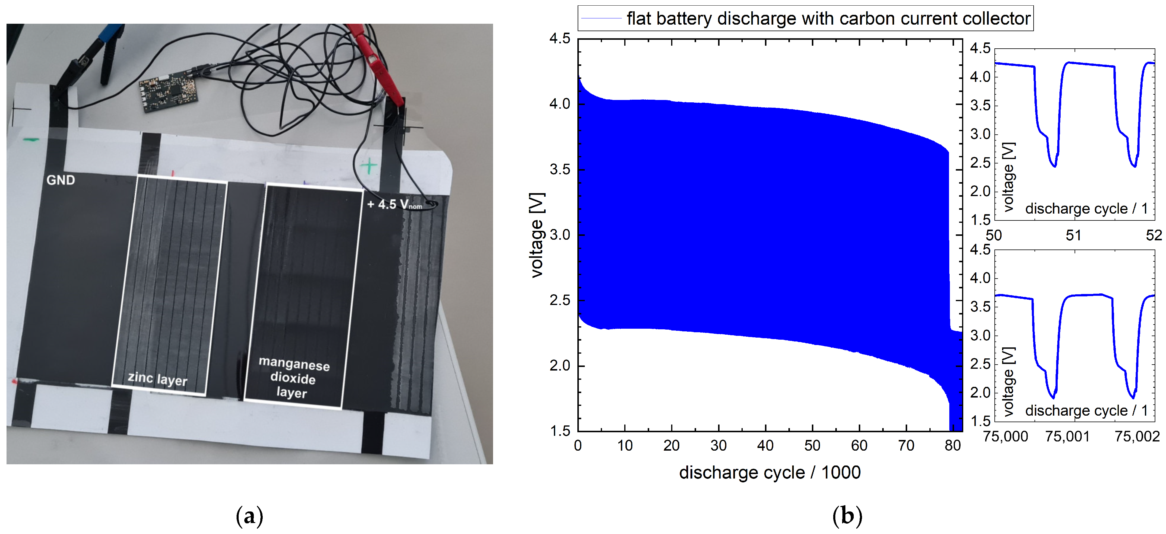
To have an idea of the battery performance, the non-winded battery was manufactured simply by the encapsulation of two flat substrates, which had been prepared already for the roll-up experiments. Using two of them, a battery of three cells in between them could be realized. In Figure 6a, the discharge setup with the external electronics is shown.
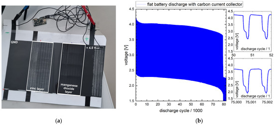
Figure 6.
Discharge setup of the crosswise battery in flat shape without roll-up. (a) Photo of the setup. The discharge electronics are connected via black wires. The potentiostat is connected via the black clamp and red clamp; (b) voltage diagram for 20 h of battery discharge.
In the discharge diagram recorded by the potentiostat shown in Figure 6b, two zones can be differentiated: up to cycle 78,000, the voltage of the battery fluctuates depending on the load level (15 µA vs. 10 mA) between an upper (4.2–3.7 V) and a lower level (2.4–1.9 V). In the higher voltage level, there is low power consumption of the electronics. During wireless data transmission, the current demand is highest, resulting in a decreased voltage level due to the internal resistance of the battery. At about 78,000 cycles (i.e., 21.8 °h), there is a significant drop in the voltage level from 3.7 V to 2.2 V. This drop indicates that one of the battery cells has reached its end of operation.
With >70,000 discharge cycles, the battery stays within the requirement of the application, which is defined as 20,000 cycles minimum.
3.2. Lengthwise Battery
3.2.1. Battery Manufacturing
When winding up the lengthwise battery setup, the pressure in this process caused the electrolyte within every battery cell to be pushed in winding direction as in the crosswise setup. The movement of the electrolyte can be controlled much better than in the first approach. By the exact dosing of the electrolyte during the winding up of the battery, two issues can be solved: 1. no wetting of the sealing stripes between the single battery cells; 2. no wetting of the sealing strips perpendicular to the winding direction at the closing end of the batteries. With this setup, it is possible to manufacture rolled-up batteries without internal shortages.
3.2.2. Electrical Performance
To have an idea of the battery performance, the non-winded battery was manufactured simply by the encapsulation of two flat substrates, which had been prepared already for the roll-up experiments. Using two of them, a battery of three cells in between them could be realized.
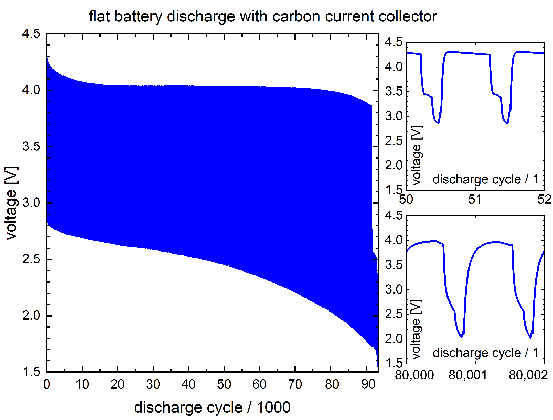
In the discharge diagram recorded by the potentiostat shown in Figure 7, two zones can be differentiated: from 0 to 90,000 cycles, the voltage fluctuated between an upper (4.3–4.0 V) and a lower level (2.9–2.0 V). At the higher voltage level, there is low power consumption of the electronics. During wireless data transmission, the current demand is the highest, resulting in a decreased voltage level due to the internal resistance of the battery. The electronics demand a minimum voltage level of 2.5 V. Therefore, the reliable operation is only in the range of 0 to 44,000 cycles. For the intended operation, the internal battery voltage should become lower. This can be realized by having a lower resistance in the current collector by a silver grid underneath. This modification is described in Section 3.3.

Figure 7.
Lengthwise battery: voltage diagram of battery discharge (flat battery setup).
At 90,000 cycles, this battery also shows a significant drop in the voltage level from 3.9 V to 2.5 V. This drop similarly indicates that one of the battery cells has reached its end of operation.
With >44,000 discharge cycles, the battery stays basically within the requirement of the application, which is defined as 20,000 cycles minimum.
3.3. Lengthwise Battery plus Silver Grid
3.3.1. Battery Manufacturing
The battery manufacturing is carried out similarly to the description given in Section 3.2.1. The only difference is that the layer stack has a silver grid underneath, also shown in Figure 5.
3.3.2. Electrical Performance
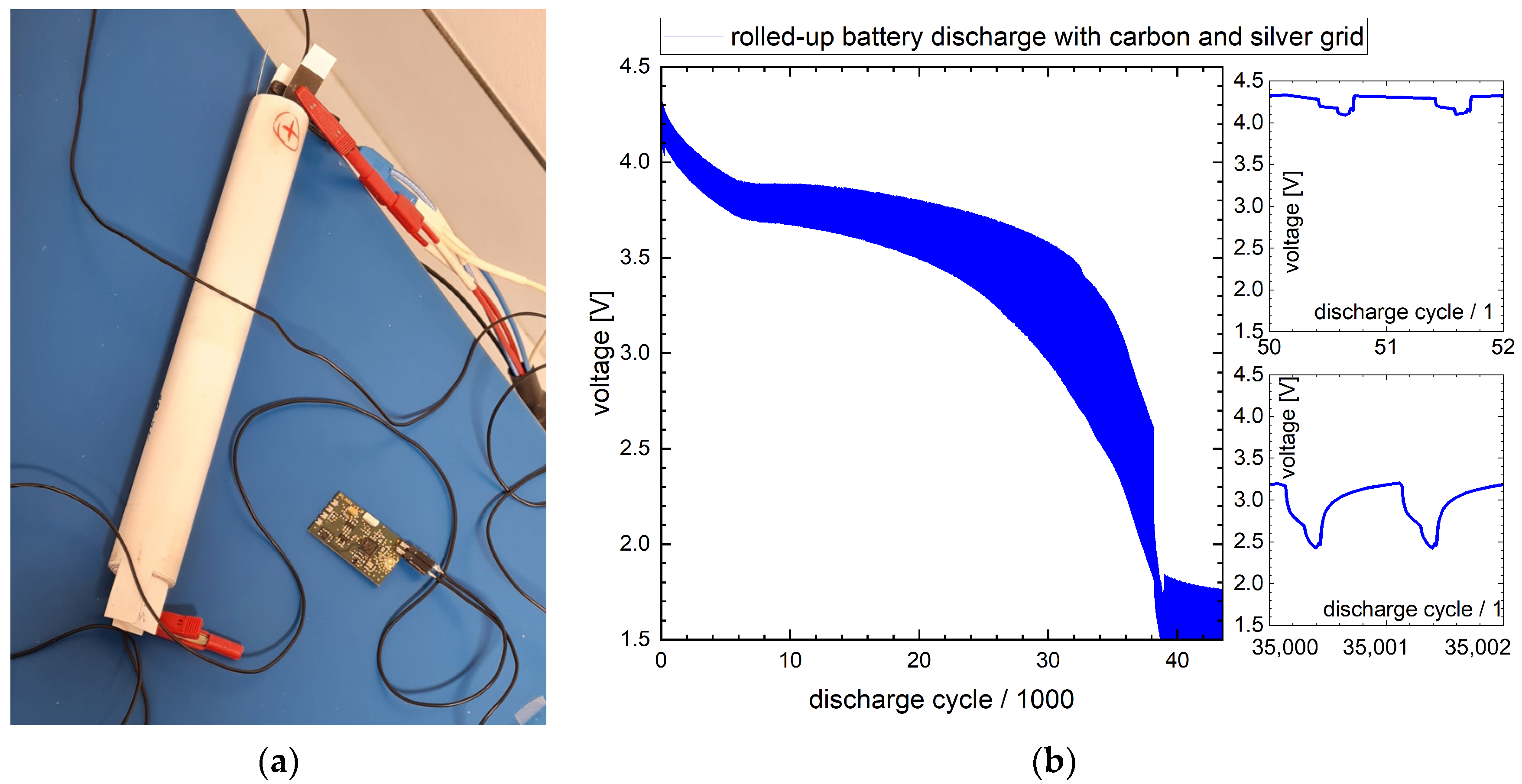
In this case, the battery performance was determined with a rolled-up battery, as shown in Figure 8a. The measurement results are given in Figure 8b. Due to less electrolyte inside the battery compared with the flat assembly of Section 3.2, the overall discharge cycles decrease from 44,000 to 34,000. This still matches the requirement of 20,000 cycles minimum.
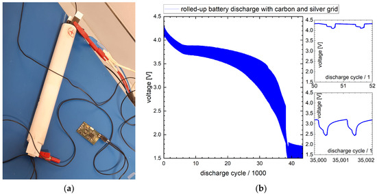
Figure 8.
Lengthwise rolled-up three-cell 4.5 Vnom battery with silver conductor grid: (a) discharge setup with electronics; (b) voltage diagram of discharge.
In the discharge diagram recorded by the potentiostat shown in Figure 8b, two zones can be differentiated: From 0 to 34,000 cycles, the voltage fluctuates between an upper (4.3–3.3 V) and a lower level (4.1–2.5 V). In the higher voltage level, there is low power consumption of the electronics. During wireless data transmission, the current demand is highest, resulting in a decreased voltage level due to the internal resistance of the battery. The electronics demand a minimum voltage level of 2.5 V. Therefore, the reliable operation is only in the range of 0 to 34,000 cycles.
At 38,000 cycles, this battery also shows a significant drop in the voltage level from 3.1 V down to 2.3 V. This drop similarly indicates that one of the battery cells has reached its end of operation.
With >34,000 discharge cycles, the battery stays basically within the requirement of the application, which is defined as 20,000 cycles minimum.
By this accelerated discharge setup, it is expected that the battery driving an application with less frequent discharge pulses will last longer, i.e., will enable more cycles because there is time for the battery to recover by ion reorganization. Therefore, the lifetime of the battery will be sufficient for the application.
4. Discussion
The research and development goal—to supply a rolled-up battery with an open inner core as a power supply for a sensor system for a dedicated agriculture application—was successfully reached. The main challenges, like the layout or the leakage of the battery’s encapsulation, were solved.
Comparing a printed battery in flat and the rolled-up form factor, the flat has a higher capacity compared with the rolled-up version. The main reason was found to be the lower amount of electrolyte stored inside the battery that is necessary for the chemical reaction. The amount of electrolyte is limited by the sealant’s thickness of 100 µm and the paper separator in between. The volume was 500 µL. In the flat form factor, there is no issue of bulging the paper substrate of the battery by a too-large electrolyte volume. The electrolyte volume was about 2 mL in each cell. In the rolled-up battery, this is not possible due to the layers that lie on top of each other in every ply.
The main challenge for rolling up any flat substrate is the tension caused inside any stacked material system due to different bending radii on the inner and outer sides of the substrate. When employing a relatively stiff encapsulation material, these limitations become even more obvious by small crinkles, causing the leakage of electrolyte. This is happening preferably in the glue layer that is weaker than any paper or polymer film layer.
For the application in agriculture, there are currently two drawbacks with respect to the biodegradability of the battery described in this article:
- The chemical system requires H2O in the electrolyte for the chemical reaction. Therefore, the electrolyte needs a hermetic sealing, which must withstand the aqueous electrolyte. This is realized by a polymer coating of the paper and a polymer frame with glue layers for encapsulation. These polymers must not be water-degradable and thus will remain in the soil for a long time.
- The resistance of the carbon electron carrier itself is too high. To deliver the required current for driving the electronics, an additional silver layer is required to lower the overall resistance of the current conducting layer. Silver is also non-degradable. Furthermore, sometimes silver ions are used to avoid any growth of bioorganic cells, such as dopants in sports clothing. A discussion review about silver in soil has been performed by [22].
5. Conclusions
In this paper, three important steps for designing and building a rolled-up printed primary battery are selected and described. For the first time, printed zinc–carbon batteries have not only been scaled with respect to voltage and capacity but also for three-dimensional shape. In this achievement, a primary battery printed on a paper substrate was rolled up to fulfill the application’s demand for an open inner core.
Author Contributions
Conceptualization, A.W. and S.V.; methodology, A.W. and T.Z.; validation, A.W. and S.V.; investigation, A.W., T.Z. and S.V.; resources, A.W. and T.Z.; writing—original draft preparation, A.W. and S.V.; writing—review and editing, A.W. and R.Z.; visualization, A.W.; supervision, R.Z.; project administration, A.W.; funding acquisition, S.V. and R.Z. All authors have read and agreed to the published version of the manuscript.
Funding
This research was funded by the Federal Ministry of Education and Research BMBF (contract 16ME0160).
Data Availability Statement
Dataset available upon request from the authors.
Conflicts of Interest
The authors declare no conflicts of interest.
References
- Gaikwad, A.M.; Steingart, D.A.; Nga Ng, T.; Schwartz, D.E.; Whiting, G.L. A flexible high potential printed battery for powering printed electronics. Appl. Phys. Lett. 2013, 102, 233302. [Google Scholar] [CrossRef]
- Hübner, G.; Krebs, M. Gedruckte Filmbatterien. Teme 2013, 80, 67–73. [Google Scholar] [CrossRef]
- Ji, X. A perspective of ZnCl2 electrolytes: The physical and electrochemical properties. eScience 2021, 1, 99–107. [Google Scholar] [CrossRef]
- Madej, E.; Espig, M.; Baumann, R.R.; Schuhmann, W.; La Mantia, F. Optimization of primary printed batteries based on Zn/MnO2. J. Power Sources 2014, 261, 356–362. [Google Scholar] [CrossRef]
- Nguyen, T.N.; Iranpour, B.; Cheng, E.; Madden, J.D.W. Washable and Stretchable Zn–MnO2 Rechargeable Cell. Adv. Energy Mater. 2022, 12, 2103148. [Google Scholar] [CrossRef]
- Nguyen, T.H.; Fraiwan, A.; Choi, S. Paper-based batteries: A review. Biosens. Bioelectron. 2014, 54, 640–649. [Google Scholar] [CrossRef] [PubMed]
- Wang, Z.; Winslow, R.; Madan, D.; Wright, P.K.; Evans, J.W.; Keif, M.; Rong, X. Development of MnO2 cathode inks for flexographically printed rechargeable zinc-based battery. J. Power Sources 2014, 268, 246–254. [Google Scholar] [CrossRef]
- Costa, C.M.; Gonçalves, R.; Lanceros-Méndez, S. Recent advances and future challenges in printed batteries. Energy Storage Mater. 2020, 28, 216–234. [Google Scholar] [CrossRef]
- Lanceros-Méndez, S.; Costa, C.M. Printed Batteries: Materials, Technologies and Applications; John Wiley & Sons: Hoboken NJ, USA, 2018. [Google Scholar]
- Boicea, V.A. Energy Storage Technologies: The Past and the Present. Proc. IEEE 2014, 102, 1777–1794. [Google Scholar] [CrossRef]
- Clement, B.; Lyu, M.; Sandeep Kulkarni, E.; Lin, T.; Hu, Y.; Lockett, V.; Greig, C.; Wang, L. Recent Advances in Printed Thin-Film Batteries. Engineering 2022, 13, 238–261. [Google Scholar] [CrossRef]
- Schmaltz, T.; Thielmann, A.; Neef, C.; Weymann, L.; Voß, P.; Wicke, T. Solid-State Battery Roadmap 2035+. Available online: https://publica.fraunhofer.de/handle/publica/417853 (accessed on 20 June 2024).
- Zhang, Y.; Zhu, Y.; Zheng, S.; Zhang, L.; Shi, X.; He, J.; Chou, X.; Wu, Z.-S. Ink formulation, scalable applications and challenging perspectives of screen printing for emerging printed microelectronics. J. Energy Chem. 2021, 63, 498–513. [Google Scholar] [CrossRef]
- Li, Y.; Qu, J.; Li, F.; Qu, Z.; Tang, H.; Liu, L.; Zhu, M.; Schmidt, O.G. Advanced architecture designs towards high-performance 3D microbatteries. Nano Mater. Sci. 2021, 3, 140–153. [Google Scholar] [CrossRef]
- Food and Agriculture Organization of the United Nations. How to Feed the World in 2050: Global Agriculture towards 2050. Available online: https://www.fao.org/fileadmin/templates/wsfs/docs/expert_paper/How_to_Feed_the_World_in_2050.pdf (accessed on 13 May 2024).
- Kurth, S.; Voigt, S.; Zichner, R.; Roscher, F.; Weigel, P.; Großmann, T. Technologies for biodegradable wireless plant monitoring sensors. In Proceedings of the Smart Systems Integration (SSI), Grenoble, France, 27–29 April 2021; pp. 1–4. [Google Scholar] [CrossRef]
- Voigt, S.; Willert, A.; Mende, W.; Zschau, T.; Oehme, T.; Zichner, R. Environmental friendly and low cost monitoring system for plant and agriculture fields. In Proceedings of the Smart Systems Integration (SSI), Bruges, Belgium, 28–30 March 2023; pp. 1–4. [Google Scholar] [CrossRef]
- Willert, A.; Killard, A.J.; Baumann, R.R. Tailored printed primary battery system for powering a diagnostic sensor device. J. Print Media Technol. Res. 2014, 3, 57–64. [Google Scholar]
- Willert, A.; Helmert, M.; Baumann, R.R. Printed Batteries Designed to Power OLED Applications. In Proceedings of the Smart Systems Integration (SSI), Munich, Germany, 9–10 March 2016. [Google Scholar]
- Dehghani-Sanij, A.R.; Tharumalingam, E.; Dusseault, M.B.; Fraser, R. Study of energy storage systems and environmental challenges of batteries. Renew. Sustain. Energy Rev. 2019, 104, 192–208. [Google Scholar] [CrossRef]
- Avraamides, J.; Senanayake, G.; Clegg, R. Sulfur dioxide leaching of spent zinc–carbon-battery scrap. J. Power Sources 2006, 159, 1488–1493. [Google Scholar] [CrossRef]
- Tsepina, N.; Kolesnikov, S.; Minnikova, T.; Timoshenko, A.; Kazeev, K. Soil Contamination by Silver and Assessment of Its Ecotoxicity. Rev. Agric. Sci. 2022, 10, 186–205. [Google Scholar] [CrossRef] [PubMed]

Disclaimer/Publisher’s Note: The statements, opinions and data contained in all publications are solely those of the individual author(s) and contributor(s) and not of MDPI and/or the editor(s). MDPI and/or the editor(s) disclaim responsibility for any injury to people or property resulting from any ideas, methods, instructions or products referred to in the content. |
© 2024 by the authors. Licensee MDPI, Basel, Switzerland. This article is an open access article distributed under the terms and conditions of the Creative Commons Attribution (CC BY) license (https://creativecommons.org/licenses/by/4.0/).