Article

A Novel Tire and Road Testing Bench for Modern Automotive Needs

Department of Civil and Industrial Engineering, University of Pisa, Largo Lucio Lazzarino 1, 56122 Pisa, Italy
*
Author to whom correspondence should be addressed.
Designs 2024, 8(4), 64; https://doi.org/10.3390/designs8040064
Submission received: 29 April 2024 / Revised: 31 May 2024 / Accepted: 18 June 2024 / Published: 24 June 2024
(This article belongs to the Section Vehicle Engineering Design)

Abstract

:
The automotive industry is currently transforming, primarily due to the rise of electric and hybrid vehicle technologies and the need to reduce vehicle mass and energy losses to decrease consumption, pollution, and raw material usage. Additionally, road surface manufacturers emphasize improving pavement durability and reducing rolling noise. This necessitates precise load condition definitions and drives the need for reliable wheel testing benches. Many current benches use abrasive-coated rollers or synthetic tapes, but devices capable of testing on actual road surfaces are rare. In this work, a novel device for testing tire-pavement interaction is proposed. The system features a cart moving along a closed-track platform, ensuring test repeatability and enabling structural durability tests on uneven surfaces with installed obstacles. The cart is equipped with a cantilever arm capable of supporting either a testing wheel with customizable dimensions and kinematic parameters or a tire integrated with a complete suspension system, moving along a customizable pavement surface. The system includes actuators and sensors for applying vertical loads and adjusting the alignment of the testing wheel (slip angle, camber angle, etc.), allowing the characterization of tire behavior such as wear, fatigue, rolling noise, and rolling resistance. Multibody simulations were performed to evaluate the bench’s feasibility in terms of kinematics, power requirements, and structural loads. Results confirmed how this novel test bench represents a promising advancement in tire testing capabilities, enabling comprehensive studies on tire performance, noise reduction, and the structural dynamics of vehicle subsystems.

1. Introduction

In the ever-evolving landscape of the automotive industry and road safety, the performance of tires stands out as a critical factor influencing vehicle dynamics and overall safety. The evaluation and optimization of tire performance through testing systems and methods play a pivotal role in enhancing the safety and efficiency of the entire vehicle.
As the automotive industry strives to expand the range of vehicles while maintaining consistent battery and motorization parameters, optimizing the efficiency of the entire vehicle system becomes imperative. This involves minimizing losses such as friction, tire rolling resistance, and mass, which is crucial for achieving extended vehicle range [1]. Additionally, the shift away from internal combustion engines highlights the importance of addressing new sources of vehicle noise, such as tire-road contact, structural component vibrations, and gear noise, which are expected to become predominant in the absence of traditional engine noise [2].
In order to optimize passenger comfort and address the changing dynamics of noise sources, a comprehensive study is needed to mitigate and harmonize vibrations. Furthermore, recent regulations targeting particulate emissions have underscored the significance of particulate generated by tire rolling wear, necessitating the development of highly accurate measurement equipment [3].
In this framework, prevalent tire testing machines comprise fixed benches installed in laboratories equipped with friction surfaces emulating asphalt conditions. This surface is typically obtained with a tape moving beneath the tire, similar to William J. Langer’s invention [4], or as cylinders coated with abrasive material, following the innovation by Kenneth, Oblizajek, Lauer, and Culp in [5]. While excelling in conducting comparative tests, these machines encounter limitations in their inability to interact with real asphalt, thereby introducing a disparity between experimental results and real-world driving scenarios. Concerning pavement testing, the prevalent structures are Accelerated Pavement Test (APT) systems, designed to simulate repeated passes over a pavement section and assess its fatigue [6,7,8]. Although these machines find applications in different scenarios, they are not traditionally employed for tire studies [9]. James F. Cuttino suggested a conceptually similar structure but with differences in its design [10,11]. Cuttino advocates for a raised metallic structure equipped with two rails and a measurement system positioned in the middle. Similarly, Matsumoto [12] proposed a comparable structure that, however, rests on three rails and features an open linear path, limiting its capacity for high speeds and frequent passes compared to closed-loop tracks.
This paper proposes a novel structure inspired by a train or roller coaster [13], comprising a guide made of cementitious material that constrains a cart for longitudinal movement. The cart moves over the pavement on four wheels, similar to a car, and features a system of wheels and springs that keep it aligned with the rail guide. The rail guide follows a closed-loop path and has a V-shape to prevent the cart from overturning. The closed-loop path, similar to a speedway circuit, includes two U-turns and two straight sections. Measurements are taken in the straight sections to avoid issues caused by the cornering slip angle. The system was designed under public funding from the University of Pisa in the framework of Project PRA 2022 30 and a patent was deposited [14]. The cart has an overhanging arm, resembling a double wishbone suspension, supporting the tested wheel. The tested wheel is connected to the overhanging arm through an articulated system, allowing for variations in slip angle and camber, and is motorized to adjust slippage. This design may allow the study of entire vehicle subsystems, such as automotive suspensions.
Furthermore, the paper explores the interaction between the tire and pavement, aiming to reduce rolling resistance by intervening in the pavement itself [15].
The closed loop structure, combined with a test speed of approximately 60 k m   h 1 , ensures repeatability for fatigue tests. An innovative aspect involves using real asphalt as pavement, allowing for diverse scenarios with different bituminous mixtures, gravel sections, irregularities, and climatic conditions.
The project’s objectives encompass analyzing contact mechanics to reduce tire rolling noise and rolling resistance, studying tire wear as well as road pavement damage, deriving force-slippage characteristics for different tire configurations, and simulating the structural dynamics of entire vehicle subsystems to optimize noise reduction and structural resistance to minimize the overall system mass.
The novelties introduced by the paper are as follows:
  • the monorail track; currently there are no closed-loop monorails that study both the pavement and the tire and allow the laying of any type of pavement with varying degrees of irregularities using conventional machines.
  • The monorail has a v-shape that efficiently transfers both vertical and horizontal forces to the ground.
  • The cart and its cantilever arm can support wheels from both lightweight vehicles and heavy-duty vehicles and can also support the entire vehicle’s subsystems.
The next sections are organized as follows: Section 2 describes the state-of-art equipment for testing tires and pavements, Section 3 focuses on the design of the track and the cart of the test bench proposed in this paper, Section 4 analyzes the results of the multibody model of the test bench.

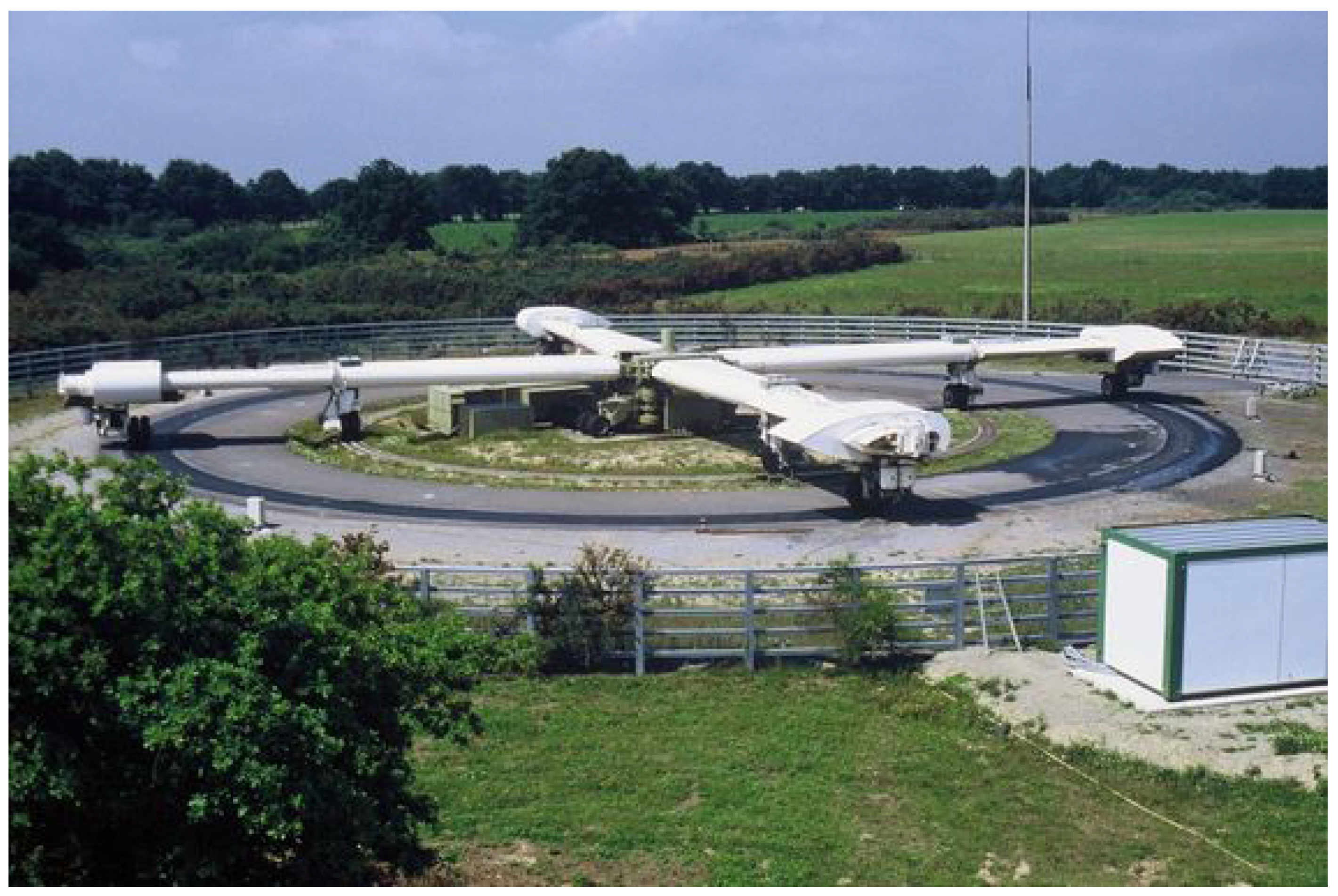
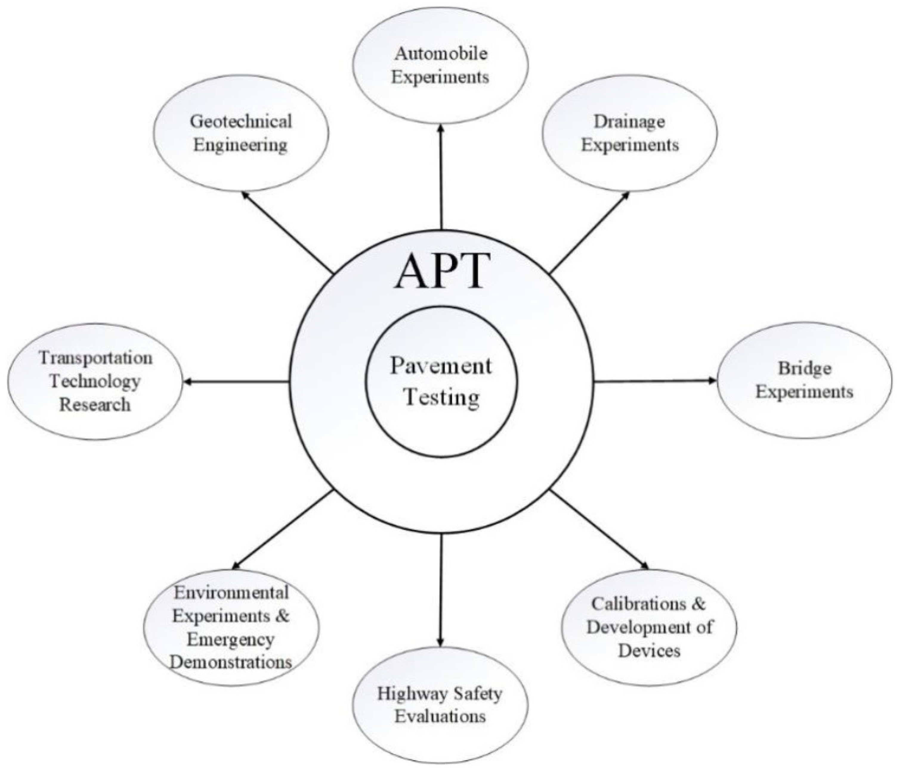
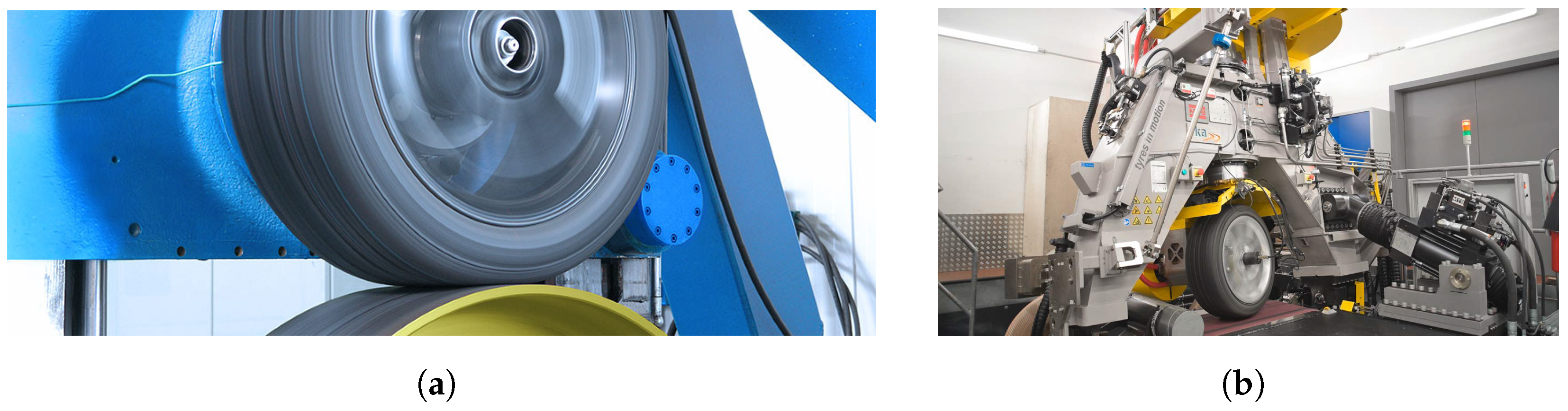
2. State-of-Art in Tyre and Road Testing

2.1. Pavement Testing

In the literature, many tests are performed to study pavement, with one of the most widely used facilities being Accelerated Pavement Testing (APT) structures. APT structures are mostly dedicated to pavement studies and only a few works investigate the tire behavior. APT structures can be broadly categorized into two sets: circular structures and linear structures. Circular structures are subjected to centrifugal loads, requiring careful consideration during the design phase, necessitate a larger available area for installation, and are not transportable. The primary advantage of circular structures lies in their high testing speed, enabling fatigue testing of pavements in less time [6]. An example is illustrated by the APT facility in Nantes, as shown in Figure 1.
Linear structures are more compact and allow for the development of vehicles or trailers equipped to transport the entire structure to various test surfaces. However, they are limited in achieving high testing speeds due to the restricted length of the straight section, consequently slowing down the execution of fatigue tests [7,8]. An example of two linear structures is depicted, one fixed in Figure 2a and one mobile in Figure 2b.
These are the most common applications of APT. As suggested in [9], APT facilities are also employed in other research areas unrelated to pavement studies. A summary of various applications is discussed in [9] and can be summarized by Figure 3.

2.2. Tire Testing

Regarding machines dedicated to tire studies, they can be broadly categorized into two main types: mobile benches and fixed benches. Mobile benches, as depicted in Figure 4, are typically trailers, towed by a driving unit along the test road. Internally, they feature a kinematic system that enables the necessary measurements for tire characterization in various configurations. One of the significant advantages of this type of machine is that it conducts measurements on segments of real pavement. However, drawbacks include the measurement point’s dependence on the driver’s trajectory and the inability to use it for tire studies on uneven surfaces, as both the trailer and the driving unit must traverse the measurement section. Fixed test benches are undoubtedly more reliable than mobile structures but do not conduct measurements on real pavement. Indeed, the most common test benches use either metal cylinders [5] or synthetic tape with abrasive coatings to simulate asphalt [4]. Two examples of fixed benches are shown in Figure 5.

3. Description of the Novel Test-Bench
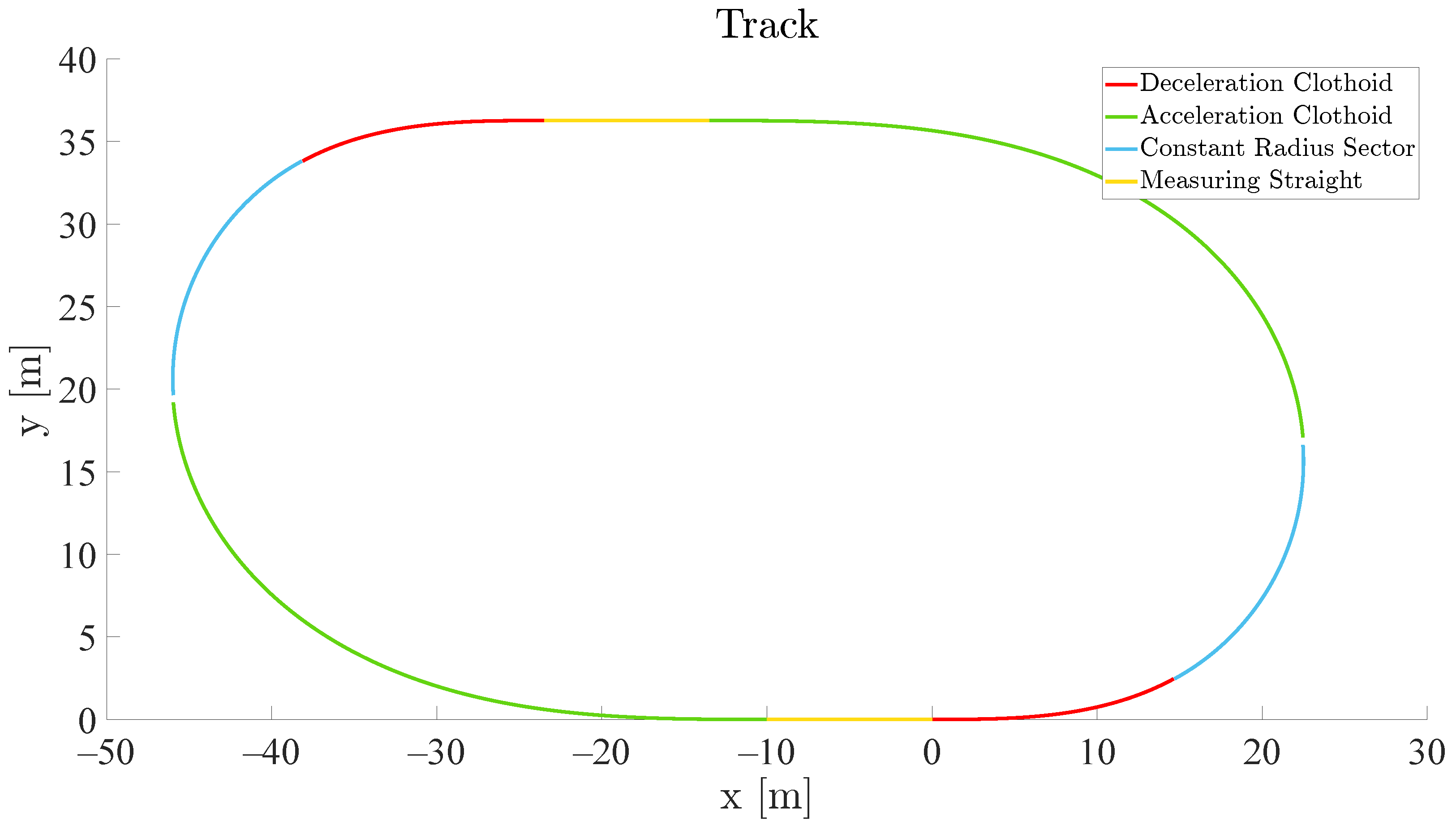
The proposed test bench involves a motorized cart moving along a monorail guide of reinforced concrete arranged as a closed path. The cart is then equipped with a cantilevered arm that holds the actual measuring apparatus [14]. A summary of the main features of the novel test bench compared to the available ones is shown in Table 1.
In the following, the components of the apparatus (i.e., the track and the cart) are described in detail.

3.1. Track/Platform

The layout and configuration of the guide structure have undergone a detailed examination aimed at minimizing centrifugal forces while effectively bearing the vertical forces acting on the tire. The testing path is derived from a flat surface measuring approximately 70 m × 30 m , visually presented in Figure 6. The path is segmented into four distinct sections, repeated twice: a measurement straight, a deceleration curve, a constant radius curve, and an acceleration curve:
  • The measurement straights, highlighted in yellow in Figure 6, serve as the phase for actual measurements at a constant travel speed of up to 60 k m   h 1 .
  • The deceleration curve is composed of a variable radius clothoid, connecting the straight segment to the section with the minimum constant radius. The utilization of the clothoid aims to seamlessly transition between the straight and minimum radius curve, providing an optimized compromise between centrifugal force and travel speed.
  • The constant radius part where constant velocity is imposed has a threshold that is computed to obtain acceptable centrifugal loads.
  • The acceleration curve segment comprises a clothoid linking the constant radius curvature segment to the second straight. The longer length of the acceleration segment, compared to the deceleration segment, is justified by the driving power being lower than the braking power.
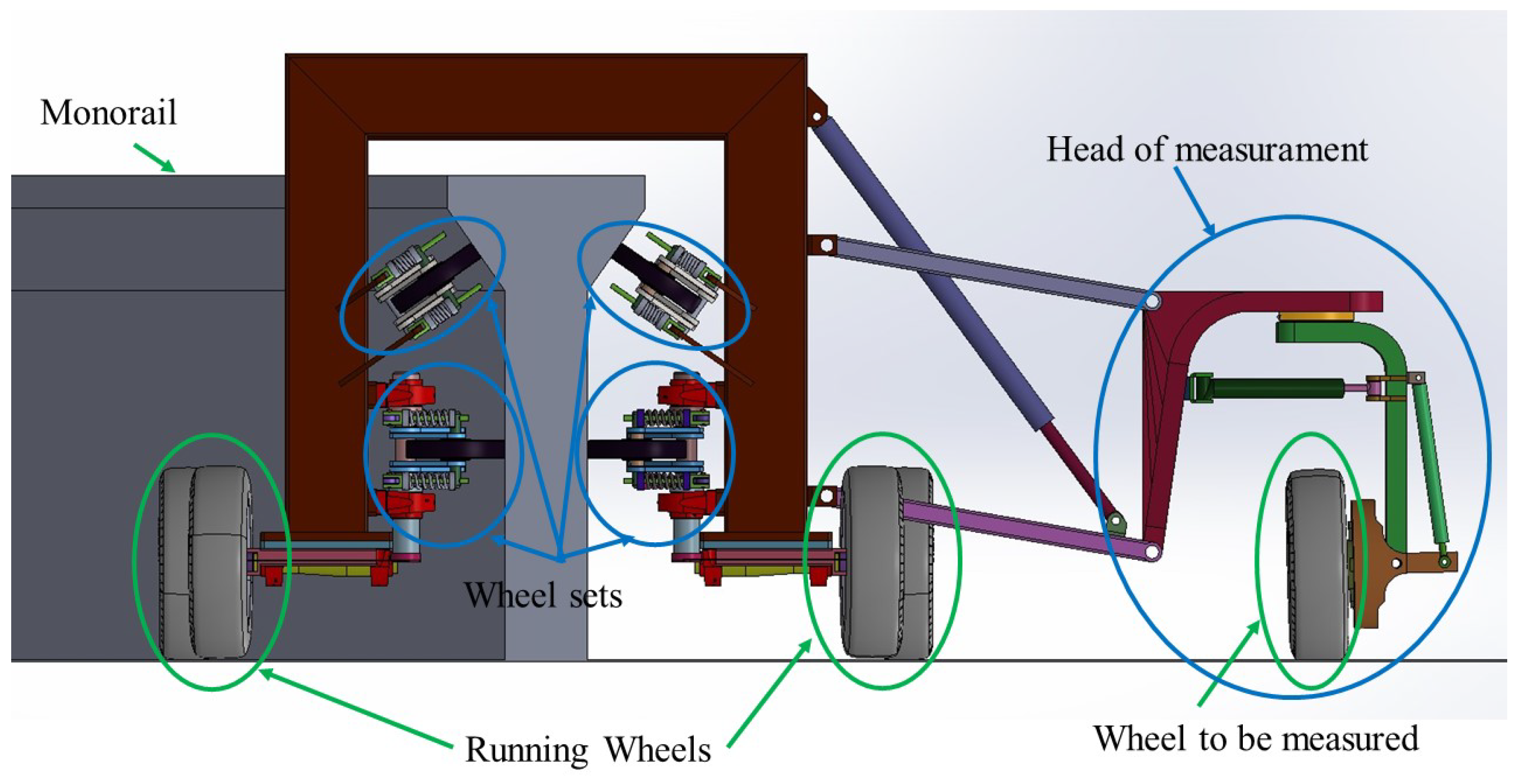
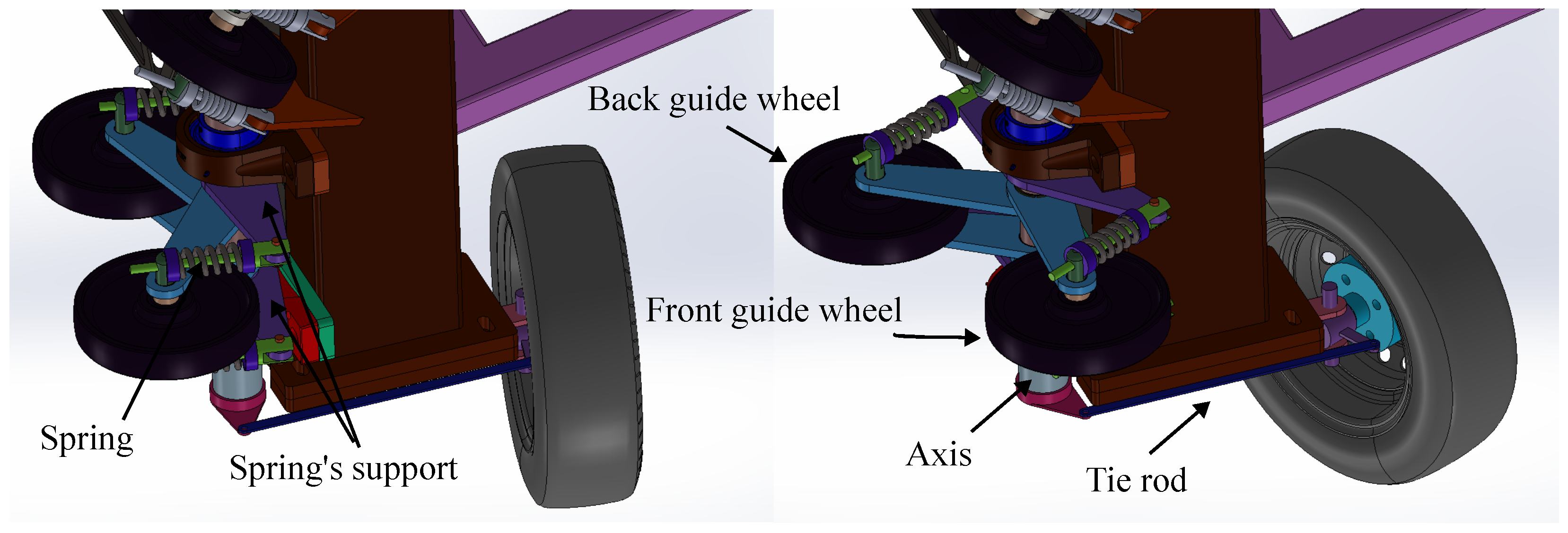
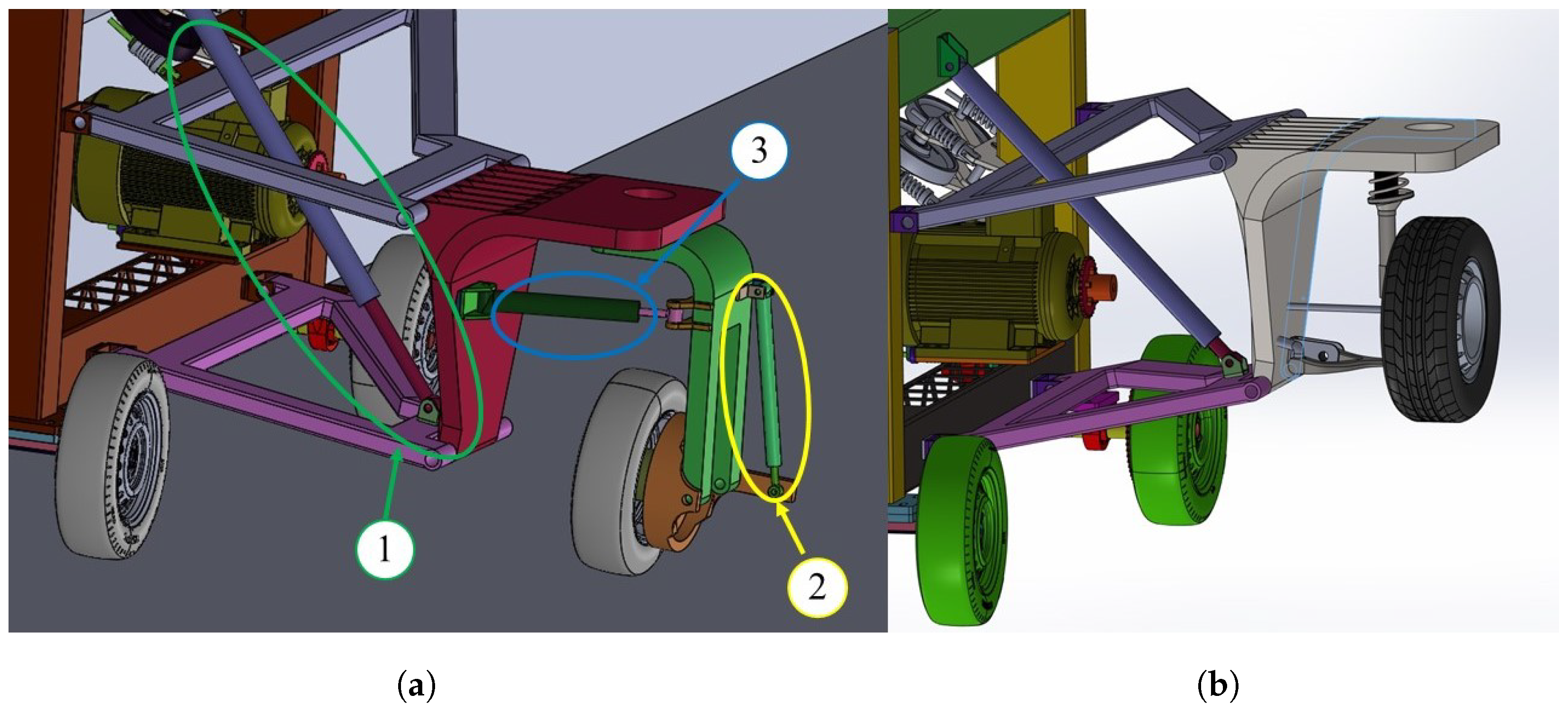
In order to perform tests in different wetting conditions, with different water film thicknesses, the straight section of the track can be equipped with an artificial wetting system, composed of equally spaced nozzles and a water pump that can tune the water flow to achieve the desired film thickness. For this reason, the straight section of the pavement is designed with a minimum transversal grade, toward the inner side, equal to 0.5%. The water is collected at the inner side and reused circularly in the wetting system. The entire facility can be covered, and the straight sections can be climate-controlled to simulate extreme weather conditions.
In order to reduce the horizontal component of the centrifugal force acting on the guide, the transversal section of the pavement on the circular curves can be designed with higher values of the transversal grade toward the inner side, up to 7%, whilst on the clothoids the transversal grade is changed linearly from 0.5% to 7%.
Pavements can be instrumented with strain gauges, pressure cells, and thermocouples to monitor pavement strain and temperatures during tests; data on pavement layer deformation and asphalt temperatures are essential to evaluate pavement response under heavy loads.
The cementitious monorail, depicted in gray in Figure 7, is designed to minimize construction costs with respect to metallic rails. It features a vertical central body supporting horizontal forces (centrifugal force) and an upper V-shaped section to efficiently transfer both vertical and horizontal forces to the ground. The inclination angle of the V-shape represents a compromise between construction and mechanical requirements. Vertical force on the tire and the entire measuring apparatus is applied through a hydraulic or electric piston, selected for its flexibility in adjusting forces during the run, as opposed to using fixed masses that would burden the cart during curves.
The monorail design was preferred over a double rail due to construction simplicity and cost-effectiveness. A double rail would require meticulous construction to avoid excessive backlash and would substantially increase the construction costs of the rails and the pavement. The monorail design, on the other hand, offers simplicity in both construction and mechanical constraint management.

3.2. The Cart

The cart part of the apparatus is comprised of a portal frame, as illustrated in Figure 7, supported by four wheels, denoted in green, spanning the monorail. The cart is designed to traverse the monorail through eight wheel sets, among which four are located in the central body and an additional four are positioned in the inclined section of the monorail. Each wheelset is equipped with two pivoting wheels, supported by springs to effectively mitigate rail irregularities, ensuring secure contact and preventing detachment or undue overload.
The propulsion system is a critical component, featuring two motors situated on both the internal and outer sides. Torque is transmitted to the rear running wheels of the cart using a chain drive mechanism, ensuring smooth and controlled motion along the monorail. The electrical power can be delivered to the cart with sliding contacts or, in non-durability tests, with an onboard battery.
Two A-arms connect the measurement apparatus with the cart like a double wishbone-type suspension system. This configuration allows for optimal flexibility and stability during testing. The application of vertical force is accomplished through a hydraulic piston mechanism, connecting the lower end of the A-arm to the cart, providing a controlled and precisely adjustable force.
Each wheelset, composed of two wheels, can pivot about an axis, which allows the running wheel to auto-steer during the turn as shown in Figure 8. In particular, the front guide wheel and the back guide wheel of the horizontal wheelset have the same springs, so the axis rotates keeping the spring’s support tangential to the monorail. Then, a tie rod connects the wheelset support to the running wheel so that when the set turns along its pivot axis, the running wheel turns with it.

3.3. Sensors and Head of Measurements

As mentioned in the previous paragraphs, the test bench is capable of measuring numerous parameters related to both the tire and the pavement. To this end, as illustrated in Figure 9a, it is possible to conduct tire measurements using the articulated system, which allows for variations in camber, using the camber actuator no. 2, and steering angle, using the steering actuator no. 3, and an integrated hub motor to deliver torque to the wheel for measurements in response to slip. Element no. 1, as mentioned in the previous paragraph is the vertical force actuator.
The apparatus can be equipped in the head of measurement to perform various tire measurements, which may include the following exemplifying elements (See Table 2):
  • Two laser Doppler sensors, installed on the wheel support and having an angle of 90° between them, pointed at the pavement for measuring the direction and the value of the speed of the head of the measurement with respect to the pavement.
  • Three laser sensors, installed on the wheel support, point at the pavement for the reconstruction of the plane of the pavement and consequently the orientation of the tire to be studied. The system of laser sensors can be integrated with more sensors, at least five sensors, mounted on a beam to record pavement deflections at different distances, generally on the rear of the wheel at 300, 450, 600, 900 and 1200 m m . These deflections can be used for the dynamic identification of the pavement structure and to evaluate structural damage under heavy loads.
  • An LVDT (Linear Variable Differential Transformer) sensor, installed parallelly to the tie rod, allows the evaluation of the steering angle of the wheel (and consequently the tire slip angle).
  • A rotational Hall sensor for evaluating the angular velocity of the wheel to be measured.
  • A series of strain gauges, as illustrated in [19], allow the evaluation of the forces between the tire and the pavement based on the suspension rods’ deformation.
  • Microphones for the estimation of the noise by the Close Proximity Method [20,21].
The structure exhibits a notable rigidity, so that various tire parameters such as camber and slip remain relatively constant within the measurement section, as will be further analyzed subsequently. In Figure 9b, an example of a McPherson suspension installation on the measurement head is also depicted. During the tests of the suspension system, the vertical force actuator is kept fixed and the vertical motion of the suspension is due to the suspension’s shock absorber.

4. The Multibody Model

In order to achieve significant data for the detailed design of the whole system, a multibody model was developed in MSC Adams to provide a more accurate estimation of loads. This model originated from the machine layout defined in the CAD model. All elements and parts with assigned density were imported, together with various joints and springs. Tires with properties specified in a TIR file were added to simulate contact with the road for both the running wheels and the wheel to be measured.
To reduce the computational effort required by the simulation, the wheel sets were modeled with simple contacts between smooth and frictionless surfaces and without rotation. As previously mentioned, the multibody model is not as accurate as an advanced analysis model and this is not the aim of this work. However, it serves as a preliminary study to better estimate layout and costs. The simulation starts from a stationary position, with the cart positioned at a point along the measurement straight. Subsequently, a vertical load is applied to the measured wheel, and a constant torque is applied to the two drive wheels until the test speed is reached, e.g., a maximum of approximately 60 k m   h 1 . The torque to the drive wheels is controlled through a closed-loop speed control aimed at keeping a constant 60 k m   h 1 speed.
The simulation runs for 60 s , allowing the cart to complete about four laps of the circuit. In order to compute the baseline loads acting on the structure, neglecting the effects of the loads due to the tested tire, the slip angle of the wheel to be measured was set to 0. A target speed profile was imposed in order to reach the maximum speed which was kept constant along the whole track. The vertical force applied on the wheel to be measured is about 30 kN.
The power needed to propel the cart arises from various factors, including the inertia of the cart, rolling resistance, and the slip angle of all four running wheels and the wheel being measured. Figure 10 illustrates the power requirements for moving the cart along the monorail in two scenarios: the first with all four running wheels fixed during the simulation, and the second with the steering system, as discussed in Section 3.2, applied to each running wheel. The graph indicates that initially, along the straight path, the velocity and power profiles of both cases perfectly coincide. However, as the cart approaches the turn, the fixed-wheel system encounters increased resistance, leading to a deviation in power and velocity compared to the steering wheel case. In the scenario with steering wheels, the cart attains the test speed earlier. Regardless of the imposed constant speed in both cases, whenever the cart approaches a turn, the speed decreases solely due to dissipative effects. Figure 10 demonstrates that incorporating a simple steering system (Figure 8) can result in approximately a 30% reduction in peak power during the constant speed phase of the test. Further insights into the simulation’s maneuver with steering wheels are presented in Figure 11, where the color bar distinguishes each section of the circuit, as described in Figure 6. The energy consumption is approximately 220 kJ per lap at maximum speed. The cart is powered by electrical energy, resulting in lower local carbon emissions compared to mobile test systems like truck trailers or other facilities that require internal combustion engines. Although the structure is considerably heavier than an indoor test bench, leading to greater power absorption during tests, an energy recovery system can be installed during tire slip tests to reduce power consumption. The use of cementitious material for the rail and simple beams for the cart chassis are examples of technical decisions made to reduce construction costs. Compared to other APT facilities, the costs are similar; however, it is indeed more expensive than indoor test benches.
Another result confirming the suitability of the designed test bench is the slip angle of the wheel to be measured. In Figure 11, the slip angle of the measured wheel is represented in blue, and the cart velocity is depicted in green. The valleys in the slip angle curves correspond to the turns in the track, while the peaks indicate straight sections. Notably, the slip angle remains constant and close to zero during the straight portion of the measurement zone. This ensures accurate measurements when conducting experiments to obtain tire characteristic curves, such as force versus slip angle.
Figure 12 illustrates the forces applied to the front guide wheel (Figure 8) of each of the horizontal wheel sets (internal and external). The force applied to the inner guide wheel is represented in blue, while the force applied to the outer one is depicted in red. Initially, the two curves overlap, then they diverge due to the vertical force applied to the test wheel. Due to the layout of the guide wheels, this force causes the internal wheel to bear a greater load than the outer one.
Furthermore, Figure 12 shows that the given preload is high enough to prevent detachment of the external wheel during the traversal of corners (force value in the red curve valleys always greater than zero). Such preload might appear too high, but it contributes to preventing excessive loading on the inclined guide wheels.
Other simulations are conducted to better estimate the loads during tests on uneven pavements and bumps. The simulation control parameters are the same as in the previous tests, but the pavement is different. Only a portion of the simulation is shown to facilitate a more detailed analysis of the graphs. Figure 13a shows the forces on the inner and outer springs, which are represented in blue and red, respectively. The simulation analyzes the tested wheel encountering a bump on the straight section (green circle). Figure 13b shows the tested wheel running on an uneven stochastic pavement throughout a sector of the lap. In both cases, the cart shows smooth behavior during the tests, without causing overloads, detachements, or excessive vibrations.

5. Conclusions

This paper addresses the critical role of tire performance in the automotive industry’s evolving landscape and underscores the necessity for comprehensive testing systems to enhance vehicle safety and efficiency. The proposed testing system, along with its preliminary design, aims to study tire-road interactions and specifies the required instrumentation for accurate measurements. The key points of the novel test bench can be summarized as follows:
  • The structure features a closed-loop track with an equipped and instrumented cart moving along a single rail made of reinforced concrete, facilitating the evaluation of road surface and tire wear, and force-slippage characteristics under realistic conditions. The system is also able to measure tire-road rolling noise and monitor strains in pavement layers and surface deflections to evaluate pavement response and structural damage.
  • The novel test bench stands out for its capability to replicate real pavement conditions, accommodating diverse scenarios with different bituminous mixtures, unevenness, and climatic conditions, particularly water film thickness.
  • This design addresses the limitations of existing tire testing machines, which often fail to accurately reproduce interactions with in-service pavements, thereby bridging the gap between laboratory experiments and real-world driving.
  • The closed-track structure, together with the electric power supply, allows tire testing to be more ecological by significantly reducing carbon emissions compared to conventional mobile test systems. Moreover, the incorporation of an energy recovery system during tire slip tests enables further reduction in power consumption, enhancing the sustainability of the testing process. However, it is important to note that the heavier structure of the test bench may lead to higher power absorption during tests, potentially increasing operational costs.
  • Despite the high initial investment required for building the structure, which may still exceed the costs of indoor test benches, even with measures to mitigate construction expenses, the operational costs and energy consumption are projected to be comparable with traditional lab testing machines. Moreover, the inclusion of in-service pavement testing provides an additional advantage, further justifying the initial investment.
  • The detailed engineering approach minimizes centrifugal forces and ensures secure contact between the measuring apparatus and the pavement.
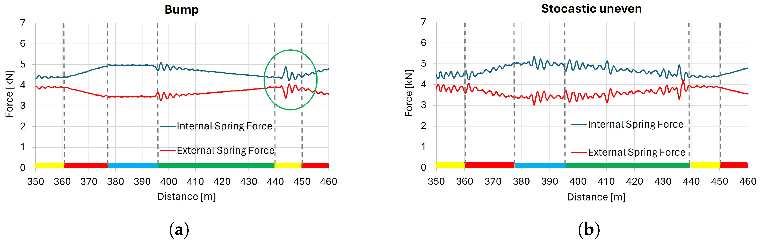
  • Simulation results validate the design, showing significant reductions in peak power during constant and maximum test speed movements and supporting stability for obtaining accurate tire characteristic curves.
In conclusion, the novel test bench presents a promising advancement in tire testing capabilities, enabling comprehensive studies on tire performance, noise and rolling resistance reduction, and the structural dynamics of vehicle subsystems and pavement structures.

Author Contributions

Conceptualization, F.F. (Francesco Favilli), F.B., F.F. (Francesco Frendo), P.L. and M.L.; methodology, F.F. (Francesco Favilli); software, F.F. (Francesco Favilli) and M.S.; writing—original draft preparation, F.F. (Francesco Favilli) and M.S.; writing—review and editing, F.F. (Francesco Favilli), M.S., F.B. and F.F. (Francesco Frendo); supervision, F.B., F.F. (Francesco Frendo), P.L. and M.L.; funding acquisition, F.B. and M.L. All authors have read and agreed to the published version of the manuscript.

Funding

This research was performed in the framework of the project PRA 2022 30, funded by the University of Pisa.

Data Availability Statement

Data will be made available on request.

Conflicts of Interest

The authors declare no conflicts of interest. The funders had no role in the design of the study; in the collection, analyses, or interpretation of data; in the writing of the manuscript; or in the decision to publish the results.

References

  1. Holmberg, K.; Andersson, P.; Nylund, N.O.; Mäkelä, K.; Erdemir, A. Global energy consumption due to friction in trucks and buses. Tribol. Int. 2014, 78, 94–114. [Google Scholar] [CrossRef]
  2. Iversen, L.M.; Marbjerg, G.H.; Bendtsen, H. Noise from Electric Vehicles–‘State-of-the-Art’ Literature Survey. 2013. Available online: https://api.semanticscholar.org/CorpusID:218654178 (accessed on 8 May 2024).
  3. Forte, A. Review of the last draft requirements of the Euro 7 emissions standard and their impact on light-duty car manufacturers. In Proceedings of the 2023 IEEE International Workshop on Metrology for Automotive (MetroAutomotive), Modena, Italy, 28–30 June 2023; IEEE: Piscataway, NJ, USA, 2023; pp. 7–12. [Google Scholar]
  4. Langer, W.J. Flat Belt Tire Tester. U.S. Patent 4 238 954 A, 23 February 1979. [Google Scholar]
  5. Oblizajek, K.L.; Lauer, C.; Culp, E.H. Tire Testing Apparatus. U.S. Patent 4 593 557 A, 26 February 1985. [Google Scholar]
  6. Nguyen, M.L.; Chazallon, C.; Sahli, M.; Koval, G.; Hornych, P.; Doligez, D.; Chabot, A.; Le Gal, Y.; Brissaud, L.; Godard, E. Design of reinforced pavements with glass fiber grids: From laboratory evaluation of the fatigue life to accelerated full-scale test. In Accelerated Pavement Testing to Transport Infrastructure Innovation: Proceedings of 6th APT Conference; Springer: Berlin/Heidelberg, Germany, 2020; pp. 329–338. [Google Scholar]
  7. Zhang, W.; Macdonald, R.A. The Danish Road Testing Machine 1995–2000. In Proceedings of the International Conference on Accelerated Pavement Testing, Reno, NV, USA, 18–20 October 1999. [Google Scholar]
  8. Romanoschi, S.; Scullion, T. Validation of the Maximum Allowable Amounts of Recycled Binder, RAP, and RAS Using Accelerated Pavement Testing-Interim Report; Technical Report; Texas Department of Transportation, Research and Technology Implementation Office: Houston, TX, USA, 2014.
  9. Fosu-Saah, B.; Hafez, M.; Ksaibati, K. A Review of Accelerated Pavement Testing Applications in Non-Pavement Research. CivilEng 2021, 2, 612–631. [Google Scholar] [CrossRef]
  10. Cuttino, J.F. Tire Testing Systems and Methods. U.S. Patent 8 474 311 B2, 2 July 2013. [Google Scholar]
  11. Cuttino, J.F. Tire Testing Systems and Methods. U.S. Patent 8 806 931 B2, 19 August 2014. [Google Scholar]
  12. Matsumoto, S.; Miyashita, H.; Murauchi, K.; Hasegawa, M.; Sakagami, T. Tire Testing Device. Patent JP 2022 009 437 A, 4 August 2022. [Google Scholar]
  13. Bucchi, F.; Frendo, F.; Bavaresco, F.; Conte, G. Multibody simulation of a rope-driven automated people mover. Proc. Inst. Mech. Eng. Part F J. Rail Rapid Transit 2018, 232, 2173–2185. [Google Scholar] [CrossRef]
  14. Bucchi, F.; Losa, M.; Frendo, F.; Favilli, F.; Leandri, P. Apparecchiatura e Impianto per Testare Sottosistemi Comprendenti Ruote di Veicoli e Pavimentazioni per Infrastrutture di Trasporto su Gomma. Patent B10/1747 no. 102023000028446, 29 December 2023. [Google Scholar]
  15. Santero, N.; Loijos, A.; Ochsendorf, J. Greenhouse gas emissions reduction opportunities for concrete pavements. J. Ind. Ecol. 2013, 17, 859–868. [Google Scholar] [CrossRef]
  16. ika—RWTH Aachen University. Mobile Tyre Test Rig “FaReP”. Available online: https://www.ika.rwth-aachen.de/en/competences/equipment/test-benches/farep-en.html (accessed on 10 April 2024).
  17. FKA. Cornering and Traction Test Rig MTS Flat-Trac IV CT Plus. Available online: https://www.fka.de/en/testing/chassis/112-cornering-traction-test-rig-mts-flat-trac-iv-ct-plus.html (accessed on 10 April 2024).
  18. Kistler Group. Measuring and Test Systems for the Tire Industry—Take Full Advantage of Top Performance. Available online: https://www.kistler.com/US/en/tire-327testing/C00000072 (accessed on 10 April 2024).
  19. Batistini, L.; Donati, S.; Nori, M.; Tirabassi, L.; Bucchi, F.; Frendo, F. Suspension and tyre loads estimation of an FSAE car: Model development and on-track validation. Veh. Syst. Dyn. 2024, 1–22. [Google Scholar] [CrossRef]
  20. Losa, M.; Leandri, P.; Licitra, G. Mixture design optimization of low-noise pavements. Transp. Res. Rec. 2013, 2372, 25–33. [Google Scholar] [CrossRef]
  21. Li, T. A state-of-the-art review of measurement techniques on tire–pavement interaction noise. Measurement 2018, 128, 325–351. [Google Scholar] [CrossRef]
Figure 1. The pavement testing facility of IFSTTAR Nantes [6].
Designs 08 00064 g001
Figure 2. APT structures. (a) Fixed linear APT structure [7]. (b) Mobile linear APT structure [8].
Designs 08 00064 g002
Figure 3. Schematic of pavement and non-pavement research applications of APT facilities [9].
Designs 08 00064 g003
Figure 4. Mobile tyre test bench of the Institute of Automotive Engineering (ika) of RWTH Aachen University [16].
Designs 08 00064 g004
Figure 5. Indoor tire’s test benches. (a) Drum type test machine (Source: Kistler Group) [17]. (b) Flat belt test machine [18].
Designs 08 00064 g005
Figure 6. The track of the test bench.
Designs 08 00064 g006
Figure 7. The cart installed in the monorail.
Designs 08 00064 g007
Figure 8. Steering system.
Designs 08 00064 g008
Figure 9. The novel test bench. (a) The head of measurement with the articulation system for studying each tire characteristic. (b) An example of the mounting of a McPherson suspension testing.
Designs 08 00064 g009
Figure 10. Power needed by the cart and speed of the cart with 4 steering wheels (blue and dotted blue) and fixed wheel (green and dotted green). The color bar at the bottom of the figure represents each part of the circuit as shown in Figure 6.
Designs 08 00064 g010
Figure 11. The slip angle of the wheel to be measured as a function of the traveled distance. The color bar at the bottom of the figure represents each part of the circuit as shown in Figure 6.
Designs 08 00064 g011
Figure 12. Internal spring force (blue) and external spring force (red) of the front guide wheels of the horizontal sets. The color bar at the bottom of the figure represents each part of the circuit as shown in Figure 6.
Designs 08 00064 g012
Figure 13. Internal spring force (blue) and external spring force (red) of the front guide wheels of the horizontal sets for two different kinds of pavement. The color bar at the bottom of the figure represents each part of the circuit as shown in Figure 6. (a) Single bump installed on one straight section. (b) Stochastic uneven pavement.
Designs 08 00064 g013
Table 1. Schematic comparison between the novel test bench and the available ones.
Current Test BenchesNew Design
Only-tire or only-pavement testingContemporary tire and pavement testing
[6,7,8,16,17,18]
Vehicle’s subsystem testing not allowedVehicle’s subsystem testing allowed
[6,7,8,16,17,18]
Not real pavement [17,18]Real pavement
Only one kind of surface [7,17,18]Various surfaces and/or irregularities
Single weather condition [17,18]Different weather conditions
Table 2. Sensors and measurements that will be available (checked) on the novel test bench.
ForceForceForceTire-RoadRolling
vs.vs.vs.NoiseResistance
Slip AngleCamberLong. Slip
2 Doppler sensors 90°
3 Laser displacement sensors
Tie Rod LVDT
Rotational Hall sensor
Strain gauges
Microphones
Disclaimer/Publisher’s Note: The statements, opinions and data contained in all publications are solely those of the individual author(s) and contributor(s) and not of MDPI and/or the editor(s). MDPI and/or the editor(s) disclaim responsibility for any injury to people or property resulting from any ideas, methods, instructions or products referred to in the content.

