Abstract
The rapid advancement of 3D bioprinting has created a need for cost-effective and versatile 3D printers capable of handling bio-inks at various scales. This study introduces a novel framework for a specialized nozzle-holding device designed for an extrusion-based 3D bioprinter, specifically tailored to address the rigorous requirements of tissue engineering applications. The proposed system combines a pneumatically actuated plunger mechanism with an adaptive nozzle system, ensuring the safe inhibition and precise dispensing of bio-inks. Rigorous thermal management strategies are employed to maintain consistently low temperatures, thereby preserving bio-ink integrity without changing chemical stability. A key component of this design is a precision-milled aluminum block, which optimizes thermal characteristics while providing a protective barrier. Additionally, a 3D-printed extruder head bracket, fabricated using a high-precision resin printer, effectively mitigates potential thermal inconsistencies. The integration of these meticulously engineered components results in a modified extrusion-based 3D bioprinter with the potential to significantly advance tissue engineering methodologies. This study not only contributes to the advancement of bioprinting technology but also underscores the crucial role of innovative engineering in addressing tissue engineering challenges. The proposed bioprinter design lays a solid foundation for future research, aiming to develop more accurate, efficient, and reliable bioprinting solutions.
1. Introduction
As of June 2024, the organ transplant waitlist in the United States includes over 103,223 (Kidney: 89,101; Liver: 9862; Heart: 3436) individuals, significantly outnumbering the approximately 46,000 (Kidney: 27,332; Liver: 10,660; Heart: 4545) transplants performed in 2023 [1]. This growing disparity results in an average of 17 daily fatalities due to organ shortages, underscoring the urgent need for alternative solutions. Recent advancements in tissue engineering, particularly in 3D bioprinting technology, offer promising alternatives [2,3,4]. Some organs such as the Kidneys, Liver, and Heart need more exploration to make them ready for transplantation, and a substantial amount of research [5,6,7,8,9,10] is ongoing to make this happen in the long run. Extrusion-based 3D bioprinting, the most prevalent technique, allows for the deposition of various materials containing multiple cell types and concentrations [11,12,13]. This method is categorized into pneumatic-, piston-, and screw-driven systems, with print quality determined by factors such as temperature, nozzle diameter, pressure, and speed. The quality of printed scaffolds is controlled by a series of process parameters such as temperature, nozzle diameter, extrusion pressure, movement speed, extrusion speed, path interval, etc. [14]. The market offers a range of commercial 3D bioprinters, varying in price from USD 5000 to USD 250,000, with capabilities suited for different applications [15]. Notable examples include the 3D Bioplotter [16,17], NovoGen [18], and BioX [19], among others from various global manufacturers. While these printers provide advanced functionalities, they may limit researchers in pursuing specific objectives due to their predetermined features.
While commercial 3D bioprinters offer sophisticated features, their closed-source nature and limited customization options can constrain research potential. These proprietary systems often confine users to materials designed and developed in-house, printing parameters, and hardware setups, impeding the investigation of innovative bio-inks, printing methods, or the integration of specialized components. For example, current commercial printers often lack in situ physical crosslinking capabilities, which can compromise shape fidelity. Even though some printers feature UV in situ photo-crosslinking capacity, it is like a “one-shoe-fits-all” approach where limited wavelengths are available to cure. In contrast, custom-built 3D bioprinters provide researchers with the flexibility to adapt the system to their specific requirements, enabling them to advance bioprinting technology.
Some efforts of designing and developing custom-made 3D printers have been reported [20]. To address material exploration and development for 3D printers, the Additive Manufacturing Autonomous Research System (AM ARES) was developed, which uses automated image analysis and Bayesian optimization to autonomously modulate print parameters [21]. However, this printer mostly focused on synthetic thermoplastic polymers, not hydrogel materials. A standard 3D printer was converted into an open-source extrusion-based 3D bioprinter, addressing the high costs associated with commercial bioprinting systems [22]. A FlashForge Finder 3D printer was converted into a bioprinter using our Replistruder 4 syringe pump and Duet3D Duet 2 WiFi, for less than USD 900. The modified bioprinter demonstrated a travel accuracy better than 35 µm in all axes and printed collagen scaffolds with less than 2% error. The UV-crosslinked system was not considered for both systems. Moreover, a dual crosslinked system was also not considered in [22] which will be one of the considerations of our proposition.
While there are some rules of thumb for bio-ink selection [23,24], many commercial 3D bioprinters face challenges in maintaining consistent bio-ink viscosity and printability throughout the printing process. This can lead to clogging, uneven material deposition, and reduced cell viability [25,26,27]. For example, Dubbin et al. demonstrated that certain bio-inks like GelMA and PEGDA can damage up to 10% of cells during the printing process, with even higher cell damage (>50%) occurring at the edges of bioprinted droplets during crosslinking [28]. Temperature control is also a crucial factor for maintaining bio-ink properties and cell viability [29]. Inconsistent temperature control can affect the rheological properties of bio-inks, leading to inconsistent print quality. For instance, collagen-based bio-inks are particularly sensitive to temperature changes, which can impact their gelation kinetics and final mechanical properties [30]. On the other hand, an improved bio-ink handling system can enable better precision over multi-material bioprinting, allowing for the creation of complex tissue constructs with varying mechanical and biological properties [31,32]. For example, in cartilage tissue engineering, the importance of precise bio-ink deposition for creating zonal organization similar to native cartilage was highlighted [33]. Additionally, enhanced bio-ink handling could improve the printing of vascularized tissues [34].
Having full access to hardware and software components, researchers can modify and optimize various aspects of the bioprinter, including extruder design, motion control systems, and printing algorithms. This level of customization facilitates the development and testing of novel bio-ink formulations, the incorporation of specialized sensors or imaging systems, and the investigation of innovative printing strategies tailored to specific applications [22,35,36]. Table 1 summarizes key findings from previous studies on bio-ink handling and thermal control. Developing custom bioprinters fosters a deeper understanding of the fundamental principles and mechanics of bioprinting, enabling researchers to more effectively identify and address limitations. This hands-on approach promotes interdisciplinary collaboration, allowing experts from various fields to contribute their knowledge and push the boundaries of bioprinting technology [15,20].
To address these limitations, our long-term goal is to develop a custom 3D bioprinter capable of depositing multiple materials with diverse crosslinking capabilities, including both physical and UV-cured methods. The proposed printer will allow for accommodation to various wavelengths based on printing requirements. Building on our previous research demonstrating multi-hydrogel extrusion [37], this article presents a conceptual framework for a specialized nozzle-holding device designed for extrusion-based 3D bioprinting in tissue engineering applications. The proposed nozzle-holding device will focus on pneumatic extrusion methods, chosen for their high cell survivability rates and prevalence in the market [38,39]. Moreover, being brand-independent, this customized nozzle-holding device can attach to various existing bioprinters that can increase the effectiveness of handling hydrogels having various viscosities. The engineering design, material selection, and manufacturing process for the proposed nozzle-holding device were accomplished based on diverse factors such as ease-of-manufacturability, better fitment, temperature control, and ease-of-attachment. Furthermore, we propose to develop a range of attachments for future consideration that are compatible with the nozzle-holding device presented in this article. These attachments will facilitate various crosslinking methods, including chemical crosslinking with extrusion flow, misting, and UV curing. The aim is to expand the applicability of our system to a diverse array of hydrogel materials, enhancing both printability and cellular functions such as viability, proliferation, and differentiation. This approach aims to overcome the limitations of commercial printers, offering greater flexibility and customization options for researchers in the field of tissue engineering.

Table 1.
A summary of bio-ink challenges, thermal control, methodologies, and key findings.
Table 1.
A summary of bio-ink challenges, thermal control, methodologies, and key findings.
| Bio-Ink Handling Challenges | Thermal Control Issues | Methodologies | Key Findings |
|---|---|---|---|
| Inconsistent bio-ink viscosity, clogging | Not specified | Quantitative criteria for bio-ink benchmarking | Up to 10% cell damage during printing, >50% cell damage at edges during crosslinking [28] |
| Uneven material deposition, reduced cell viability | Not specified | Overview of bio-inks for 3D bioprinting | Highlighted need for bio-inks with consistent rheological properties [26] |
| Impact of pH and crosslinking on printability | Sensitivity of collagen-based bio-inks to temperature changes | Rheological analysis, photo-crosslinking with riboflavin | pH and riboflavin photo-crosslinking affect gelation kinetics and mechanical properties [40] |
| Precise bio-ink deposition for tissue engineering | Not specified | Bioprinting of cartilage tissue with zonal organization | Yield stress determines bioprintability, crucial for creating native-like cartilage [41] |
| Multi-material bioprinting challenges | Not specified | Creation of perfusable vascular networks | Precise control over bio-inks is essential for vascularized tissue engineering [42] |
| Cell compatibility in bio-inks | Not specified | Printing stem cells for skeletal regenerative medicine | Emphasized importance of bio-ink properties on cell viability and differentiation [43] |
2. Development of Nozzle Holder
2.1. Conceptualization
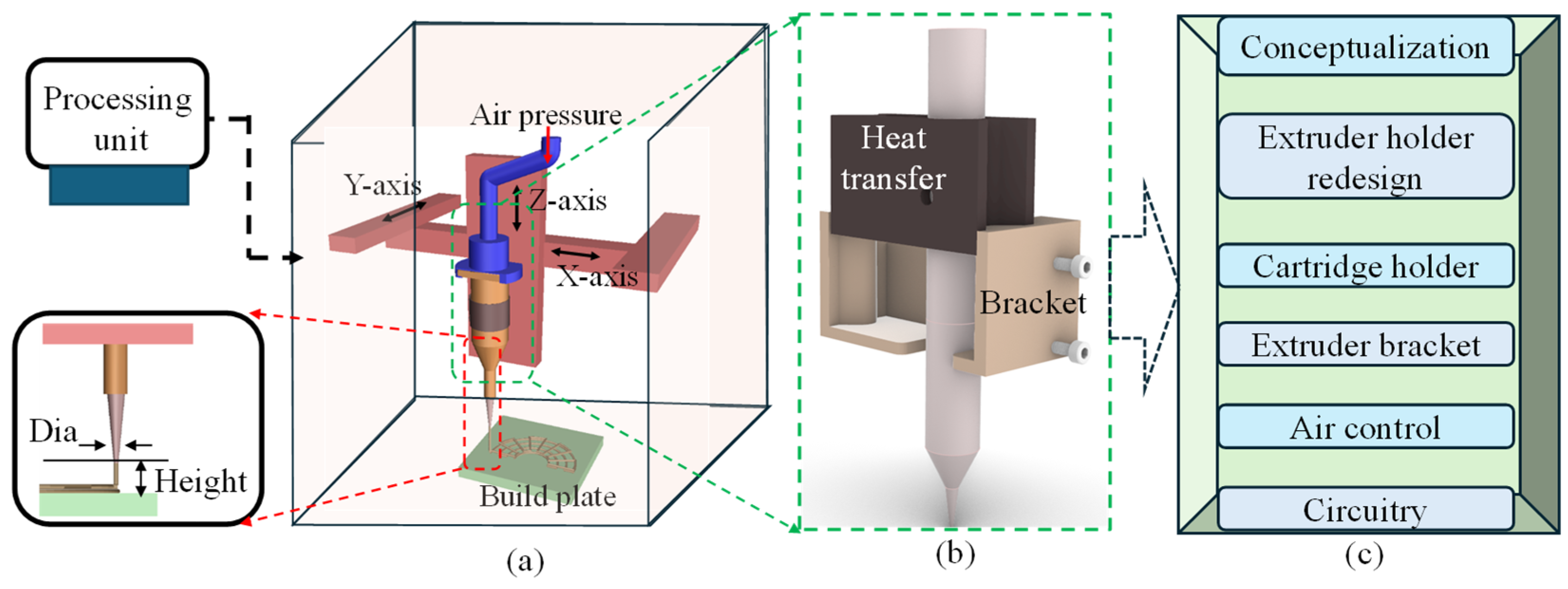
This section highlights the conceptualization of the proposed nozzle holder that will substitute the standard filament extruder of regular 3D printers with a specialized extruder head developed in-house for bioprinters, as shown in Figure 1. The modified extruder head consists of two main parts: a milled aluminum block and an extruder head bracket. The aluminum block facilitates heat transfer and shields the heating element from damage, while the 3D-printed resin bracket ensures precise alignment between the hydrogel container (e.g., dispensing syringe) and the heated clamp of the extruder head. This manufacturing approach guarantees precision and high heat resistance, minimizing errors. A series of operations such as extruder holder design, cartridge holder redesign, extruder bracket design, pneumatic design, and finally the circuitry design and development will be discussed in the following sections. These improvements collectively contribute to the optimization of the system’s performance and functionality.

Figure 1.
An overview of the nozzle holder design: (a) a schematic of the bioprinter with a processing unit and process parameters, (b) a concept proposition, and (c) a flow chart of related experiments to modify for the final design and development.
2.2. Replacement of Extruder
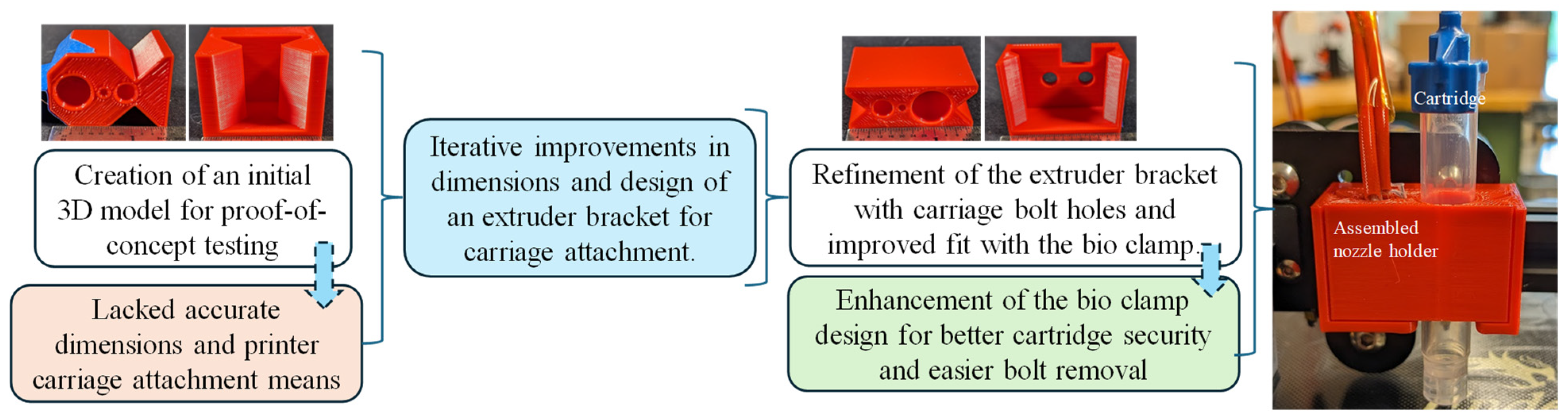
The development of the new extruder head involved multiple iterations, primarily focusing on securely attaching it to the 3D printer’s extruder carriage while maintaining proximity to the original filament extrusion point. The initial attempts to incorporate a syringe hole between the carriage bolt points proved impractical due to spacing issues. A two-part design concept was then explored, starting with a dovetail design proof of concept, which provided valuable insights into necessary tolerances and design flaws, as shown in Figure 2. It had inaccurate overall dimensions and lacked a means of attachment to the 3D printer motion system. Further refinement followed, incorporating holes for carriage bolts in the extruder bracket and improving the fit between the bio clamp and the extruder bracket. The bio clamp itself underwent improvement to better secure the bio-cartridge, introducing slots to facilitate easier bolt removal. Ultimately, efforts were made to bring the extrusion point closer to the printer’s original position and to streamline the manufacturing process, reducing the difficulty associated with the bio clamp. The initial and improved designs were printed using MakerBot Replicator by Ultimaker (Manhattan, NY, USA) with default settings to investigate the fitment with the printer and syringe, as shown in Figure 2.
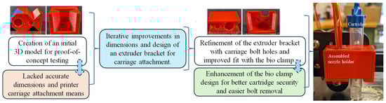
Figure 2.
Extruder head replacement from concept development to enhanced design.
2.3. The Design of the Extruder
2.3.1. Engineering Drawing of Extruder Bracket
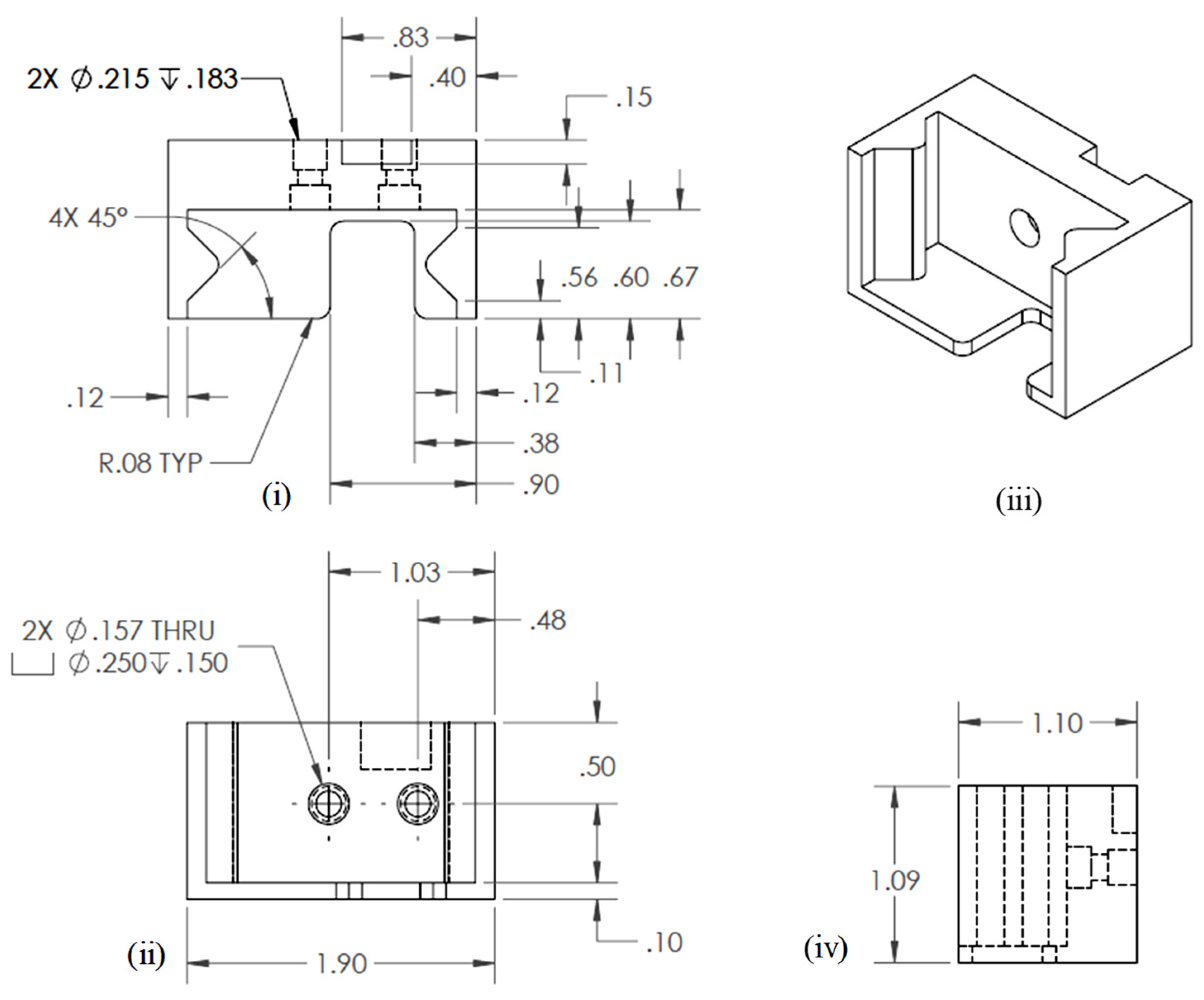
Three-dimensional modeling and simulation software, Solid Works v 2023 (Dassault Systèmes, Waltham, MA, USA), was used to develop engineering drawing. The final engineering drawing of the extruder bracket is shown in Figure 3.
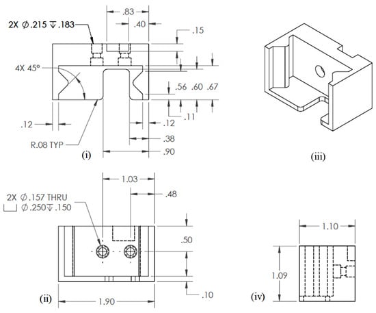
Figure 3.
Engineering drawing for extruder bracket: (i) Top view, (ii) Front view, (iii) Isometric view, and (iv) Side view.
2.3.2. Engineering Drawing of Syringe Holder and Assembly
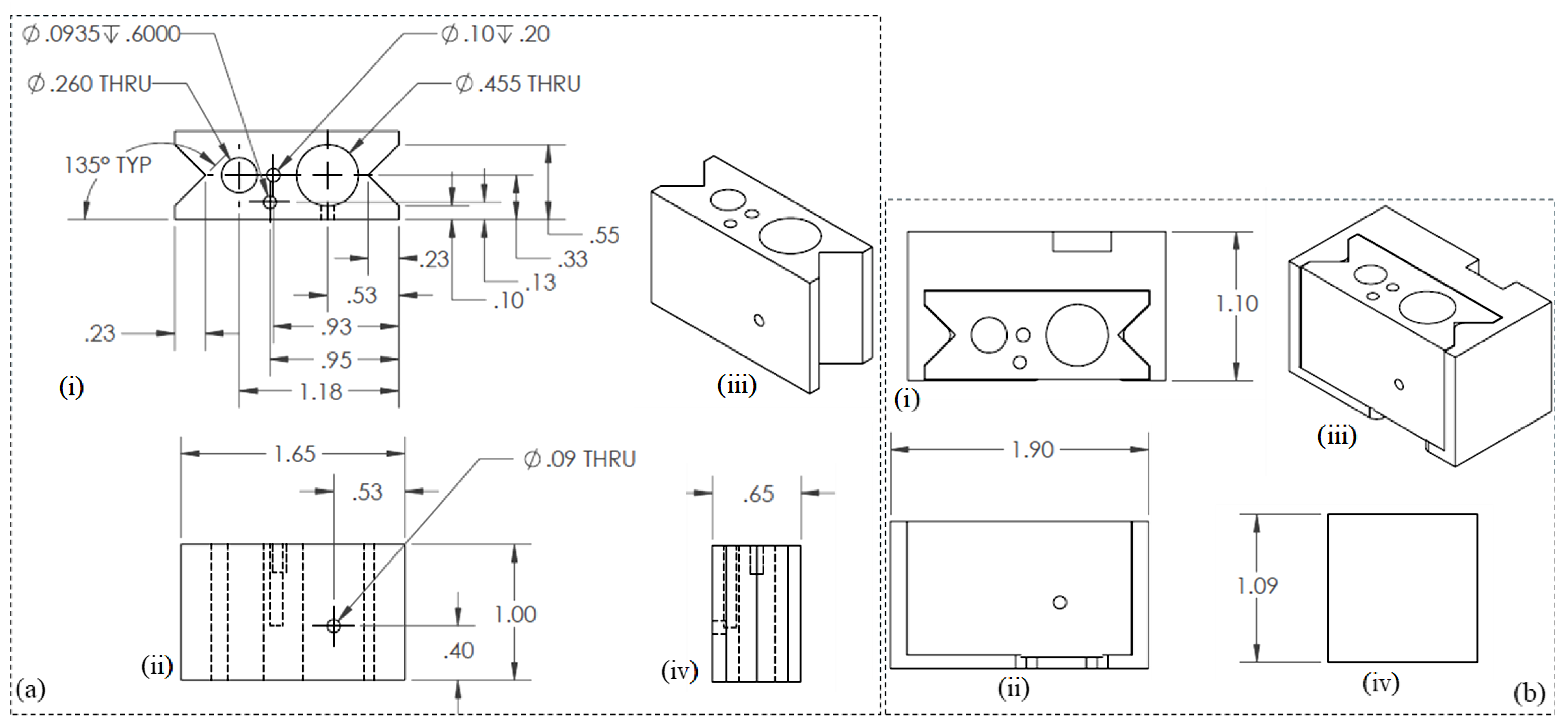
Similar 3D modeling and simulation software as mentioned in Section 2.3.1 was used to develop the engineering drawing. The final engineering drawings of the nozzle/syringe holder and overall assembly are shown in Figure 4a and Figure 4b, respectively.
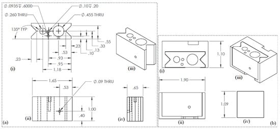
Figure 4.
Engineering drawings for (a) nozzle holder: (i) Top view, (ii) Front view, (iii) Isometric view, and (iv) Side view. and (b) nozzle syringe assembly: (i) Top view, (ii) Front view, (iii) Isometric view, and (iv) Side view.
2.4. The Manufacturing of the Extruder
2.4.1. Manufacturing of Syringe Holder
At the core of this innovation lies a precisely engineered aluminum block, milled to accommodate the heating element, heat sensor, and syringe. General-purpose Aluminum 6061 alloy was used for this fabrication. This design choice reflects a calculated approach to optimize thermal properties crucial for bio-ink preservation. The selection of milled aluminum for this component serves two key purposes: first, enhancing heat transfer efficiency and second, providing a protective shield against potential heating element damage. A Bridgeport milling machine (Bridgeport, CT, USA) was utilized for the machining process to achieve the desired dimensions. Moreover, rigorous controls were implemented to maintain a consistently low temperature within the bioprinting environment, safeguarding the bio-ink’s integrity. This integration of carefully engineered components resulted in an enhanced extrusion-based 3D bioprinter with the potential to transform tissue engineering practices.
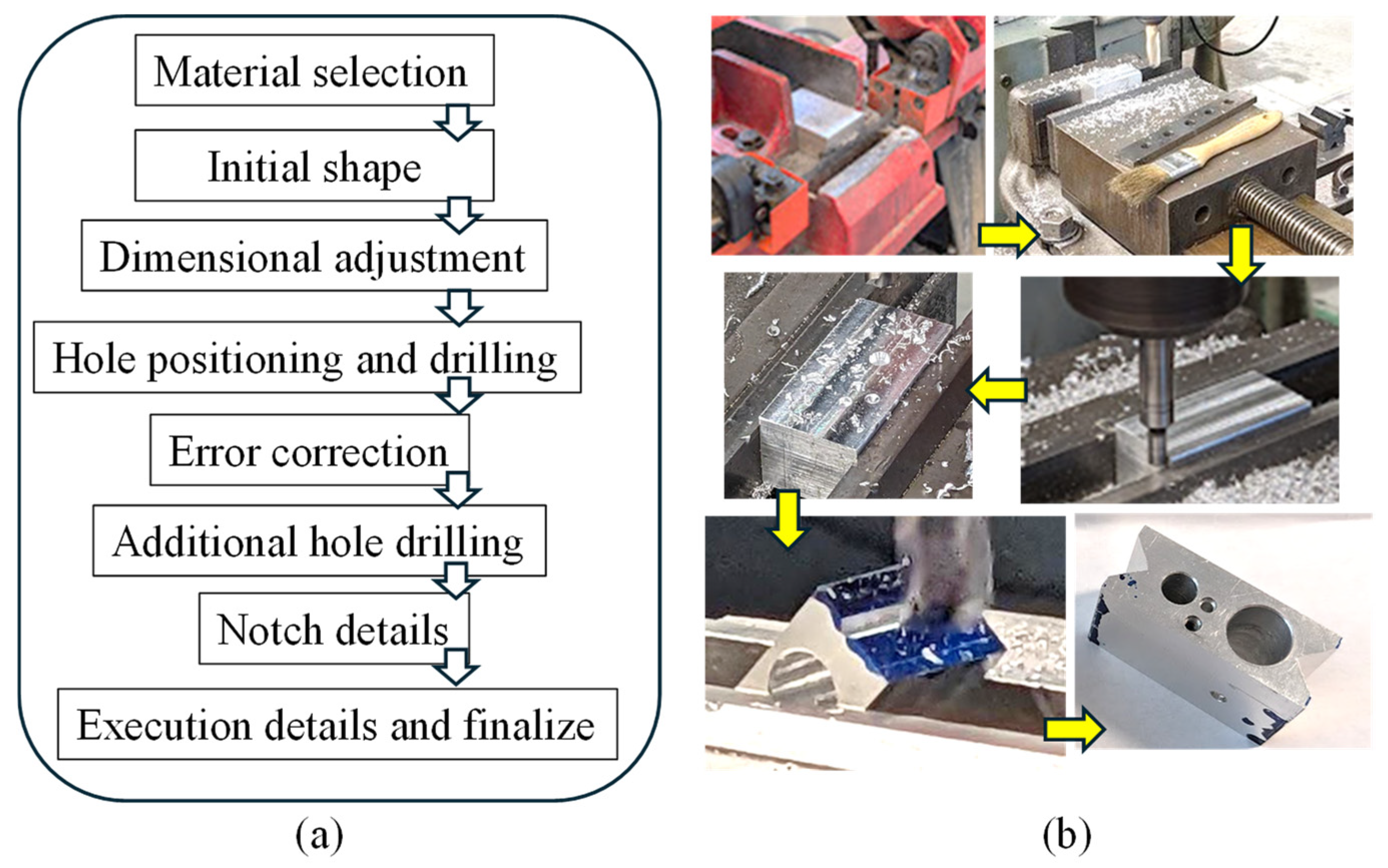
Figure 5a,b illustrate the planning and fabrication processes, respectively. The extruder head bracket demonstrates remarkable precision in connecting the 3D printer’s trunnion to the extruder head’s heated clamp. The choice of this manufacturing method is based on its established accuracy and relatively high heat resistance, effectively minimizing potential temperature-related inconsistencies.

Figure 5.
(a,b) Workflow to manufacture the nozzle holder from material selection to final product.
2.4.2. Manufacturing of Extruder Bracket and Assembly
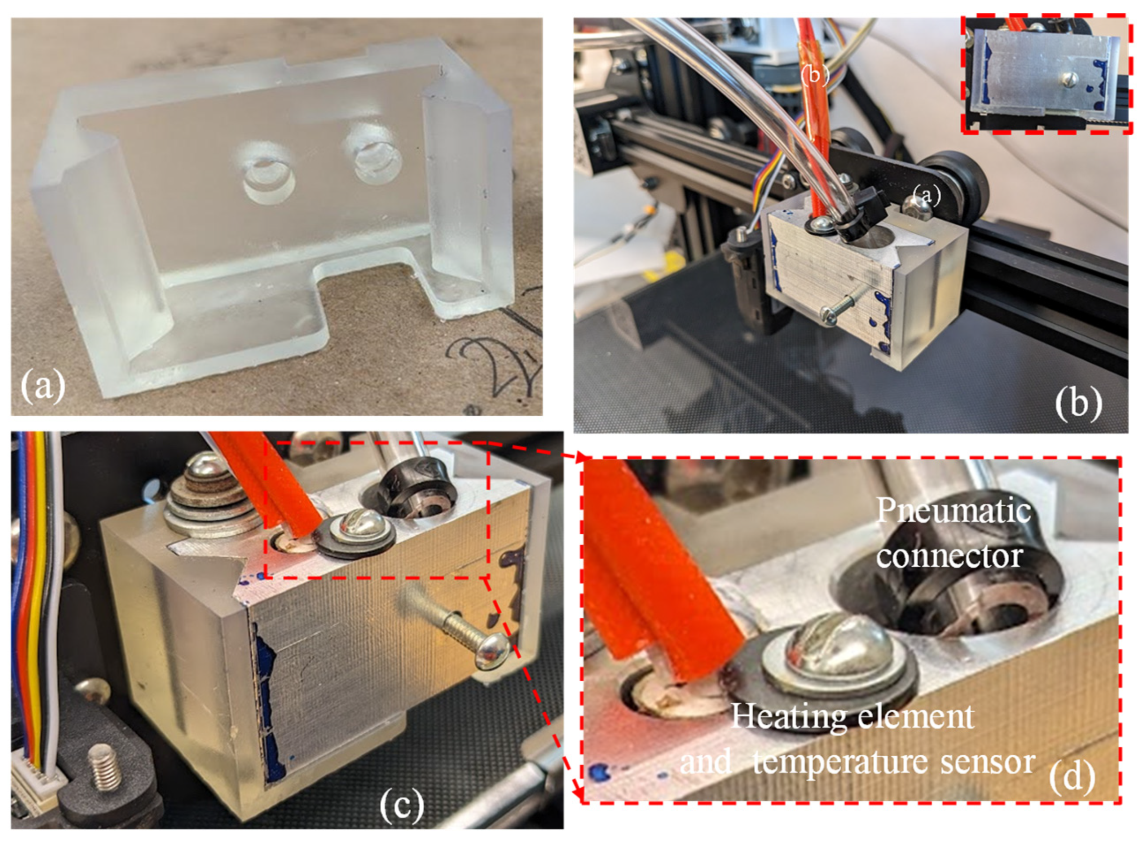
A crucial element in the improved extruder head assembly is the 3D-printed extruder head bracket, produced using a freeform resin printer (Form 3, Formlab, Somerville, MA, USA), as shown in Figure 6a. Once the bracket and nozzle holder were manufactured, they were assembled to demonstrate the fitment. Figure 6b,d show the pneumatic connector, heating element, and temperature sensor attachment to the assembled extruder. This showcases an exceptional accuracy in the interconnecting parts between the 3D printer’s trunnion and the heated clamp of the extruder head. The assembly’s components were fastened together using screws and washers. To maintain an appropriate temperature for the cells (around 37 °C), the printer’s original heating element and temperature sensor were reused.

Figure 6.
(a) Resin-printed extruder bracket; (b) assembly of aluminum syringe holder and resin bracket; (c,d) pneumatic connector, heating element, and temperature sensor.
2.4.3. Syringe Air Control for In-House Bio-Ink Printing Confirming Shape Fidelity and Viability
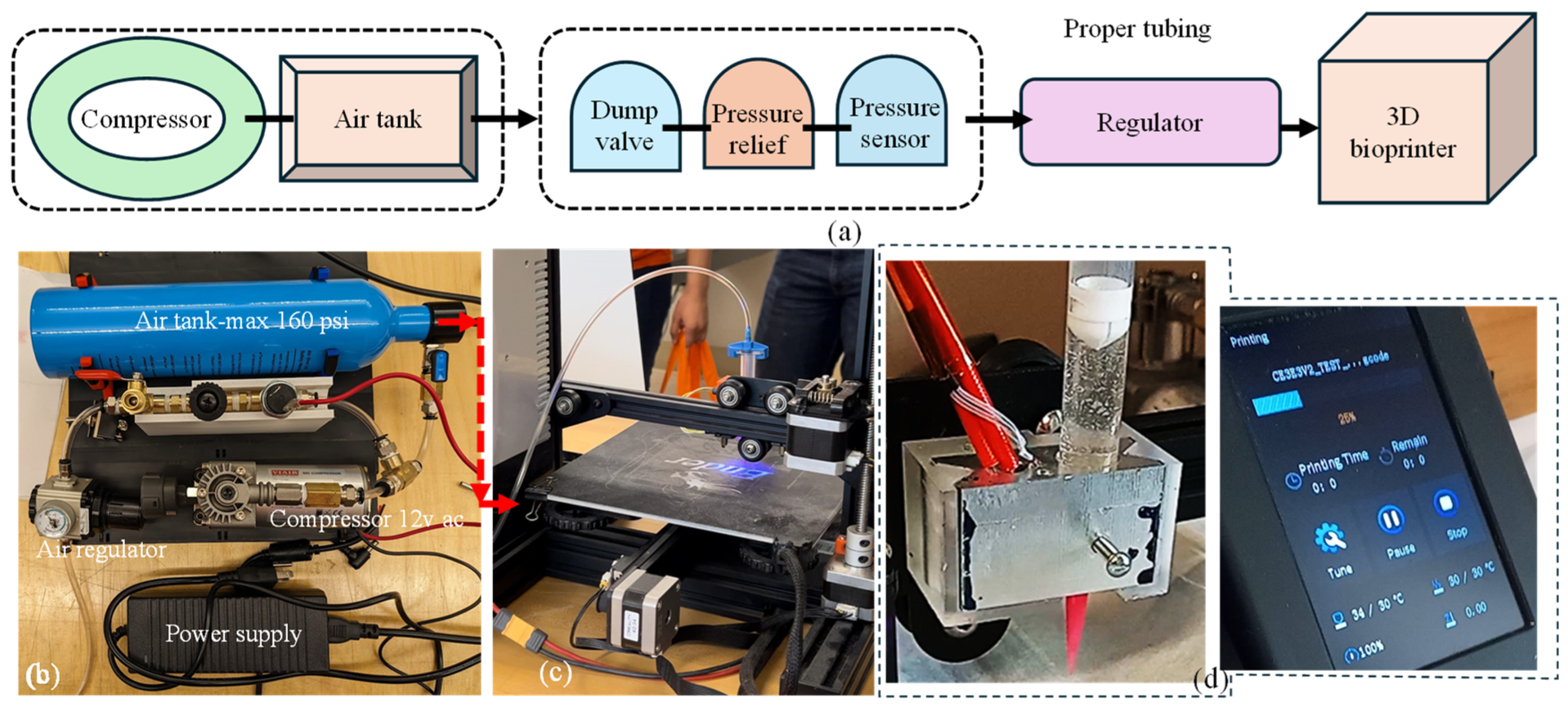
The decision to utilize pneumatic extrusion in this project underscores the importance of a well-designed air compressor system. This system is crucial for supplying the 3D bioprinter with the necessary compressed air at various pressure levels to extrude materials designed and developed in-house. The compressor setup was designed with portability, allowing for easy transportation alongside the 3D printer. Additionally, the required amount of air supply was confirmed to maintain a consistent pressure throughout the printing process. In our setup, the power source was passed through the pressure sensor switch. This switch was designed to deactivate the compressor when the pressure reaches 100 psi and reactivate it when it drops to a minimum amount governed by the material viscosity (e.g., pressure required for A4C4 [44] extrusion) to maintain a consistent flow. To complete the system loop, we connected the ground directly to the compressor ground. If the compressor does not turn on when plugged in, the user may need to switch the cables leading to the pressure switch. The occasional cable swaps can cause malfunctions that can be resolved by reconnecting them correctly. The specific connection method for the pneumatic tubing is not critical if it passes through the compressor safety system before reaching the pressure regulator. From the pressure regulator, the tubing extends to the 3D printer through the solenoids. Apart from this, the system is relatively straightforward, and if the current air tank is open, the setup should function smoothly. The entire connection setup is illustrated in Figure 7.
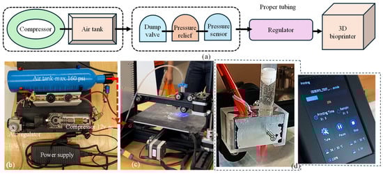
Figure 7.
(a) A schematic of all connections, (b) all components used to build air control systems and assembled air control systems, (c) assembled air control system connected to the customized nozzle holder, and (d) nozzle holder attached to the Ender 3 printer and working with our customized G-code.
2.4.4. Circuitry Design and Implementation
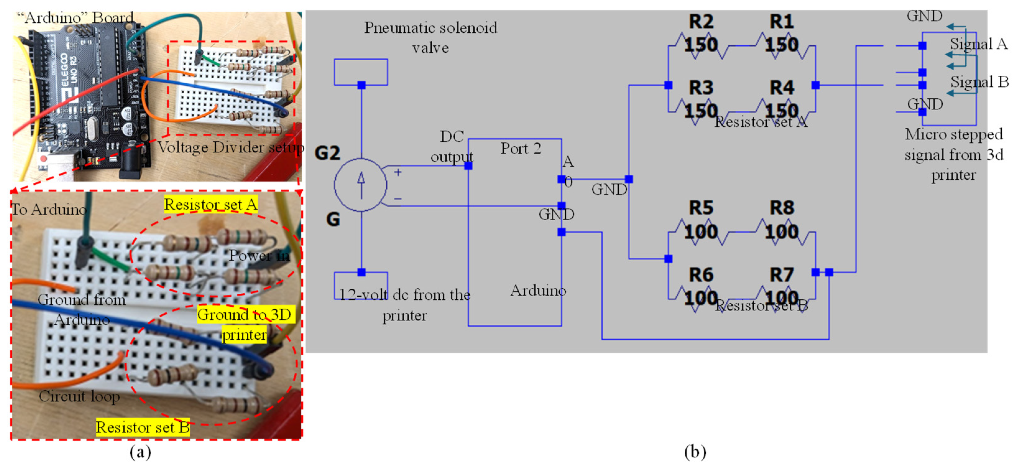
This section provides a brief overview of the wiring required for signal interpretation in this article, focusing on the connection between the Arduino and the voltage divider. It explains the voltage divider’s purpose and includes mathematical insights to facilitate potential adjustments or rewiring if necessary. The electrical path continues from the positive output to the terminal, entering the voltage divider’s resistor setup. Current flows through this setup, around to resistor setup B, and then returns to a ground cable via the other terminal for Signal A. The Arduino reads the voltage at the midpoint between resistor setups A and B. This midpoint positioning is crucial because the Arduino’s analog inputs are limited to 5 volts AC, while the signal output exceeds the standard 12 volts. The voltage divider’s primary function is to reduce the incoming 12 volts AC to below 5 volts AC. In this case, a 150-Ohm resistor setup is used for resistor A and a 100-Ohm resistor setup for resistor B. This configuration yields a 4.8-volt output, which is within the Arduino’s operational range. Figure 8a illustrates the connection between the Arduino and the voltage divider, including a detailed view of the voltage divider’s connection with the resistors. Figure 8b presents a comprehensive circuit diagram of the setup.
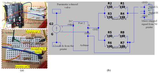
Figure 8.
(a) Connection between Arduino and voltage divider and detailed view of voltage divider connection with resistors and (b) circuit diagram generated using LTspice (Linear Technology, Milpitas, CA, USA).
3. Implementation and Application
3.1. Three-Dimensional Printing of Filaments and Construct with Proposed System
To demonstrate the implementation of our custom-made 3D printing system including a nozzle holder, circuitry design, air supply and control system, Arduino code, and G-code, our previously developed hybrid hydrogel composed with 4% alginate and 4% Carboxymethyl Cellulose [44] was used to extrude several filaments through a 410 µm nozzle, as shown in Figure 9a,b. A range of applied pressure from 10 to 15 psi along with 20–25 mm/s print speed was used. Toolpath was generated using in-house Arduino code integrated with slicer software. For this experimental test, we printed filaments at room temperature with the intention that the filament will maintain defined geometry after solidification. This system was able to extrude consistent and constant filaments successfully, as shown in Figure 9b. We did not observe significant difference in a set of three filaments we printed; to produce continuous filaments and consequently defined architectures of 3D-printed constructs, several process parameters need to be optimized such as extrusion pressure, nozzle diameter, printing speed and distance, and material composition and viscosities [45]. Extruded filaments showed ≤20% deviation compared to the nozzle diameter used. Maintaining this consistency is crucial to achieve defined porosities that affect cellular activities [46,47]. Having experience in solving a problem related to filament width and process parameters in our recently published article [26], our ongoing research will allow us to address these issues in the near future. Moreover, GelMA- and PEG-based photosensitive hybrid hydrogels are undergoing experiments to validate UV crosslinking. Related process parameters such as UV wavelengths (200–600 nm), the exposure time and sequence of LED on/off, the distance from LEDs to print beds, the choice of photosensitive polymers, and the type and amount of photo initiators will be optimized for continuous filaments and defined 3D constructs.
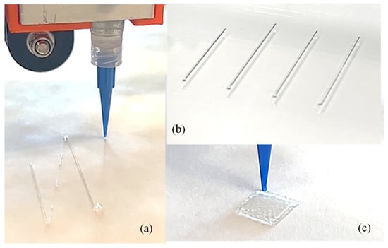
Figure 9.
(a) Extruding a single filament using our custom-made nozzle-holding system, (b) a series of printed filaments to show consistency, and (c) a 3D-printed construct. Additionally, 4% alginate and 4% CMC were used to print the filament and scaffold.
3.2. Application for Various Bio-Inks
To further apply our developed nozzle system in future, we will utilize a series of novel bio-inks such as alginate–Carboxymethyl Cellulose [44], alginate–Carboxymethyl Cellulose–Montmorillonite nano-clay [45], alginate–Carboxymethyl Cellulose–Tempo-Mediated nano-Fibrillated Cellulose (TONFC) [48], and pre-crosslinked alginate–Carboxymethyl Cellulose [49], these were developed in-house to achieve shape fidelity for clinically relevant scaffolds (up to 5 cm) and higher cell viability (≥80%). A range of applied pressure, e.g., 8–20 psi, was utilized for extruding these bio-inks. The process parameters (nozzle diameter, applied pressure, and print speed and distance) used for these bio-inks will be mimicked in the proposed system, and performance will be evaluated compared to the shape fidelity and cell viability of these bio-inks.
4. Attachment for Extrusion, Crosslinking, and UV Curing
4.1. Proposition of Attachments
To accommodate photo-crosslinking with ultraviolet (UV) light having user-defined wavelengths (with a range of 200–500 nm) and physical crosslinking (with the application of Ca2+) methods, three semi-modular attachments were designed to be compatible with the proposed nozzle holder, as shown in Figure 10. While the range of 200–250 nm can be harmful for cells [50], this range can be useful for acellular crosslinking. This module design will allow the 3D bioprinter to be equipped with any combination of these attachments, ranging from a simple attachment to a complex one. The choice of combination will depend on the specific materials (photo-crosslinking or chemical crosslinking), scale of scaffolds, and cell viability requirements.
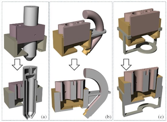
Figure 10.
Proposed 3D models for next step extruders: (a) syringe mount, (b) hose mount, and (c) UV light mount.
The first attachment, shown in Figure 10a, is an extrusion-based crosslinking attachment. This attachment allows for the use of a pneumatic system and solenoid, similar to that powering the syringe, to extrude the crosslinker out of a vessel surrounding the syringe, such that it combines with the hydrogel as it exits the orifice of the syringe. This allows for direct control over the amount of crosslinker that the hydrogel is receiving. However, this attachment requires a modification of the nozzle holder to account for the larger diameter of the syringe-surrounding assembly, with the size of both the aluminum cartridge holder and the resin block needing to be moderately increased. Figure 10b depicts a spray-based crosslinking nozzle attachment. Its design and functionality are similar to the first attachment, providing an alternative option for crosslinker application during the printing process. While the design proposed in Figure 10b can offer a higher crosslinking rate and quicker solidification after releasing from the nozzle, this can a create a nozzle clog if the wait time is not controlled properly for printing subsequent layers [51,52]. This challenge can be resolved by spraying, where the released hydrogel will be partially crosslinked and leave more time to complete subsequent printing without nozzle clogs [53]. This attachment is intended to be affixed to the side of the nozzle holder and contain a small tube and misting nozzle, such that the crosslinker can be sprayed onto the printed hydrogel either while it is extruding or during additional curing passes. This misting nozzle is held close to the end of the cartridge so that the crosslinker is misted onto the extruded hydrogel in a predictable manner. This misting attachment will use the same pneumatic system as the primary nozzle system, with a separate control method based on instructions sent to the same microcontroller. Finally, Figure 10c showcases a UV curing attachment. This device is designed to accommodate a UV LED light strip around its ring, which can be connected to a microcontroller for power regulation. The attachment secures to the existing nozzle holder block by snapping onto its upper four corners. This component is specifically intended for photo-active hydrogels, and alternative attachments would be necessary for curing other hydrogel types.
4.2. The 3D Printing of Attachments and Future Recommendations
To expand the practical implications in various biomedical applications, such as tissue engineering, regenerative medicine, and drug delivery systems, we can update the scalability of our bioprinter. One such addition is a dual crosslinking feature including physical (with CaCl2) and photo-crosslinking (with UV) [54]. While UV crosslinking can assist in holding the shape during printing, physical crosslinking will increase the overall shape fidelity after printing. Moreover, we will explore the pre-crosslinking technique to enhance scalability that we reported in our earlier research [49]. Controlling material preparation to be capable of dual or pre-crosslinking along with appropriate process parameter selection can allow users to create patient-specific implants or scaffolds for wound healing, which could significantly improve patient outcomes. Furthermore, based on the dimensions of the printer used to attach to our system, the scale can vary. Finally, we will consider the implications for commercial viability, including partnerships with healthcare providers and the integration of this technology into existing manufacturing processes, thereby showcasing its transformative potential in the field of biomanufacturing.
As proof of concept, we successfully 3D printed models of a syringe mount, hose mount, and UV light mount, as illustrated in Figure 11a, Figure 11b, and Figure 11c, respectively. Our future work will focus on several key areas of improvement and expansion:
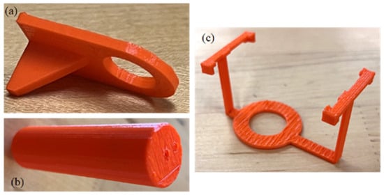
Figure 11.
Three-dimensional-printed models as proof of concept: (a) hose mount, (b) syringe mount, and (c) UV light mount.
- Enhancing attachment design for better stability and user-friendliness.
- Investigating alternative materials to improve durability and compatibility with various 3D printers.
- Developing a modular Multi-Attachment System for easy switching between curing methods.
- Creating plugins for popular 3D printing software to streamline printing and curing processes.
- Expanding microcontroller functionality to include real-time monitoring, feedback mechanisms, and smart device connectivity.
- Researching alternative UV light sources to optimize curing for specific hydrogel formulations.
- Collecting and incorporating user feedback from diverse fields to iteratively improve the UV curing attachment’s design and functionality.
These future developments aim to enhance the versatility, efficiency, and user experience of our 3D printing system for hydrogel-based applications.
5. Conclusions
In conclusion, this study not only signifies a significant advancement in bioprinting technology but also underscores the critical role of innovative engineering in overcoming the unique challenges inherent in tissue engineering. The adaptive nozzle system ensures the secure containment of the bio-ink, while the pneumatically driven plunger mechanism facilitates precise dispensing. The careful selection of materials and manufacturing techniques in the extruder head components highlights a commitment to safeguarding the bio-ink’s integrity and optimizing the system’s thermal performance. This research lays a solid foundation in the advancement of tissue engineering methodologies through cutting-edge bioprinting technology. The success of this project will help (i) explore novel bio-ink formulations with improved thermal stability and printability, (ii) develop multi-material printing strategies for complex tissue constructs, (iii) overcome compatibility issues with existing hardware and software, and (iv) resolve scalability concerns for large-scale production.
Author Contributions
A.H. conceived the idea. C.S. and S.C. created the preliminary design and fabrication. P.W. finalized the design and fabrication. All authors have read and agreed to the published version of the manuscript.
Funding
This research was supported by New Hampshire-EPSCoR through BioMade Award #1757371 from National Science Foundation, New Hampshire-INBRE through an Institutional Development Award (IDeA), P20GM103506, from the National Institute of General Medical and Sciences of the NIH. College of Engineering Technology, Rochester Institute of Technology.
Data Availability Statement
Data is contained within the article.
Acknowledgments
Department of Sustainable Product Design and Architecture, Keene State College, Keene, NH and Department of Manufacturing and Mechanical Engineering Technology of Rochester Institute of Technology.
Conflicts of Interest
The authors declare no conflicts of interest.
References
- Available online: https://www.organdonor.gov/learn/organ-donation-statistics (accessed on 15 June 2024).
- He, Y.; Yang, F.; Zhao, H.; Gao, Q.; Xia, B.; Fu, J. Research on the printability of hydrogels in 3D bioprinting. Sci. Rep. 2016, 6, 29977. [Google Scholar] [CrossRef] [PubMed]
- Atala, A.; Kasper, F.K.; Mikos, A.G. Engineering complex tissues. Sci. Transl. Med. 2012, 4, 160rv112. [Google Scholar] [CrossRef]
- Murphy, S.V.; Atala, A. 3D bioprinting of tissues and organs. Nat. Biotechnol. 2014, 32, 773–785. [Google Scholar] [CrossRef]
- Pichler, R.; Rizzo, L.; Tröndle, K.; Bühler, M.; Brucker, H.; Müller, A.-L.; Grand, K.; Farè, S.; Viau, A.; Kaminski, M.M. Tuning the 3D microenvironment of reprogrammed tubule cells enhances biomimetic modeling of polycystic kidney disease. Biomaterials 2022, 291, 121910. [Google Scholar] [CrossRef]
- Van Genderen, A.; Valverde, M.; Capendale, P.E.; Kersten, M.; Garví, E.S.; Schuurmans, C.C.; Ruelas, M.; Soeiro, J.T.; Tang, G.; Janssen, M.J. Co-axial printing of convoluted proximal tubule for kidney disease modeling. Biofabrication 2022, 14, 044102. [Google Scholar] [CrossRef] [PubMed]
- Fransen, M.F.; Addario, G.; Bouten, C.V.; Halary, F.; Moroni, L.; Mota, C. Bioprinting of kidney in vitro models: Cells, biomaterials, and manufacturing techniques. Essays Biochem. 2021, 65, 587–602. [Google Scholar] [PubMed]
- Rajalekshmi, R.; Shaji, A.K.; Joseph, R.; Bhatt, A. Scaffold for liver tissue engineering: Exploring the potential of fibrin incorporated alginate dialdehyde–gelatin hydrogel. Int. J. Biol. Macromol. 2021, 166, 999–1008. [Google Scholar] [CrossRef]
- Bhise, N.S.; Manoharan, V.; Massa, S.; Tamayol, A.; Ghaderi, M.; Miscuglio, M.; Lang, Q.; Zhang, Y.S.; Shin, S.R.; Calzone, G. A liver-on-a-chip platform with bioprinted hepatic spheroids. Biofabrication 2016, 8, 014101. [Google Scholar] [CrossRef]
- Maiullari, F.; Costantini, M.; Milan, M.; Pace, V.; Chirivì, M.; Maiullari, S.; Rainer, A.; Baci, D.; Marei, H.E.-S.; Seliktar, D.; et al. A multi-cellular 3D bioprinting approach for vascularized heart tissue engineering based on HUVECs and iPSC-derived cardiomyocytes. Sci. Rep. 2018, 8, 13532. [Google Scholar] [CrossRef]
- Chung, J.H.; Naficy, S.; Yue, Z.; Kapsa, R.; Quigley, A.; Moulton, S.E.; Wallace, G.G. Bio-ink properties and printability for extrusion printing living cells. Biomater. Sci. 2013, 1, 763–773. [Google Scholar] [CrossRef]
- Hsieh, C.-T.; Langrana, N.A. A system approach in extrusion-based multi-material CAD. In Proceedings of the Solid Freeform Fabrication Symposium, Austin, TX, USA, 6–8 August 2001; pp. 313–321. [Google Scholar]
- Sakai, S.; Yoshii, A.; Sakurai, S.; Horii, K.; Nagasuna, O. Silk fibroin nanofibers: A promising ink additive for extrusion three-dimensional bioprinting. Mater. Today Bio 2020, 8, 100078. [Google Scholar] [CrossRef] [PubMed]
- Quigley, C.; Limon, S.M.; Sarah, R.; Habib, A. Factorial Design of Experiment Method to Characterize Bioprinting Process Parameters to Obtain the Targeted Scaffold Porosity. 3D Print. Addit. Manuf. 2023. [Google Scholar] [CrossRef]
- Tashman, J.W.; Shiwarski, D.J.; Feinberg, A.W. Development of a high-performance open-source 3D bioprinter. Sci. Rep. 2022, 12, 22652. [Google Scholar] [CrossRef] [PubMed]
- Ovsianikov, A.; Yoo, J.; Mironov, V. 3D Printing and Biofabrication; Springer International Publishing: Berlin/Heidelberg, Germany, 2018. [Google Scholar]
- Chua, C.K.; Leong, K.F. 3D Printing and Additive Manufacturing: Principles and Applications (with Companion Media Pack)-of Rapid Prototyping; World Scientific Publishing Company: Singapore, 2014. [Google Scholar]
- Chua, C.K.; Yeong, W.Y. Bioprinting: Principles and Applications; World Scientific Publishing: Singapore, 2015. [Google Scholar]
- Available online: https://www.cellink.com/bioprinting/bio-x-3d-bioprinter/ (accessed on 1 June 2024).
- Gu, Z.; Fu, J.; Lin, H.; He, Y. Development of 3D bioprinting: From printing methods to biomedical applications. Asian J. Pharm. Sci. 2020, 15, 529–557. [Google Scholar] [CrossRef] [PubMed]
- Deneault, J.R.; Chang, J.; Myung, J.; Hooper, D.; Armstrong, A.; Pitt, M.; Maruyama, B. Toward autonomous additive manufacturing: Bayesian optimization on a 3D printer. MRS Bull. 2021, 46, 566–575. [Google Scholar] [CrossRef]
- Ioannidis, K.; Danalatos, R.I.; Champeris Tsaniras, S.; Kaplani, K.; Lokka, G.; Kanellou, A.; Papachristou, D.J.; Bokias, G.; Lygerou, Z.; Taraviras, S. A custom ultra-low-cost 3D bioprinter supports cell growth and differentiation. Front. Bioeng. Biotechnol. 2020, 8, 580889. [Google Scholar] [CrossRef]
- Yilmaz, B.; Al Rashid, A.; Mou, Y.A.; Evis, Z.; Koç, M. Bioprinting: A review of processes, materials and applications. Bioprinting 2021, 23, e00148. [Google Scholar] [CrossRef]
- Zhang, T.; Zhao, W.; Xiahou, Z.; Wang, X.; Zhang, K.; Yin, J. Bioink design for extrusion-based bioprinting. Appl. Mater. Today 2021, 25, 101227. [Google Scholar] [CrossRef]
- Mironov, V.; Kasyanov, V.; Drake, C.; Markwald, R.R. Organ printing: Promises and challenges. Regen. Med. 2008, 3, 93–103. [Google Scholar] [CrossRef]
- Gungor-Ozkerim, P.S.; Inci, I.; Zhang, Y.S.; Khademhosseini, A.; Dokmeci, M.R. Bioinks for 3D bioprinting: An overview. Biomater. Sci. 2018, 6, 915–946. [Google Scholar] [CrossRef]
- Ozbolat, V.; Dey, M.; Ayan, B.; Povilianskas, A.; Demirel, M.C.; Ozbolat, I. 3D Printing of PDMS Improves its Mechanical and Cell Adhesion Properties. ACS Biomater. Sci. Eng. 2017, 4, 682–693. [Google Scholar] [CrossRef]
- Dubbin, K.; Tabet, A.; Heilshorn, S.C. Quantitative criteria to benchmark new and existing bio-inks for cell compatibility. Biofabrication 2017, 9, 044102. [Google Scholar] [CrossRef]
- Wang, F.; Tankus, E.B.; Santarella, F.; Rohr, N.; Sharma, N.; Märtin, S.; Michalscheck, M.; Maintz, M.; Cao, S.; Thieringer, F.M. Fabrication and Characterization of PCL/HA Filament as a 3D Printing Material Using Thermal Extrusion Technology for Bone Tissue Engineering. Polymers 2022, 14, 669. [Google Scholar] [CrossRef] [PubMed]
- Jang, C.H.; Ahn, S.H.; Yang, G.-H.; Kim, G.H. A MSCs-laden polycaprolactone/collagen scaffold for bone tissue regeneration. RSC Adv. 2016, 6, 6259–6265. [Google Scholar] [CrossRef]
- Nadernezhad, A.; Khani, N.; Skvortsov, G.A.; Toprakhisar, B.; Bakirci, E.; Menceloglu, Y.; Unal, S.; Koc, B. Multifunctional 3D printing of heterogeneous hydrogel structures. Sci. Rep. 2016, 6, 33178. [Google Scholar] [CrossRef] [PubMed]
- Tariq, A.; Arif, Z.U.; Khalid, M.Y.; Hossain, M.; Rasool, P.I.; Umer, R.; Ramakrishna, S. Recent advances in the additive manufacturing of stimuli-responsive soft polymers. Adv. Eng. Mater. 2023, 25, 2301074. [Google Scholar] [CrossRef]
- Sbirkov, Y.; Redzheb, M.; Forraz, N.; McGuckin, C.; Sarafian, V. High Hopes for the Biofabrication of Articular Cartilage—What Lies beyond the Horizon of Tissue Engineering and 3D Bioprinting? Biomedicines 2024, 12, 665. [Google Scholar] [CrossRef]
- Chae, S.; Ha, D.-H.; Lee, H. 3D bioprinting strategy for engineering vascularized tissue models. Int. J. Bioprint. 2023, 9, 748. [Google Scholar] [CrossRef]
- Choudhury, D.; Anand, S.; Naing, M.W. The arrival of commercial bioprinters–Towards 3D bioprinting revolution! Int. J. Bioprint. 2018, 4, 139. [Google Scholar] [CrossRef]
- Abdulmaged, A.I.; Soon, C.F.; Talip, B.A.; Zamhuri, S.A.A.; Mostafa, S.A.; Zhou, W. Characterization of alginate–gelatin–cholesteryl ester liquid crystals bioinks for extrusion bioprinting of tissue engineering Scaffolds. Polymers 2022, 14, 1021. [Google Scholar] [CrossRef]
- Quigley, C.; Sarah, R.; Hurd, W.; Clark, S.; Habib, M. Design and Fabrication of In-house Nozzle System to Extrude Multi-Hydrogels for 3D Bioprinting Process. J. Manuf. Sci. Eng. 2023, 146, 021003. [Google Scholar]
- Derakhshanfar, S.; Mbeleck, R.; Xu, K.; Zhang, X.; Zhong, W.; Xing, M. 3D bioprinting for biomedical devices and tissue engineering: A review of recent trends and advances. Bioact. Mater. 2018, 3, 144–156. [Google Scholar] [CrossRef] [PubMed]
- Falcone, G.; Mazzei, P.; Piccolo, A.; Esposito, T.; Mencherini, T.; Aquino, R.P.; Del Gaudio, P.; Russo, P. Advanced printable hydrogels from pre-crosslinked alginate as a new tool in semi solid extrusion 3D printing process. Carbohydr. Polym. 2021, 276, 118746. [Google Scholar] [CrossRef] [PubMed]
- Diamantides, N.; Wang, L.; Pruiksma, T.; Siemiatkoski, J.; Dugopolski, C.; Shortkroff, S.; Kennedy, S.; Bonassar, L.J. Correlating rheological properties and printability of collagen bioinks: The effects of riboflavin photocrosslinking and pH. Biofabrication 2017, 9, 034102. [Google Scholar] [CrossRef]
- Mouser, V.H.; Melchels, F.P.; Visser, J.; Dhert, W.J.; Gawlitta, D.; Malda, J. Yield stress determines bioprintability of hydrogels based on gelatin-methacryloyl and gellan gum for cartilage bioprinting. Biofabrication 2016, 8, 035003. [Google Scholar] [CrossRef]
- Kolesky, D.B.; Homan, K.A.; Skylar-Scott, M.A.; Lewis, J.A. Three-dimensional bioprinting of thick vascularized tissues. Proc. Natl. Acad. Sci. USA 2016, 113, 3179–3184. [Google Scholar] [CrossRef]
- Cidonio, G.; Glinka, M.; Dawson, J.; Oreffo, R. The cell in the ink: Improving biofabrication by printing stem cells for skeletal regenerative medicine. Biomaterials 2019, 209, 10–24. [Google Scholar] [CrossRef]
- Habib, A.; Sathish, V.; Mallik, S.; Khoda, B. 3D printability of alginate-carboxymethyl cellulose hydrogel. Materials 2018, 11, 454. [Google Scholar] [CrossRef] [PubMed]
- Habib, A.; Khoda, B. Development of clay based novel hybrid bio-ink for 3D bio-printing process. J. Manuf. Process. 2019, 38, 76–87. [Google Scholar] [CrossRef]
- Habib, M.; Khoda, B. Fiber Filled Hybrid Hydrogel for Bio-Manufacturing. J. Manuf. Sci. Eng. 2020, 143, 041013. [Google Scholar] [CrossRef]
- Nelson, C.; Tuladhar, S.; Launen, L.; Habib, M. 3D Bio-Printability of Hybrid Pre-Crosslinked Hydrogels. Int. J. Mol. Sci. 2021, 22, 13481. [Google Scholar] [CrossRef]
- Ozbolat, I.T.; Hospodiuk, M. Current advances and future perspectives in extrusion-based bioprinting. Biomaterials 2016, 76, 321–343. [Google Scholar] [CrossRef]
- Heo, D.N.; Alioglu, M.A.; Wu, Y.; Ozbolat, V.; Ayan, B.; Dey, M.; Kang, Y.; Ozbolat, I.T. 3D bioprinting of carbohydrazide-modified gelatin into microparticle-suspended oxidized alginate for the fabrication of complex-shaped tissue constructs. ACS Appl. Mater. Interfaces 2020, 12, 20295–20306. [Google Scholar] [CrossRef]
- Masuma, R.; Kashima, S.; Kurasaki, M.; Okuno, T. Effects of UV wavelength on cell damages caused by UV irradiation in PC12 cells. J. Photochem. Photobiol. B Biol. 2013, 125, 202–208. [Google Scholar] [CrossRef]
- Stanco, D.; Urbán, P.; Tirendi, S.; Ciardelli, G.; Barrero, J. 3D bioprinting for orthopaedic applications: Current advances, challenges and regulatory considerations. Bioprinting 2020, 20, e00103. [Google Scholar] [CrossRef]
- Park, W.; Gao, G.; Cho, D.-W. Tissue-specific decellularized extracellular matrix bioinks for musculoskeletal tissue regeneration and modeling using 3D bioprinting technology. Int. J. Mol. Sci. 2021, 22, 7837. [Google Scholar] [CrossRef]
- GhavamiNejad, A.; Ashammakhi, N.; Wu, X.Y.; Khademhosseini, A. Crosslinking strategies for 3D bioprinting of polymeric hydrogels. Small 2020, 16, 2002931. [Google Scholar] [CrossRef]
- Zhang, M.; Vora, A.; Han, W.; Wojtecki, R.J.; Maune, H.; Le, A.B.; Thompson, L.E.; McClelland, G.M.; Ribet, F.; Engler, A.C. Dual-responsive hydrogels for direct-write 3D printing. Macromolecules 2015, 48, 6482–6488. [Google Scholar]


Disclaimer/Publisher’s Note: The statements, opinions and data contained in all publications are solely those of the individual author(s) and contributor(s) and not of MDPI and/or the editor(s). MDPI and/or the editor(s) disclaim responsibility for any injury to people or property resulting from any ideas, methods, instructions or products referred to in the content. |
© 2024 by the authors. Licensee MDPI, Basel, Switzerland. This article is an open access article distributed under the terms and conditions of the Creative Commons Attribution (CC BY) license (https://creativecommons.org/licenses/by/4.0/).