
Guidelines for Design and Additive Manufacturing Specify the Use of Surgical Templates with Improved Accuracy Using the Masked Stereolithography Technique in the Zygomatic Bone Region


Abstract
1. Introduction
2. Materials and Methods
- Scan type: helical;
- Beam collimation: 40 mm;
- Detector configuration: 64 × 0.625 mm;
- Tube settings: 120 kV;
- Slice thickness: 1.25 mm;
- Matrix size: 512 × 512.
2.1. Process of Digital Processing, Segmentation, and 3D Reconstruction of DICOM Data
- The surface is smoothed by moving the nodes on which the triangle mesh is spanned. Each node is moved to the average position of its neighbors by applying the Laplace function. The function is the sum of the squares of the lengths of edges sharing a common node (2):
- k is the number of neighboring nodes; the position of new nodes is determined using Formula (3):
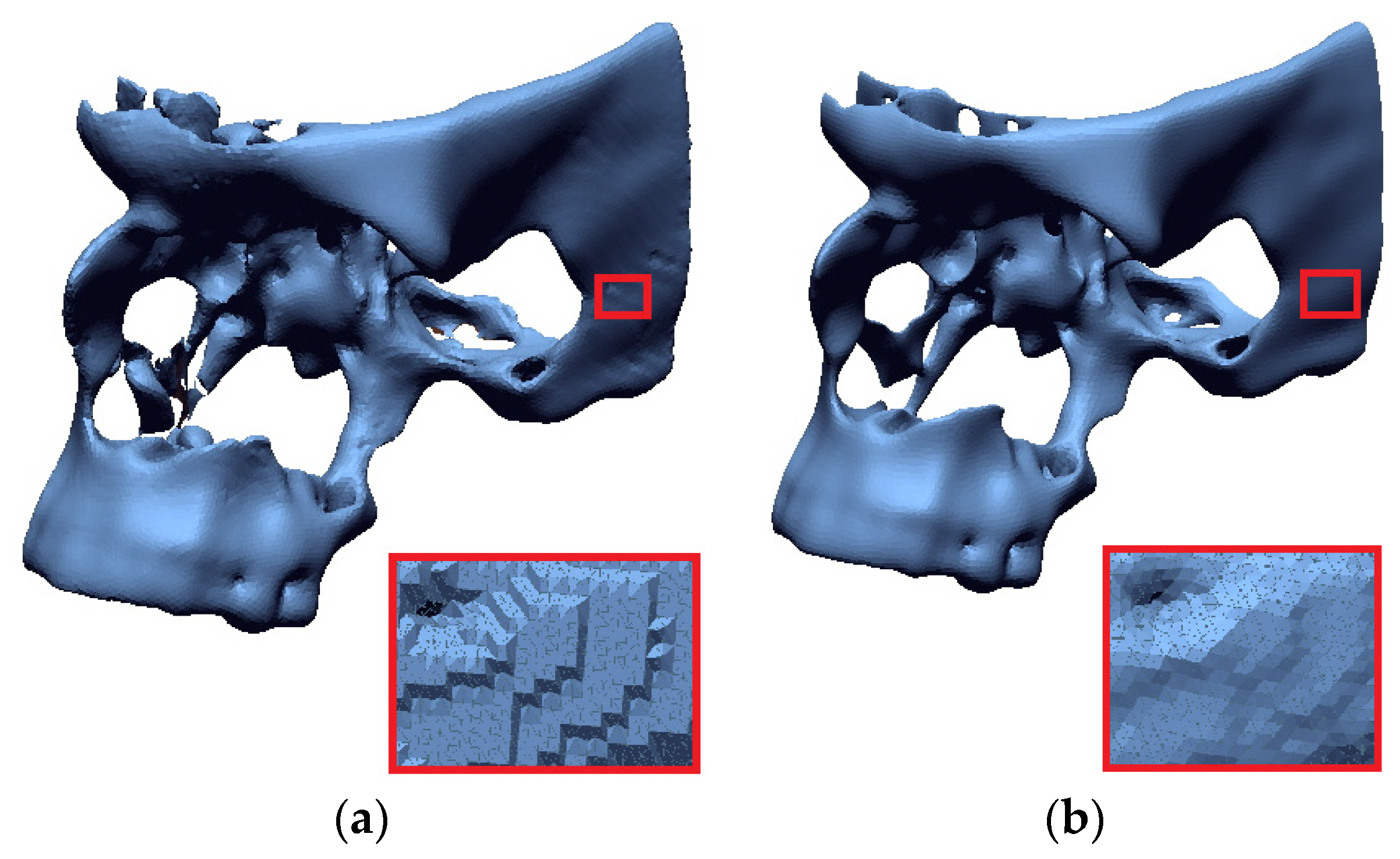
- Triangle densities are created in regions of high complexity, and reducing the number of triangles in flatter areas using the isotropic surface remashing algorithm.
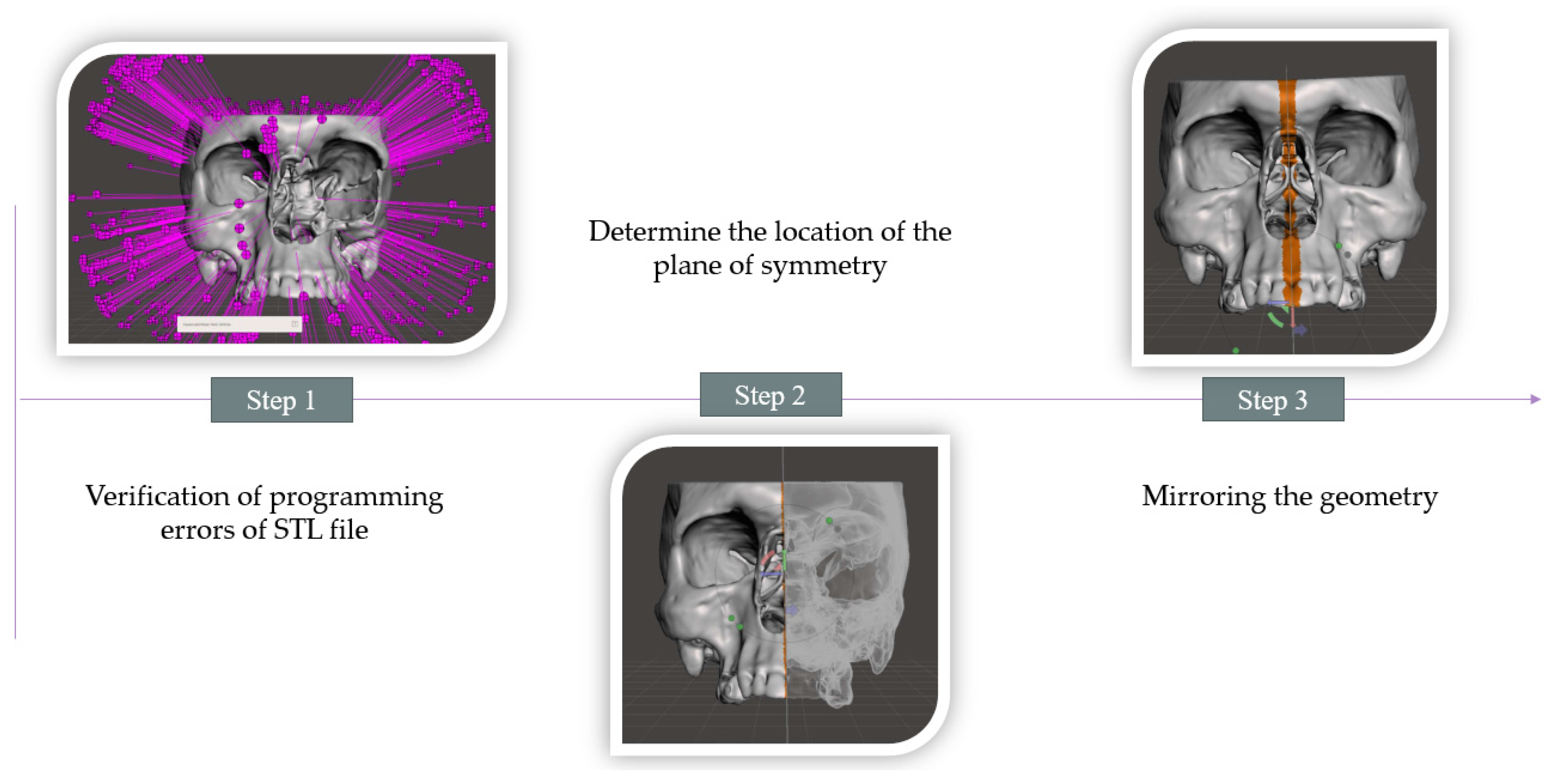
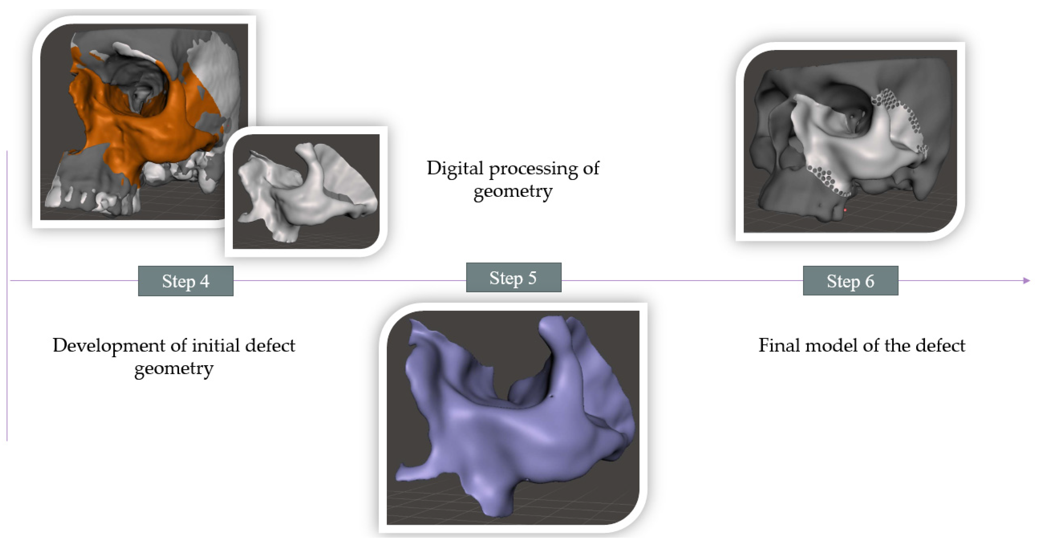
2.2. Procedure for Modeling a Defect in the Zygomatic Bone Area
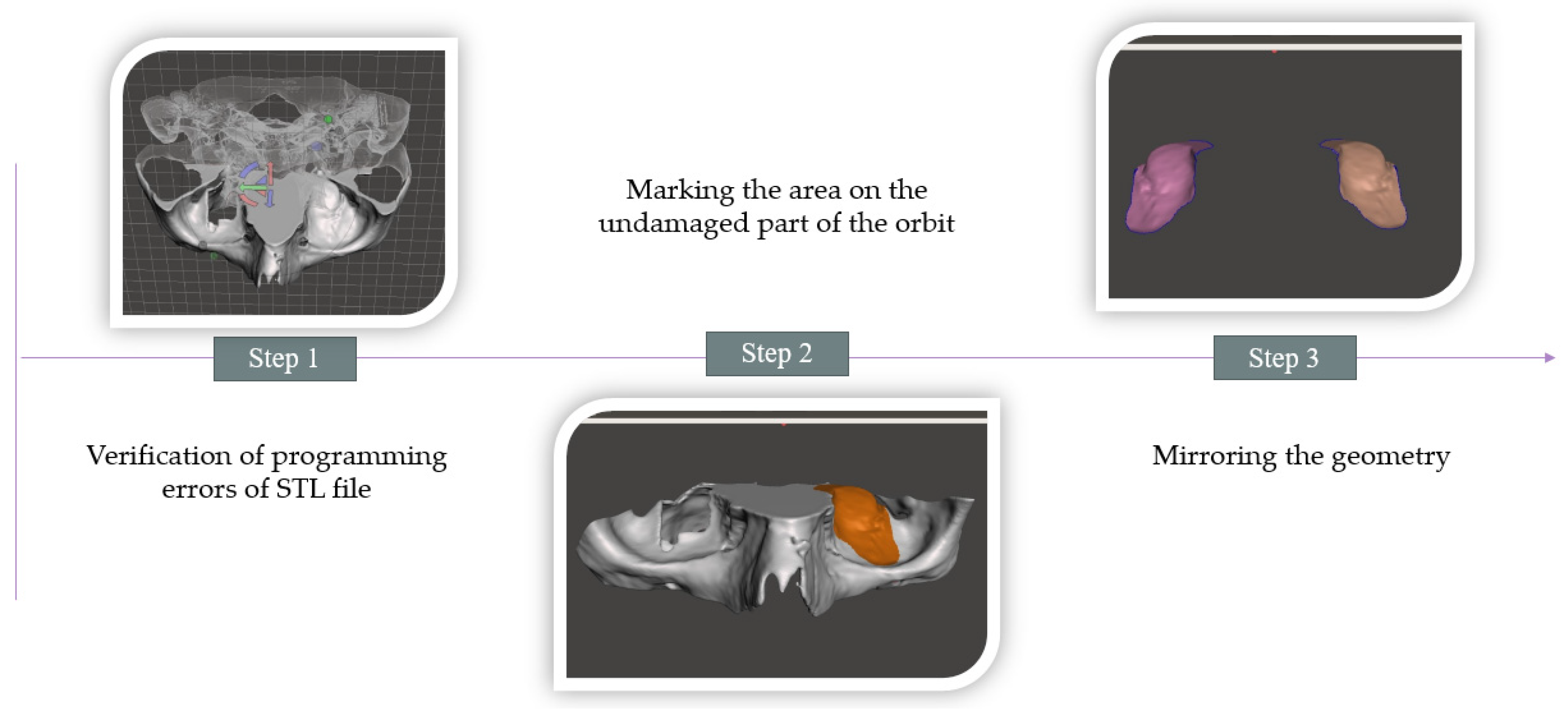
2.3. Development of a Tool to Form the Geometry of a Mesh Implant to Reconstruct an Orbital Floor Defect
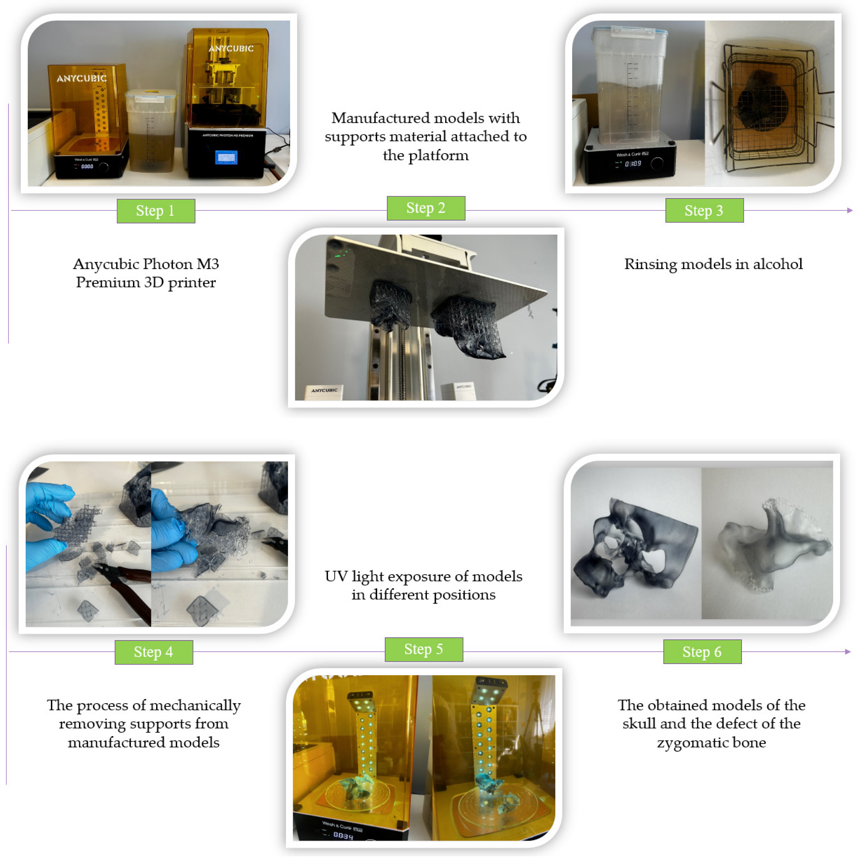
2.4. Additive Manufacturing of Designed Models Using the mSLA Method
3. Results
4. Discussion
4.1. Methods to Improve Accuracy in the Numerical Processing of DICOM Data
4.2. Methods to Improve Accuracy in the Numerical Processing of 3D-STL Models
4.3. Research on Assessing the Accuracy of Models Produced via mSLA Additive Manufacturing
5. Conclusions
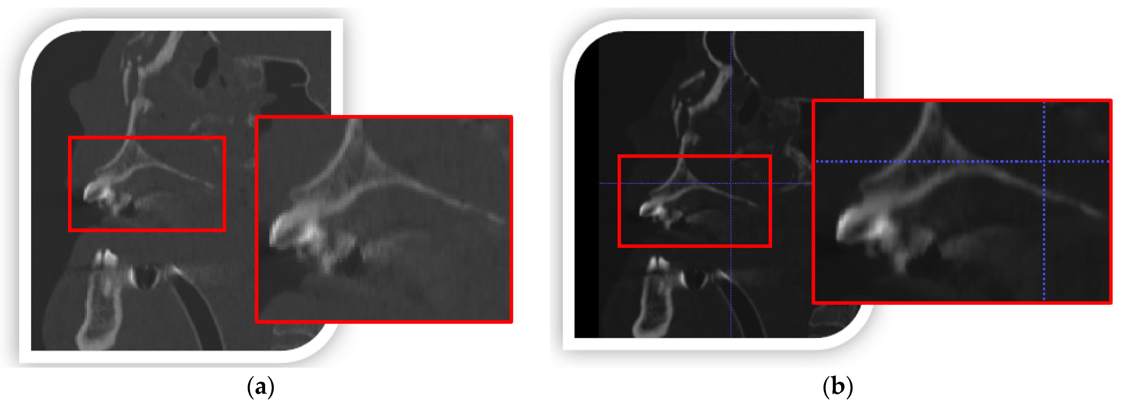
- DICOM data-processing increased spatial and contrast resolution by using a data interpolation process. In addition, the segmentation process used a local thresholding method, which more precisely determined the lower threshold for segmenting bone structures within the zygomatic bone area. Through the use of remeshing methods, the quality of the facet area was significantly increased,
- During CAD modeling, special attention was paid to tessellation, that is, converting the model from CAD to STL format. The values of chordal and angular deviation were adjusted so that errors made during data export were not duplicated in the process of manufacturing the model using the additive method,
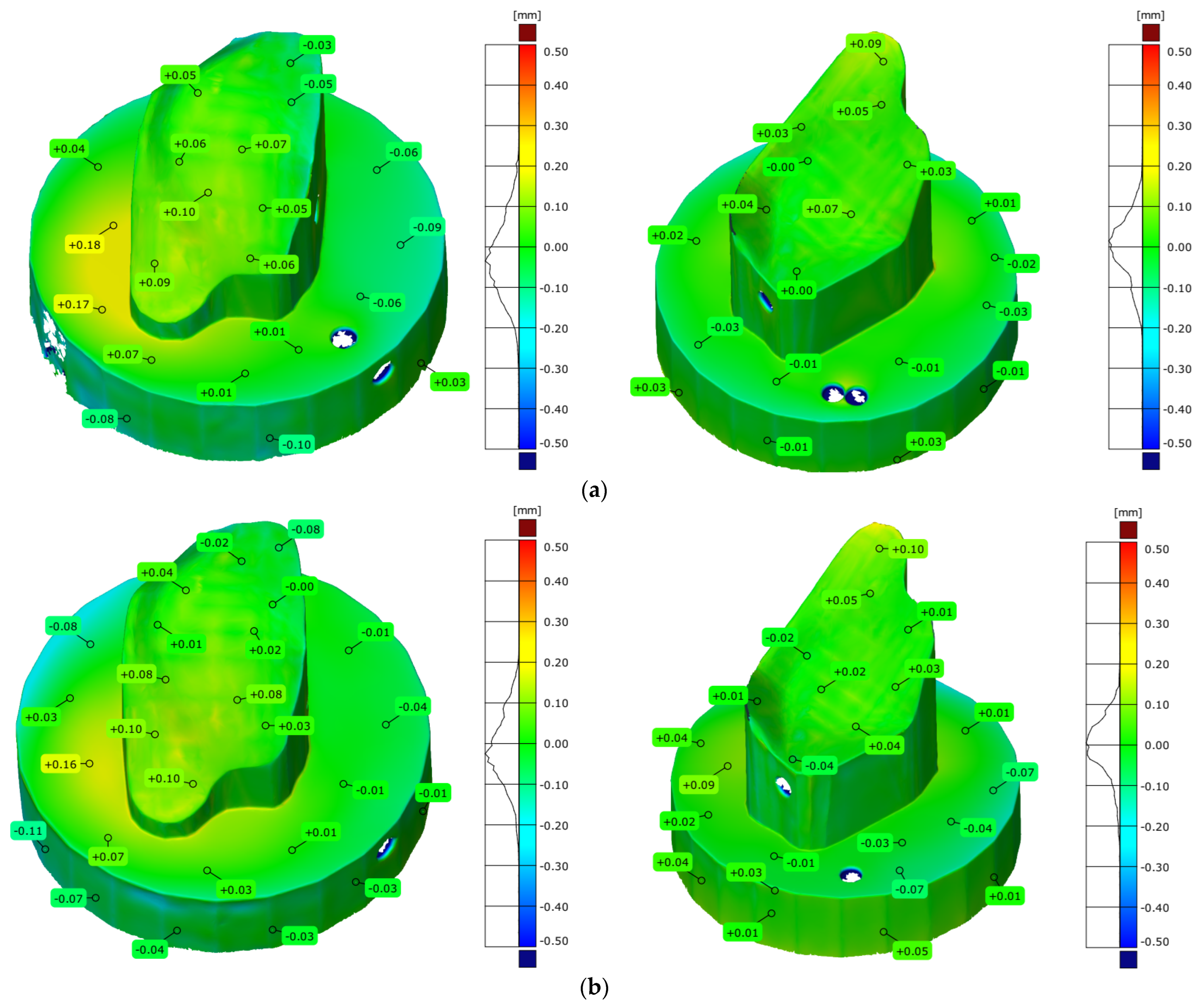
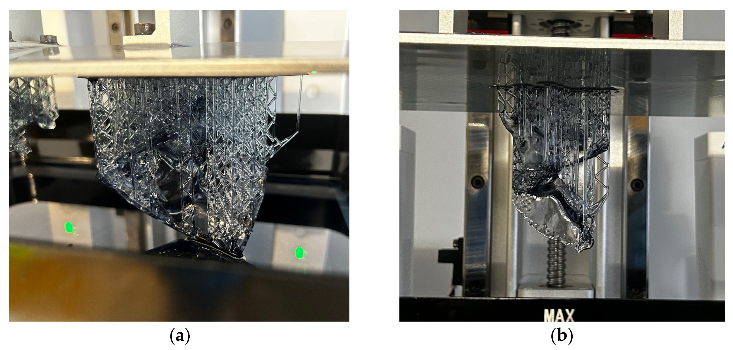
- The thinnest layer thickness used in the mSLA method was applied during manufacturing. The recommended model orientation within the 3D printer’s workspace was also utilized. The study evaluated two methods for generating the support material. The results indicated that the ultra-light mode produced a more accurate geometrical model. This was attributed to the reduced amount of support material generated during the model’s execution, which made the mechanical removal of supports easier during the post-processing stage.
Author Contributions
Funding
Data Availability Statement
Conflicts of Interest
References
- Cortese, A.; Caggiano, M.; Carlino, F.; Pantaleo, G. Zygomatic fractures: Technical modifications for better aesthetic and functional results in older patients. Int. J. Surg. 2016, 33, S9–S15. [Google Scholar] [CrossRef] [PubMed]
- Dechow, P.C.; Wang, Q. Development, structure, and function of the zygomatic bones: What is new and why do we care? Anat. Rec. 2016, 299, 1611–1615. [Google Scholar] [CrossRef] [PubMed]
- Modabber, A.; Rana, M.; Ghassemi, A.; Gerressen, M.; Gellrich, N.C.; Hölzle, F.; Rana, M. Three-dimensional evaluation of postoperative swelling in treatment of zygomatic bone fractures using two different cooling therapy methods: A randomized, observer-blind, prospective study. Trials 2013, 14, 238. [Google Scholar] [CrossRef]
- Markiewicz, M.R.; Gelesko, S.; Bell, R.B. Zygoma reconstruction. Oral Maxillofac. Surg. Clin. 2013, 25, 167–201. [Google Scholar] [CrossRef]
- Litschel, R.; Suárez, G.A. Management of zygomatic fractures: Bone and arch. Facial Plast. Surg. 2015, 31, 368–375. [Google Scholar] [CrossRef]
- Reiss, S.; Kulker, D.; Laure, B.; Paré, A. Reconstruction of the orbitozygomatic framework: State of the art and perspectives. J. Stomatol. Oral Maxillofac. Surg. 2024, 125, 101788. [Google Scholar] [CrossRef]
- Karalashvili, L.; Chichua, N.; Menabde, G.; Atskvereli, L.; Grdzelidze, T.; Machavariani, A.; Chichua, Z. Decellularized bovine bone graft for zygomatic bone reconstruction. Med. Case Rep. 2017, 4, 10–21767. [Google Scholar] [CrossRef]
- Zhu, Z.C.; Yang, Y.F.; Yang, X.; Liu, Y.; Cheng, Y.N.; Sun, Z.Y.; Yang, W.J. Treatment of cryotherapy and orthotopic transplantation following chondromyxoid fibroma of zygomatic bone: A case report. Medicine 2018, 97, e11707. [Google Scholar] [CrossRef]
- Sakkas, A.; Schramm, A.; Karsten, W.; Gellrich, N.C.; Wilde, F. A clinical study of the outcomes and complications associated with zygomatic buttress block bone graft for limited preimplant augmentation procedures. J. Cranio-Maxillofac. Surg. 2016, 44, 249–256. [Google Scholar] [CrossRef]
- Costan, V.V.; Nicolau, A.; Sulea, D.; Ciofu, M.L.; Boișteanu, O.; Popescu, E. The impact of 3D technology in optimizing midface fracture treatment—Focus on the zygomatic bone. J. Oral Maxillofac. Surg. 2021, 79, 880–891. [Google Scholar] [CrossRef]
- Lee, U.L.; Lim, J.Y.; Park, S.N.; Choi, B.H.; Kang, H.; Choi, W.C. A clinical trial to evaluate the efficacy and safety of 3D printed bioceramic implants for the reconstruction of zygomatic bone defects. Materials 2020, 13, 4515. [Google Scholar] [CrossRef] [PubMed]
- Moiduddin, K.; Mian, S.H.; Umer, U.; Alkhalefah, H.; Ahmed, F.; Hashmi, F.H. Design, analysis, and 3D printing of a patient-specific polyetheretherketone implant for the reconstruction of zygomatic deformities. Polymers 2023, 15, 886. [Google Scholar] [CrossRef] [PubMed]
- Moiduddin, K.; Hammad Mian, S.; Umer, U.; Ahmed, N.; Alkhalefah, H.; Ameen, W. Reconstruction of complex zygomatic bone defects using mirroring coupled with EBM fabrication of titanium implant. Metals 2019, 9, 1250. [Google Scholar] [CrossRef]
- Turek, P. The Influence of the Layer Thickness Change on the Accuracy of the Zygomatic Bone Geometry Manufactured Using the FDM Technology. Eng. Proc. 2022, 24, 26. [Google Scholar] [CrossRef]
- Budzik, G.; Turek, P.; Traciak, J. The influence of change in slice thickness on the accuracy of reconstruction of cranium geometry. Proc. Inst. Mech. Eng. Part H J. Eng. Med. 2017, 231, 197–202. [Google Scholar] [CrossRef]
- Van Eijnatten, M.; Berger, F.H.; De Graaf, P.; Koivisto, J.; Forouzanfar, T.; Wolff, J. Influence of CT parameters on STL model accuracy. Rapid Prototyp. J. 2017, 23, 678–685. [Google Scholar] [CrossRef]
- Romans, L. Computed Tomography for Technologists: A Comprehensive Text; Wolters Kluwer: Baltimore, MD, USA, 2011. [Google Scholar]
- van Eijnatten, M.; Koivisto, J.; Karhu, K.; Forouzanfar, T.; Wolff, J. The impact of manual threshold selection in medical additive manufacturing. Int. J. Comput. Assist. Radiol. Surg. 2017, 12, 607–615. [Google Scholar] [CrossRef]
- Huotilainen, E.; Jaanimets, R.; Valášek, J.; Marcián, P.; Salmi, M.; Tuomi, J.; Wolff, J. Inaccuracies in additive manufactured medical skull models caused by the DICOM to STL conversion process. J. Cranio-Maxillofac. Surg. 2014, 42, e259–e265. [Google Scholar] [CrossRef]
- Moiduddin, K.; Al-Ahmari, A.; Al Kindi, M.; Nasr, E.S.A.; Mohammad, A.; Ramalingam, S. Customized porous implants by additive manufacturing for zygomatic reconstruction. Biocybern. Biomed. Eng. 2016, 36, 719–730. [Google Scholar] [CrossRef]
- Gallo, F.; Zingari, F.; Bolzoni, A.; Barone, S.; Giudice, A. Accuracy of Zygomatic Implant Placement Using a Full Digital Planning and Custom-Made Bone-Supported Guide: A Retrospective Observational Cohort Study. Dent. J. 2023, 11, 123. [Google Scholar] [CrossRef]
- Salmi, M.; Paloheimo, K.S.; Tuomi, J.; Wolff, J.; Mäkitie, A. Accuracy of medical models made by additive manufacturing (rapid manufacturing). J. Cranio-Maxillofac. Surg. 2013, 41, 603–609. [Google Scholar] [CrossRef] [PubMed]
- Turek, P.; Budzik, G. Estimating the Accuracy of Mandible Anatomical Models Manufactured Using Material Extrusion Methods. Polymers 2021, 13, 2271. [Google Scholar] [CrossRef] [PubMed]
- Markopoulos, A.P.; Galanis, N.I.; Karkalos, N.E.; Manolakos, D.E. Precision CNC machining of femoral component of knee implant: A case study. Machines 2018, 6, 10. [Google Scholar] [CrossRef]
- Bagudanch, I.; García-Romeu, M.L.; Ferrer, I.; Ciurana, J. Customized cranial implant manufactured by incremental sheet forming using a biocompatible polymer. Rapid Prototyp. J. 2018, 24, 120–129. [Google Scholar] [CrossRef]
- Sun, B.; Ma, Q.; Wang, X.; Liu, J.; Rejab, M.R.M. Additive manufacturing in medical applications: A brief review. IOP Conf. Ser. Mater. Sci. Eng. 2021, 1, 012007. [Google Scholar] [CrossRef]
- Manmadhachary, A.; Malyala, S.K.; Alwala, A. Medical applications of additive manufacturing. In Proceedings of the International Conference on ISMAC in Computational Vision and Bio-Engineering 2018 (ISMAC-CVB), Palladam, India, 16–17 May 2018; pp. 1643–1653. [Google Scholar] [CrossRef]
- Meena, V.K.; Rattan, V.; Luthra, G.; Kalra, P. Development of a custom zygomatic implant using metal sintering. Rapid Prototyp. J. 2018, 24, 828–831. [Google Scholar] [CrossRef]
- Peel, S.; Eggbeer, D.; Sugar, A.; Evans, P.L. Post-traumatic zygomatic osteotomy and orbital floor reconstruction. Rapid Prototyp. J. 2016, 22, 878–886. [Google Scholar] [CrossRef]
- Junk, S.; Bär, F. Design guidelines for Additive Manufacturing using Masked Stereolithography mSLA. Procedia CIRP 2023, 119, 1122–1127. [Google Scholar] [CrossRef]
- Orzeł, B.; Stecuła, K. Comparison of 3D Printout Quality from FDM and MSLA Technology in Unit Production. Symmetry 2022, 14, 910. [Google Scholar] [CrossRef]
- Kumar, S.; Bhushan, P.; Pandey, M.; Bhattacharya, S. Additive manufacturing as an emerging technology for fabrication of microelectromechanical systems (MEMS). J. Micromanuf. 2019, 2, 175–197. [Google Scholar] [CrossRef]
- Sorocki, J.; Piekarz, I. Low-cost microwave components’ fabrication in hybrid technology of laminates and additive manufacturing on an example of miniaturized suspended directional coupler. IEEE Access 2020, 8, 128766–128775. [Google Scholar] [CrossRef]
- Mondal, D.; Haghpanah, Z.; Huxman, C.J.; Tanter, S.; Sun, D.; Gorbet, M.; Willett, T.L. mSLA-based 3D printing of acrylated epoxidized soybean oil-nano-hydroxyapatite composites for bone repair. Mater. Sci. Eng. C 2021, 130, 112456. [Google Scholar] [CrossRef] [PubMed]
- Mondal, D.; Willett, T.L. Enhanced mechanical performance of mSLA-printed biopolymer nanocomposites due to phase functionalization. J. Mech. Behav. Biomed. Mater. 2022, 135, 105450. [Google Scholar] [CrossRef]
- Zhou, P.; Chambers, C.B. Orbital Fractures. Semin. Plast. Surg. 2021, 35, 269–273. [Google Scholar] [CrossRef]
- Fan, S.; Sáenz-Ravello, G.; Diaz, L.; Wu, Y.; Davó, R.; Wang, F.; Magic, M.; Al-Nawas, B.; Kämmerer, P.W. The Accuracy of Zygomatic Implant Placement Assisted by Dynamic Computer-Aided Surgery: A Systematic Review and Meta-Analysis. J. Clin. Med. 2023, 12, 5418. [Google Scholar] [CrossRef]
- Lo Russo, L.; Pierluigi, M.; Zhurakivska, K.; Digregorio, C.; Lo Muzio, E.; Laino, L. Three-Dimensional Accuracy of Surgical Guides for Static Computer-Aided Implant Surgery: A Systematic Review. Prosthesis 2023, 5, 809–825. [Google Scholar] [CrossRef]
- Budzik, G.; Turek, P. The impact of use different type of image interpolation methods on the accuracy of the reconstruction of skull anatomical model. Biomed. Eng. Appl. Basis Commun. 2020, 32, 2050008. [Google Scholar] [CrossRef]
- Newman, T.S.; Yi, H. A survey of the marching cubes algorithm. Comput. Graph. 2006, 30, 854–879. [Google Scholar] [CrossRef]
- de Sales Guerra Tsuzuki, M.; Sato, A.K.; Ueda, E.K.; de Castro Martins, T.; Takimoto, R.Y.; Iwao, Y.; Kagei, S. Propagation-based marching cubes algorithm using open boundary loop. Vis. Comput. 2018, 34, 1339–1355. [Google Scholar] [CrossRef]
- Guillaume, O.; Geven, M.A.; Varjas, V.; Varga, P.; Gehweiler, D.; Stadelmann, V.A.; Smidt, T.; Zeiter, S.; Sprecher, C.; Bos, R.R.; et al. Orbital floor repair using patient specific osteoinductive implant made by stereolithography. Biomaterials 2020, 233, 119721. [Google Scholar] [CrossRef]
- Alsleem, H.; Davidson, R. Factors affecting contrast-detail performance in computed tomography: A review. J. Med. Imaging Radiat. Sci. 2013, 44, 62–70. [Google Scholar] [CrossRef]
- Joemai, R.M.; de Bruin, P.W.; Veldkamp, W.J.; Geleijns, J. Metal artifact reduction for CT: Development, implementation, and clinical comparison of a generic and a scanner-specific technique. Med. Phys. 2012, 39, 1125–1132. [Google Scholar] [CrossRef] [PubMed]
- Lubner, M.G.; Pickhardt, P.J.; Tang, J.; Chen, G.H. Reduced image noise at low-dose multidetector CT of the abdomen with prior image constrained compressed sensing algorithm. Radiology 2011, 260, 248–256. [Google Scholar] [CrossRef] [PubMed]
- Siddiqi, A.A. Filter selection for removing noise from ct scan images using digital image processing algorithm. Biomed. Eng. Appl. Basis Commun. 2024, 36, 2350038. [Google Scholar] [CrossRef]
- Zafeiridis, P.; Papamarkos, N.; Goumas, S.; Seimenis, I. A New Sharpening Technique for Medical Images using Wavelets and Image Fusion. J. Eng. Sci. Technol. Rev. 2016, 9, 187–200. [Google Scholar] [CrossRef]
- Hu, Z.; Zheng, H.; Gui, J. A novel interactive image processing approach for DICOM medical image data. In Proceedings of the 2009 2nd International Conference on Biomedical Engineering and Informatics, Tianjin, China, 17–19 October 2009; pp. 1–4. [Google Scholar] [CrossRef]
- Kats, L.; Goldman, Y.; Kahn, A. Automatic detection of image sharpening in maxillofacial radiology. BMC Oral Health 2021, 21, 411. [Google Scholar] [CrossRef]
- Van Eijnatten, M.; van Dijk, R.; Dobbe, J.; Streekstra, G.; Koivisto, J.; Wolff, J. CT image segmentation methods for bone used in medical additive manufacturing. Med. Eng. Phys. 2018, 51, 6–16. [Google Scholar] [CrossRef]
- Mahmood, N.; Shah, A.; Waqas, A.; Abubakar, A.; Kamran, S.; Zaidi, S.B. Image segmentation methods and edge detection: An application to knee joint articular cartilage edge detection. J. Theor. Appl. Inf. Technol. 2015, 71, 87–96. [Google Scholar]
- Ren, H.; Zhou, L.; Liu, G.; Peng, X.; Shi, W.; Xu, H.; Liu, L. An unsupervised semi-automated pulmonary nodule segmentation method based on enhanced region growing. Quant. Imaging Med. Surg. 2020, 10, 233–242. [Google Scholar] [CrossRef]
- Morita, D.; Mazen, S.; Tsujiko, S.; Otake, Y.; Sato, Y.; Numajiri, T. Deep-learning-based automatic facial bone segmentation using a two-dimensional U-Net. Int. J. Oral Maxillofac. Surg. 2023, 52, 787–792. [Google Scholar] [CrossRef]
- Tiribilli, E.; Bocchi, L. deep learning-based workflow for bone segmentation and 3D modeling in cone-beam CT orthopedic imaging. Appl. Sci. 2024, 14, 7557. [Google Scholar] [CrossRef]
- Alliez, P.; Ucelli, G.; Gotsman, C.; Attene, M. Recent advances in remeshing of surfaces. In Mathematics and Visualization; Springer: Berlin/Heidelberg, Germany, 2008; pp. 53–82. [Google Scholar] [CrossRef]
- Laug, P.; Borouchaki, H. Interpolating and meshing 3D surface grids. Int. J. Numer. Methods Eng. 2003, 58, 209–225. [Google Scholar] [CrossRef]
- Attene, M.; Falcidieno, B.; Spagnuolo, M.; Wyvill, G. A mapping-independent primitive for the triangulation of parametric surfaces. Graph. Models 2003, 65, 260–273. [Google Scholar] [CrossRef]
- Wang, D.; Hassan, O.; Morgan, K.; Weatherill, N. Enhanced remeshing from STL files with applications to surface grid generation. Commun. Numer. Methods Eng. 2007, 23, 227–239. [Google Scholar] [CrossRef]
- Lévy, B.; Liu, Y.L. Lp centroidal voronoi tessellation and its applications. ACM Trans. Graph. (TOG) 2010, 29, 1–11. [Google Scholar] [CrossRef]
- Alliez, P.; Meyer, M.; Desbrun, M. Interactive geometry remeshing. ACM Trans. Graph. (TOG) 2002, 21, 347–354. [Google Scholar] [CrossRef]
- Zigelman, G.; Kimmel, R.; Kiryati, N. Texture mapping using surface flattening via multidimensional scaling. IEEE Trans. Vis. Comput. Graph. 2002, 8, 198–207. [Google Scholar] [CrossRef]
- Ben-Chen, M.; Gotsman, C.; Bunin, G. Conformal flattening by curvature prescription and metric scaling. Comput. Graph. Forum 2008, 27, 449–458. [Google Scholar] [CrossRef]
- Mejía Rodríguez, M.; González-Estrada, O.A.; Villegas-Bermúdez, D.F. Finite Element Analysis of Patient-Specific Cranial Implants under Different Design Parameters for Material Selection. Designs 2024, 8, 31. [Google Scholar] [CrossRef]
- Bonda, D.J.; Manjila, S.; Selman, W.R.; Dean, D. The Recent Revolution in the Design and Manufacture of Cranial Implants. Neurosurgery 2015, 77, 814–824. [Google Scholar] [CrossRef]
- Turek, P.; Bezłada, W.; Cierpisz, K.; Dubiel, K.; Frydrych, A.; Misiura, J. Analysis of the Accuracy of CAD Modeling in Engineering and Medical Industries Based on Measurement Data Using Reverse Engineering Methods. Designs 2024, 8, 50. [Google Scholar] [CrossRef]
- Iancu, C.; Iancu, D.; Stăncioiu, A. From CAD model to 3D print via” STL” file format. Fiability Durab./Fiabil. Si Durabilitate 2010, 1, 73–80. [Google Scholar]
- Szilvśi-Nagy, M.; Matyasi, G.Y. Analysis of STL files. Math. Comput. Model. 2003, 38, 945–960. [Google Scholar] [CrossRef]
- Singh, S.; Jain, A.; Chaudhary, P.; Gupta, R.; Mali, H.S. Optimization of dimensional accuracy and surface roughness in m-SLA using response surface methodology. Rapid Prototyp. J. 2023, 29, 1324–1339. [Google Scholar] [CrossRef]
- Borra, N.D.; Neigapula, V.S.N. Parametric optimization for dimensional correctness of 3D printed part using masked stereolithography: Taguchi method. Rapid Prototyp. J. 2023, 29, 166–184. [Google Scholar] [CrossRef]
- Turek, P.; Jakubiec, J. Geometrical precision and surface topography of mSLA-produced surgical guides for the knee joint. J. Eng. Manag. Syst. Eng. 2023, 2, 150–157. [Google Scholar] [CrossRef]


| Parameter | Value | |
|---|---|---|
| Basic parameters | Layer Thickness | 0.050 mm |
| Light-Off Delay | 2 s | |
| Exposure Time | 2.4 s | |
| Lift Distance | 2.5 mm | |
| Lift Speed | 45 mm/min | |
| Retract Speed | 240 mm/min | |
| Normal mode | Tip Diameter | 0.6 mm |
| Tip Length | 3 mm | |
| Diameter | 1.3 mm | |
| Ultra-light mode | Tip Diameter | 0.3 mm |
| Tip Length | 2 mm | |
| Diameter | 1 mm |
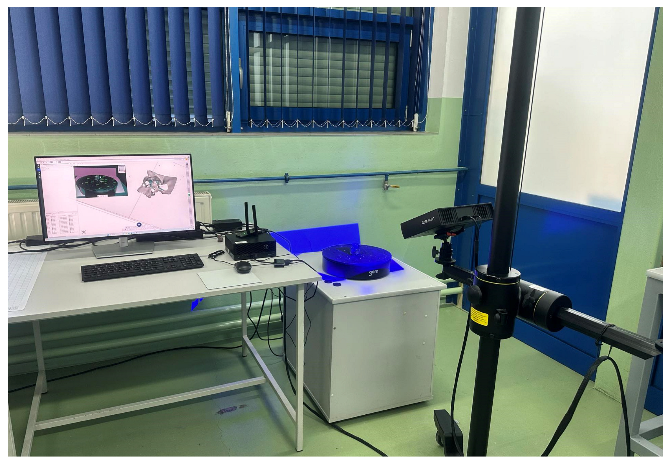
| Parameters | Value |
|---|---|
| Pixel-resolution cameras | 5,000,000 |
| Measuring area | 100 mm × 65 mm × 400 mm |
| Min. point resolution | 0.037 mm |
| Number of points per scan | 5,000,000 |
| Number of rotations of the measuring table | 13 |
| Parameters | Cranial Model | Defect of the Zygomatic Bone |
|---|---|---|
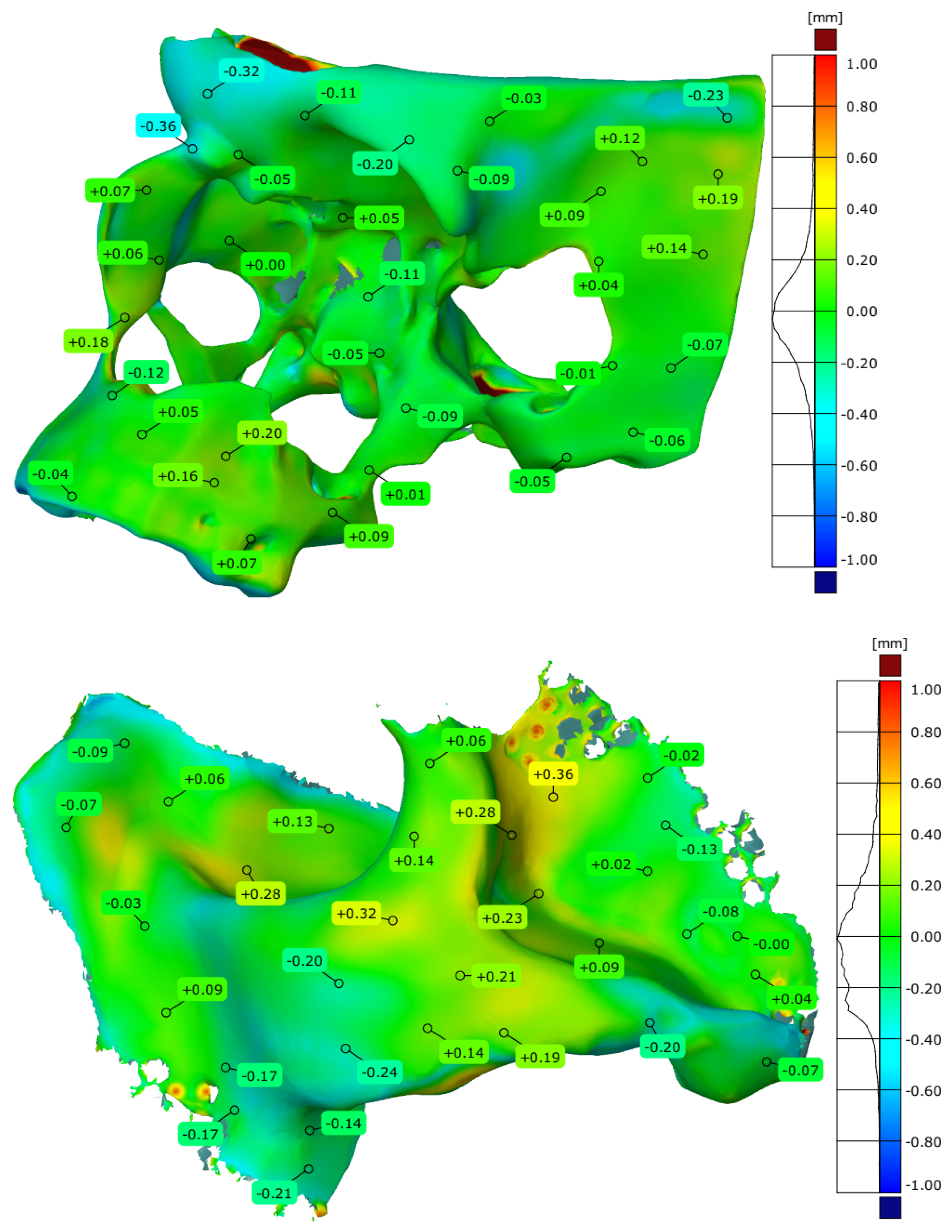
| Maximum deviation [mm] | 2.016 | 2.226 |
| Minimum deviation [mm] | −1.903 | −1.092 |
| Range [mm] | 3.919 | 3.318 |
| Mean deviation [mm] | −0.014 | −0.047 |
| Standard deviation [mm] | 0.277 | 0.340 |
| Parameters | Cranial Model | Defect of the Zygomatic Bone |
|---|---|---|
| Maximum deviation [mm] | 1.802 | 1.197 |
| Minimum deviation [mm] | −1.673 | −1.209 |
| Range [mm] | 3.475 | 2.406 |
| Mean deviation [mm] | −0.004 | −0.024 |
| Standard deviation [mm] | 0.242 | 0.290 |
| Parameters | Stamp Model | Die Model | Type of Mode |
|---|---|---|---|
| Maximum deviation [mm] | 0.827 | 0.687 | Normal |
| Minimum deviation [mm] | −1.394 | −1.396 | |
| Range [mm] | 2.211 | 2.082 | |
| Mean deviation [mm] | 0.009 | −0.014 | |
| Standard deviation [mm] | 0.341 | 0.230 | |
| Maximum deviation [mm] | 0.547 | 0.727 | Ultra-light |
| Minimum deviation [mm] | −1.443 | −0.696 | |
| Range [mm] | 1.990 | 1.423 | |
| Mean deviation [mm] | 0.020 | 0.045 | |
| Standard deviation [mm] | 0.259 | 0.193 |
Disclaimer/Publisher’s Note: The statements, opinions and data contained in all publications are solely those of the individual author(s) and contributor(s) and not of MDPI and/or the editor(s). MDPI and/or the editor(s) disclaim responsibility for any injury to people or property resulting from any ideas, methods, instructions or products referred to in the content. |
© 2025 by the authors. Licensee MDPI, Basel, Switzerland. This article is an open access article distributed under the terms and conditions of the Creative Commons Attribution (CC BY) license (https://creativecommons.org/licenses/by/4.0/).
Share and Cite
Turek, P.; Kubik, P.; Ruszała, D.; Dudek, N.; Misiura, J. Guidelines for Design and Additive Manufacturing Specify the Use of Surgical Templates with Improved Accuracy Using the Masked Stereolithography Technique in the Zygomatic Bone Region. Designs 2025, 9, 33. https://doi.org/10.3390/designs9020033
Turek P, Kubik P, Ruszała D, Dudek N, Misiura J. Guidelines for Design and Additive Manufacturing Specify the Use of Surgical Templates with Improved Accuracy Using the Masked Stereolithography Technique in the Zygomatic Bone Region. Designs. 2025; 9(2):33. https://doi.org/10.3390/designs9020033
Chicago/Turabian StyleTurek, Paweł, Paweł Kubik, Dominika Ruszała, Natalia Dudek, and Jacek Misiura. 2025. "Guidelines for Design and Additive Manufacturing Specify the Use of Surgical Templates with Improved Accuracy Using the Masked Stereolithography Technique in the Zygomatic Bone Region" Designs 9, no. 2: 33. https://doi.org/10.3390/designs9020033
APA StyleTurek, P., Kubik, P., Ruszała, D., Dudek, N., & Misiura, J. (2025). Guidelines for Design and Additive Manufacturing Specify the Use of Surgical Templates with Improved Accuracy Using the Masked Stereolithography Technique in the Zygomatic Bone Region. Designs, 9(2), 33. https://doi.org/10.3390/designs9020033