1. Introduction
Together with the rapid advances of new materials and new technologies, there is an emerging trend among researchers, designers, and artists to imbue new techniques into traditional arts and crafts to enable dynamic artwork creation that is more expressive and provides new designs that static artwork could not achieve [
1,
2,
3,
4,
5,
6]. One of the major categories is dynamic thermochromic graphic art creation, where designers leverage the nature of some materials’ color-changing pattern when being heated up and cooled down. Examples include thermochromic byobu [
7], thermochromic nihonga [
8], and thermochromic origami [
9].
However, creating thermochromic paintings needs coding and hardware development, which can be a challenge for artists and enthusiasts with non-technology backgrounds to create independently. Prior works on thermochromic paintings creation were mainly technology-driven studies rather than user-centred studies. Researchers developed thermochromic systems and regarded paintings as an application, which neglects the artists’ needs and pain points in the creation [
10,
11]. For example, PaperPixel [
10] demonstrated the feasibility of a Peltier-based thermochromic system on the creation of draft-level graffiti. It has strong constraints on thermochromic area size, which posed great limitations on creative freedom and could not meet the creative needs of artists. Phosphenes [
11] is a thermochromic system based on conductive silver ink. It only supports the design of the heating process, which limits the dynamic designing process. To the best of our knowledge, none of the prior works designed thermochromic systems around the artists’ needs in the painting scenarios. We aim to address the gap in this paper.
We present ViviPaint, a toolkit that includes a design tool (software) accompanied by a set of hardware components (shown in
Figure 1. The toolkit can provide artists, designers, and enthusiasts with a formalized pipeline to create thermochromic painting easily and independently. After finishing a thermochromic painting, users can use the design tool to pre-plan the animation. Moreover, the tool can generate useful, easy-to-follow guidance for the assembly stage. Following the guidance, users can then assemble the hardware kit together (including the painting, Peltier elements, and other components) and enjoy the procedure of creating the dynamic display.
We used Chinese painting as the exemplar application throughout the paper. Our research includes three parts. First, we collaborated with an expert artist to create a thermochromic painting, where we observed the full process of creating a thermochromic Chinese painting. We summarized the challenges and pain points encountered by the expert during the creation. These observations provide insights into the design of our toolkit.
Second, we designed ViviPaint that consists of both the software and the hardware design. The design tool (software) mainly provides three function types: (1) a GUI interface to choreograph animation and preview animation effects for users with non-technical backgrounds; (2) hardware assembly guidance in which users can use the design tool to pre-plan the layout of the Peltier elements and obtain a Peltier installation guide; and (3) reduce unnecessary labor work. Our design tool can generate an SVG line-drawing file for each decolorization area and send it to a digital cutting plotter to process the heat conductive layer automatically. As for the hardware, we provided a set of components with an easy assembly method, including an augmented picture frame with detachable structure to facilitate mounting and dismounting of the painting, and 24 temperature-changing units using Peltier elements.
Finally, We conducted an evaluation study by inviting eight participants to use our toolkit. In addition to successfully and independently creating dynamic thermochromic paintings, participants provided positive feedback that the toolkit is easy to use and can effectively assist the whole creation procedure. Beyond the user study, we also present a real application practice from a professional artist, who used ViviPaint for thermochromic painting creation and displayed the creation at a local museum. We concluded the paper by discussing the influence of the Peltier-based toolkit and generalizability for other graphical thermochromic artwork. We also discuss the potential of ViviPaint’s application beyond artistic creations.
The contributions of our paper are three-fold:
- 1.
We conducted a formative study with a professional artist on the genuine art practice of creating thermochromic paintings. Our results identify challenges and pain points of the current creation process for the first time.
- 2.
We proposed ViviPaint, a toolkit comprising a design tool and a set of hardware components. Users can follow a pipeline of software operation and hardware assembly to create their thermochromic paintings smoothly and independently.
- 3.
Through an evaluation study with eight participants, our results showed that ViviPaint is easy to use and can greatly support users during the thermochromic creation process.
2. Related Work
We first provide a brief overview of the domain of dynamic artwork. Then, we review thermochromic graphic art creation specifically followed by related toolkits built for creating thermochromic paintings.
2.1. Dynamic Artwork
Advances in new materials and technologies have attracted attention in the research and design field of dynamic artwork. In general, these dynamic artworks can be divided into two types: shape-changing and color-changing artworks. Each type of artwork also varies in the driving mechanism of the dynamic expression.
In terms of shape-changing artworks, typical dynamic mechanisms include mechanical-driven [
6,
12], fluid-driven [
4,
13], photo-deformation [
14], and thermo-deformation mechanisms [
15]. The mechanical-driven artworks use materials with specially designed mechanical structures to achieve the shape-changing effect. For example, Ion et al. [
12] used metamaterials with a well-defined 3D grid cell structure to create dynamic sculpture. Albaugh et al. [
6] used knitting fabrics with specially designed knitting tendons to create soft actuated objects. The fluid-driven artworks mainly achieve dynamic deformation by charging or discharging fluid into a specially designed fluidic channel structure. For example, Awakened Apparel [
4] used an inflatable origami structure to create deformable clothes. MilliMorph [
13] used fluidic chambers and channels at millimeter scale to create tangible dynamic objects. Regarding photo-deformation artworks, an example named Active Textile [
14] used composite photo-deformation material to create shape-changing textiles on which the perforations could be programmed to open or close in response to a light source. For thermo-deformation artworks, an example named Mulan [
15] used shape memory alloys (SMA) to create shape-changing embroidery artwork with petals that could bend in response to temperature to imitate the bloom of a flower.
In terms of color-changing artworks, typical dynamic mechanisms include fluid-based [
2,
16], photochromic [
17], and thermochromic mechanisms [
10,
11]. Specifically, fluid-based artworks mainly achieve the color-changing effect by changing the colorful fluid distribution in a specially designed fluidic channel structure. For example, Fluid Dress [
16] wove transparent flexible tubes containing dynamic colored fluid to create color-changing clothes. Venous Material [
2] carved fluidic channels at millimeter scale on a flexible transparent material to create tangible pressure-sensing color-changing objects. For photochormic artworks, an example named Photo-chromeleon [
17] used a composite photochromic dye to create repeatably colored artworks in which the color could change repeatably and programmatically under different projection exposures. Regarding thermochromic artworks, examples such as Phosphenes [
11], PaperPixel, [
10] and AmbiKraf [
7] used thermochromic pigments to create dynamic graphic artworks, which could change picture effect by changing color according to the temperature change. In our research, we focused on the creation of thermochromic graphic arts.
2.2. Thermochromic Graphic Art Creation
To create dynamic thermochromic graphic art, thermoelectric heating elements are needed to heat up and/or cool down the materials. One of the major elements is Peltiers. A Peltier element is a multi-size square-shaped semiconductor. By reversing the power supply, Peltier can switch between heating and cooling. Therefore, the Peltier element is modular and flexible, which is convenient for animating picture elements. Other examples also include infrared LEDs, conductive silver ink, and conductive yarn, etc. Overall, thermochromic graphic art can be summarized into two major categories: paper-based and textile-based.
For paper-based graphic art, Peltier is a popular choice as the heating element. For example, Peiris et al. collaborated with a Nihonga artist to create KineticCanvas [
8], which animates goldfish swimming around in a lotus pond. The author used thermochromic pigment to draw goldfish and attached a piece of Peltier element behind each goldfish. By controlling each Peltier element’s heating and cooling, the author could make the painting show only one goldfish at every moment in time and thus present the effect of the goldfish swimming along the trajectory. Some artists created paper-based artworks that can interact with audiences, such as Inkantatory paper [
18], Anabiosis [
19], and thermochromic origami [
9]. These works consist of a circuit layer made of conductive silver ink, a thermally conductive layer made of carbon powder, and a painting layer made of thermochromic pigments. When an audience’s finger touches the paper, it will trigger a color change on the paper’s front side. For example, the color of a butterfly’s wings will change when an audience puts their hand on the butterfly in the painting.
In terms of fabric-based graphic art, Peltier is also mainly employed as a heat-generating element [
20,
21,
22,
23]. For example, TempTouch [
24] can change color with the help of Peltier elements when a user touches the fabric; dMarkers [
25,
26] can display different QR code patterns according to the heating conditions. In the AmbiKraf byobu [
7,
27,
28], the authors applied thermal decolorizing pigments on the fabric and then carved flower-shaped copper sheets and pasted them on the Peltier elements. The byobu would then show a dynamic display of the flowers flashing in sequence in the electrified state. In addition to using Peltiers, researchers also leveraged conductive yarns knitting to create various thermochromic textile [
29]. For example, Kan et al. [
30] used thermochromic threads to sew their names on clothing so that they can be displayed when being touched. Song et al. [
31] designed a heart-shaped pattern on a dress whose color-changing frequency is controlled by the wearer’s heartbeat frequency. Devendorf [
32] used both conductive yarns and thermochromic yarns on double-layer fabrics. It has a button on the bottom layer for users to touch to change the fabric’s color. In addition, there are also creations such as thermochromic lace crafts [
33], thermochromic tapestry [
34], thermochromic tattoos [
35,
36], and thermochromic embroidery [
37].
A majority of thermochromic graphic arts are achieved by Peltier elements. Therefore, our toolkit focused on Peltier-based creation. As we will show in the next section, creation with Peltiers is not an easy process. Our toolkit aims to address these challenges.
2.3. Toolkit for Creating Thermochromic Painting
The rise of do-it-yourself (DIY) culture has fostered various toolkits that help users create their own artworks [
38,
39,
40,
41]. However, currently, there are very few toolkits built for thermochromic painting.
PaperPixel [
10] is a Peltier-based toolkit. It includes: (1) modularised plug-and-play type elements (PaperPixels elements) that can be attached on the back of a regular piece of paper; and (2) a graphical user interface that allows users to stage the animation in a timeline format. However, PaperPixel can only support draft-level graffiti and is too primitive to support formal artistic painting creation. Each decolorization area cannot exceed one Peltier’s size, which limits creative freedom. More importantly, PaperPixel does not take other significant factors in the whole painting creation process into account, such as dealing with wider thermochromic areas, making heat conduction layers, designing heat dissipation device, and planning Peltier layout. In contrast, our Peltier-based toolkit can address these issues.
In addition to the Peltier-based toolkits, there are also circuit-based and LED-based toolkits. Torres et al. created Phosphenes [
11] that allows users to design the circuit according to the target decolorization area and the decolorization time using a software design tool. Then, the circuit is printed with conductive silver ink and attached to the back of the painting to create dynamic displays. Yamada et al. [
42] developed a picture color control system based on the CMYK color mode. Researchers used thermochromic ink to print the picture and used an array of infrared LED lights behind the picture to generate heat, thus changing the picture effect by controlling each CMYK channel’s color. However, both conductive silver ink and infrared LED cannot switch between heating and cooling freely like Peltier elements, limiting the design space of art creation. In contrast, our toolkit leverages Peltier’s advantages of active heating and cooling and is designed to address challenges that existing toolkits cannot achieve.
3. Formative Study: Requirements of Creating Thermochromic Painting
Before designing and building our toolkit, we conducted a formative study to identify the requiremenmts and pain points during the dynamic thermochromic painting process. We collaborated with a professional artist to create a large-scale 135 × 50 cm thermochromic painting, “Nine Orchids” (
Figure 2). The flowers in the painting show a dynamic effect of blooming and disappearing in sequence every 10 minutes.
The overall creation practice is visualized in
Figure 3. We first introduce the whole procedure in detail. Then, we summarize our observations.
3.1. Thermochromic Mechanism
We use thermal decolorizing powder to make the painting pigment in our study, which becomes transparent when the temperature rises higher than a particular decolorizing temperature and reappears when the temperature decreases. We painted “Nine Orchids” using the thermal decolorizing powder with two different decolorizing temperatures at 31 °C and 45 °C. When we encountered the situation where two flowers overlapped each other, we used the 45 °C thermal decolorizing powder to draw the flowers in the front and used the 31 °C decolorizing powder to draw the ones at the back so that the flowers could “bloom” from front to back in sequence when the temperature decreased gradually.
3.2. Conception and Painting
In the conception step, the artist first made a draft drawing and used image processing software (Photoshop in our study) to design animation effects. Then, the artist printed a copy of the draft drawing with the same size as the target painting and placed it below a sheet of rice paper for easy reference while painting. The artist also planned the usage of the thermochromic pigments according to the animation design.
After finishing the conception, the artist prepared the thermochromic pigment by mixing the thermal decolorizing powder with special glue (the same method of using mineral Chinese painting pigment). The mixed solution can be further diluted with water for concentration adjustment. When the thermochromic pigments were ready, the artist started painting on the rice paper.
3.3. Assembly Process
After completing the painting, we carried out the assembly process as follows.
(A) Frame and mounting. Because of the large labor work of frame and mounting, we sought the help of a picture framer to assist in this step. The picture framer pasted the fragile rice paper painting onto a sheet of thick paper to make it more robust and then assembled the painting into a picture frame structure. The picture frame structure includes an outer frame, a piece of decorative cardboard, and a wooden backing board on which the painting was pasted. The picture framer hollowed the backing to expose the thermochromic area as we needed to paste the Peltier elements behind the painting.
(B) Making the thermally conductive layer. According to the size of the flowers, we used Peltiers in three sizes: 2 × 2 cm, 3 × 3 cm, and 4 × 4 cm. Each Peltier element is square-shaped, while each flower is irregularly shaped and larger than one Peltier element. Therefore, it is necessary to make a thermally conductive layer to diffuse heat to the regions of the flowers not covered by the Peltier elements. We used copper tape with a thickness of 0.05 mm as the thermally conductive layer. We used a piece of carbon paper to copy the flower outline onto the copper tape and used scissors to cut off the flower-shaped pieces of the copper tape along the outline. Then, we pasted these copper tape pieces as the thermally conductive layer on the back of the corresponding thermochromic area of the painting.
(C) Installing Peltier elements and the heat dissipation device. We used copper tape to paste the NTC3590-10k thin-film thermistor onto the Peltier surface to provide the temperature feedback for the control circuit. We used thermally conductive double-sided tape to paste the Peltier element to the corresponding position on the back of the painting. Next, to facilitate animation choreography and debugging, we numbered the Peltier elements and associated the Peltier index with the painting’s thermochromic area. Then, we connected the Peltier elements to the circuit board, arranged and bundled the wires, and hid the wires inside the picture frame. After that, we installed a heat dissipation device with screws on the back of the picture frame. The heat dissipation device comprises an aluminum heat sink and two electric fans, and it is used to assist in heat transfer for Peltier elements. We used thermal grease to attach the aluminum heat sink to the Peltier element closely. Thermal grease can stay viscous. Therefore, if a Peltier is damaged, removing the heat dissipation device for replacement is convenient.
(D) Coding and testing the animation. At last, we translated the animation design to each Peltier element’s temperature-changing process and wrote the temperature control codes for Arduino manually. Then, we ran the codes to test the animation effect of the painting. This step was conducted iteratively to determine the final animation effect.
Figure 2 presents the finished artwork.
3.4. Pain Points and Requirements in Art Practice
We observed several pain points encountered during the creation procedure and summarized the creation requirements.
3.4.1. Requirements in Conception and Painting Stage
In the formative study, we did not limit the thermochromic areas’ shape, size, and position, aiming to provide as much creative freedom as possible and successfully create the artwork “Nine Orchids”. Creative freedom is important to formal artistic creation. However, it is ignored by a prior study [
10]. Each thermochromic area could not exceed the size of one Peltier element, thus limiting creative freedom and being too primitive to support a formal artistic creation. For the toolkit design, we should preserve the creative freedom we brought into the formative study. A toolkit should allow users to position multiple Peltier elements to one thermochromic area and control their cooling or heating together.
3.4.2. Pain Points and Requirements in the Assembly Process
We observed the following pain points that affect the independent creation of the thermochromic painting through the formative study, which the prior study [
10] also ignored.
(A) Time-consuming external resources required for frame and mounting. In the creation process, the artist had first to design the connection structure between the picture frame and the heat sink (for heat dissipation). Then, she needed to resort to an external painting and calligraphy mounting agency to customize the picture frame, which involved bringing the painting, circuit board, and heat sink to the agency and communicating with the picture framer back-and-forth. This process was time-consuming and not related to the art creation, costing the artist extra energy. To address these issues, a toolkit should provide a complete set of components that users can independently assemble to avoid the inconvenience of seeking external support.
(B) Tedious procedure of making the heat conductive layer. During the assembly process, the artist made the heat conductive layer by hand. For a large-scale painting such as “Nine Orchids”, the artist needs to cut a large number of pieces of copper tape, and most of them are in complex shapes. We found that this manual process can be simplified and automated. A toolkit should allow users to easily define the thermochromic areas in the software (e.g., circling them out), and the toolkit can generate a process file (e.g., an SVG line-drawing file) of the thermally conductive layer, which can be processed by a cutting plotter (widely available in local printing shops).
(C) Complex steps when installing Peltier Elements. To install Peltier elements correctly, the artist had to carry out complex installation planning, paste the Peltier elements behind the thermochromic area, number the Peltier elements manually, connect them to the circuit board, and arrange the wires to avoid them covering the Peltier surfaces. These steps were error-prone and required lots of attention from the artist. Although pasting Peltier elements and connecting them to the circuit board still have to be performed manually by the user, a toolkit can provide a clear Peltier installation guide, including where to paste the Peltier elements and on which socket to connect the Peltier to the circuit to reduce the planning burden.
(D) Inaccessible animation choreography procedure. For now, the animation code was translated from the animation design and written on the computer manually. For users without a technical background, this requires prohibitively high learning costs. A toolkit should make this procedure more accessible so that users can choreograph animations intuitively (e.g., with the help of a visual programming interface).
4. ViviPaint: A Toolkit for Creating Thermochromic Painting
Our findings from the formative study serve as meaningful guidance for the design of ViviPaint. The toolkit aims to support artists and enthusiasts with non-technology backgrounds to create dynamic thermochromic paintings independently. In this section, we introduce the two major parts of our toolkit: (1) the software part: a design tool; and (2) the hardware part: a series of hardware components.
4.1. Design Tool
As we want to preserve the creative freedom from the formative study, there are a few assignments that we expect the GUI design tool should help complete for the users:
Thermochromic Area Design: Enable users to easily define thermochromic areas and convert them to vector graphic files for processing the thermally conductive layer with digital tools, e.g., a cutting plotter.
Thermochromic Animation Creation: Assist users in choreographing animation intuitively and previewing the animation.
Peltier Layout Arrangement: Allow users to experiment with different layouts of Peltier elements as heating and cooling sources.
Peltier Installation: Provide users with clear guidance on connecting Peltier elements to the circuit board.
We implemented our design tool with Qt5 in a laptop/PC environment.
Figure 4 illustrates the step-by-step user interfaces and workflow. The overall workflow consists of the following four steps.
(A) Define thermochromic areas. Users take a photo of the painting and upload it to the design tool. They need to specify the actual length and width first, which will influence the layout of the Peltier (Step C). Users then draw and define the thermochromic areas on the canvas with the lasso tool. If the drawing path cannot form a closed area, it will automatically close with a line segment. When a new area is created, the interface will show an edit menu with two buttons for users to confirm or cancel the area.
(B) Design animation choreography. This step enables the user to choreograph animation with an intuitive GUI interface and provides a real-time preview. Each thermochromic area (defined in Step A) corresponds to a timeline track. We define the blank area on the timeline as the decoloration state (temperature ≥31 °C (In this version of the toolkit, we use 31 °C thermal decolorizing powder as the thermochromic pigment.)) and the black block on the timeline as the color’s appearance state (temperature < 31 °C). Users can add the black block by clicking on the plus button, delete it with a right-click, drag the block along the timeline to change its position, and drag the block’s end line to change its length. Users can also adjust the timeline’s total length and zoom in and out. The timeline metaphor enables the users to focus on designing the schedule of when the color appears and how long it remains without referring to the relationship between temperature and color status.
To preview the animation, users can drag the time indicator or click the PLAY button of the timeline. We use a solid-filled mask covering the thermochromic area and adjust its transparency to simulate the color-changing process. When the time indicator enters a blank area, we linearly fade in the mask, covering the painting, and simulate the decolorizing effect. When the time indicator enters a black block, we linearly fade out the mask, revealing the painting, and simulate the reappearance of the color. The color of the mask is determined by averaging the RGB color of all pixels in the painting to imitate the background color of the painting. The fade in and out process both last for 5 s as a hint to imitate the physical color-changing process. (Note that the 5 s length is only a hint which is an empirical estimate from the formative study of “Nine Orchids” since the length of the actual physical color-changing process naturally fluctuates within a few seconds affected by various factors, e.g., the environment temperatures or the heat dissipation effect).
(C) Arrange Peltier elements. In this procedure, users need to position Peltier elements to cover the thermochromic areas. The toolkit provides three types of Peltier elements: 2 × 2 cm, 3 × 3 cm, and 4 × 4 cm, and each type includes eight pieces with an index. Users can add a certain type of Peltier element by clicking the ADD button under the corresponding Peltier icon and then drag or rotate it to cover a thermochromic area. Users can position multiple Peltier elements to one thermochromic area and control their cooling or heating together. The remaining numbers of each type of Peltier are shown in real time, and users can click the RESET button to reset the Peltier arrangement.
(D) Generate and download files. After the first three steps, the design tool will generate three files automatically: (1) an SVG line-drawing file of the thermochromic area to process the copper thermal conductive layer with digital tools, (2) a piece of Arduino code that controls the heating and cooling process based on the design in Step B and Step C, and (3) a Peltier installation guidance of Peltier elements position and circuit board connection, which is generated by an optimization algorithm to minimize the intersections of wires. Users just need to simply export the three files and leverage them in the later procedure.
4.2. Hardware Implementation
In addition to the design tool, we also provide a series of hardware components to help users create the thermochromic painting independently. In this section, we introduce the architecture of the hardware, the mechanism of the temperature control, and the result of the technical evaluation of the thermochromic effect.
4.2.1. Architecture of the Hardware
The overall structure of the hardware is an augmented picture frame. The user can use the hardware to control the temperature of the painting and display the thermochromic animation. The architecture of the hardware is illustrated in
Figure 5, which comprises three types of components: common components for picture mount and display, thermal and electronic components for heat control, and a few necessary mechanical components for fixing.
We intend to design the hardware in such a way that creators without a technology background can go through the thermochromic painting creation process, from assembly to display, independently and smoothly, which is ignored by former studies. Hence, we only leave a few components detachable and easily assembled. These include the customized components (e.g., the painting) and a few accessories (e.g., the heat dissipation device). Users can assemble them simply with screws and connectors, then refer to the guidance from the GUI design tool for sophisticated installation (e.g., Peltier elements and the thermally conductive layers). For the components with no need to be replaced (e.g., the programmable circuit and the power supply), we pre-installed them on the frame to simplify the assembly process. The detailed assembly pipeline is introduced in
Section 4.3.
4.2.2. Mechanism of the Temperature Control
To support the thermochromic creation with more complexity and freedom, we propose a temperature-changing unit (TCU) as an elemental working unit to sense and change the temperature of the irregular-shaped areas of the thermochromic painting in our study. The units are installed on the back of the painting, driven by a programmable circuit to realize the temperature control. Here, we introduce the detailed temperature control mechanism.
The
temperature-changing Unit (TCU) is composed of four parts, shown in
Figure 6: the Peltier element, the temperature sensor, the thermally conductive layer, and the heat dissipation device. The four parts adhere together with thermally conductive silicone grease or thermally conductive tape. The details of the four parts are as follows:
The
Peltier element is the thermoelectric element in one TCU. As designed in the software (
Section 4.1), we provide three types of Peltier elements (2 × 2 cm, 3 × 3 cm, and 4 × 4 cm), and eight pieces for each type. The working voltage is 5 V for 2 × 2 cm Peltier elements and 12 V for 3 × 3 cm and 4 × 4 cm elements.
The temperature sensor is used to measure the surface temperature of a working Peltier element as the feedback of the closed-loop temperature control. We use the NTC3950-10k thermistor as the temperature sensor. In each TCU, the temperature sensor is pre-adhered to the Peltier element with copper tape before the user’s assembly process.
The
thermally conductive layer is made of 0.05 mm copper tape, which is used to transfer the temperature-changing effect of the Peltier element to the whole irregular thermochromic area to which it is adhered, beyond the fixed Peltier size. As designed in the software (
Section 4.1), if one thermochromic area is too large to be driven by one Peltier element in one TCU, multiple TCUs may share the same thermal conductive layer and drive temperature changing synchronously.
The heat dissipation device is implemented by heat sinks adhered to the backside of the Peltier elements and are used to assist in heat transfer for Peltier elements. The Peltier element can either use a separate heat sink or share a larger heat sink with other Peltier elements. In this toolkit version, we use a large heat sink (27 × 27 × 1.5 cm) as the common heat dissipation device for all TCUs in use. In addition, we also install two 12 V electric fans on the back of the heat sink to enhance the heat dissipation effect further.
The temperature control circuit is used to control the temperature of up to 24 TCUs programmatically. The user only needs to upload the control code generated by the GUI design tool to the micro-controller and plug in the Peltier elements of TCUs to the corresponding sockets on the circuit board. Then the circuit will be configured to control the temperature of the TCUs according to the customized animation design in the software. We use a Arduino Mega Pro as the micro-controller, where an On–Off control algorithm is launched to switch the temperature of the TCU between two pre-defined temperature levels. The micro-controller drives a full-bridge circuit for each TCU to adjust the on–off state and the direction of the current of the Peltier element and eventually decides whether the TCU is working in the heating, cooling, or resting state. The circuit also comprises power supplies.
4.2.3. Technical Evaluation of the Thermochromic Effect
We used a painted test pattern and one single TCU to conduct the technical evaluation of the thermochromic effect. We used the 31 °C thermal decolorizing powder to paint the test pattern and set the working temperature range of the TCU to 20–40 °C. We conducted two groups of tests with different designs of the TCU composition. The group design and the test setup are shown in
Figure 7 where Test Group One used the same thermal conductive layer covering the whole painting area but varied the Peltier element size, which was expected to test the maximum thermochromic area of one single TCU. Test Group Two used an area-limited thermal conductive layer with an irregular flower-shaped outline, which was expected to test the heat transfer effect of the thermally conductive layer. Under each test condition, we conducted at least three trials for either the heating or the cooling process. We recorded the surface temperature-changing curves of the Peltier element and the color-changing videos of the thermochromic test pattern. The temperature of the environment was 25 °C.
Figure 8 shows the surface temperature-changing curves of the Peltier element in different sizes. We found that the surface temperatures could reach the temperature set points for all three types of the Peltier element. In the heating trial, the temperatures all reached 40 °C within 5 s, and in the cooling trial, they reached 20 °C within 12 s.
Figure 9 shows the color-changing captures of the thermochromic test pattern. As for Test Group One, in the heating trial, the decolorizing areas expanded rapidly within 5 s for all three types of Peltier elements, reaching a diameter of 2.9, 4.5, and 5.3 cm, respectively, in the ascending order of Peltier size. During 5–20 s, the decolorizing areas remarkably decelerated the expansion and ultimately reached a maximum diameter of 4.3, 5.7, and 6.6 cm respectively, which indicated the maximum thermochromic area of one single TCU with different Peltier sizes. (Note that the diameter is measured approximately because of the blurred outline of the decolorizing area.) In the cooling trial, the decolorizing areas began to reappear at 5 s, changed rapidly during 5–7 s, and reappeared completely around 10 s.
As for Test Group Two, we limited the size of the flower within the maximum thermochromic diameter of the 3 × 3 cm Peltier, which is 5.7 cm, observed from Test Group One. In the heating trial, the flower decolorized mostly at 5 s and completely at 7 s, while the outline was also much clearer compared to the decolorizing area in Test Group One. In the cooling trial, the flower reappeared mostly at 5 s and completely at 7 s. The above results may indicate the guidance meaning of the maximum thermochromic area measured in Test Group one: If a user-defined thermochromic area is smaller than the maximum thermochromic area of one TCU, it is recommended that the user uses just one TCU to drive this area. In contrast, if the user-defined area is larger, it is recommended that the user uses more than one TCU to drive that area. In addition, the clear outline of the decolorizing flower also indicates the accuracy of the heat transfer effect by the thermally conductive layer.
4.3. The Overall Usage of the Toolkit
With the above software and hardware in ViviPaint, we now address the overall usage of the toolkit. Note that before using the toolkit, the users need to finish the painting and mount it on the inner wooden frame in
Figure 5 as preparation. After that, the user can use ViviPaint to complete the remaining creation process through a few steps as follows.
(A) Design tool operation. As shown in
Figure 10 (1,2), a user takes a photo of his painting and imports it to the design tool. Then the user operates the design tool, follows the four steps in
Figure 4, and obtains the files which facilitate the hardware assembly.
(B) Make the thermally conductive layer. As shown in
Figure 10 (3,4), the user imports the SVG line drawing file generated by the design tool to the cutting plotter to process the copper thermal conductive layer. (Cutting plotters are widely available. If the user does not have personal cutting plotters, the user can go to local printing shops to process the thermally conductive layer or cut it off with scissors following the guide of a printed SVG line-drawing file generated by the design tool.) The user then pastes the thermally conductive layer on the back of the corresponding thermochromic area of the painting with a light table’s assistance.
(C) Assemble the hardware components. First, as shown in
Figure 10 (5), the user installs the inner wooden frame with the painting mounted using connectors and screws. Next, as shown in
Figure 10 (6,7), following the installation guide from the design tool, the user matches the Peltier elements to the corresponding thermochromic area, adheres them with thermal grease, and then connects the Peltier wires to the corresponding sockets on the circuit board. After that, the user arranges the wires to avoid covering the Peltier surface. Then, as shown in
Figure 10 (8), the user applies thermally conductive silicone grease on the backside of the Peltier elements and installs the heat dissipation device using connectors and screws.
(D) Run the circuit control code. Finally, the user uploads the code generated by the design tool to Arduino Mega Pro through a USB, runs the code, and watches the thermochromic animation.
5. Evaluation
We conducted a workshop to evaluate how well ViviPaint can assist a user in creating thermochromic paintings.
5.1. Participants and Apparatus
We recruited participants from a local Chinese painting interest group. Eight participants (four males, four females) were invited, ranging from 19 to 30 years old. Half of them majored in painting in college, and half were enthusiastic amateurs with experience, having created at least 10 complete Chinese paintings.
Figure 11 shows the experimental site and apparatus. In addition to the ViviPaint toolkit, we also provided users with auxiliary tools, including 31 °C thermal decolorizing powder, a cutting plotter with copper tape, a screwdriver, thermal grease, and a light table. The working temperature of the hardware was set to 20–40 °C as the thermochromic effect test in
Section 4.2.3.
5.2. Procedure
The experiment consisted of two stages: painting (doing it independently) and assembly (using ViviPaint). In the painting stage, we held a workshop to introduce our toolkit, distributed thermochromic powder and the wooden inner picture frame to participants, and explained how to use them. We asked participants to complete a thermochromic Chinese painting with a size of 30 × 30 cm within one week. Participants were free to choose any content and subject matter without composition restrictions.
In particular, since there was only one toolkit set, participants could not take it out of our lab and try it while painting. To avoid affecting their creations, we introduced the color-changing mechanisms and effect of the toolkit to the participants. We told participants that Vivipaint could bring an animation effect of slow color changing to multiple centers. Due to heat diffusion from Peltier to the surroundings on the heat conductive layer, such an effect can support a typical artistic concept of Chinese painting—the blooming effect. Moreover, as large decolorization areas require multiple Peltiers to drive the color changing and there is space between Peltier elements, a decolorization area will show a multi-center effect rather than uniformly discoloring. To facilitate the participants’ understanding, we also showed them the video of “Nine Orchids’" animation effect and answered all their questions on the spot.
After the workshop, participants drew their paintings independently. After completing the painting, participants mounted the painting on the wooden inner frame. Once finishing the above steps, participants brought their works for the assembly stage according to the agreed time. Participants followed our 15 min tutorial of ViviPaint. In addition, we also prepared a 2 min video tutorial. We encouraged participants to solve problems independently, such as looking for solutions by viewing videos, when encountering difficulties. When it was difficult to find a solution, they could ask us for help. Then, they started to use the toolkit to design thermochromic areas and animation choreography, create the thermally conductive layer, assemble the inner and outer frame, install Peltier elements and the heat dissipation device, and view the final dynamic display (
Figure 4 and
Figure 10).
After completing the assembly, we first asked participants to fill in the System Usability Scale (SUS) [
43] to evaluate the usability and learnability of ViviPaint. Then, we conducted a semi-structured interview with participants. Participants first introduced their artwork. Then, we asked them about their experience using the toolkit and whether the paintings’ dynamic effects met their expectations. When interesting points emerged, we followed up with questions to obtain more details and concrete examples. We recorded the interview using audio recording and transcribed it into text for later analysis.
5.3. Quantitative Results
All the participants finished the experimental tasks successfully. The mean completion time of the assembly stage was around 2 h (116.4 ± 59.0 min).
Table 1 shows the average score of the 10 questions of the SUS questionnaire. The overall SUS score was 76.56 out of 100, indicating the great usability of our toolkit. In addition, we calculated the subscale score. The subscale composed of Q4 and Q10 is “Learnability”, and the subscale composed of the other eight questions is “Usability”. The learnability score was 56.38 (out of 100, medium), and the usability score was 80.86 (out of 100, high). The medium learnability score indicates that our toolkit is not difficult to learn. Because our toolkit consists of both software and hardware components, users inevitably need to spend some time learning the toolkit. However, in the tutorial session, participants could quickly pick up the toolkit (13.8 ± 5.1 min). Therefore, we envision that the learning procedure of ViviPaint will be smooth in real usage scenarios.
5.4. Qualitative Results
Towards the end of the study, participants came back with a variety of paintings which are shown in
Figure 12. In this section, we report the qualitative results from the perspective of art creation and usability.
5.4.1. Toolkit as an Inspiration of Art Creation
Through the interview, We found that participants had understood the color-changing mechanism of Vivipaint and transformed them into creation inspirations. For example, P5 and P8 used the multi-center and blooming effect to create the cloud and mist. When P2 conceived the picture, his idea was to find themes in nature similar to the color-changing effect of ViviPaint. Finally he succeeded in linking the fireflies’ halo effect at night with the color-changing effect of “appear–decolorization”. He told us:
“At first, I wanted to paint dynamic butterflies to show a group of butterflies flying by changing colors, but I thought again, this is not right. Because this pigment has only two states of appearing and disappearing, you cannot paint several layers with various color-changing points, so it is not appropriate to express the butterfly flying. So I gave up this idea. I went to the Internet to find a lot of pictures, and I saw the paintings made by the Japanese. I find that many Japanese like to paint night scenes, and also, it is exciting. Then I thought of this again. At first, I wanted to draw the moon. Then I thought about it. If I draw the moon, the whole picture will be too bright. The night inspired me to think of the effect of fireflies, which is the feeling of twinkling. I can do it with a single color, and the two states of appearing and disappearing can express the effect of gradually lighting the whole picture, so I chose this plan in the end”.
All users were satisfied with the dynamic effect, and P4 and P6 mentioned that it exceeded their expectations. P4 described his dynamic work as a gracious old cartoon: “It has met my expectations. The animation is still very kind and touching. To achieve this effect is like an old animation. If it is in a physical exhibition hall, although there are only one or two frames and simple animations effect, it still has a wealth of possibilities. It does provide a new dimension of innovation, showing such an effect in a physical image, which is very different from the feeling of the screen”. Participants agreed that our toolkit helped them open up new creative possibilities. As stated by P7: “Artists want to show what makes them unique. However, it is still difficult for Chinese paintings to change because the predecessors have accumulated mature techniques and themes. The combination of Chinese paintings, new materials, and new technology is a breakthrough point. I think this kind of dynamic Chinese painting will have rich creative possibilities”.
Through this creation, the participants deepened their understanding of toolkits and color-changing pigments and generated new creative inspirations. For example, the pigment will leave a trace after fading and will not disappear completely. After seeing that the squirrel she painted did not wholly decolorize, P7 had a new creative inspiration and believed that this color-changing painting, in which she hoped the color would decolorize, was a break from the daily concept. She says:
“I think the color has not completely disappeared, which inspired another creative idea: you can coat the background with that gray color. Its opacity will change, and you can express the feeling of floating in the water. The reflection of the moon in the water is also interesting. The original purpose of our painting is to let people see the color, but our pigment is to make it disappear. This is a break from our daily concepts, which can lead an artist to think about the painting itself. I think I can try any of my paintings in the future because I am also painting some freehand figure paintings. For example, if I paint some ancient clothes with red color, some colors or anything can be faded. There are also Buddhist themes. Initially, Buddhist themes were unwilling to let everyone paint and sketch, but now that perception has changed. We can use this disappearing pigment to express the earliest idea of this unwillingness”.
Both P5 and P3 wanted to create with the theme of changing seasons. P5 said: “In addition to being very suitable for expressing fog, I feel it is also very suitable for expressing seasonal changes. For example, I want to create a tree with leaves, then leaves a little light green, then green, and finally turning yellow”, P3 has already created works with the theme of seasonal changes and freehand brushwork techniques. She expressed that she would like to continue to create works using fine brushwork painting techniques in the future.
P8 believes the toolkit is very suitable for expressing light and shadow, so the toolkit can support creating dynamic experimental ink painting well. She said:
“A professor in our college who teaches experimental ink painting has a lot of light and shadow in his works. I think he is a great fit for creating with our kit. He painted the buildings of Huizhou, and I think it is very suitable for the light of the sky to shine on the buildings and furniture, including the landscapes”.
5.4.2. Usability
In terms of usability, the difficulties encountered by participants mainly came from the difficulty of using color-changing pigments. First, participants expressed their desire to obtain thermochromic pigments with richer color-changing capabilities, such as different pigments with different color-changing points, or a pigment that can decolorize at low temperatures and reappear at high temperatures. The participants hoped to paint these various pigments in the same place to achieve multi-layered color-changing effects, thus expanding the creative space. Second, the pigments made from current thermochromic powders are relatively turbid, have poor transparency, and have rough textures. It will impact all types of paintings that require fine and smooth paint pigments. Lastly, the types of colors are limited. The lack of the color white, a commonly used color in traditional Chinese painting, affected the participants’ creation.
In terms of Vivipaint which mainly provides temperature and timing control, there are a few possibilities for improvement to better support art creation. For the design tool, most participants pasted more than one Peltiers behind one decolorization area to drive the entire site to change color. When virtually planning the Peltier layout using the design tool, participants completed this operation based on empirical knowledge to decide the Peltier layout that drives the entire area. In future research, researchers should study the quantitative model of the decolorization size versus the Peltier size and apply it to the design tool simulation to provide users with more guidance on the Peltier layout. Researchers could also quantitatively model the diffusion process of the decolorization area to further provide guidance on the decolorization effect by a more vivid simulation. Moreover, the design tool should be more intelligent; for example, it could let the system automatically plan the Peltier layout in each decolorization area.
As for hardware, none of the participants thought these steps caused trouble for themselves. P1 even thought she enjoyed the assembly process. Some participants suggested some potential directions to further improve the toolkit. For example, P8 considered that a bobbin structure could be made inside the frame to help users arrange the wires because when the painting had many decolorization areas, arranging the wires would become troublesome. P2 also mentioned the opportunity to apply more kinds of sensors to the toolkit, such as a distance sensor or a microphone, to support artists creating interactive thermochromic paintings.
5.5. Leveraging ViviPaint beyond User Studies
After the end of this study, we are excited to find that ViviPaint continues to inspire artists who are interested in our project to create new artwork. For instance, an artist created a group of works called “Candle”, which drew on ViviPaint’s slow color-changing and blooming effect. (
https://www.youtube.com/watch?v=MuF8DU4iwBQ, accessed on 5 September 2021). These artworks are displayed in a well-known local art museum (
Figure 13).
We envision that such co-creation can bring unique interactions between art and technology and promote both art and technology by putting new requirements on technical capabilities and inspiring new possibilities for artistic creation. We also hope that our research can inspire other researchers to incorporate new technologies into the creation of traditional art of their nation and expand the boundaries of artistic creation.
6. Discussion
We systematically explored thermochromic painting’s creative process, analyzed each step’s pain points, and provided solutions through a digitalized, automated, and standardized method, thereby designing a toolkit ViviPaint for thermochromic painting creation. The results of our user study indicated its effectiveness. In this section, we discuss the Peltier-based toolkit’s influence on thermochromic painting, generalizability for other graphical thermochromic artwork, and potential of ViviPaint to go beyond artistic creation.
6.1. Peltier-Based Toolkit for Thermochromic Painting
ViviPaint supports thermochromic painting creation without compromising on artistic freedom. Artists are free to design their own animation effects and painting composition because of the flexible positioning of Peltier elements supported by ViviPaint. Hence, thermochromic creations such as "Nine Orchids" that involve decolorization areas of different shapes, sizes, and locations can be easily produced using ViviPaint. The flexibility of the Peltier arrangement also makes our toolkit compatible with works of other sizes.
However, like the general restrictions confronted by all existing Peltier-based solutions [
8,
10], our toolkit still faces a few problems, including the low resolution constrained by the Peltier element size, the simple animation effect of appear and disappear, the planar rigid installation requirement, and the high power consumption. In the future, we can apply Peltier elements in smaller sizes to support higher resolution. In addition, it is also interesting to explore other temperature control mechanisms, such as using fluid interface to change the thermal environment at the back of the picture. Fluid interface has attracted attention in HCI [
2,
44] because of its flexibility and good controllability in certain scenarios. We may be able to arrange fluid in different temperatures within pre-designed fluidic channels to achieve complex animation. A fluid interface may also consume less energy than a Peltier-based system, and support curved surface creation.
6.2. Generalizability for Other Graphical Thermochromic Artwork
In our study, we focused on Chinese thermochromic painting as our use case. From a technical point of view, ViviPaint has universal applicability to other thermochromic graphic art creations beyond Chinese painting, such as watercolor painting, printmaking, or even graphic fabrics (such as embroidery) and paper-cutting, as long as the author uses thermochromic pigments as the artistic medium. They can use our toolkit to complete the creation following the creation pipeline. Moreover, from an artistic point of view, the combination of thermochromic technique and other art categories is worth exploring to find a unique art value in the balance between art and technology.
The toolkit was applied on paintings with the size of 30 × 30 cm in the user study. However, this does not mean that we cannot create paintings of other sizes. Our flexible Peltier arrangement and the detachable structure of the circuit board and power supplies with the picture frame facilitate easy installation into another “custom” picture frame. In the future, we can further reduce the circuit’s size to assemble it into picture frames of different sizes, especially smaller than the frame in this toolkit version.
6.3. Application Potential of ViviPaint beyond Artistic Creation
In this paper, we developed ViviPaint from the pain point of creating thermochromic paintings, aiming to allow artists and painting enthusiasts with non-technical backgrounds to create thermochromic graphic creations independently. At the same time, we also see the application potential of ViviPaint beyond artistic creation.
ViviPaint has the potential to create a personalized ambient information display. In today’s high popularity of electronic and information technology, HCI researchers often look back to the handicraft era. They miss the joy and warmth brought by the intimate contact between hands and materials, which is different from mass mechanized production. Therefore, more and more researchers combine digital practice with handicrafts and conduct research in hybrid crafts [
6,
10,
11]. Therefore, compared to screen-based displays, the dynamic presentation provided by traditional materials such as paper will bring a unique production experience and aesthetic interest. Users can use ViviPaint to draw their favorite content and then link it with various data such as weather, physiological, and environmental data. For example, people tend to turn the air conditioner too low in summer. It is neither good for health nor for saving energy. Users can draw a personalized picture, such as a cartoon character, and link it with the air conditioner’s temperature. When the air conditioner’s temperature is too low, people can see the characters in the painting wearing down jackets. This display may be able to form a persuasive design humorously and unobtrusively, thereby promoting energy saving, emission reduction, and environmental protection.
Moreover, We can use ViviPaint as a technical probe to help researchers understand specific user groups. For example, we can ask senior citizens to conduct creative practice using ViviPaint to understand what this hybrid craft practice of combining art and technology can bring them, such as emotional experience. We can also conduct user studies on children or parents and children to research children’s creativity or promote collaborative communication between parents and children.
7. Limitation
We now summarize the limitations of this work. First, we limited the number of thermochromic areas, and the size of the Peltier elements also limits the resolution of paintings. Future work should increase the extendability of the circuit board and use smaller Peltier elements.
Second, we did not study the quantitative model of the decolorization area size versus Peltier element size and the diffusion process of the decolorization area over time. In the future, we can conduct more quantitative experiments, address relative math models, and apply them to the simulation in the design tool to provide users with more guidance. We can also allow users to adjust color-changing speed to create a richer dynamic effect. However, limitations may still exist in the accuracy of the quantitative models of almost all temperature-changing processes in thermochromic artwork creation due to the uncertainty of environmental factors, e.g., environment temperatures or the heat dissipation effect.
Third, we conducted an evaluation study with a small number of participants (eight) with their ages ranging from 19–30. In the future, we should conduct experiments with more people of multiple ages.
8. Conclusions
This paper presents ViviPaint, a toolkit that allows artists and enthusiasts to create thermochromic dynamic painting conveniently and independently. We introduce the design and implementation of the two major components of VivePaint: a design tool and hardware components. With the toolkit, users can easily design and create choreographic animation and obtain Peltier installation guidance, file making of the thermally conductive layer, and the circuit control code. Then, they can complete their creation through an assembly pipeline. An evaluation study and real applications show that our toolkit provides good usability and enables users to deeply engage in creative activity. We envision this work could provide valuable insights about the toolkit design of thermochromic graphical art creation and provoke more thoughts and discussion about art creation through mixing traditional arts with technology.
Author Contributions
Conceptualization, G.L., Y.Z., T.Y. and H.X.; software, T.Y., X.X. (Xiaomeng Xu) and M.G.; hardware, Z.Y., T.Y., Q.S. and T.Z.; user Study, G.L.,Y.Z., H.X.; data analysis, G.L.; writing—original draft preparation, G.L., T.Y.; writing—review and editing, X.X. (Xuhai Xu); visualization, H.X.; supervision, H.M.; project administration, G.L.; funding acquisition, H.M. All authors have read and agreed to the published version of the manuscript.
Funding
This research received no external funding.
Institutional Review Board Statement
Ethical review and approval were waived for this study, due to the evaluation study was a creative workshop. participants participated voluntarily and could leave at any time, without involving the collection of physiological data and privacy issues.
Informed Consent Statement
Informed consent was obtained from all subjects involved in the study.
Data Availability Statement
Data is contained within the article.
Acknowledgments
The authors thank Kaiwen Ye for the careful revision of the paper writing style.
Conflicts of Interest
The authors declare no conflict of interest.
References
- Post, E.R.; Orth, M.; Russo, P.R.; Gershenfeld, N. E-broidery: Design and fabrication of textile-based computing. IBM Syst. J. 2000, 39, 840–860. [Google Scholar] [CrossRef]
- Mor, H.; Yu, T.; Nakagaki, K.; Miller, B.H.; Jia, Y.; Ishii, H. Venous Materials: Towards Interactive Fluidic Mechanisms. In Proceedings of the 2020 CHI Conference on Human Factors in Computing Systems, Honolulu, HI, USA, 25–30 April 2020; pp. 1–14. [Google Scholar]
- Buechley, L.; Hendrix, S.; Eisenberg, M. Paints, paper, and programs: First steps toward the computational sketchbook. In Proceedings of the 3rd International Conference on Tangible and Embedded Interaction, Cambridge, UK, 16–18 February 2009; pp. 9–12. [Google Scholar]
- Perovich, L.; Mothersill, P.; Farah, J.B. Awakened apparel: Embedded soft actuators for expressive fashion and functional garments. In Proceedings of the 8th International Conference on Tangible, Embedded and Embodied Interaction, Munich, Germany, 16–19 February 2014; pp. 77–80. [Google Scholar]
- Jacoby, S.; Buechley, L. Drawing the electric: Storytelling with conductive ink. In Proceedings of the 12th International Conference on Interaction Design and Children, New York, NY, USA, 24–27 June 2013; pp. 265–268. [Google Scholar]
- Albaugh, L.; Hudson, S.; Yao, L. Digital fabrication of soft actuated objects by machine knitting. In Proceedings of the 2019 CHI Conference on Human Factors in Computing Systems, Glasgow, UK, 4–9 May 2019; pp. 1–13. [Google Scholar]
- Peiris, R.L.; Tharakan, M.J.; Cheok, A.D.; Newton, O.N. AmbiKraf: A ubiquitous non-emissive color changing fabric display. In Proceedings of the 15th International Academic MindTrek Conference: Envisioning Future Media Environments, New York, NY, USA, 28–30 September 2011; pp. 320–322. [Google Scholar]
- Peiris, R.L.; Nanayakkara, S.; Wijesinghe, V.; Minamizawa, K. KineticCanvas: Synergetic Effort Between Art and Technology. In Proceedings of the Annual Meeting of the Australian Special Interest Group for Computer Human Interaction, Parkville, VIC, Australia, 7–10 December 2015; pp. 575–578. [Google Scholar]
- Kaihou, T.; Wakita, A. Electronic origami with the color-changing function. In Proceedings of the Second International Workshop on Smart Material Interfaces: Another Step to a Material Future, Sydney, Australia, 13 December 2013; pp. 7–12. [Google Scholar]
- Peiris, R.L.; Nanayakkara, S. PaperPixels: A toolkit to create paper-based displays. In Proceedings of the 26th Australian Computer-Human Interaction Conference on Designing Futures: The Future of Design, Sydney, Australia, 2–5 December 2014; pp. 498–504. [Google Scholar]
- Torres, C.; Chang, J.; Patel, A.; Paulos, E. Phosphenes: Crafting Resistive Heaters Within Thermoreactive Composites. In Proceedings of the 2019 on Designing Interactive Systems Conference, San Diego, CA, USA, 23–28 June 2019; pp. 907–919. [Google Scholar]
- Ion, A.; Frohnhofen, J.; Wall, L.; Kovacs, R.; Alistar, M.; Lindsay, J.; Lopes, P.; Chen, H.T.; Baudisch, P. Metamaterial mechanisms. In Proceedings of the 29th Annual Symposium on User Interface Software and Technology, Tokyo, Japan, 16–19 October 2016; pp. 529–539. [Google Scholar]
- Lu, Q.; Ou, J.; Wilbert, J.; Haben, A.; Mi, H.; Ishii, H. milliMorph–Fluid-Driven Thin Film Shape-Change Materials for Interaction Design. In Proceedings of the 32nd Annual ACM Symposium on User Interface Software and Technology, New Orleans, LA, USA, 20–23 October 2019; pp. 663–672. [Google Scholar]
- Active Textile—Self-Assembly Lab. Available online: https://selfassemblylab.mit.edu/active-textile (accessed on 1 January 2018).
- Jing, G. Mulan: A Dynamic Embroidery. Available online: https://www.milab.design/project-04 (accessed on 15 May 2018).
- Bucketn, C. Fluid Dress. Available online: https://vimeo.com/16871362 (accessed on 1 July 2011).
- Jin, Y.; Qamar, I.; Wessely, M.; Mueller, S. Photo-chromeleon: Re-programmable multi-color textures using photochromic dyes. In ACM SIGGRAPH 2020 Emerging Technologies; Association for Computing Machinery: New York, NY, USA, 2020; pp. 1–2. [Google Scholar]
- Tsujii, T.; Koizumi, N.; Naemura, T. Inkantatory paper: Dynamically color-changing prints with multiple functional inks. In Proceedings of the 27th Annual ACM Symposium on User Interface Software and Technology, Honolulu, HI, USA, 5–8 October 2014; pp. 39–40. [Google Scholar]
- Tsuji, K.; Wakita, A. Anabiosis: An interactive pictorial art based on polychrome paper computing. In Proceedings of the 8th International Conference on Advances in Computer Entertainment Technology, Lisbon, Portugal, 8–11 November 2011; pp. 1–2. [Google Scholar]
- Wakita, A.; Shibutani, M. Mosaic textile: Wearable ambient display with non-emissive color-changing modules. In Proceedings of the 2006 ACM SIGCHI International Conference on Advances in Computer Entertainment Technology, Hollywood, CA, USA, 14–16 June 2006; p. 48-es. [Google Scholar]
- Peiris, R.L.; Nakatsu, R. A temerature-based touch-sensor for non-emissive textile displays. In CHI’13 Extended Abstracts on Human Factors in Computing Systems; Association for Computing Machinery: New York, NY, USA, 2013; pp. 1605–1610. [Google Scholar]
- Peiris, R.L. Integrated Non-light-Emissive Animatable Textile Displays. In Smart Textiles; Springer: Cham, Switzerland, 2017; pp. 71–101. [Google Scholar]
- Kushiyama, K.; Baba, T.; Doi, K.; Sasada, S. Temperature design display device to use peltier elements and liquid crystal thermograph sheet: “Thermo-Pict neo”. In ACM SIGGRAPH 2010 Posters; Association for Computing Machinery: New York, NY, USA, 2010. [Google Scholar]
- Peiris, R.L.; Nakatsu, R. TempTouch: A novel touch sensor using temperature controllers for surface based textile displays. In Proceedings of the 2013 ACM International Conference on Interactive Tabletops and Surfaces, St. Andrews, UK, 6–9 October 2013; pp. 105–114. [Google Scholar]
- Peiris, R.L.; Fernando, O.N.N.; Bee, C.S.; Cheok, A.D.; Ganesan, A.G.; Kumarasinghe, P. dMarkers: Ubiquitous dynamic makers for augmented reality. In Proceedings of the 10th International Conference on Virtual Reality Continuum and Its Applications in Industry, Hong Kong, China, 11–12 December 2011; pp. 217–224. [Google Scholar]
- Peiris, R.L.; Fernando, O.N.N.; Cheok, A.D. A Dynamic AR Marker for a Paper Based Temperature Sensor. In Proceedings of the Second International Conference on Ambient Intelligence; Springer: Berlin/Heidelberg, Germany, 2011; pp. 195–199. [Google Scholar] [CrossRef]
- Peiris, R.L.; Cheok, A.D.; Teh, J.K.S.; Fernando, O.N.N.; Yingqian, W.; Lim, A.; Yi, P.; Polydorou, D.; Ong, K.P.; Tharakan, M. AmbiKraf: An Embedded Non-Emissive and Fast Changing Wearable Display. In Proceedings of the ACM SIGGRAPH 2009 Emerging Technologies; Association for Computing Machinery: New York, NY, USA, 2009. [Google Scholar] [CrossRef]
- Peiris, R.L.; Tharakan, M.J.; Fernando, N.; Chrok, A.D. AmbiKraf: A Nonemissive Fabric Display for Fast Changing Textile Animation. In Proceedings of the 2011 IFIP 9th International Conference on Embedded and Ubiquitous Computing; IEEE Computer Society: Washington, DC, USA, 2011; pp. 221–228. [Google Scholar] [CrossRef]
- Song, M.; Jia, C.; Vega, K. Eunoia: Dynamically Control Thermochromic Displays for Animating Patterns on Fabrics. In Proceedings of the 2018 ACM International Joint Conference and 2018 International Symposium on Pervasive and Ubiquitous Computing and Wearable Computers; Association for Computing Machinery: New York, NY, USA, 2018; pp. 255–258. [Google Scholar]
- Kan, V.; Fujii, K.; Amores, J.; Zhu Jin, C.L.; Maes, P.; Ishii, H. Social textiles: Social affordances and icebreaking interactions through wearable social messaging. In Proceedings of the Ninth International Conference on Tangible, Embedded, and Embodied Interaction, Stanford, CA, USA, 15–19 January 2015; pp. 619–624. [Google Scholar]
- Song, M.; Vega, K. HeartMe: Thermochromic Display as An Expression of Heart Health. In Proceedings of the 2018 ACM Conference Companion Publication on Designing Interactive Systems, Hong Kong, China, 9–13 June 2018; pp. 311–314. [Google Scholar]
- Devendorf, L.; Di Lauro, C. Adapting double weaving and yarn plying techniques for smart textiles applications. In Proceedings of the Thirteenth International Conference on Tangible, Embedded, and Embodied Interaction, Tempe, AZ, USA, 17–20 March 2019; pp. 77–85. [Google Scholar]
- Kuusk, K.; Kooroshnia, M.; Mikkonen, J. Crafting butterfly lace: Conductive multi-color sensor-actuator structure. In Proceedings of the 2015 ACM International Joint Conference on Pervasive and Ubiquitous Computing and Proceedings of the 2015 ACM International Symposium on Wearable Computers; Association for Computing Machinery: New York, NY, USA, 2015; pp. 595–600. [Google Scholar]
- Berzowska, J. Very slowly animating textiles: Shimmering flower. In ACM SIGGRAPH 2004 Sketches; Association for Computing Machinery: New York, NY, USA, 2004; p. 34. [Google Scholar]
- Wang, Y.; Luo, S.; Lu, Y.; Gong, H.; Zhou, Y.; Liu, S.; Hansen, P. AnimSkin: Fabricating epidermis with interactive, functional and aesthetic color animation. In Proceedings of the 2017 Conference on Designing Interactive Systems, Edinburgh, UK, 10–14 June 2017; pp. 397–401. [Google Scholar]
- Kao, H.L.; Mohan, M.; Schmandt, C.; Paradiso, J.A.; Vega, K. Chromoskin: Towards interactive cosmetics using thermochromic pigments. In Proceedings of the 2016 CHI Conference Extended Abstracts on Human Factors in Computing Systems, San Jose, CA, USA, 7–12 May 2016; pp. 3703–3706. [Google Scholar]
- Devendorf, L.; Lo, J.; Howell, N.; Lee, J.L.; Gong, N.W.; Karagozler, M.E.; Fukuhara, S.; Poupyrev, I.; Paulos, E.; Ryokai, K. “I don’t Want to Wear a Screen” Probing Perceptions of and Possibilities for Dynamic Displays on Clothing. In Proceedings of the 2016 CHI Conference on Human Factors in Computing Systems, San Jose, CA, USA, 7–12 May 2016; pp. 6028–6039. [Google Scholar]
- Buechley, L.; Perner-Wilson, H. Crafting technology: Reimagining the processes, materials, and cultures of electronics. ACM Trans. Comput. Hum. Interact. (TOCHI) 2012, 19, 1–21. [Google Scholar] [CrossRef]
- Koizumi, N.; Yasu, K.; Liu, A.; Sugimoto, M.; Inami, M. Animated paper: A moving prototyping platform. In Proceedings of the 23nd Annual ACM Symposium on User Interface Software and Technology, New York, NY, USA, 3–6 October 2010; pp. 389–390. [Google Scholar]
- Qi, J.; Buechley, L. Electronic popables: Exploring paper-based computing through an interactive pop-up book. In Proceedings of the Fourth International Conference on Tangible, Embedded, and Embodied Interaction, Cambridge, MA, USA, 24–27 January 2010; pp. 121–128. [Google Scholar]
- Saul, G.; Xu, C.; Gross, M.D. Interactive paper devices: End-user design & fabrication. In Proceedings of the Fourth International Conference on Tangible, Embedded, and Embodied Interaction, Cambridge, MA, USA, 24–27 January 2010; pp. 205–212. [Google Scholar]
- Yamada, H.; Tanikawa, T.; Nishimura, K.; Rose, M.H. Paint color control system with infrared photothermal conversion. In Proceedings of the 8th International Conference on Advances in Computer Entertainment Technology, Lisbon, Portugal, 8–11 November 2011; pp. 1–8. [Google Scholar]
- Bangor, A.; Kortum, P.T.; Miller, J.T. An empirical evaluation of the system usability scale. Int. J. Hum. Comput. Interact. 2008, 24, 574–594. [Google Scholar] [CrossRef]
- Inoue, Y.; Itoh, Y.; Onoye, T. TuVe: A flexible display with a tube. In SIGGRAPH Asia 2018 Emerging Technologies; Association for Computing Machinery: New York, NY, USA, 2018; pp. 1–2. [Google Scholar]
Figure 1.
The left picture shows the ViviPaint toolkit. The four pictures on the right show the thermochromic area and three animation frames of the appearance and disappearance of mist.
Figure 1.
The left picture shows the ViviPaint toolkit. The four pictures on the right show the thermochromic area and three animation frames of the appearance and disappearance of mist.
Figure 2.
The artwork “Nine Orchids” (135 × 50 cm). The left picture shows three animation frames of the flower growth. The right picture shows a set of Peltier-based heating and cooling devices behind the painting. The device consists of 27 Peltier elements, 3 identical circuit systems, and a heat dissipation device. Each circuit system is mounted on a PCB which can control 10 Peltiers. It comprises an Arduino mega pro, five TB6612 driver chips, power supplies, and rectifier circuits. Each TB6612 driver can independently control two Peltier elements to cool and heat and support 1.2 A per channel. In addition, several heat sinks are used to cool the driver chips.
Figure 3.
The process in the art practice of “Nine Orchids”.
Figure 3.
The process in the art practice of “Nine Orchids”.
Figure 4.
The step-by-step user interfaces and workflow of the design tool: ((A), top) users easily design areas that need to have a thermochromic effect; ((B), middle) users design and preview the choreographing animation; ((C), bottom left) users can try different layout designs of three types of Peltier elements; ((D), bottom right) users download three files to facilitate the creation process: an SVG line-drawing file to process the thermally conductive layer, a piece of Arduino code to control heating/cooling, and a Peltier installation guidance.
Figure 5.
Architecture of the hardware: (A,B) photos of the front and the back views of the assembled hardware (The Peltier elements and the heat dissipation device are omitted.); (C) the exploded view of the hardware; the three groups of the components are color-coded; ORANGE: common components for picture mount and display, including the outer picture frame, the cardboard and the painting; BLUE: thermal and electronic components for heat control, including the Peltier element, the thermally conductive layer, the temperature sensor, the heat dissipation device, and the circuit and the power supply; GREY: necessary mechanical components for fixing, including the inner wooden frame, the metal frame, and the connector.
Figure 6.
Structure of the temperature-changing unit (TCU). The arrows show the assembly orientation of a TCU.
Figure 6.
Structure of the temperature-changing unit (TCU). The arrows show the assembly orientation of a TCU.
Figure 7.
The group design and the setup of the thermochromic effect technical evaluation: (A) the thermochromic test pattern for both Test Group One and Two is a 19 × 19 cm solid-filled rectangle; (B) in Test Group One, the thermally conductive layer is a 19 × 19 cm rectangle, and the Peltier element varies at 2 × 2 cm, 3 × 3 cm, and 4 × 4 cm; (C) in Test Group Two, the thermally conductive layer is a flower-shaped area within a diameter of 5.7 cm, and the Peltier element is at 3 × 3 cm; (D) the setup of the hardware test.
Figure 8.
The surface temperature-changing curves of the Peltier element in heating (left) and cooling (right) trial. SP stands for the temperature set point. PV stands for the process value of the Peltier surface temperature, the number that follows “PV” stands for the Peltier size in Test Group One, and the * symbol stands for Test Group Two.
Figure 9.
Captures of the color-changing videos of the thermochromic test pattern.
Figure 9.
Captures of the color-changing videos of the thermochromic test pattern.
Figure 10.
The use process of the toolkit: steps 1–2, design tool operation; steps 3–4, make the thermally conductive layer; steps 5–8, assemble the hardware components, including (5) the inner wooden picture frame, (6–7) the Peltier elements, and (8) the heat dissipation device.
Figure 10.
The use process of the toolkit: steps 1–2, design tool operation; steps 3–4, make the thermally conductive layer; steps 5–8, assemble the hardware components, including (5) the inner wooden picture frame, (6–7) the Peltier elements, and (8) the heat dissipation device.
Figure 11.
Experimental site and apparatus.
Figure 11.
Experimental site and apparatus.
Figure 12.
Thermochromic paintings created by the eight participants independently using ViviPaint.
Figure 12.
Thermochromic paintings created by the eight participants independently using ViviPaint.
Figure 13.
Thermochromic painting “Candle” by ViviPaint displayed in local art museum: (A–F) captures of the color-changing process of the two works of “Candle”; (G,H) photos of the exhibition venue.
Figure 13.
Thermochromic painting “Candle” by ViviPaint displayed in local art museum: (A–F) captures of the color-changing process of the two works of “Candle”; (G,H) photos of the exhibition venue.
Table 1.
Average score of the 10 statements of the SUS questionnaire. Note that Q2,4,6,8,10 highlighted in gray are negative questions, so we reversed the score when calculating the overall score.
Table 1.
Average score of the 10 statements of the SUS questionnaire. Note that Q2,4,6,8,10 highlighted in gray are negative questions, so we reversed the score when calculating the overall score.
| Statements | Average Score |
|---|
| Q1. I think that I would like to use ViviPaint frequently. | 4.13 (SD = 0.83) |
| Q2. I found the ViviPaint unnecessarily complex. | 2.38 (SD = 1.19) |
| Q3. I thought ViviPaint was easy to use. | 3.88 (SD = 0.83) |
| Q4. I think that I would need the support of a technical person to be able to use ViviPaint. | 3.00 (SD = 1.07) |
| Q5. I found the various functions in ViviPaint well integrated. | 4.38 (SD = 0.52) |
| Q6. I thought there was too much inconsistency in ViviPaint. | 1.25 (SD = 0.46) |
| Q7. I would imagine that most people would learn to use ViviPaint very quickly. | 4.13 (SD = 0.99) |
| Q8. I found ViviPaint very cumbersome to use. | 1.63 (SD = 0.74) |
| Q9. I felt very confident using ViviPaint. | 4.63 (SD = 0.52) |
| Q10. I need to learn a lot of things before I could get going with ViviPaint. | 2.25 (SD = 0.71) |
| Publisher’s Note: MDPI stays neutral with regard to jurisdictional claims in published maps and institutional affiliations. |
© 2022 by the authors. Licensee MDPI, Basel, Switzerland. This article is an open access article distributed under the terms and conditions of the Creative Commons Attribution (CC BY) license (https://creativecommons.org/licenses/by/4.0/).


 ,
, 


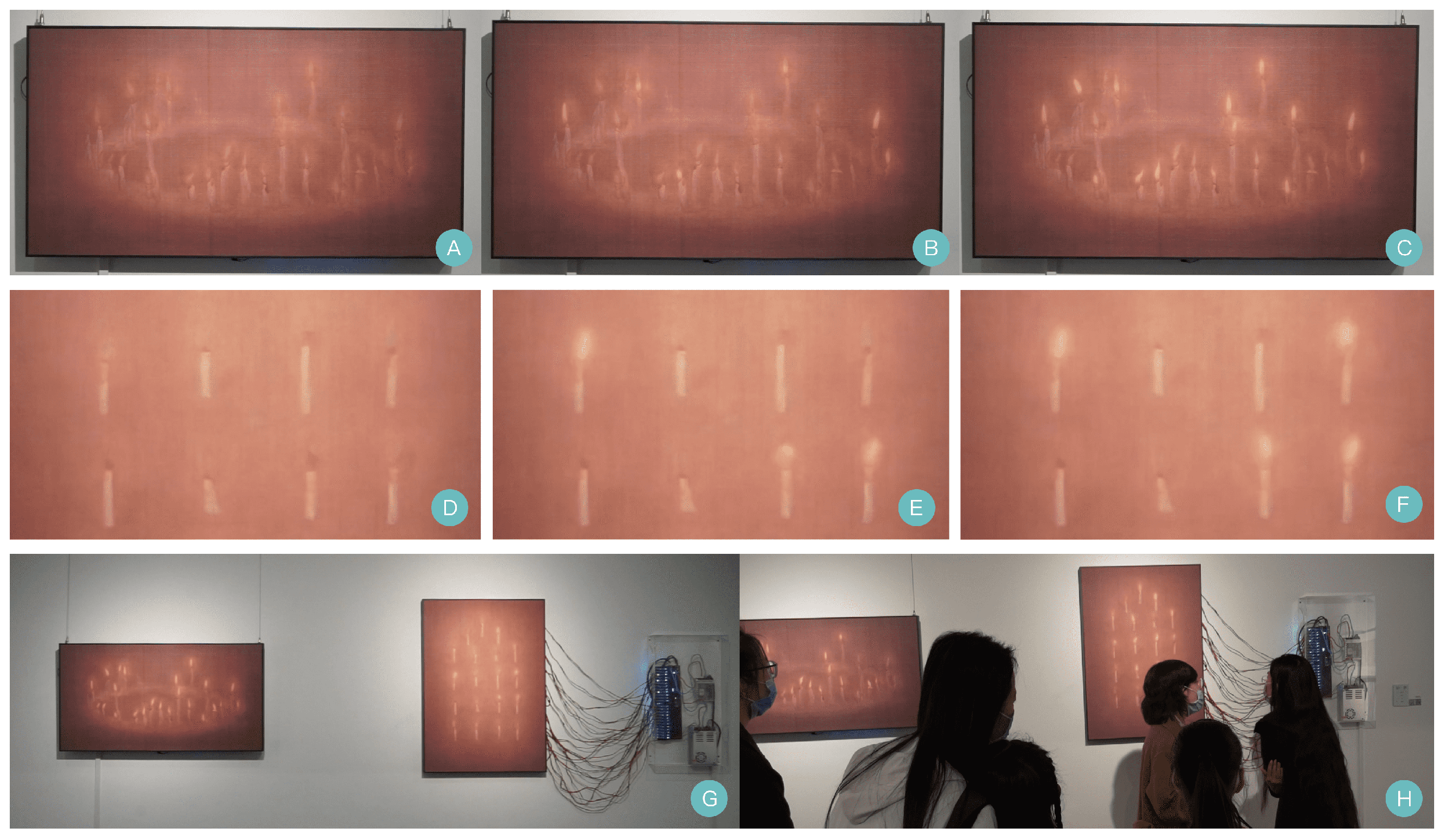
