Article

Optical Rules to Mitigate the Parallax-Related Registration Error in See-Through Head-Mounted Displays for the Guidance of Manual Tasks

1
Dipartimento di Ingegneria dell’Informazione, Università di Pisa, Via Girolamo Caruso 16, 56122 Pisa, Italy
2
EndoCAS Centre for Computer Assisted Surgery, Università di Pisa, Ospedale di Cisanello, Via Paradisa 2, 56124 Pisa, Italy
*
Author to whom correspondence should be addressed.
Multimodal Technol. Interact. 2024, 8(1), 4; https://doi.org/10.3390/mti8010004
Submission received: 26 October 2023 / Revised: 16 December 2023 / Accepted: 22 December 2023 / Published: 4 January 2024

Abstract

:
Head-mounted displays (HMDs) are hands-free devices particularly useful for guiding near-field tasks such as manual surgical procedures. See-through HMDs do not significantly alter the user’s direct view of the world, but the optical merging of real and virtual information can hinder their coherent and simultaneous perception. In particular, the coherence between the real and virtual content is affected by a viewpoint parallax-related misalignment, which is due to the inaccessibility of the user-perceived reality through the semi-transparent optical combiner of the OST Optical See-Through (OST) display. Recent works demonstrated that a proper selection of the collimation optics of the HMD significantly mitigates the parallax-related registration error without the need for any eye-tracking cameras and/or for any error-prone alignment-based display calibration procedures. These solutions are either based on HMDs that projects the virtual imaging plane directly at arm’s distance, or they require the integration on the HMD of additional lenses to optically move the image of the observed scene to the virtual projection plane of the HMD. This paper describes and evaluates the pros and cons of both the suggested solutions by providing an analytical estimation of the residual registration error achieved with both solutions and discussing the perceptual issues generated by the simultaneous focalization of real and virtual information.

1. Introduction

Recent research suggests that Head-Mounted Displays (HMDs) could improve worker performances in a variety of tasks [1,2,3]. HMDs indeed can deliver contextually relevant information in real-time while avoiding the unsafe eyesight shift away from the working area so that less mental effort is needed for compensating perspective differences. In surgery, there is a growing interest to guide manual tasks using virtual information that should be accurately aligned to the real target [4,5] as a virtual cutting line registered with the anatomy to perform the surgical resection [6]. In Augmented Reality (AR) HMDs, the see-through mechanism can be implemented through two main paradigms: video see-through (VST) and optical see-through (OST). In VST HMDs, the view of the real world is obstructed as it is mediated by one or two world-facing cameras. The camera views are first digitally merged with the virtual content and then rendered on the two microdisplays of the HMD. This approach, even if well implemented, introduces non-negligible chromatic, temporal, and perspective alterations with respect to the naked-eye view. These aberrations, although not substantially affecting the performance of high-precision manual tasks [6], at least for short-term use, inevitably raise safety issues in case of system faults. By contrast, in OST HMDs, the user’s direct view of the world is preserved and there is no camera mediated view. Here, the direct view of the real world is optically fused, via an optical combiner, with the computer-generated content [7]. This virtual content is rendered on a micro-display and then projected to the user’s retina through collimation lenses that focus the virtual 2D image so that it appears at the virtual focal plane placed at a fixed distance [8,9,10] (i.e., the display focal plane). This aspect is a clear advantage in respect to VST, particularly when used to view and interact with objects in space, given that the user can maintain almost his/her unaltered view. OST monofocal HMDs are nowadays a key technological asset in several application fields. However, their use is prone to several technology and human factors issues, particularly if used in the peripersonal space (i.e., the area surrounding the user’s body where objects can be grasped and manipulated) to guide manual precision tasks, such as in surgery, as we will outline in the following subsections [11,12].

1.1. Vergence-Accommodation Conflict (VAC) and Focal Rivalry (FR)

The visual discomfort caused by using general-purpose monofocal OST HMDs for an extended period of time remains an ongoing challenge. When viewing the AR content with a general-purpose monofocal OST display, the user’s eye accommodates to the virtual focal plane, to view the virtual information in focus, and both eyes are forced to converge to the distance of the real 3D object on which the virtual information is superimposed. This causes the well-known vergence-accommodation conflict (VAC) typical of both AR and VR HMDs. Literature studies have proved that VAC contributes to visual fatigue (asthenopia), especially in case of prolonged use [13] that, for some users, can cause serious side-effects even after the using of the device [14]. All the current market available OST HMDs are only capable of presenting the virtual content on a single fixed focal distance except for the Magic Leap 1 and 2, which can, depending on the user’s eye gaze, switch between either of two fixed focal planes (1 m or 3 m), and the not yet marketed AVEGANT. Another main perceptual issue is the focal rivalry (FR) [9] induced when the user try to view a real object and some virtual content together, but the distance gap between them (real distance—focus plane distance) goes beyond what the human eye can simultaneously accommodate. Recently, a growing research interest has been dedicated to the use of traditional OST HMDs to guide highly challenging manual tasks, such as in image-guided surgery. In these applications, the virtual content must be superimposed on the target anatomical structure, and the visual efficacy can be greatly compromised due to the blurring related to the viewing virtual content and physical objects at different distances. As already demonstrated, the Microsoft HoloLens, whose focus plane is at 2 m, does not allow reliable guidance of high-precision manual tasks [15].

1.2. Depth Perception Issues

An effective AR visualization can dramatically improve the outcome and efficiency of interactive environments, but poor AR and not consistent visualization may result in cognitive overload or misinterpretation [16]. The perceptual issues listed in the previous section not only cause visual discomfort and visual fatigue but also generate subtle conflicts between real and virtual images that inevitably alter the perception of the relative distances/depths, thus degrading performance [17]. For instance, the biases in perceived 3D scene structure produced by inappropriate focus cues (retinal blur and accommodation) in AR headsets greatly hamper their widespread adoption outside laboratory environments across challenging industrial and medical settings [18].

1.3. Spatial Perception Issues

Locational coherence in AR OST displays requires a correct registration between real objects, tracking devices, and user’s perspective. In OST near-eye displays, robust and accurate AR image registration is hard to achieve since it relies on a dedicated display calibration that accounts for the accurate estimation of the viewpoint position with respect to the display. In 2017, Klein G. reported for the HoloLens 1 a maximum static registration error <10 mrad, which is equivalent to an error of about 5 mm at a distance of 500 mm from the eye, likewise confirmed in [19]. This registration is mainly due to an inaccurate estimation of the eye position relative to the display. Manual calibration procedures require the user interaction to acquire sets of 3D-2D correspondences by aligning, from different points of view view, world points to image points shown through the OST display [20]. These approaches, particularly when used to estimate all the projection parameters at the same time, are highly dependent on the user skill, time-consuming, and they should be repeated every time the HMD is moved in respect to user’s head. Automatic methods were proposed by different research groups in the past [21,22,23]. These methods integrate a user-specific and real-time evaluation of the position of the user’s eye with respect to the OST display using two inward-looking eye-tracking cameras attached to the HMD frame. Eye-tracking cameras can estimate the position of the centre of rotation of the user’s eye, whereas a proper OST display calibration requires the estimation of the eye’s nodal point position. This aspect makes the calibration less accurate when the eyes are converging.

1.4. The “Holy Grail” of Light Field Displays

All the perceptual issues described in the previous subsections are due to the geometrical incompatibility between the light rays generated by the real environment and those generated by the OST display. Taking into account the real world seen with the naked eyes, using the simplified rules of geometrical optics, each point can emits, transmits, or reflects light rays along every directions. These light rays intersecting every point in space can be described as a light field. The directions of light rays crossing a surface can be parameterised with a 4D function that describes the light field (e.g., two dimensions for defining the position on the surface and two dimensions for defining the zenith and the azimuth angles of the direction) [24]. The user through an OST display sees the chromatic information of some of the light rays related to the real world and crossing the OST display. All the issues related to the monofocal OST HMDs are due to the incompatibility between the 4D light field, related to the real world, and the virtual information, rendered as a 2D image on the virtual focus plane. This incompatibility generates a mismatch along the three dimensions between real and virtual information and it is the cause of all the perceptual issues mentioned in the previous sections: discomfort, non-consistent depth cues, inaccurate understanding and interaction with the augmented scene, virtual-to-real registration error. OST HMDs based on light field displays could solve all the issues related to monofocal OST HMDs by rendering the virtual content as a dynamically updated virtual 4D light field, in front of the user’s eye, to avoid any incompatibility, and consequently to provide the user with a natural and reliable visual perception and interaction with both the virtual and the real content [14,25]. An experimental study demonstrated that a light field HMD potentially solves the perceptual conflict due to mismatched accommodations intrinsic to standard monofocal OST HMDs [26], while in another study the parallax error is removed [27]. However, the sophisticated laboratory prototypes of light field displays based on stacked LCD panels or on integral imaging technology [28,29] were/are still characterised by a non-sufficient depth-of-field, a low anular resolution, and a reduced brightness of the display. In both approaches, the light field is discretised in terms of light ray directions, offering different chromatic information along different angles. The discretisation of the light field in terms of distances is the optimal trade-off between technological feasibility and human vision system needs, and they are referred to as multifocal displays [30]. As written, multifocal display technology are rare implemented in the market, but numerous a lot of research work have been proposed since the 1990s [31]. The distance-based displays usually contains several display panels or projection screens that are optically placed at different distance.
Recent works of our group demonstrated that a proper selection of the optics of the HMD significantly mitigates the parallax-related registration error without the need for any eye-tracking cameras and/or for any error-prone alignment-based display calibration procedures. This new paper is a roadmap within our two approaches, not previously compared, to describes and evaluates the pros and cons of both the suggested solutions. In particular Section 2 describes how to obtain the result with HMDs that projects the virtual imaging plane directly at arm’s distance, while Section 3 a sub-optimal solution based on the integration on the HMD of additional lenses to optically move the image of the observed scene to the virtual projection plane of the HMD.

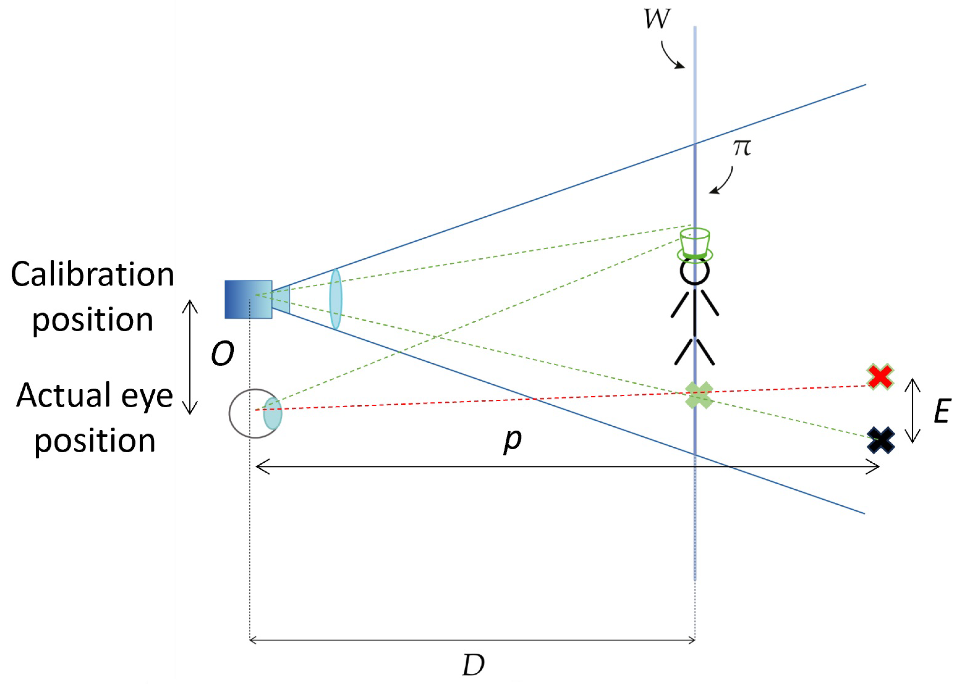
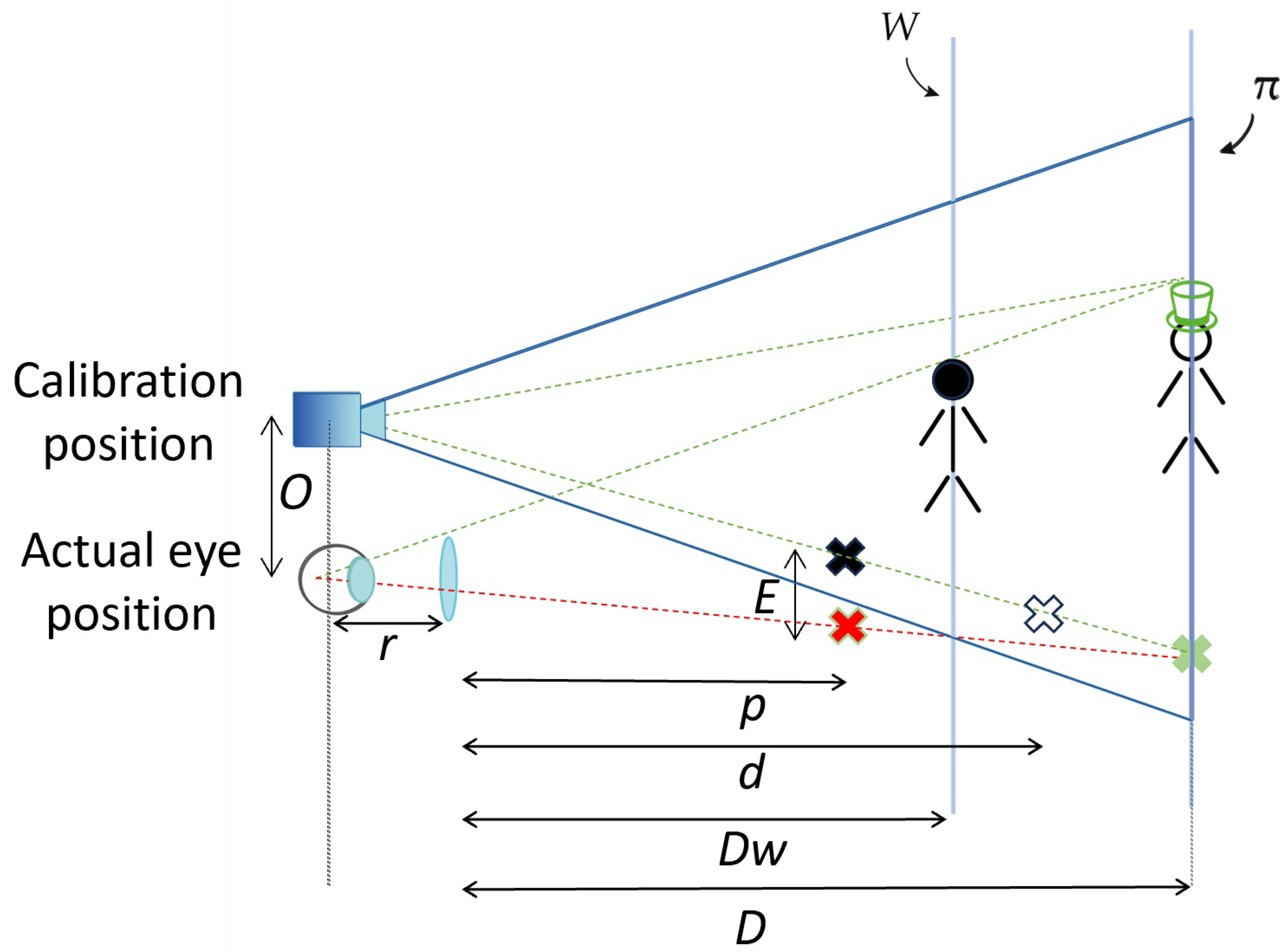
2. Appropriate Setting of the Display Focus Plane Distance

As described in the previous section, the most promising technological approach to implement an OST display devoid of any perceptual issue is the light field with a multifocal solution. The spacing between the focal planes should be quantified using optical rules and considering the entire range of viewing distances in front of the user. In the case of manual procedures, especially during precision tasks, the viewing distance range is limited by the arm length (600–700 mm) and as described in the following, a single focal plane with a proper distance can be enough. As described in Section 1.3 the eye-display pinhole model must be calibrated for any user’s eye position: the virtual rendering camera can then be parameterized through the obtained projection parameters to register the virtual content to the real scene. Yet, the hard part is to accurately determine the current position of the user’s eye nodal point. If the display is calibrated for an arbitrary calibration position [32], from which the virtual camera rendering generates the image displayed on the virtual focal plane, the off-set between the actual user’s eye position and the calibration position induces a parallax-related registration error (Figure 1), which could be compensated determining exactly such eye offset, for example with an eye-tracking camera.
As depicted in Figure 2, by adopting OST displays with an optical engine that collimates the virtual focal plane π at/close to the working distance D, we reduce the viewpoint parallax-related registration error provided that the range of working distances is not too far from the distance of the focal plane of the display.
This concept is geometrically detailed in [32], where it is also modeled the registration error E as a function of the radial viewpoint shift O with respect to the calibration position, the generic world point depth p, and the virtual focus plane distance D:
E = O p D 1
In a real implementation, the virtual information is not projected by the optics with a rigorous central projection and on a perfectly flat plane: each pixel is projected with a distorted projection angle, and it is focalized before or after the design plane [33]. The validation study performed in [32] confirms the validity of Equation (1). In OST displays, the eye-box, that is the spatial range where an eye can be located to see the entire display, is generally at most 8–10 mm in diameter. Calibrating the display in the center of the eye-box and considering a reasonable maximum eye offset O of 4 mm, based on Equation (1) the parallax error contribution remains lower than 1 mm for real points between 300 and 500 mm (p) if the OST display focal plane distance D is at 400 mm, as we already demonstrated in the experiments reported in [32]. In the same depth range, if we can guarantee a reasonable maximum eye offset O of 2 mm the error contribution becomes only 0.5 mm.
As reported in [34], simple optical rules allow us to quantify the depth of focus limits:
N e a r D O F = 1 1 p + Δ D O F
F a r D O F = 1 1 p Δ D O F
where ΔDOF is the depth of focus of the human eye expressed in diopters, which estimated mean value is 0.5 m 1 [35]. Given the same example of the display with the virtual image at distance D = 400 mm, the NearDOF is 333 mm and the FarDOF 500 mm. In this interval, both the virtual and the real information are perceived in focus, so devoid of any focus rivalry and vergence-accommodation conflict, with proper focus depth cues and a sub-millimetric registration error parallax contribution (in function of the maximum eye offset). In other words, for purposes of manual tasks guidance, and as a function of the required registration accuracy, the light field associated to the virtual information can be considered locationally compatible with the real one. As a general design rule, the OST display designers should therefore set the virtual focus plane distance considering the average working distance associated with the task for which the display is intended to be mostly used, and based on ergonomics requirements (e.g., for tasks performed while seated or stand-up). At the same time, the designers should also set the display depth range considering the accuracy required by the task (Equation (1)) and as a function of the depth of focus interval (Equations (2) and (3)).

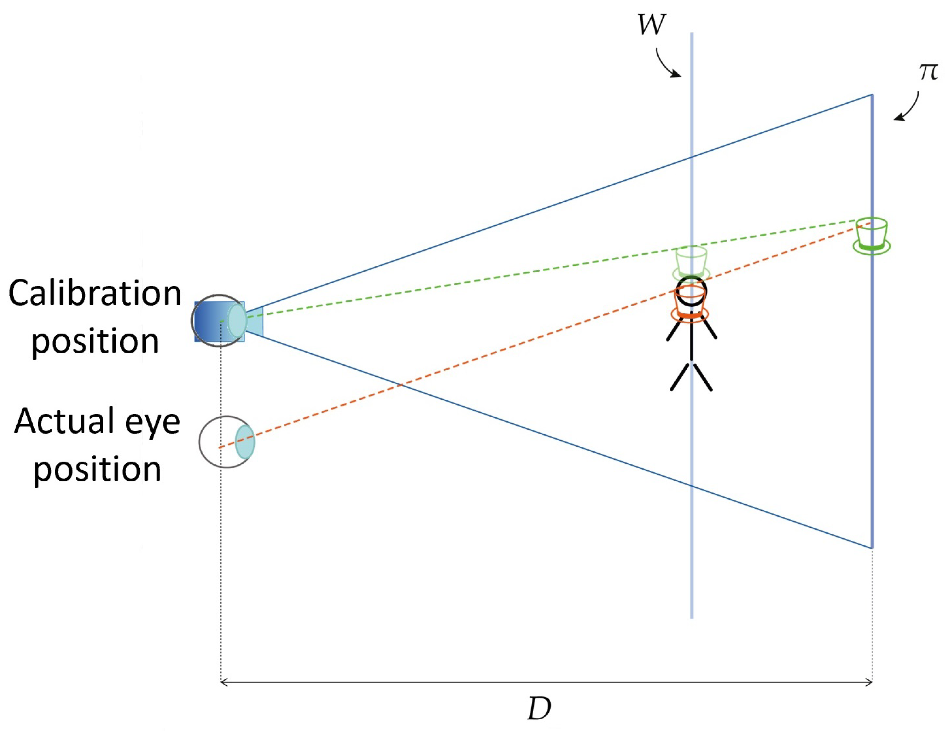
3. Additional Optics in Front of the OST Display

The approach described in the previous section requires a customization of the optics inside the display and furthermore it is not suitable for OST displays with an optical combiner consisting only in a waveguide, which requires a collimation optics that project the microdisplay image at infinite distance [36]. An alternative approach [37] is to add an ad-hoc lens in front of the OST display, to project the image of the real scene at the same distance as the virtual image. In Figure 3 this concept is depicted in the case of a waveguide-based OST dis-play with the additional optics consisting in a positive lens.
The focal length f of the additional lens can be set using the thin lens equation:
d = f p p f
where p is the distance between a point and the lens and d is the distance of the same point seen through the lens. Given Equation (4), to project points placed at the preferred design working distance Dw over the virtual image plane at distance D:
f = D w D D w + D
The virtual rendering camera must be properly parameterised through a dedicated calibration that encompasses the intrinsic parameters (linear and non-linear) of the OST display coupled, in this case, with the additional lens [35] to obtain a proper image registration of the virtual content to the real scene. Notably, the additional lens introduces a certain magnification (in the same way as viewing through a pair of ophthalmic glasses for presbyopia), which, during precision tasks, could represent itself an advantage. Also, in this case the offset O between the actual eye and calibration position induces a parallax-related registration error, which can be maintained under control in function of the task requirements using the following rules. In case of waveguide-based displays (with virtual focal plane at infinity, not as in Figure 3), the registration error E in function of the radial viewpoint shift O in respect to the calibration position, the generic world point depth p, the eye to lens distance r, and the preferred working distance Dw becomes [37]:
E = O ( p + r ) ( p D w ) p r D w ( p + r )
In case of negligible distance r in respect to the working distance, the equation can be approximated as:
E O p D w 1
Obtaining the same form valid for the case without the additional lens (Equation (1)), also sharing the same considerations about the magnitude of the registration error as a function of the eye offset O with respect to the calibration position. For example, also in this case, for a preferred working distance Dw of 400 mm the parallax contribution to the registration error remains under 1 mm in the range between 300 and 500 mm (p), with a maximum offset O of 4 mm, as we already demonstrated in the experiments reported in [37]. In this case, the virtual information remains on the display virtual focus plane at distance D, whereas the real information related to a point at distance p seen through the lens is moved at distance d (Equation (4)). For this reason, in case of a binocular implementation, the additional lens can introduce discomfort due to a vergence-accommodation conflict in the visualization of the real information, because the user’s eye accommodates the real world at distance d, and, at the same time, it is forced to converge to the distance of the real fixation point at distance p. Furthermore, points of at real world at distances over the magnifier focal distance (p > f) are optically formed not in front of the eye but behind the eye, and for this reason, they cannot be perfectly focused: the greater the distance of the object beyond the focal length of the magnifier, the greater the out of focus user view.
Table 1 reports a quick comparison of this solution with the previous solution described in Section 2.

4. Discussion and Conclusions

In case of OST displays to be used to guide manual surgical procedures, the designer should set the virtual focus plane distance based on strict ergonomics requirements associated with the task and define the working depth interval in function of the accuracy required by the task (1) and in function of the depth of focus. Depending on the task requirements, the virtual guidance information could be shown only in the working depth interval to guarantee the user performance. If a customization of the optics inside the display is not possible, an additional optics properly set in front of the display allows achieving the required registration accuracy in a predefined depth interval. This additional lens introduces focus distortions in the user’s real-world view that could compromise the correct execution of the task, even in the case of a perfect spatial AR registration. In both cases, a proper eye-display calibration for the calibration position is required and, especially in tasks requiring quick movements of the objects or of the head, the rendering frame rate and the entire rendering latency could introduce another dynamic source of registration error. Another technological point that could impact on the total registration error is the display angular resolution that spatially quantize the virtual information; this contribution is negligible in modern OST display with a number of pixels per degree close to 60, the maximum human visual acuity.

Author Contributions

Conceptualization, V.F., S.C. and F.C.; methodology, V.F., N.C. and F.C.; software, N.C. and F.C.; hardware N.C.; validation, V.F., N.C. and F.C.; resources, V.F.; writing—original draft preparation, V.F.; writing—review and editing, S.C., N.C. and F.C.; supervision, V.F.; project administration, V.F. All authors have read and agreed to the published version of the manuscript.

Funding

Work financed by the European Union -NextGenerationEU- with the POCARNO- AccuMixHolo project and by the Italian Ministry of Education and Research (MIUR) in the framework of the FoReLab project (Departments of Excellence).

Institutional Review Board Statement

Not applicable.

Informed Consent Statement

Not applicable.

Data Availability Statement

No new data were created.

Conflicts of Interest

The authors declare no conflict of interest.

Abbreviations

The following abbreviations are used in this manuscript:
ARAugmented Reality
HMDHead Mounted Display
OSTOptical See Through
VSTVideo See Through

References

  1. Abraham, M.; Annunziata, M. Augmented reality is already improving worker performance. Harv. Bus. Rev. 2017, 13, 1. [Google Scholar]
  2. Khakurel, J.; Melkas, H.; Porras, J. Tapping into the wearable device revolution in the work environment: A systematic review. Inf. Technol. People 2018, 31, 791–818. [Google Scholar] [CrossRef]
  3. Tang, A.; Owen, C.; Biocca, F.; Mou, W. Performance Evaluation of Augmented Reality for Directed Assembly. In Virtual and Augmented Reality Applications in Manufacturing; Ong, S.K., Nee, A.Y.C., Eds.; Springer: London, UK, 2004; pp. 311–331. [Google Scholar] [CrossRef]
  4. Shao, P.; Ding, H.; Wang, J.; Liu, P.; Ling, Q.; Chen, J.; Xu, J.; Zhang, S.; Xu, R. Designing a wearable navigation system for image-guided cancer resection surgery. Ann. Biomed. Eng. 2014, 42, 2228–2237. [Google Scholar] [CrossRef] [PubMed]
  5. Muensterer, O.J.; Lacher, M.; Zoeller, C.; Bronstein, M.; Kübler, J. Google Glass in pediatric surgery: An exploratory study. Int. J. Surg. 2014, 12, 281–289. [Google Scholar] [CrossRef] [PubMed]
  6. Carbone, M.; Cutolo, F.; Condino, S.; Cercenelli, L.; D’Amato, R.; Badiali, G.; Ferrari, V. Architecture of a Hybrid Video/Optical See-through Head-Mounted Display-Based Augmented Reality Surgical Navigation Platform. Information 2022, 13, 81. [Google Scholar] [CrossRef]
  7. Cheng, D.; Wang, Q.; Liu, Y.; Chen, H.; Ni, D.; Wang, X.; Yao, C.; Hou, Q.; Hou, W.; Luo, G.; et al. Design and manufacture AR head-mounted displays: A review and outlook. Light. Adv. Manuf. 2021, 2, 350–369. [Google Scholar] [CrossRef]
  8. Rolland, J.P.; Cakmakci, O. The past, present, and future of head-mounted display designs. In Optical Design and Testing II; Wang, Y., Weng, Z., Ye, S., Sasian, J.M., Eds.; International Society for Optics and Photonics; SPIE: Bellingham, WA, USA, 2005; Volume 5638, pp. 368–377. [Google Scholar]
  9. Holliman, N.S.; Dodgson, N.A.; Favalora, G.E.; Lachlan, P. Three-Dimensional Displays: A Review and Applications Analysis. IEEE Trans. Broadcast. 2011, 57, 362–371. [Google Scholar] [CrossRef]
  10. Cheng, D.; Duan, J.; Chen, H.; Wang, H.; Li, D.; Wang, Q.; Hou, Q.; Yang, T.; Hou, W.; Wang, D.; et al. Freeform OST-HMD system with large exit pupil diameter and vision correction capability. Photonics Res. 2022, 10, 21–32. [Google Scholar] [CrossRef]
  11. Birlo, M.; Edwards, P.E.; Clarkson, M.; Stoyanov, D. Utility of optical see-through head mounted displays in augmented reality-assisted surgery: A systematic review. Med. Image Anal. 2022, 77, 102361. [Google Scholar] [CrossRef]
  12. Doughty, M.; Ghugre, N.R.; Wright, G.A. Augmenting performance: A systematic review of optical see-through head-mounted displays in surgery. J. Imaging 2022, 8, 203. [Google Scholar] [CrossRef]
  13. Insight into vergence-accommodation mismatch. Proc. SPIE. 2013, 5, 8735.
  14. Kramida, G. Resolving the Vergence-Accommodation Conflict in Head-Mounted Displays. IEEE Trans. Vis. Comput. Graph. 2016, 22, 1912–1931. [Google Scholar] [CrossRef] [PubMed]
  15. Condino, S.; Carbone, M.; Piazza, R.; Ferrari, M.; Ferrari, V. Perceptual Limits of Optical See-Through Visors for Augmented Reality Guidance of Manual Tasks. IEEE Trans. Biomed. Eng. 2020, 67, 411–419. [Google Scholar] [CrossRef] [PubMed]
  16. Ware, C. Information Visualization: Perception for Design; Morgan Kaufmann: Burlington, MA, USA, 2013. [Google Scholar]
  17. Sielhorst, T.; Feuerstein, M.; Navab, N. Advanced Medical Displays: A Literature Review of Augmented Reality. J. Disp. Technol. 2008, 4, 451–467. [Google Scholar] [CrossRef]
  18. Watt, S.J.; Akeley, K.; Ernst, M.O.; Banks, M.S. Focus cues affect perceived depth. J. Vis. 2005, 5, 834–862. [Google Scholar] [CrossRef] [PubMed]
  19. Condino, S.; Turini, G.; Parchi, P.D.; Viglialoro, R.M.; Piolanti, N.; Gesi, M.; Ferrari, M.; Ferrari, V. How to Build a Patient-Specific Hybrid Simulator for Orthopaedic Open Surgery: Benefits and Limits of Mixed-Reality Using the Microsoft HoloLens. J. Healthc. Eng. 2018, 2018, 5435097. [Google Scholar] [CrossRef] [PubMed]
  20. Grubert, J.; Itoh, Y.; Moser, K.; Swan, J.E. A Survey of Calibration Methods for Optical See-Through Head-Mounted Displays. IEEE Trans. Vis. Comput. Graph. 2018, 24, 2649–2662. [Google Scholar] [CrossRef]
  21. Plopski, A.; Itoh, Y.; Nitschke, C.; Kiyokawa, K.; Klinker, G.; Takemura, H. Corneal-Imaging Calibration for Optical See-Through Head-Mounted Displays. IEEE Trans. Vis. Comput. Graph. 2015, 21, 481–490. [Google Scholar] [CrossRef]
  22. Itoh, Y.; Klinker, G. Performance and sensitivity analysis of INDICA: INteraction-Free DIsplay CAlibration for Optical See-Through Head-Mounted Displays. In Proceedings of the 2014 IEEE International Symposium on Mixed and Augmented Reality (ISMAR), Munich, Germany, 10–12 September 2014; pp. 171–176. [Google Scholar] [CrossRef]
  23. Itoh, Y.; Klinker, G. Interaction-free calibration for optical see-through head-mounted displays based on 3D Eye localization. In Proceedings of the 2014 IEEE Symposium on 3D User Interfaces (3DUI), Minneapolis, MN, USA, 29–30 March 2014; pp. 75–82. [Google Scholar] [CrossRef]
  24. Levoy, M. Light Fields and Computational Imaging. Computer 2006, 39, 46–55. [Google Scholar] [CrossRef]
  25. Huang, H.; Hua, H. Systematic characterization and optimization of 3D light field displays. Opt. Express 2017, 25, 18508–18525. [Google Scholar] [CrossRef]
  26. Hua, H.; Javidi, B. A 3D integral imaging optical see-through head-mounted display. Opt. Express 2014, 22, 13484–13491. [Google Scholar] [CrossRef] [PubMed]
  27. Ferrari, V.; Calabrò, E.M. Wearable light field optical see-through display to avoid user dependent calibrations: A feasibility study. In Proceedings of the 2016 SAI Computing Conference (SAI), London, UK, 13–15 July 2016; pp. 1211–1216. [Google Scholar]
  28. Kiyokawa, K.; Billinghurst, M.; Campbell, B.; Woods, E. An occlusion capable optical see-through head mount display for supporting co-located collaboration. In Proceedings of the Second IEEE and ACM International Symposium on Mixed and Augmented Reality, Tokyo, Japan, 10 October 2003; pp. 133–141. [Google Scholar]
  29. Maimone, A.; Fuchs, H. Computational augmented reality eyeglasses. In Proceedings of the 2013 IEEE International Symposium on Mixed and Augmented Reality (ISMAR), Adelaide, Australia, 1–4 October 2013; pp. 29–38. [Google Scholar]
  30. Zhan, T.; Xiong, J.; Zou, J.; Wu, S.T. Multifocal displays: Review and prospect. PhotoniX 2020, 1, 10. [Google Scholar] [CrossRef]
  31. Wann, J.P.; Rushton, S.; Mon-Williams, M. Natural problems for stereoscopic depth perception in virtual environments. Vis. Res. 1995, 35, 2731–2736. [Google Scholar] [CrossRef] [PubMed]
  32. Cutolo, F.; Cattari, N.; Fontana, U.; Ferrari, V. Optical See-Through Head-Mounted Displays With Short Focal Distance: Conditions for Mitigating Parallax-Related Registration Error. Front. Robot. AI 2020, 7, 572001. [Google Scholar] [CrossRef]
  33. Klemm, M.; Seebacher, F.; Hoppe, H. High accuracy pixel-wise spatial calibration of optical see-through glasses. Comput. Graph. 2017, 64, 51–61. [Google Scholar] [CrossRef]
  34. Condino, S.; Cutolo, F.; Zari, G.; D’Amato, R.; Carbone, M.; Vincenzo, F. How to Mitigate Perceptual Limits of OST Display for Guiding Manual Tasks: A Proof of Concept Study with Microsoft HoloLens. In Proceedings of the 2022 IEEE International Conference on Metrology for Extended Reality, Artificial Intelligence and Neural Engineering (MetroXRAINE), Rome, Italy, 26–28 October 2022; pp. 506–510. [Google Scholar]
  35. Wang, B.; Ciuffreda, K.J. Depth-of-Focus of the Human Eye: Theory and Clinical Implications. Surv. Ophthalmol. 2006, 51, 75–85. [Google Scholar] [CrossRef]
  36. Kress, B.C. Optical Architectures for Augmented-, Virtual-, and Mixed-Reality Headsets; SPIE: Bellingham, WA, USA, 2020. [Google Scholar]
  37. Ferrari, V.; Cattari, N.; Fontana, U.; Cutolo, F. Parallax Free Registration for Augmented Reality Optical See-Through Displays in the Peripersonal Space. IEEE Trans. Vis. Comput. Graph. 2022, 28, 1608–1618. [Google Scholar] [CrossRef]
Figure 1. Parallax-induced augmented reality misalignment: for simplicity we can consider the real 3D information that lies on the plane W while the virtual information lies on the focal plane π ; if the eye is positioned exactly at calibration position the virtual (green) information appears registered with the real (black) one, otherwise the user can perceive a misalignment (highlighted in red).
Mti 08 00004 g001
Figure 2. An HMD with the appropriate setting of the display focus plane distance at/close to the working distance mitigates the parallax-induced misalignment. If the real (black) information is not at the optimal design distance D the virtual (green) information appears misaligned (in red) (if the eye is not exactly at the calibration position).
Mti 08 00004 g002
Figure 3. Solution with an additional optics in front of the OST display. The positive lens in front of the OST display projects the image of the real information -placed at the optimal design distance Dw- to the virtual focal plane π to guarantee the registration even if the eye is not at the calibration position. If the real (black) information is not at the design working distance Dw its image will not be on the virtual focal plane and the virtual (green) information will appear misaligned (in red) (if the eye is not exactly at the calibration position).
Mti 08 00004 g003
Table 1. A comparison between the solution consisting in an appropriate setting of the display focus plane distance with the additional optics in front of the OST display.
Display with an Appropriate Focus
Plane Distance
Additional Optics in Front of the Display
Parallax-related registration errorAvoided at the optimal design working distance, significantly mitigated in the surrounding area (Equation (1))Avoided at the optimal design working distance, significantly mitigated in the surrounding area (Equation (7))
Focus rivalryAvoided in a useful working distance range (Equations (2) and (3))Avoided in a useful working distance range
Vergence-accommodation conflictAvoided in a useful working distance range (Equations (2) and (3))Can be an issue
Wave guide display with infinite
focal plane
Not feasibleFeasible
Disclaimer/Publisher’s Note: The statements, opinions and data contained in all publications are solely those of the individual author(s) and contributor(s) and not of MDPI and/or the editor(s). MDPI and/or the editor(s) disclaim responsibility for any injury to people or property resulting from any ideas, methods, instructions or products referred to in the content.

