Review

Optimal Stimulus Properties for Steady-State Visually Evoked Potential Brain–Computer Interfaces: A Scoping Review

Electrical Engineering and Computer Science, York University, North York, ON M3J 1P3, Canada
*
Author to whom correspondence should be addressed.
Multimodal Technol. Interact. 2024, 8(2), 6; https://doi.org/10.3390/mti8020006
Submission received: 16 December 2023 / Revised: 15 January 2024 / Accepted: 19 January 2024 / Published: 24 January 2024

Abstract

:
Brain–computer interfaces (BCIs) based on steady-state visually evoked potentials (SSVEPs) have been well researched due to their easy system configuration, little or no user training and high information transfer rates. To elicit an SSVEP, a repetitive visual stimulus (RVS) is presented to the user. The properties of this RVS (e.g., frequency, luminance) have a significant influence on the BCI performance and user comfort. Several studies in this area in the last one-and-half decades have focused on evaluating different stimulus parameters (i.e., properties). However, there is little research on the synthesis of the existing studies, as the last review on the subject was published in 2010. Consequently, we conducted a scoping review of related studies on the influence of stimulus parameters on SSVEP response and user comfort, analyzed them and summarized the findings considering the physiological and neurological processes associated with BCI performance. In the review, we found that stimulus type, frequency, color contrast, luminance contrast and size/shape of the retinal image are the most important stimulus properties that influence SSVEP response. Regarding stimulus type, frequency and luminance, there is a trade-off between the best SSVEP response quality and visual comfort. Finally, since there is no unified measuring method for visual comfort and a lack of differentiation in the high-frequency band, we proposed a measuring method and a division of the band. In summary, the review highlights which stimulus properties are important to consider when designing SSVEP BCIs. It can be used as a reference point for future research in BCI, as it will help researchers to optimize the design of their SSVEP stimuli.

1. Introduction

The term brain–computer-interface (BCI) was firstly coined in 1973 by Jacques J. Vidal, who described it as “utilizing the brain signals in a [hum]man-computer dialogue” [1,2] (p. 157f). A BCI is therefore a communication system, in which the user’s intentions are communicated without the brain’s normal output pathways, such as peripheral nerves and muscles [3]. This makes this type of interface relevant to users with reduced motor abilities. After Vidal coined the term BCI, the research field stayed dormant in the 1970s and early 1980s. Then, in the late 1980s and 1990s, researchers pioneered the field with new concepts and applications such as the P300 and steady-state visually evoked potentials (SSVEPs). P300 is a paradigm which describes event-related potentials (ERP) that are elicited approximately 300 ms after a stimulus is presented. Around the year 2000, BCI became a research field on its own with new research teams joining and starting a drastic expansion in size and scope in the following years [1]. With that expansion, several new paradigms and applications followed. Regarding SSVEP BCI, various application fields for impaired and non-impaired users now exist, including assistive technologies, (remote) control of vehicles, Internet of Things and virtual reality applications [4].
A BCI consists of a hardware component that captures brain signals and translates them into commands that can be executed by a computer. This hardware can be invasive or non-invasive. Invasive techniques, such as electrocorticography (ECoG) [5], allow a high-quality data acquisition but require surgical operations asscoiated with medical risks. Therefore, non-invasive techniques, such as functional magnetic resonance imaging (fMRI) [6], functional near-infrared spectroscopy (fNIRS) [7], magnetoencephalography (MEG) [8] or electroencephalography (EEG) [9], are used in most BCI research and applications. Among these techniques, EEG is the most popular and widely used due to its portability, ease of use, high number of brainwave channels and affordability [4]. In general, three types of BCI exist. They include the following [10]:
  • Active BCI, where the user actively generates the brain signals that should be classified, for example, using motor imagery (MI). These are usually based on event-related synchronization/desynchronization (ERS/ERD).
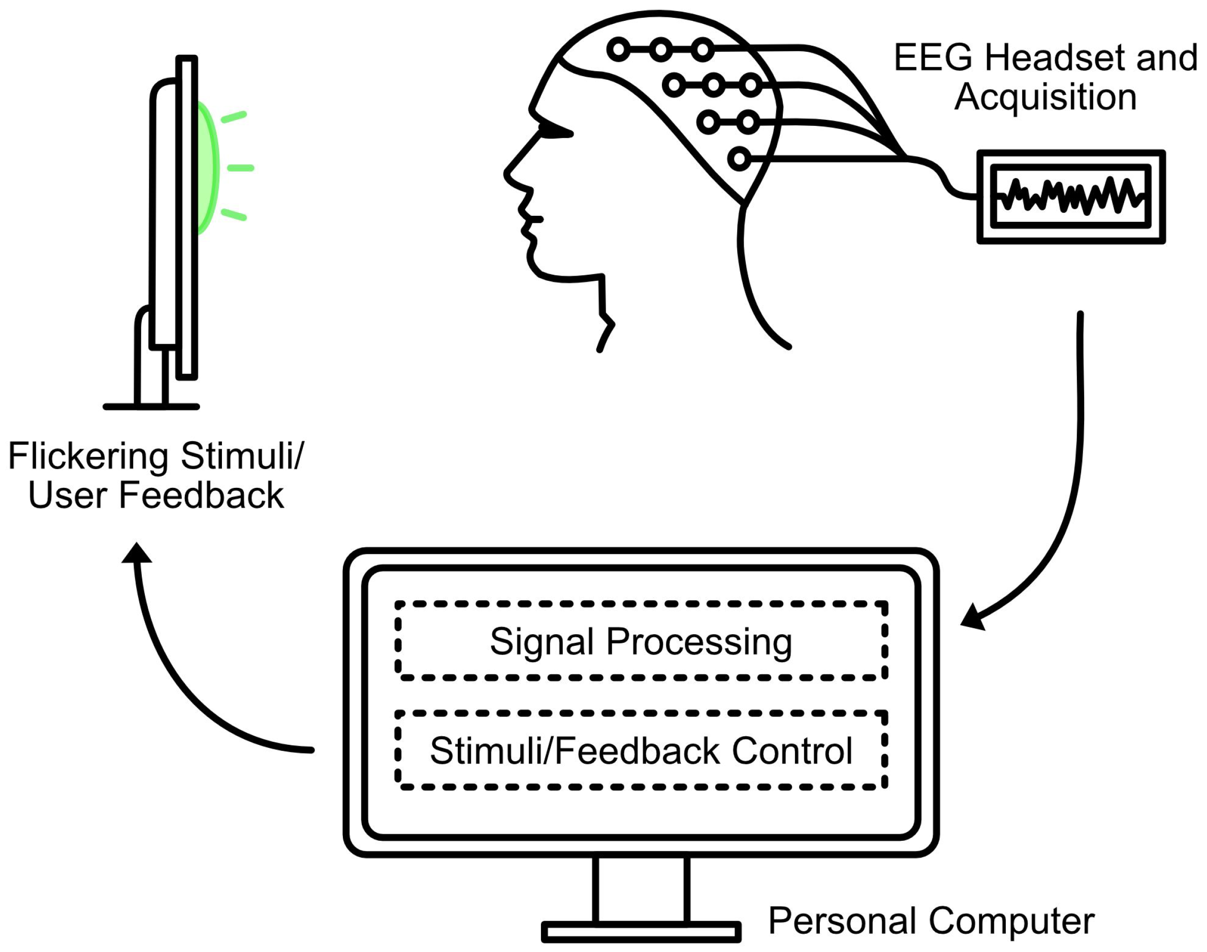
  • Reactive BCI, where a stimulus is presented and the user’s response signal is measured. These signal responses can be, for example, visually evoked potentials (VEPs), steady-state visually evoked potentials (SSVEPs), which are evoked by looking at specific frequencies, or P300 waves, which are event-related potentials stimulated in the process of decision making.
  • Passive BCI, where no effort on the part of the user is required. In this type of BCI, the mental state of the user is monitored automatically, for example, whether the mental state is in attention or relaxation mode.
SSVEP-based BCI has the advantage of an easy system configuration, little or no user training, and high information transfer rates [11]. In this type of BCI, one or more repetitive visual stimuli (RVS) are presented during a distinctive frequency and phase. The user can select a stimulus by visually focusing on it. This evokes an SSVEP response in the brain that can then be detected and classified through a series of signal processing steps [12]. Figure 1 shows the general structure of an SSVEP BCI.
To investigate the quality of an SSVEP BCI, the SSVEP response is first visualized by the power of spectral density (PSD) and the signal-to-noise ratio (SNR). Next, the classification accuracy, classification speed and the number of available targets are calculated. The accuracy is mainly influenced by the SSVEP response and the SNR. The speed depends on the time it takes for the SSVEP to be of satisfactory strength. The number of targets defines the number of possible commands and can have an influence on the accuracy and speed [12].
All these variables can be combined by the information transfer rate (ITR), which describes the amount of information transferred per unit of time (usually minutes):
I T R = s × log 2 N + P × log 2 P + ( 1 P ) × log 2 1 P N 1
Therefore, the ITR includes s, the number of detections per minute (speed), N, the number of possible selections (targets) and P, the probability that the desired selection will actually be detected (accuracy) [13].
Aside from these performance measures, visual comfort and fatigue (i.e., user comfort) should be taken into account. This is especially important, since, depending on luminance or chromaticity, flickering stimuli can cause epileptic responses [14]. The user comfort is mostly measured by a Likert scale that evaluates visual comfort, visual fatigue, flickering feeling or similar attributes [15,16,17,18,19].
Aside from other components, such as the recording device or the evaluation algorithm, the properties of the RVS in an SSVEP BCI have a major influence on the performance, the user comfort and safety [13]. Zhu et al. published a review in 2010 that focused on the SSVEP BCI performance in relation to the stimulus type, frequency and color [12]. However, since then, there has been a lot of research on the stimulus parameters for SSVEP BCI. In recent times, several additional factors, aside stimulus type, frequency and color, have been identified to have influence on the BCI quality. However, this research and the findings are yet to be synthesized and summarized to date. To bridge this gap in the existing literature, a scoping review was conducted in order to summarize the work on stimulus parameters that have a significant influence on the performance/user comfort and uncover their ideal configurations. The goal of this scoping review is to identify gaps in the existing body of knowledge and help future researchers and practitioners to optimize their stimulus selection. To accomplish this goal, the following research questions were formulated:
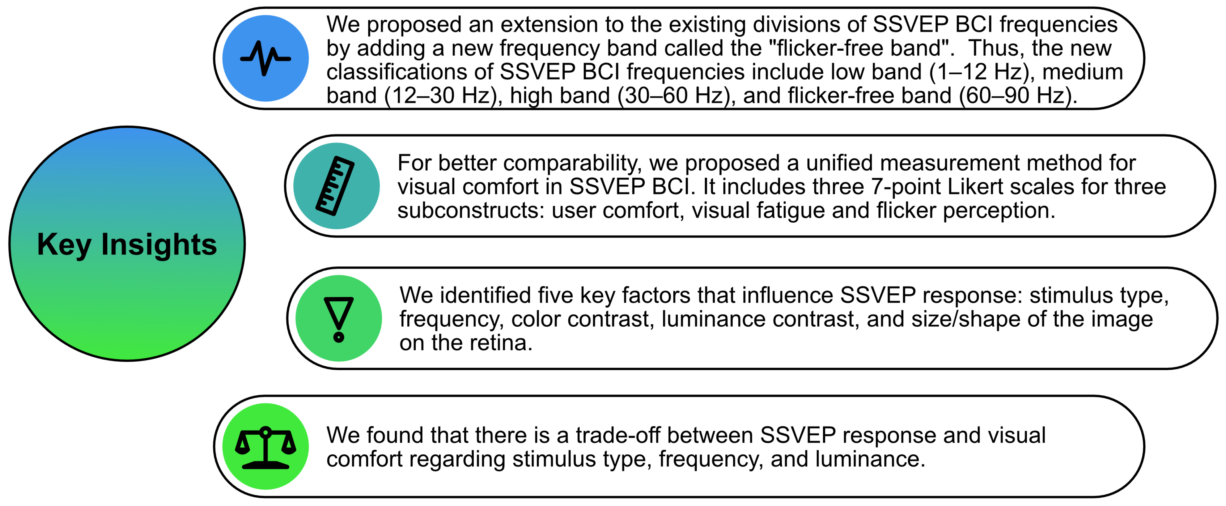
  • Which parameters, based on the literature, have an influence on SSVEP BCI performance?
  • What are the optimal configurations of the parameters?
This paper is organized as follows. In Section 2, the methods of the scoping review are described. Section 3 outlines the quantitative results and Section 4 shows the qualitative results of the review. Finally, in Section 5, the results are discussed.

2. Materials and Methods

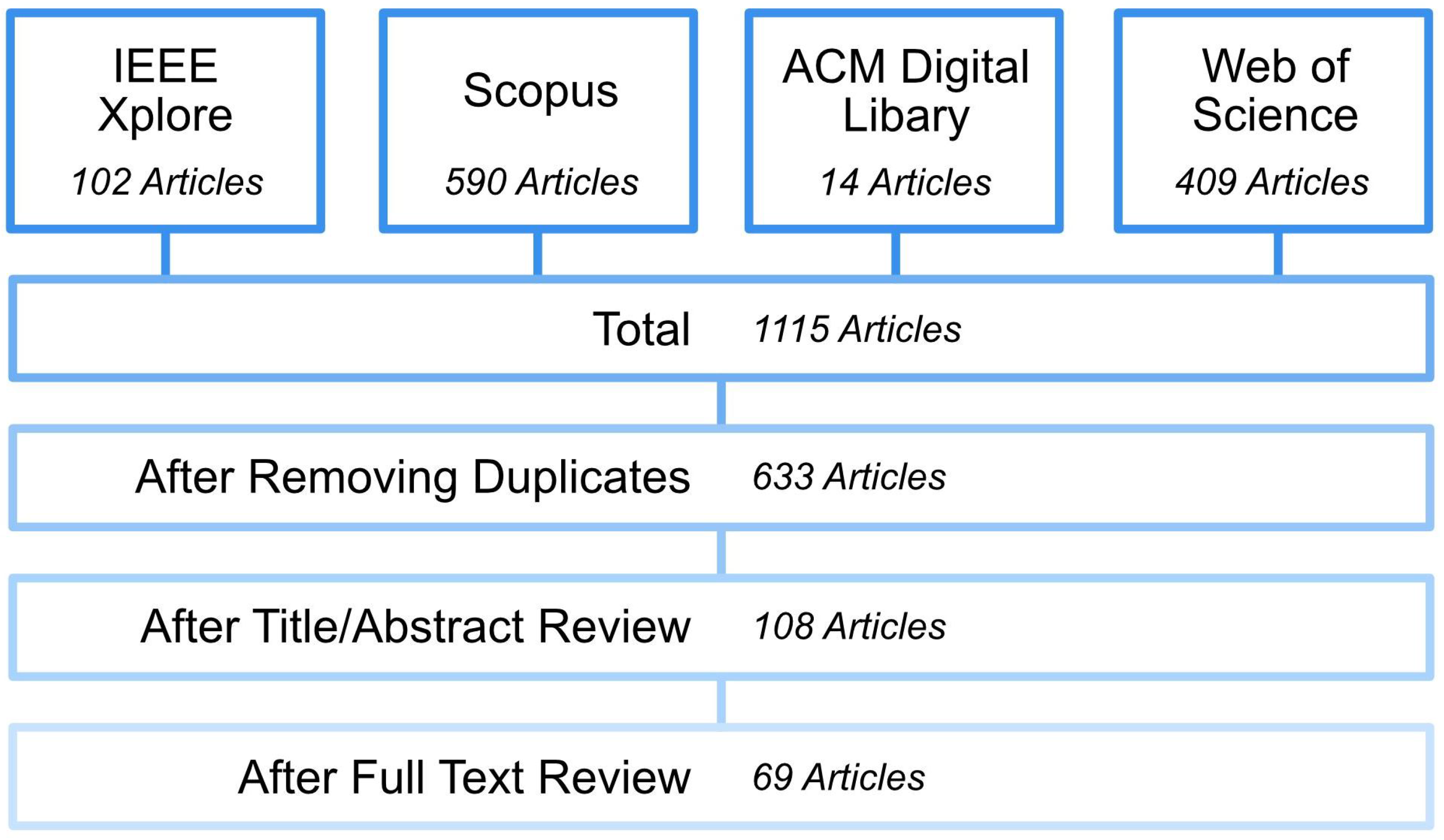
Literature Search and Inclusion Criteria

For the scoping review to summarize the work on the stimulus parameters for SSVEP BCI, the following databases were searched: IEEE Xplore, Scopus, ACM Digital Library and Web of Science. Both authors defined and refined the search string used for the database search. The exact search strings and filters can be found in Appendix A. Papers were included in the review if at least one term from each of the following three sets was found in their title, abstract or keywords: (1) Brain-Computer-Interface*, Brain Computer Interface*, BCI, Brain–Machine-Interface*, Brain Machine Interface*, BMI (2) Steady-State Visually Evoked Potential*, SSVEP, Steady-State Visually Evoked Respons*, SSVER (3) Stimul*. The asterisk matches any combination of letters (e.g., “s”, “us”, “i”, “ation”).
To be included in the review, an article must implement a repetitive visual stimulus for an SSVEP BCI and its main focus must be on the evaluation with users. Articles that only focused on inter-stimulus proximity or the number of stimulus targets were excluded, as long as they focused on the interplay between different stimuli and not on their attributes. Also, only peer-reviewed journal articles written in English, based on primary data and published prior to September 2023 were considered.
The screening and selection of the included articles were executed by the first author with inputs from the second author. The database search resulted in 1113 papers, out of which 633 were left after removing the duplicates. These articles were screened based on the inclusion/exclusion criteria by reading their titles and abstracts, which resulted in 108 papers. Six of these papers were not accessible. For the remaining 102 papers, a full-text review was conducted. After the review, 33 papers were excluded, resulting in a total number of 69 articles for the final review and analysis. An overview of the literature search strategy is shown in Figure 2.

3. Quantitative Results

3.1. Proposals vs. Evaluations

Sixty-nine papers met the inclusion criteria. Fifty of them evaluated the different stimulus setups with regard to one or several factors to decide which configuration for that factor was preferable. The other 19 papers proposed new stimulus setups and checked their feasibility by reporting some performance measures like accuracy or ITR.

3.2. BCI and Experimental Setups

3.2.1. Number of Targets

The number of targets is an important factor to consider when it comes to the design of a BCI. A higher number increases the number of possible commands, but it can also have a negative influence on the accuracy of the system.
Among the included papers, 20 of them used only one target and 18 used four targets—the second most used number. Only eight papers used more than nine targets with a maximum of 40 targets [20]. A complete overview on the number of targets can be found in Table 1.

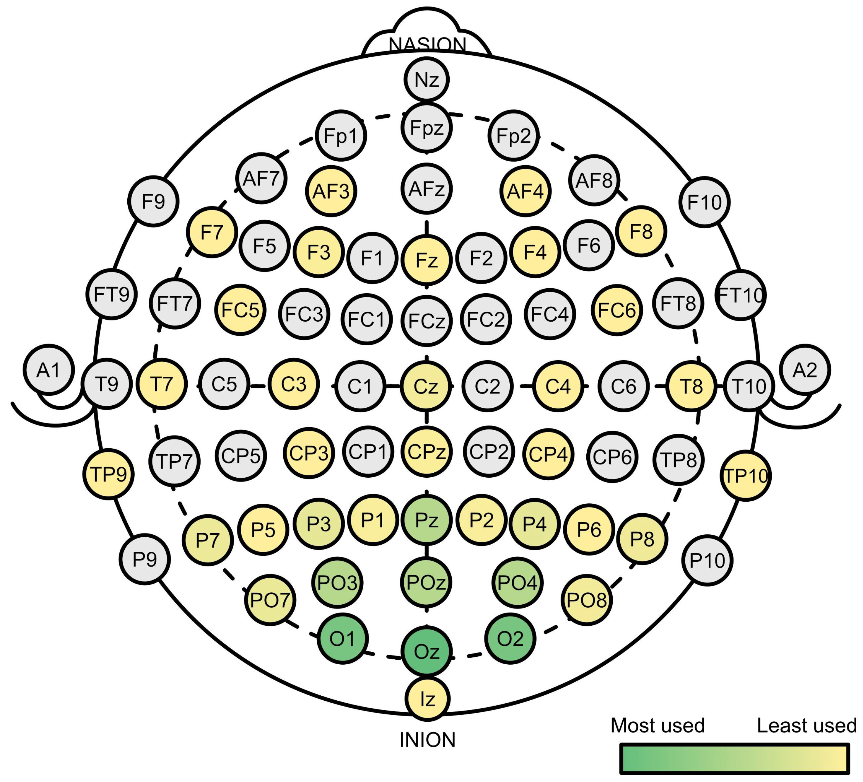
3.2.2. Electrodes Used for Evaluation

Regarding the hardware component used to measure brain activity, all reviewed papers used EEG and placed the electrodes according to the international 10–20 system or a subsystem of it. Four papers did not report which specific electrodes they used for the evaluation, but only reported the total number of electrodes. The other articles reported the total number of electrodes measured and the subsets of electrodes they used for the evaluation in their experiment.
Fifty-six papers used less than 10 electrodes for their evaluation (excluding the reference electrode). Nine electrodes was the number that was used most often by 10 articles, closely followed by one and three electrodes, which were used by nine articles each (also excluding the reference electrode).
The electrode positions that were used most often were the electrodes on the occipital lobe Oz, O1 and O2, which were used in 58, 51 and 51 studies, respectively. The electrodes PO3, POz, PO4 and Pz on the parietal lobe were also used quite often, with 29, 28, 27 and 25 usages, respectively. A heat map of the used electrodes is shown in Figure 3.

3.2.3. Participants

Regarding study participants, most papers had at least one of the two eligibility criteria: (1) the participant has normal or corrected to normal vision; (2) the participant does not have a history of epilepsy.
Fifty-eight of the papers reported only one number of participants, while the other 11 papers had different experiments with varying numbers of participants. From all articles, 62 reported a number of participants that was lower than 21 for at least one of their experiments. The most common numbers of subjects were 10, reported in 15 papers, and 12, reported in 13. The highest number of participants was 42, reported in two papers.

3.3. Dependent Variables

Overall, the papers used the common evaluation variables for BCI. The classification accuracy was the most used, by 46 papers, followed by the SSVEP-Response or Spectral Density, which was reported by 35 papers. Thirty-one papers reported the ITR and twenty-six reported the SNR.
The user comfort was evaluated in various ways by 40 papers, but no standard way to measure could be observed. Variables that were measured include the user/visual/stimulation comfort, preference, (flicker) perception, (visual) fatigue, user experience, visual irritation and usability. These variables were mostly measured with a short question (e.g., How much do you like this stimulation? [66]) on a Likert scale. Some papers also used questionnaires such as the NASATLX [83] or the UEQ [84].
In cases of special experimental setups or investigation goals, a few papers also used additional dependent variables such as task completion time or typing speed.
Most of the variables, including accuracy and ITR, are not solely dependent on the stimulus parameters but also on other factors, such as the classification algorithm. In addition, there is no standard measurement instrument for the visual comfort. Due to these limitations, an evaluation of the stimulus parameters between papers based on these variables, would not be valid. Therefore, in the following section, the results from each paper will be reported without a comparison of their dependent variables.

3.4. Stimuli Categorization

In their review, Zhu et al. classified the repetitive visual stimuli into three categories: light, single graphic and pattern reversal [12]. This categorization is not really selective. For example, one could argue that a black–white flickering square, categorized as single graphic, is the same as a 1 × 1 pattern reversing checkerboard, which would then be categorized as pattern reversal. Or it can be argued that there is not a huge difference in the stimulus between the light and single-graphic categories except the device. Since newer stimuli and devices have been and are being developed, this categorization is not up-to-date anymore. Therefore, a new categorization is proposed based on the two factors: stimulus type and device.

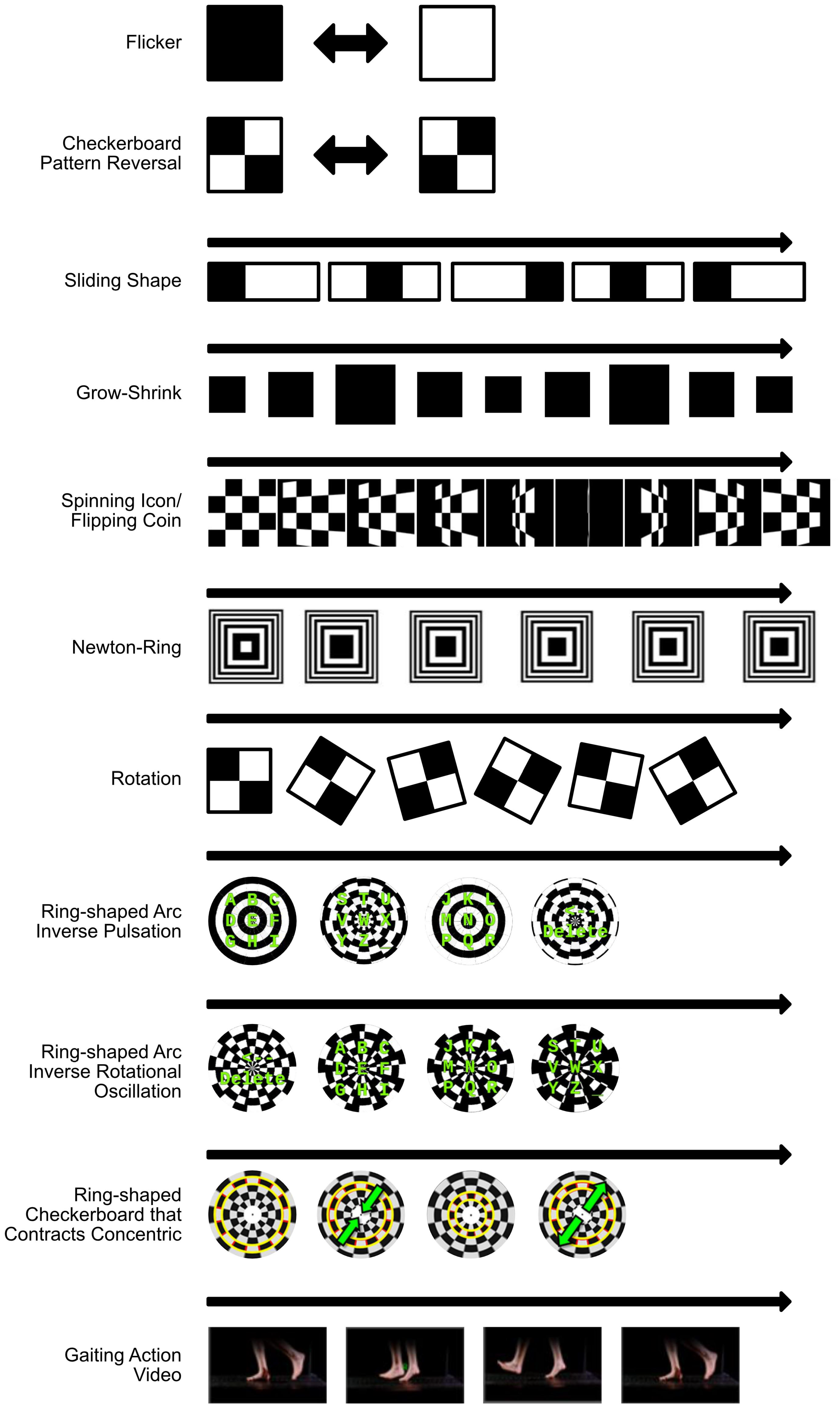
3.4.1. Stimulus Type

All stimulus types used can be classified as pattern-reversal stimuli, since after a certain amount of time, the stimulus was repetitive. The stimulus types can be divided into two main categories: (1) Those that use flicker, so a fixed area (e.g., pixels on an LCD screen) changes its luminance or color; (2) Those that use motion, so the area, in which luminance and color changes, are not fixed (e.g., a moving box). Some stimuli also combine both characteristics.
Among the analyzed papers, 66 implemented at least one flickering stimulus. This number includes 16 articles that implemented a pattern-reversal checkerboard, which is a special type of flickering stimulus. The specialty of the checkerboard is that the transition from an OFF to an ON state (e.g., black-to-white) happens twice a cycle.
Twelve papers implemented at least one motion stimulus and four papers implemented a combined motion and flickering stimulus. The total number exceeds 69, since some papers implemented more than one stimulus type.

3.4.2. Device

Device is the second factor based on which visual stimuli can be categorized. In terms of BCI applications, the choice of device is often guided by the context of use since it puts physical limits, e.g., the portability or viewing distance, on it. But also, the stimulus design is affected by the type of device. For example, the refresh rate of a screen limits the frequencies that can be created with it to be the integer divisors of the rate [79]. A phase-approaching stimulation to also create frequencies that are not integer divisors is possible. However, it results in a worse but still acceptable SSVEP response, accuracy, and ITR [68]. From the review, three major categories of devices emerge: (1) light-emitting diodes (LEDs); (2) screens (liquid–crystal displays—LCD, cathode-ray tube—CRT, hybrids); (3) augmented and virtual reality (AR/VR) displays such as head-up displays or head-mounted displays (HMD).
Out of the 69 analyzed papers, 16 used LEDs as stimulation devices. These papers are charted in Table A1. Screens were used by 48 articles. These screens were liquid–crystal displays (LCD) in 43, cathode-ray tube screens (CRT) in three, and LED–LCD hybrids in two cases. One paper just referred to the device as a “screen”. The articles that used screens are listed in Table A2. AR and VR displays were used by 12 papers, among which 8 were head-mounted AR glasses, 3 were head-mounted VR glasses, and 1 was a head-up display. These papers are listed in Table A3. A summation of the reported number exceeds 69, the number of analyzed papers, since some papers used multiple device types.

4. Qualitative Results

4.1. Evaluated Stimuli Factors

In their review, Zhu et al. evaluated the stimuli according to the rendering devices, stimulation frequencies and colors aside from the stimulus type [12]. Ng et al. stated that the stimulus temporal frequency, spatial size, number of simultaneously displayed stimuli and their spatial proximity are the four minimum variables to consider when setting up an SSVEP BCI visual stimulus [49]. Since the papers on inter-stimulus proximity or the number of stimuli were excluded from the review, the following stimulus factors were evaluated by the reviewed papers: (1) stimulus type; (2) device; (3) frequency; (4) wave parameters; (5) luminance; (6) color; (7) size and shape; (8) viewing distance; (9) dimensions; and (10) fixation point.

4.1.1. Stimulus Type

Apart from the classic flickering or pattern-reversal checkerboard stimuli, several motion stimulus types have been used and proven to work. These include a sliding shape that moves every iteration [51,55], a grow–shrink stimulus [15,16,54,66], a Newton ring stimulus [66], a spinning icon/flipping coin [55,77], a rotation stimulus [44,73], a ring-shaped arc inverse pulsation [55], a ring-shaped arc inverse rotational oscillation [55], a ring-shaped checkerboard that contracts concentric [20], and a gaiting action video [53]. A visual overview of the different stimulus types can be found in Figure 4.
Some of the papers compared different stimulus types. Regarding the flickering stimuli, Peguero et al. showed that the on–off flickering stimulus is superior to pattern-reversal checkerboard in terms of power response except that it has less visual comfort [62].
Comparatively, the flickering stimulus outperformed the motion stimulus in terms of accuracy and ITR [53,55,66]. In terms of comfort, the flickering stimulus produced significantly lower values than the grow–shrink and Newton ring stimuli [66]. The work by Stawicki and Volosyak showed no significant difference in comfort between flickering and motion stimuli [55].
Among the motion stimuli, grow–shrink gave better accuracy than the Newton ring stimulus [66]. The sliding shape (circle) and flipping coin stimuli had a significantly higher ITR than the checkerboard pulsation, arc inverse pulsation and arc inverse rotational oscillation [55]. Chai et al. reported that the grow–shrink was more comfortable than the Newton ring stimulus [66], while Stawicki and Volosyak found no significant difference in the comfort between sliding shape (circle), flipping coin, ring-shaped checkerboard, arc inverse pulsation and arc inverse rotational oscillation stimuli [55].
In AR, the grow–shrink stimulus had better accuracy than the flicker and significantly higher accuracy than a checkerboard pattern-reversal stimulus [54]. In contrast to this, Zehra et al. reported no significant difference, with the grow–shrink stimulus performing worse [16]. In VR, Choi et al. found that the stimulus type that is rated as more comfortable generally outperforms others. In their experiment, the grow–shrink stimulus achieved better classification accuracy than a checkerboard stimulus [15].
Some articles combined both motion and flickering in their stimulus. It was shown that a combination of grow–shrink and flicker or rotation and flicker can achieve an acceptable SSVEP response and accuracy (>90%) [73,80]. In terms of accuracy and ITR, a square-shaped flickering and rotating stimuli outperformed a flickering-only stimulus, especially with slow and clockwise rotation [44]. Also, the combination of flicker or pattern-reversal checkerboard with a grow–shrink stimulus could increase the SSVEP amplitudes, depending on the waveform [59]. However, the combination of flickering and sliding shape stimuli decreased the performance compared to the flickering-only stimulus [76].

4.1.2. Device

The traditional devices for SSVEP BCI are LEDs or screens. LEDs evoke significantly larger SSVEP than LCD or CRT screens, but require a more complex hardware setup [22]. Although screens are easy to use, they limit the number of displayable frequencies. Between LCD and CRT screens, no significant difference was found regarding the SSVEP response; however, most participants reported higher eye tiredness for the CRT screens [22]. To combine the advantages of both devices, hybrid LED–LCD monitors were developed and used by some authors in their experiments [50,81].
New devices require checking their feasibility. Therefore, Bi et al. showed that head-up displays can be used for SSVEP BCI [39]. AR-glasses are also feasible to evoke SSVEP. In comparison to screens, some studies found that an LCD screen shows significantly higher accuracy [54,60]. In contrast, other studies did not find a significant difference between LCD and AR [43,67].

4.1.3. Frequency

The set of frequencies is one of the most important factors in SSVEP BCI. Usually, all input options are coded by distinct frequencies and therefore the number and distinctiveness of frequencies defines the number of options and accuracy. This distinctiveness may be affected by the fact that SSVEPs are evoked at the fundamental frequency but also at their harmonics [85]. Therefore, the use of fundamental and harmonic frequencies to code different targets in one BCI, e.g., target A with 7 Hz or target B with 14 Hz should be avoided. However, the detection and evaluation of the response at the harmonics can be useful for the classification [31]. Siribunyaphat and Punsawad mixed fundamental frequencies with their harmonics in one target, e.g., target A with 7 Hz and 14 Hz; target B with 10 Hz and 20 Hz. This approach resulted in higher SSVEP response but higher visual fatigue than when only displaying one frequency [71].
SSVEP can be elicited for frequencies from one to at least 90 Hz [86]. Usually, the frequencies are divided into three bands, a low- (1–12 Hz), a medium- (12–30 Hz) and a high-frequency (30–60 Hz) band [12]. The peak of the low band is at 10 Hz and for the medium at 16–18 Hz [86,87]. However, 15 Hz is also reported as evoking the strongest reaction in human brains. High frequency flickers above 40 Hz are believed to be more comfortable [27]. Flickers above the high-frequency band are mostly indistinguishable from non-flickering stimuli, since they are above the critical flicker frequency (CFF), which is at 50–70 Hz [35,37,88,89]. Therefore, a fourth, flicker-free band (60–90 Hz) can be proposed and tested in future work.
Among the reviewed papers, the most used frequency was 10 Hz, by 33 papers, followed by 12 Hz, which was used by 29 papers. The highest frequency used was 120 Hz, but it was only used to evaluate the flicker perception [58]. Other papers used frequencies from 71 Hz and 100 Hz as carrier-frequencies, so the highest frequency in the articles, to actually elicit an SSVEP, was 70 Hz [35]. Overall, 55 papers used low-band frequencies, 50 medium-band frequencies, 14 high-band frequencies and 5 flicker-free band frequencies.
In several articles, the medium-band frequencies (with maxima at 13 Hz, 14 Hz, 15 Hz and 16 Hz) resulted in a higher SSVEP response, SNR and accuracy than the lower-band frequencies with the exception of 10 Hz, which is also a local maximum [14,25,27,31,36,37,45]. In contrast, some work also found higher responses at lower frequencies (e.g., 8.33 Hz) [40] or no significant difference [23].
Frequencies of the high- and flicker-free frequency bands resulted in smaller SSVEP amplitudes than the low and medium bands [35]. Nevertheless, they can still obtain high SNR (40–60 dB), accuracy (65–100%) and an acceptable ITR (9.4–45 bits/min) [47,90].
Overall, it can be stated that frequencies from 10 Hz to 16 Hz resulted in the best SSVEP response, SNR and accuracy. For the frequencies listed above, the SSVEP response, SNR and accuracy become lower as the frequency rises [19,28,31,36,37,58,61,62]. Nevertheless, high levels of standard deviations indicate individual variability in the SSVEP response [61]. However, the user comfort increases as the frequency increases [19,28,37,61] and reaches a plateau above a certain frequency (40 Hz) [26].
Some articles also propose other frequency coding methods apart from the traditional one-target–one-frequency one. Some combined more than one frequency to elicit not only responses at the stimulation frequencies but also at inter-modulation frequencies. This was performed using two LED diodes or different frequencies for the two-tile types of a checkerboard [21,34,63]. Other work showed that this is also feasible by combining frequencies at different stimulus attributes to obtain a multi-modal stimulus, i.e., the combination of the luminance flicker with color flicker [69,72] or with motion [30,80]. Also, frequency and amplitude modulation are shown to be feasible and could use the higher frequencies of the flicker-free band [26,32,65].

4.1.4. Wave Parameters

Apart from the frequency, several other parameters of the wave that modulates the light were investigated.
The waveform defines how sharp the transitions between the alternating stages are. Three waveforms have been investigated: sinusoidal (reaching the highest luminance at only one time), rectangular (straight on–off) and saw tooth. Jukiewicz and Cysewska-Sobusiak compared all three, with the sinusoidal waveform causing the strongest brain reaction [27]. The results of the other studies that compared the accuracies of the (approximated) sinusoidal and rectangular waves are in line with Jukiewicz and Cysewska-Sobusiak’s finding [62,79]. In contrast, Chen et al. had higher performances for the rectangular waveform compared with the sinusoidal waveform [36].
The duty cycle of a waveform states the percentage of one cycle at which a stimulus, e.g., a flickering light, is on. Usually, a duty cycle can only be determined for rectangular (on–off) waveforms since sinusoidal waveforms that are not frequency modulated have a duty cycle of 50%. Nevertheless, the duty cycle of a sinusoidal frequency-modulated flickering stimulus could be seen as the time that the stimulus emits light. Lee et al. found that higher duty cycles provide better visual comfort and an increase in SSVEP response at the fundamental frequency while causing a decrease in the first harmonic [64]. Other works have shown that a duty cycle of 40% or 50% result in the highest accuracy and ITR [79,82].
The phase defines the point of one cycle at which a wave is or starts. In SSVEP BCI, a phase shift can be used as a distinction between targets, i.e., as a coding method [46,70].
The amplitude of the wave in SSVEP defines the highest luminous flux or luminous intensity emitted from the stimulus. Results can be found in Section 4.1.5.

4.1.5. Luminance

The luminous flux (measured in lumen) is the amount of light that a source emits in total, whereas the luminous intensity (measured in candela) is the amount of light that shines in a given direction. Thus, it is also defined as the luminous flux per unit solid angle. The illuminance (measured in lumens / m 2 or lux) is the amount of light that shines onto a surface, i.e., the amount of luminous flux per unit area. Finally, the luminance (measured in candela / m 2 or nits) is the luminous intensity emitted from a surface per unit area in a specific direction. Since, for SSVEP, the amount of light that enters the eye is an important value, it can be referred to as luminance. Nevertheless, most papers used the illuminance or luminous intensity terminology to report brightness.
Chu et al., who compared different colors (with different luminances), found that the SSVEP response is not significantly related to luminance [29]. In contrast, several studies observed that the brightness has a significant influence on the SSVEP response by comparing colors and illuminances. Most studies worked with illuminances below 30 lx and observed that a higher illuminance resulted in a higher SSVEP response [13,35,37,50,91,92]. Mouli and Palaniappan confirmed this for higher illuminances, but found that the second-highest illuminance (1072 lx) performed significantly better than the lower ones and the highest (1430 lx) [93]. Moreover, some papers found that higher luminance changes also result in higher discomfort [35,37].

4.1.6. Color

Several papers evaluated the effect of stimulus color in SSVEP BCI. It can be assumed that the color has an influence on the BCI performance [12]. Some articles found that the optimal color is subject-dependent [24,25]. Other papers found significant differences among their participants.
Blue, violet and colors with a longer wavelength are assumed to perform the worst in terms of SSVEP response, SNR and accuracy [29,38,50,57]. However, in other articles, blue or violet performed better than the other colors [38,45]. Green and colors with smaller wavelength such as red performed the best in terms of their SSVEP response, SNR and accuracy [14,27,29,31,50,57]. However, in other papers, red or green performed worse than the other colors [38,45]. Duart et al. reported that the best-performing color is frequency-dependent, with no significant difference between the colors found for the frequencies above the medium-frequency band [31]. Regarding user comfort, green, violet and blue are reported to be most comfortable, whereas red is reported to provide the worst comfort [14,27,38,45].
Other work focused on the contrast between the two stimulus stages. Ng et al. stated that a high contrast must be employed to elicit a significant visually evoked potential [49]. Xu et al. found that a low contrast between flicker and no flicker increases the user comfort but decreases the accuracy compared to a high contrast [19]. This is supported by Ming et al.; however, they stated that, from a certain degree of contrast, a further increase does not result in an increase in SNR [78]. Yan et al. showed that this contrast does not need to be luminance-based in low frequencies, since a red–green checkerboard with equal luminance evoked better SSVEP responses than a black–white one [41]. It is also supported that a two-colored (e.g., green–blue or hue-shifted) flicker may elicit a higher SSVEP and has less eye irritation/fatigue than a uni-colored (e.g., white-off) stimulus [33,42,74]. Regarding background, Shu et al. reported a significant stronger SSVEP response for a black background compared to a video or image, whereas Kapeller et al. achieved a similar accuracy level for black and video background [40,48].

4.1.7. Size and Shape

The size and shape of the stimulus was evaluated by several papers, usually by using a screen as a stimulation device. In terms of the size, larger stimuli worked significantly better than smaller ones, since they induced higher SSVEP responses [49,50].
For the shape of the stimulus, Chai et al. found no significant difference in accuracy between a circle- and a square-based flicker. However, they found a significant higher accuracy for a circle if the stimulus pattern was grow–shrink [66]. Niu et al. compared the circular, hexagonal, triangular and rectangular shapes. They found that the circular shape had significantly higher trigger success rates, better task completion times and a better subjective usability and fatigue. By adding up to eight auxiliary stimuli, the task completion time, subjective usability and fatigue was better the more stimuli were presented [18]. Also, in VR, among the various shapes, including sphere, cube and cylinder, the spherical stimulus scored the best in terms of accuracy and the visual stimulus scale [45]. Ming et al. compared a rectangular flickering stimulus with two checkerboard stimuli, in which either the black or white tiles flickered. For low frequencies, they showed a comparable accuracy and ITR. For high frequencies, only the checkerboard where the white tiles flickered (black background) showed comparable results to the rectangular flickering stimulus. In both frequency domains, the flickering checkerboards were rated significantly better in terms of preference, comfort and flicker perception than the rectangular flickering stimulus [75].
Regarding the use of the checkerboard layout for the stimulation, two papers investigated the spatial frequency (number of tiles). In a pattern-reversal checkerboard, Waytowich et al. reported the frequency 0 c/° (1 × 1) and 2.4 c/° (32 × 32) to perform better than higher or lower frequencies, while the subjective visual irritation decreases as the spatial frequency increases [52]. In a checkerboard pattern, where only the white tiles flicker, the spatial frequency of 0 c/° (1 × 1) and 21.248 c/° (256 × 256) had the highest accuracy at 15 Hz and 0 c/° (1 × 1) and 2.656 c/° (32 × 32) at 40 Hz. The flicker perception was the highest for 0 c/° (1 × 1), the lowest for 0.166 c/° (2 × 2) at 15 Hz and 0.664 c/° (8 × 8) at 40 Hz, before increasing with the increase in the spatial frequency [75]. Siribunyaphat and Punsawad compared a checkerboard pattern and a QR-code-like pattern. They found a slight increase in accuracy and a decrease in visual fatigue for the QR-code-like pattern [71].

4.1.8. Viewing Distance

Many of the reviewed papers reported the viewing distance between the participant and the stimulus. Most often, a viewing distance of 50 cm or 60 cm was reported. However, none of the papers in this review evaluated the effect of the viewing distance. By researching non-included articles, some studies indicate that the SSVEP becomes weaker and the classification accuracy is lower when the viewing distance increases and all other variables remain constant [92,94,95,96].

4.1.9. Dimensions

Since SSVEP BCIs are also used in VR or AR applications, two papers evaluated whether the dimension of the stimulus makes a difference. Zehra et al. did not find a significant difference between a stimulus displayed in 2D or 3D [16]. However, Zhu et al. found that a 3D stimulus was superior to a 2D stimulus at a plane, regarding its accuracy and subjective experience [45].

4.1.10. Fixation Point

Duszyk et al. also evaluated the presence of a fixation point in the middle of the stimulus. The presence of a fixation point decreased the SSVEP response slightly, but not significantly. The study participants reported that the point helped them concentrate on a given field [50].

5. Discussion

In this section, the results of the review are discussed by explaining them and pointing out their limitations as well as the limitations of the review. In addition, research gaps for future research are reported. The key insights are summarized in Figure 5.

5.1. Study Setup

5.1.1. Number of Targets

For SSVEP BCI applications, the number of targets is a crucial factor, since it limits the number of possible commands. The increase in the number of targets has been a challenge and therefore constitutes a well-researched topic in SSVEP BCI. Currently, the number of targets could be pushed to more than 100 [97]. Because of this, studies that only focused on increasing the number of targets and their interplay were excluded and the reviewed articles used a comparatively small number of targets. This shows that it is feasible to evaluate stimuli parameters with such a small number of targets and even with one single target. Nevertheless, it lacks closeness to real-life applications and might limit the applicability of the results to such multi-target interfaces. Future research could focus on reproducing and verifying the results for multi-target SSVEP BCIs.

5.1.2. Electrodes

The quantitative results show that, even with a small number of electrodes (e.g., one or three), valid results can be achieved. The placement of the electrodes on the occipital lobe in the positions Oz, O1 and O2 records the strongest signals since they measure the activity of the primary visual cortex, in which the visual SSVEP stimulus becomes processed. This is a valuable insight for future applications since it means that no chunky multi-channel EEG is necessary for a functional SSVEP BCI.

5.1.3. Participants

Most papers excluded participants that had a history of epilepsy. This is important, especially if the experimenters were not medically trained staff, since flicker stimuli can cause epileptic responses [14,98]. Every researcher conducting SSVEP experiments should be aware of this risk and try to mitigate it. The inclusion criteria that necessitates that participants have normal or corrected-to-normal vision and should be healthy may make sense but limits the generalizability of the results. This also excludes people with motor disabilities, the user group to which SSVEP BCI applications are most useful. Future research should actively focus on including this user group, especially when building applications for them. Regarding the sample size, almost all papers had less than 21 participants. Therefore, 20 seems to be a reasonable sample size for SSVEP BCI evaluations in the future.

5.1.4. Dependent Variables

The dependent variables are settled to the SSVEP response, SNR, accuracy and ITR for almost all papers and should be reported in future work. Aside from these, all research that evaluates SSVEP interfaces should measure user comfort. In the current work, the different measurement instruments make it difficult to compare the results between papers. Therefore, for future work, it is suggested that a method that combines the methods that are mostly employed until today is used: three 7-point-Likert scales for the user comfort, the visual fatigue and the flicker perception. An example of this method can be found in Figure A1 in the Appendix C.

5.2. Optimal Stimuli Factors

What is the ideal configuration for an SSVEP BCI? To answer this question, we need to understand the physiological and neurological processes behind the SSVEP response. The light of an SSVEP stimulus enters the users’ eye through the lens and hits the retina. There, the light is transformed into electrical signals by photoreceptors (rods and cones). These signals are communicated to the bipolar cells which transfer them to the ganglion cells that are axons of the optic nerve. The optic nerve forwards the signals to the lateral geniculate nucleus (LGN), which consists of three pathways. From there, the signal arrives at the primary visual cortex and moves on from there through the dorsal and ventral pathways to the parietal and temporal cortex [99]. When we measure the EEG in positions like Oz, O1 or O2, we measure the activity of the primary visual cortex. Figure 6 give an illustration of the human visual processing.
Three larger types of ganglion cell populations and pathways in the LGN exist. First, the parasol cells, which project onto the magnocellular (M) pathway. These cells obtain their input from several cones, through bipolar cells. Therefore, the M-pathway has a high luminance contrast gain and a large receptive field size. The second large type of ganglion cells are the midget cells, which obtain their input from a single cone through bipolar cells. The midget cells project to the parvocellular (P) pathway, which is, compared to the M-pathway, sensitive to color and has a small receptive field size. A third larger and other smaller types of ganglion cells exist that are not that well researched. The third larger one comprises the bistratified cells that project onto the koniocellular (K) pathway. This pathway has a high luminance contrast gain and some color sensitivity [99].

5.2.1. Size, Viewing Distance and Shape

The reviewed articles show that larger stimuli work significantly better than smaller ones. Additionally, they show that, by remaining the same size but increasing the viewing distance, the SSVEP response becomes weaker and the accuracy decreases. Both effects might be explained by the same mechanism. The more light enters the human eye, the more light information can be detected by the human visual sensors and the bigger the activated cortical areas are [102,103]. This then leads to higher visually evoked amplitudes [104]. Therefore, it can be assumed that it is the size of the retinal image that matters.
This opens two ends of a scale. To archive a larger retinal image and therefore a better response, larger stimuli sizes or smaller viewing distances can be employed. Both are limited by physical factors, such as the size of the field of view, as well as the screen size, especially when the BCI is multi-target. On the other end of the scale, it is questionable how small a target and how far a viewing distance can be to still achieve acceptable results. A large viewing distance BCI might be suited for specific applications, such as smart home control. For both ends of the scale, the visual comfort needs to be considered and researched further, since it is probable that large stimuli sizes and small viewing distances might have the downside of a low visual comfort.
Regarding the shape, the review shows that a circular shape archives better results compared to the other shapes. This effect may result from the fact that the receptive field of the ganglion cells increases as one moves away from the fovea [99]. Therefore, a circular shape is processed by more ganglion cells than another shape if the area of both shapes is the same. Since, the circular shape also archived the best results in visual comfort, it can be considered as the optimal shape for SSVEP stimuli.

5.2.2. Luminance and Device

The review results show that there is an effect of luminance on the SSVEP response. For example, for luminances below 30 lx, a higher luminance results in a higher SSVEP response. This study from Mouli and Palaniappan indicates that the effect of higher SSVEP response continues up to 1000 lx and reaches a plateau or decreases above [93]. Both results can be explained by the contrast response function, which shows that, in monkey and cat brains, with the increase in the luminance contrast, the neurons’ response increases in a relatively linear fashion to over 50–60% of the response range and then compresses to a maximum-saturation response level [105]. Rols et al. also showed a higher gamma activity in monkey brains with higher stimulation luminance [106]. Nonetheless, it remains unclear whether the higher SSVEP response is caused by a higher contrast between the ON and OFF luminance of the flicker and/or the background or simply by the higher luminance of the ON state.
By comparing the different devices, this review shows that LED produces larger SSVEP responses than screens. This might be an indicator that a higher on–off contrast or the on–background contrast causes the higher SSVEP responses. LED and LCD screens can have similar luminances but LED can generate a higher luminance contrast due to the fact that even a black LCD screen is still illuminated. Anyhow, the choice of the device should be made by checking the suitability of the physical properties and the limits of possible devices to the planned applications. The visual comfort seems to have an opposite effect on the luminance (contrast) with higher luminances causing higher discomfort.

5.2.3. Color

The evaluation of the stimulus color and their comparison between papers is difficult for two reasons. First, the fact that most of the papers on stimulus color did not report the luminance of the stimulus used constitutes a major limitation. For example, the worse results of blue-colored stimuli may be based on the low luminance contrast between the blue and black background. Second, most of the articles that evaluated color only reported the color names of the stimulus, but not their exact values, e.g., the RGB values. Therefore, a wide bandwidth of interpretations can be given to the color names, e.g., ‘red’ could be interpreted as a light scarlet red or dark burgundy color. But even with the exact RGB value, two different screens might produce different colors. This places a huge limitation on the comparability of these studies.
Nonetheless, the reported effects of color cannot only be attributed to the color luminance, since with equal luminance and solely color contrast, SSVEP can be evoked [41]. This means that the color and its contrast influence the SSVEP response. Articles that explicitly evaluated the contrast showed that a high contrast results in better SSVEP responses but worse user comfort [19,49,78]. Therefore, future research should rather focus on the color contrast than on the actual color.

5.2.4. Stimulus Type

The categorization by stimulus types makes sense since it is one of the major characteristics that differs by stimulus. It is arguable that the separation into flicker and motion may not be the best since, in this review, way more articles used flicker than motion (66 vs. 12). This may come from the fact that the database search string did not include the term “steady-state motion visually evoked potentials (SSMVEPs),” another name sometimes used to refer to SSVEPs evoked by motion.
Overall, flickering stimuli give better signals but worse comfort than checkerboard or motion stimuli. Among the motion stimuli, the grow–shrink stimuli seem to have the best signals and comfort.

5.2.5. Frequency

The stimulus frequency is one of the most important factors in SSVEP BCI applications. This is based on the fact that most applications are frequency-coded, with the number of frequencies limiting the number of possible commands. The review shows that the stimulus frequency has an influence on SSVEP response and user comfort, between both of which there is a trade-off. For example, higher frequencies result in higher comfort, but in worse SSVEP response and accuracy. Nevertheless, some of the reviewed articles showed that higher frequencies can still obtain acceptable accuracy and ITR, which sounds promising. However, the flicker-free frequency band (60–90 Hz) is sparsely researched and thus should be targeted by future work. Moreover, other reviewed coding techniques, such as intermodulation frequencies, frequency or amplitude modulation, may help overcome the frequency–accuracy trade-off and thus should be further researched.

6. Conclusions

This paper reviews 69 articles that focus on the stimulus parameters for SSVEP BCI by summarizing their results and explaining them. Since flickers above 50–70 Hz are indistinguishable from non-flickering stimuli but can still evoke SSVEP, we propose the flicker-free band, ranging from 60 to 90 Hz, as an extension to the existing division of SSVEP BCI frequencies into the low (1–12 Hz), medium (12–30 Hz) and high band (30–60 Hz). Additionally, there is no uniform way to measure the visual comfort in SSVEP BCI. To achieve a better comparability in future work and to emphasize the importance of measuring the visual comfort, we propose a unified measuring method for the visual comfort. Regarding the stimuli parameters, it can be assumed that, apart from the frequency, the SSVEP response is mostly dependent on the stimulus type, the amount of light that enters the eye, the color (contrast) and the luminance (contrast). For the stimulus type, frequency and luminance, a trade-off was found between the best response values and user comfort. Therefore, future research should focus on tackling these trade-offs with new paradigms such as inter-modulation frequencies or on improving classification algorithms to cope with worse response values, e.g., in the flicker-free band.

Author Contributions

Conceptualization, investigation and writing: C.R.; conceptualization, review and supervision: K.O. All authors have read and agreed to the published version of the manuscript.

Funding

This research received no external funding.

Institutional Review Board Statement

Not applicable.

Informed Consent Statement

Not applicable.

Data Availability Statement

The raw data supporting the conclusions of this article will be made available by the authors on request.

Acknowledgments

Writing this paper in cooperation with Kiemute Oyibo abroad in Canada would not have been possible without my scholarship from the Foundation of the German Economy. Thank you for funding my semester abroad at York University. I also thank Kingson Fung, Sarah Ejaz and Jan Ehlers for providing valuable feedback on the initial drafts of the paper. Finally, it is with true pleasure that I acknowledge the contributions of my amazing partner, Tabea Kuhn, who supported me throughout the whole research process with her thoughts, motivation and time.

Conflicts of Interest

The authors declare no conflicts of interest.

Abbreviations

The following abbreviations are used in this manuscript:
ARAugmented reality
BCIBrain–computer interface(s)
CFFCritical flicker frequency
CRTCathode-ray tube
ECoGElectrocorticography
EEGElectroencephalography
ERS/ERDEvent-related synchronization/desynchronization
fMRIFunctional magnetic resonance imaging
fNIRSFunctional near-infrared spectroscopy
HMDHead-mounted displays
ITRInformation transfer rate
K-pathwayKoniocellular pathway
LCDLiquid–crystal displays
LEDLight-emitting diodes
LGNLateral geniculate nucleus
M-pathwayMagnocellular pathway
MEGMagnetoencephalography
MIMotor imagery
P-pathwayParvocellular pathway
PSDPower of spectral density
RVSRepetitive visual stimulus
SNRSignal-to-noise ratio
SSMVEPSteady-state motion visually evoked potential
SSVEPSteady-state visually evoked potential
SSVERSteady-state visually evoked response
VEPVisually evoked potential
VRVirtual reality

Appendix A. Search Strings

The following shows the exact search strings and filters used for the review per database:

Appendix A.1. IEEE Xplore

Search string:
(“Abstract”:“Brain-Computer-Interface*” OR “Abstract”:“Brain Computer Interface*” OR “Abstract”:BCI* OR “Abstract”:“Brain–Machine-Interface*” OR “Abstract”:“Brain Machine Interface*” OR “Abstract”:BMI) AND (“Abstract”:SSVEP OR “Abstract”:“Steady State Visual Evoked Potential*” OR “Abstract”:SSVER OR “Abstract”:“Steady State Visual Evoked Respons*”) AND (“Abstract”:Stimul*)
Filters:
SourceType: Journal

Appendix A.2. Scopus

Search string:
TITLE-ABS-KEY ( ( “Brain-Computer-Interface*” OR “Brain Computer Interface*” OR bci* OR “Brain–Machine-Interface*” OR “Brain Machine Interface*” OR bmi ) AND ( ssvep OR “Steady State Visual Evoked Potential*” OR ssver OR “Steady State Visual Evoked Respons*” ) AND stimul* ) AND ( LIMIT-TO ( DOCTYPE , “ar” ) ) AND ( LIMIT-TO ( LANGUAGE , “English” ) ) AND ( LIMIT-TO ( PUBSTAGE , “final” ) ) AND ( LIMIT-TO ( SRCTYPE , “j” ) )
Filters:
DocType: Article, Language: English, PubStage: Final, SourceType: Journal

Appendix A.3. ACM Digital Library

Search string:
[[Abstract: “brain–computer-interface*”] OR [Abstract: “brain computer interface*”] OR [Abstract: bci*] OR [Abstract: “brain-machine-interface*”] OR [Abstract: “brain machine interface*”] OR [Abstract: bmi]] AND [[Abstract: ssvep] OR [Abstract: “steady state visual evoked potential*”] OR [Abstract: ssver] OR [Abstract: “steady state visual evoked respons*"]] AND [Abstract: stimul*]

Appendix A.4. Web of Science

Search string:
(AB = (Brain-Computer-Interface*) OR AB = (Brain Computer Interface*) OR AB = (BCI) OR AB = (Brain–Machine-Interface*) OR AB = (Brain Machine Interface*) OR AB = (BMI)) AND (AB = (SSVEP) OR AB = (Steady State Visual Evoked Potential*) OR AB = (SSVER) OR AB = (Steady State Visual Evoked Respons*)) AND (AB = (Stimul*))
Filters:
DocType: Article, Language: English

Appendix B. Data Charting of the Reviewed Articles

In total, 69 papers were analyzed in this review. Sixteen of them used LEDs as stimulation devices. These papers are charted in Table A1. The 48 articles that used screens are listed in Table A2. The 12 papers that used AR and VR displays are listed in Table A3. A summation of the reported number exceeds 69, and the number of analyzed papers, since some papers used multiple device types.
Table A1. Data charting for articles that used LEDs as stimulation devices.
StudyDeviceEvaluated FactorsStimulus TypesFrequencies (Hz)Number of TargetsNumber of Participants
Byczuk et al. [24]LEDColorFlicker7–47 Hz121
Floriano et al. [42]LEDColorFlicker5, 10, 15, 20, 25, 30, 35, 40, 45, 50, 55, 60, 65 Hz312
Vahid et al. [33]LEDColorFlicker27, 28, 29, 30 Hz116
Jukiewicz and Cysewska-Sobusiak [27]LEDColor, frequency, waveformFlicker8–48 Hz (1 Hz steps)18
Wu et al. [22]CRT, LED, LCDDeviceFlicker4.6, 10.8, 16.1 Hz110
Lee et al. [64]LEDDuty cycleFlicker13.16 Hz630, 6
Diez et al. [47]LEDFrequencyFlicker37, 38, 39, 40 Hz46
Ajami et al. [61]LEDFrequencyFlicker6, 8, 12, 16, 20, 24, 28, 30, 31.1, 32.1, 32, 33.2, 34.2, 35, 36, 36.2, 37.3, 38.3, 39.4, 40, 41, 42, 43, 44, 56, 60 Hz55
Tello et al. [14]LEDFrequency, colorFlicker8, 11, 13, 15 Hz120
Chien et al. [28]LEDFrequency, colorFlicker32, 40 Hz110
Sakurada et al. [35]LEDFrequency, luminanceFlicker30–70 Hz (5 Hz steps), 41, 43, 45, 61, 63, 65 Hz1, 312
Chang et al. [65]LEDProposal (coding, amplitude, modulation)Flicker, amplitude modulation9–12 Hz, 40–43 Hz (1 Hz steps)612, 9
Shyu et al. [63]LEDProposal (coding, dual-frequency)Flicker16.4, 19.1, 17.5, 20.2 Hz67
Dreyer et al. [32]LEDProposal (coding, frequency modulation)Flicker71, 74, 77, 100 Hz114
Dreyer et al. [26]LEDProposal (coding, frequency modulation)Flicker, frequency modulation10–100 Hz (10 Hz steps)112, 25
Zhang et al. [30]LED, LCDProposal (coding, multimodal)Flicker, ring-shaped pattern-reversal checkerboard5, 8, 12, 13, 13.3, 14, 15, 16, 17, 17.1, 20 Hz110
Table A2. Data charting for articles that used screens as a stimulation device.
StudyDeviceEvaluated FactorsStimulus TypesFrequencies (Hz)Number of TargetsNumber of Participants
Kapeller et al. [48]LCDBackgroundFlicker8.57, 10, 12, 15 Hz44
Shu et al. [40]LCDBackgroundFlicker8.33, 9.37, 12.5 Hz310
Singla et al. [38]LCDColorFlicker7, 9, 11, 13 Hz220
Chu et al. [29]LCDColorFlicker10 Hz115
Sato et al. [74]LCDColorFlicker4, 5, 6, 7.5, 10, 12, 15, 20, 30 Hz96
Du and Zhao [57]LCD, ARColor, deviceFlicker7.5, 8.57, 10, 12 Hz410
Yan et al. [41]ScreenColor, luminanceRing-shaped checkerboard pattern reversal11, 16, 18 Hz39
Wu et al. [22]CRT, LED, LCDDeviceFlicker4.6, 10.8, 16.1 Hz110
Wang et al. [67]AR, LCDDeviceFlicker8, 9, 10, 11, 12, 13 Hz64
Wang et al. [60]AR, LCDDeviceFlicker7.4, 9.4, 10.1, 11.3 Hz412, 6
Si-Mohammed et al. [43]AR, LCDDevice, distance, sizeFlicker10, 12, 15 Hz313, 15, 42, 24
Park et al. [54]AR, LCDDevice, stimulus typePattern-reversal checkerboard, flicker, grow-shrink7.5, 8.57, 10, 12 Hz420
Wilson and Palaniappan [82]LCDDuty cycleFlicker6.66, 7.5, 8.57, 10, 12 Hz355
Jiang et al. [58]LCDFrequencyPattern-reversal checkerboard15, 17, 20, 24, 30, 40, 60, 120 Hz417
Ladouce et al. [37]LCDFrequency, amplitudeFlicker8–30 Hz (2 Hz steps), 32, 34, 36, 38, 40, 42, 44, 46, 54, 56, 58, 60, some above 60 Hz1, 912, 12, 6
Xu et al. [19]LCDFrequency, backgroundFlicker8, 8.67, 9.33, 10, 24, 26, 28, 30 Hz410
Gerloff and Schilling [25]LCDFrequency, colorPattern-reversal checkerboard6, 7, 8, 9, 10, 11, 12, 13, 14, 15, 16, 17 Hz17
Duart et al. [31]LCDFrequency, colorFlicker5, 12, 30 Hz142
Siribunyaphat and Punsawad [71]LCDFrequency, stimulus typePattern-reversal checkerboard, QR6.5, 7, 13, 14, 17 Hz812
Chen et al. [36]LCDFrequency, waveformFlicker6–40 Hz (2 Hz steps)1, 912
Mukesh et al. [21]LCDProposal (coding, dual-frequency)Pattern-reversal checkerboard6, 7, 12, 13, 14 Hz115
Yan and Xu [73]LCDProposal (coding, dual-type)Flicker, rotation7, 8, 9, 10, 11 Hz910
Chen et al. [69]LCDProposal (coding, multimodal)Flicker, color-change0.5, 1, 10, 13, 15 Hz810, 8
Chen et al. [72]LCDProposal (coding, multimodal)Flicker, color-change, luminance-change0.5, 1, 1.5, 2.14, 2.5, 3, 3.75, 5, 7.5, 15 Hz912
Li et al. [80]LCDProposal (coding, multimodal)Flicker, grow–shrink30 Hz, 0.2–3.4 Hz (0.2 Hz steps)1613, 12
Li et al. [76]LCDProposal (coding, multimodal)Flicker, sliding shape0, 0.2, 0.4, 0.6 Hz, 8–12 Hz (0.5 Hz steps)917, 12
Zhang et al. [30]LED, LCDProposal (coding, multimodal)Flicker, ring-shaped pattern-reversal checkerboard5, 8, 12, 13, 13.3, 14, 15, 16, 17, 17.1, 20 Hz110
Lopez-Gordo et al. [46]CRTProposal (coding, phase)Pattern-reversal checkerboard16 Hz410
Maymandi et al. [81]LCD–LED hybridProposal (device)Flicker34–49.5 Hz (0.5 Hz steps)325
Punsawad and Wongsawat [51]LCDProposal (stimulus type)Sliding shape7 Hz47
Han et al. [20]LCDProposal (stimulus type)Contracting ring-shaped pattern-reversal checkerboard8.6, 12, 15 Hz1, 408
Rekrut et al. [77]LCDProposal (stimulus type)Pattern-reversal checkerboard, sliding shape, grow–shrink, rotation, spinning icon, checkerboard pattern reversal7.5, 10, 13 Hz1018
Niu et al. [18]LCDShapeFlicker8.57, 10, 12, 15 Hz420
Wen et al. [17]LCDShape, colorFlicker8, 9, 10, 11, 12 Hz124
Ming et al. [78]LCDShape, luminanceFlicker9.25–14.75 Hz (0.5 Hz steps)1228
Chai et al. [66]LCDShape, stimulus typeFlicker, grow–shrink, Newton rings8, 9, 10, 11, 12, 13, 14, 15 Hz68
Ng et al. [49]LCDSizeFlicker11.6, 13.6, 16.1, 18.3, 21.4, 23.3 Hz47
Duszyk et al. [50]LCD/LED HybridSize, color, shape, fixation pointFlicker14, 17, 25, 30 Hz420
Lopez-Gordo et al. [23]CRTSpatial frequencyPattern-reversal checkerboard14–18 Hz16
Waytowich et al. [52]LCDSpatial frequencyPattern-reversal checkerboard6, 6.66, 7.5, 8.571 Hz411, 10
Hwang et al. [34]LCDStimulus typeDual frequency checkerboard6, 6.66, 7.5, 8.57 Hz1, 1211, 10
Zhang et al. [53]LCDStimulus typeFlicker, ring-shaped pattern-reversal checkerboard, action video8.57, 10, 12, 15 Hz410
Stawicki and Volosyak [55]LCDStimulus typeFlicker, sliding shape spinning icon, ring-shaped pattern-reversal checkerboard, ring-shaped arc inverse pulsation, ring-shaped arc inverse rotational oscillation7.06, 7.50, 8.0, 8.57 Hz49
Bisht et al. [44]LCDStimulus typeFlicker, rotation3, 7.5, 10 Hz310
Ming et al. [75]LCDStimulus type, spatial frequencyFlicker, checkerboard flicker with white and black background11, 13, 15, 38, 40, 42 Hz930
Kwon et al. [59]LCDStimulus type, waveformFlicker, checkerboard pattern reversal, grow–shrink6, 6.67, 7.5, 10 Hz420
Oralhan and Tokmakci [79]LCDWaveform, duty cycleFlicker6, 12, 15 Hz166
Peguero et al. [62]LCDWaveform, stimulus typeFlicker, pattern-reversal checkerboard8.5714, 10.9091, 15, 20, 24 Hz527
Table A3. Data charting for articles that used AR or VR as stimulation device.
StudyDeviceEvaluated FactorsStimulus TypesFrequencies (Hz)Number of TargetsNumber of Participants
Ravi et al. [56]ARBackgroundFlicker, ring-shaped pattern-reversal checkerboard8, 10, 12, 15 Hz426
Du and Zhao [57]AR, LCDColor, deviceFlicker7.5, 8.57, 10, 12 Hz410
Wang et al. [67]AR, LCDDeviceFlicker8, 9, 10, 11, 12, 13 Hz64
Wang et al. [60]AR, LCDDeviceFlicker7.4, 9.4, 10.1, 11.3 Hz412, 6
Si-Mohammed et al. [43]AR, LCDDevice, distance, sizeFlicker10, 12, 15 Hz313, 15, 42, 24
Park et al. [54]AR, LCDDevice, stimulus typepattern-reversal checkerboard, flicker, grow–shrink7.5, 8.57, 10, 12 Hz420
Zehra et al. [16]ARDimension, stimulus typeFlicker, grow–shrink12, 13, 14, 15, 16 Hz512
Kramberger et al. [70]VRProposal (coding, phase)Flicker16 Hz810
Hsu et al. [68]ARProposal (coding, phase-approximation)Flicker19, 21, 23, 25, 27, 29 Hz620
Bi et al. [39]Head up displayProposal (device)Pattern-reversal checkerboard12, 13 Hz24
Zhu et al. [45]VRShape, color, dimension, frequencyFlicker9, 11, 13 Hz310
Choi et al. [15]VRStimulus typePattern-reversal checkerboard, grow–shrink6, 7.5, 9, 10 Hz414

Appendix C. Proposed Measuring Method for Visual Comfort

The proposed measuring method for visual comfort is the measurement of the variables: user comfort, visual fatigue and flicker perception on 7-point-Likert scales. An example of this method can be found in Figure A1.
Figure A1. An example of the proposed measuring method for the visual comfort of SSVEP BCI stimuli.
Mti 08 00006 g0a1

References

  1. Nam, C.S.; Nijholt, A.; Lotte, F. Brain–Computer Interfaces Handbook: Technological and Theoretical Advances; CRC Press: Boca Raton, FL, USA, 2018. [Google Scholar]
  2. Vidal, J.J. Toward direct brain–computer communication. Annu. Rev. Biophys. Bioeng. 1973, 2, 157–180. [Google Scholar] [CrossRef] [PubMed]
  3. Wolpaw, J.R.; Birbaumer, N.; Mcfarland, D.J.; Pfurtscheller, G.; Vaughan, T.M. Brain-computer interfaces for communication and control. Clin. Neurophysiol. 2002, 113, 767–791. [Google Scholar] [CrossRef] [PubMed]
  4. Zavala, S.P.; López, J.L.M.; Chicaiza, K.O.; Yoo, S.G. Review of Steady State Visually Evoked Potential Brain-Computer Interface Applications: Technological Analysis and Classification. ARPN J. Eng. Appl. Sci. 2020, 15, 659–678. [Google Scholar]
  5. Lal, T.; Hinterberger, T.; Widman, G.; Schröder, M.; Hill, N.; Rosenstiel, W.; Elger, C.; Birbaumer, N.; Schölkopf, B. Methods towards invasive human brain computer interfaces. Adv. Neural Inf. Process. Syst. 2004, 17, 1–8. [Google Scholar]
  6. Ríos-Lago, M. Functional magnetic resonance and neuropsychology: Basic concepts. Radiologia 2008, 50, 351–365. [Google Scholar] [CrossRef] [PubMed]
  7. Bunce, S.C.; Izzetoglu, M.; Izzetoglu, K.; Onaral, B.; Pourrezaei, K. Functional near-infrared spectroscopy. IEEE Eng. Med. Biol. Mag. 2006, 25, 54–62. [Google Scholar] [CrossRef] [PubMed]
  8. Hämäläinen, M.; Hari, R.; Ilmoniemi, R.J.; Knuutila, J.; Lounasmaa, O.V. Magnetoencephalography—Theory, instrumentation, and applications to noninvasive studies of the working human brain. Rev. Mod. Phys. 1993, 65, 413. [Google Scholar] [CrossRef]
  9. Berger, H. Über das elektroenkephalogramm des menschen. Arch. Psychiatr. Nervenkrankh. 1929, 87, 527–570. [Google Scholar] [CrossRef]
  10. Kumar, M.K.; Parameshachari, B.; Prabu, S.; liberata Ullo, S. Comparative analysis to identify efficient technique for interfacing BCI system. IOP Conf. Ser. Mater. Sci. Eng. 2020, 925, 012062. [Google Scholar] [CrossRef]
  11. Wang, Y.; Gao, X.; Hong, B.; Jia, C.; Gao, S. Brain-computer interfaces based on visual evoked potentials. IEEE Eng. Med. Biol. Mag. 2008, 27, 64–71. [Google Scholar] [CrossRef]
  12. Zhu, D.; Bieger, J.; Molina, G.G.; Aarts, R.M. A survey of stimulation methods used in SSVEP-based BCIs. Comput. Intell. Neurosci. 2010, 2010, 702357. [Google Scholar] [CrossRef] [PubMed]
  13. Byczuk, M.; Poryzała, P.; Materka, A. On Possibility of Stimulus Parameter Selection for SSVEP-Based Brain-Computer Interface; Czachórski, T., Kozielski, S., Stańczyk, U., Eds.; Man-Machine Interactions 2. Advances in Intelligent and Soft Computing; Springer: Berlin/Heidelberg, Germany, 2011; Volume 103. [Google Scholar]
  14. Tello, R.J.M.G.; Müller, S.M.T.; Ferreira, A.; Bastos, T.F. Comparison of the influence of stimuli color on steady-state visual evoked potentials. Rev. Bras. Eng. Biomed. 2015, 31, 218–231. [Google Scholar] [CrossRef]
  15. Choi, K.M.; Park, S.; Im, C.H.; Baek, H.J. Comparison of visual stimuli for steady-state visual evoked potential-based brain–computer interfaces in virtual reality environment in terms of classification accuracy and visual comfort. Comput. Intell. Neurosci. 2019, 2019, 9680697. [Google Scholar] [CrossRef] [PubMed]
  16. Zehra, S.R.; Mu, J.; Syiem, B.V.; Burkitt, A.N.; Grayden, D.B. Evaluation of optimal stimuli for SSVEP-based augmented reality brain–computer interfaces. IEEE Access 2023, 11, 87305–87315. [Google Scholar] [CrossRef]
  17. Wen, D.; Jiang, M.; Jiao, W.; Wan, X.; Lan, X.; Zhou, Y. The Design Method of SSVEP Stimulus Source based on Overlooking Map. Assoc. Comput. Mach. 2022, 11, 459–464. [Google Scholar]
  18. Niu, Y.; Zhou, Z.; Li, Z.; Wang, J.; Wu, J.; Yang, W.; Xue, C. Improving SSVEP-BCI System Interaction Efficiency: Design Recommendations for Shape of Visual Stimuli and Number of Auxiliary Stimuli. Int. J. Hum.-Comput. Interact. 2023, 1–22. [Google Scholar] [CrossRef]
  19. Xu, H.; Hsu, S.H.; Nakanishi, M.; Lin, Y.; Jung, T.P.; Cauwenberghs, G. Stimulus Design for Visual Evoked Potential Based Brain-Computer Interfaces. IEEE Trans. Neural Syst. Rehabil. Eng. 2023, 31, 2545–2551. [Google Scholar] [CrossRef] [PubMed]
  20. Han, C.; Xu, G.; Xie, J.; Chen, C.; Zhang, S. Highly Interactive Brain-Computer Interface Based on Flicker-Free Steady-State Motion Visual Evoked Potential. Sci. Rep. 2018, 8, 5835. [Google Scholar] [CrossRef]
  21. Mukesh, T.M.S.; Jaganathan, V.; Reddy, M.R. A novel multiple frequency stimulation method for steady state VEP based brain computer interfaces. Physiol. Meas. 2006, 27, 61–71. [Google Scholar] [CrossRef]
  22. Wu, Z.; Lai, Y.; Xia, Y.; Wu, D.; Yao, D. Stimulator selection in SSVEP-based BCI. Med. Eng. Phys. 2008, 30, 1079–1088. [Google Scholar] [CrossRef]
  23. Lopez-Gordo, M.A.; Prieto, A.; Pelayo, F.; Morillas, C. Customized stimulation enhances performance of independent binary SSVEP-BCIs. Clin. Neurophysiol. 2011, 122, 128–133. [Google Scholar] [CrossRef] [PubMed]
  24. Byczuk, M.; Poryzala, P.; Materka, A. On diversity within operators’ EEG responses to LED-produced alternate stimulus in SSVEP BCI. Bull. Pol. Acad. Sci. Tech. Sci. 2012, 60, 447–453. [Google Scholar] [CrossRef]
  25. Gerloff, M.; Schilling, M. Subject response variability in terms of colour and frequency of capacitive SSVEP measurements. Biomed. Tech. 2012, 57, 95–98. [Google Scholar] [CrossRef]
  26. Dreyer, A.M.; Herrmann, C.S. Frequency-modulated steady-state visual evoked potentials: A new stimulation method for brain–computer interfaces. J. Neurosci. Methods 2015, 241, 1–9. [Google Scholar] [CrossRef] [PubMed]
  27. Jukiewicz, M.; Cysewska-Sobusiak, A. Stimuli design for SSVEP-based brain computer-interface. Int. J. Electron. Telecommun. 2016, 62, 109–113. [Google Scholar] [CrossRef]
  28. Chien, Y.Y.; Lin, F.C.; Zao, J.K.; Chou, C.C.; Huang, Y.P.; Kuo, H.Y.; Wang, Y.; Jung, T.P.; Shieh, H.P.D. Polychromatic SSVEP stimuli with subtle flickering adapted to brain-display interactions. J. Neural Eng. 2017, 14, 016018. [Google Scholar] [CrossRef]
  29. Chu, L.; Fernández-Vargas, J.; Kita, K.; Yu, W. Influence of Stimulus Color on Steady State Visual Evoked Potentials; Springer: Berlin, Germany, 2017; Volume 531, pp. 499–509. [Google Scholar]
  30. Zhang, X.; Xu, G.; Xie, J.; Zhang, X. Brain response to luminance-based and motion-based stimulation using intermodulation frequencies. PLoS ONE 2017, 12, e0188073. [Google Scholar]
  31. Duart, X.; Quiles, E.; Suay, F.; Chio, N.; García, E.; Morant, F. Evaluating the effect of stimuli color and frequency on SSVEP. Sensors 2021, 21, 117. [Google Scholar] [CrossRef]
  32. Dreyer, A.M.; Heikkinen, B.L.; Herrmann, C.S. The Influence of the Modulation Index on Frequency-Modulated Steady-State Visual Evoked Potentials. Front. Hum. Neurosci. 2022, 16, 859519. [Google Scholar] [CrossRef]
  33. Vahid, F.; Behboodi, M.; Mahnam, A. Bichromatic visual stimulus with subharmonic response to achieve a high-accuracy SSVEP BCI system with low eye irritation. Biomed. Signal Process. Control. 2023, 83, 104629. [Google Scholar] [CrossRef]
  34. Hwang, H.J.; Kim, D.H.; Han, C.H.; Im, C.H. A new dual-frequency stimulation method to increase the number of visual stimuli for multi-class SSVEP-based brain–computer interface (BCI). Brain Res. 2013, 1515, 66–77. [Google Scholar] [CrossRef] [PubMed]
  35. Sakurada, T.; Kawase, T.; Komatsu, T.; Kansaku, K. Use of high-frequency visual stimuli above the critical flicker frequency in a SSVEP-based BMI. Clin. Neurophysiol. 2015, 126, 1972–1978. [Google Scholar] [CrossRef] [PubMed]
  36. Chen, X.; Wang, Y.; Zhang, S.; Xu, S.; Gao, X. Effects of stimulation frequency and stimulation waveform on steady-state visual evoked potentials using a computer monitor. J. Neural Eng. 2019, 16, 066007. [Google Scholar] [CrossRef] [PubMed]
  37. Ladouce, S.; Darmet, L.; Tresols, J.J.T.; Velut, S.; Ferraro, G.; Dehais, F. Improving user experience of SSVEP BCI through low amplitude depth and high frequency stimuli design. Sci. Rep. 2022, 12, 8865. [Google Scholar] [CrossRef] [PubMed]
  38. Singla, R.; Khosla, A.; Jha, R. Influence of stimuli colour in SSVEP-based BCI wheelchair control using support vector machines. J. Med. Eng. Technol. 2014, 38, 125–134. [Google Scholar] [CrossRef]
  39. Bi, L.; Fan, X.A.; Jie, K.; Teng, T.; Ding, H.; Liu, Y. Using a head-up display-based steady-state visually evoked potential brain–computer interface to control a simulated vehicle. IEEE Trans. Intell. Transp. Syst. 2014, 15, 959–966. [Google Scholar] [CrossRef]
  40. Shu, X.; Yao, L.; Meng, J.; Sheng, X.; Zhu, X. Visual stimulus background effects on SSVEP-Based BCI towards a practical Robot car control. Int. J. Humanoid Robot. 2015, 12, 1550014. [Google Scholar] [CrossRef]
  41. Yan, W.; Xu, G.; Li, M.; Xie, J.; Han, C.; Zhang, S.; Luo, A.; Chen, C. Steady-State Motion Visual Evoked Potential (SSMVEP) based on equal luminance colored enhancement. PLoS ONE 2017, 12, e0169642. [Google Scholar] [CrossRef]
  42. Floriano, A.; Diez, P.F.; Bastos-Filho, T.F. Evaluating the influence of chromatic and luminance stimuli on SSVEPs from behind-the-ears and occipital areas. Sensors 2018, 18, 615. [Google Scholar] [CrossRef]
  43. Si-Mohammed, H.; Petit, J.; Jeunet, C.; Argelaguet, F.; Spindler, F.; Evain, A.; Roussel, N.; Casiez, G.; Lecuyer, A. Towards BCI-Based Interfaces for Augmented Reality: Feasibility, Design and Evaluation. IEEE Trans. Vis. Comput. Graph. 2020, 26, 1608–1621. [Google Scholar] [CrossRef] [PubMed]
  44. Bisht, A.; Srivastava, S.; Purushothaman, G. A new 360° rotating type stimuli for improved SSVEP based brain computer interface. Biomed. Signal Process. Control. 2020, 57, 101778. [Google Scholar] [CrossRef]
  45. Zhu, S.; Yang, J.; Ding, P.; Wang, F.; Gong, A.; Fu, Y. Optimization of SSVEP-BCI Virtual Reality Stereo Stimulation Parameters Based on Knowledge Graph. Brain Sci. 2023, 13, 710. [Google Scholar] [CrossRef] [PubMed]
  46. Lopez-Gordo, M.A.; Prieto, A.; Pelayo, F.; Morillas, C. Use of phase in brain–computer interfaces based on steady-state visual evoked potentials. Neural Process. Lett. 2010, 32, 1–9. [Google Scholar] [CrossRef]
  47. Diez, P.F.; Mut, V.A.; Perona, E.M.A.; Leber, E.L. Asynchronous BCI control using high-frequency SSVEP. J. Neuroeng. Rehabil. 2011, 8, 39. [Google Scholar] [CrossRef] [PubMed]
  48. Kapeller, C.; Hintermüller, C.; Guger, C. Usability of Video-Overlaying SSVEP Based BCIs. In Proceedings of the 3rd Augmented Human International Conference, Megève, France, 8–9 March 2012; p. 162. [Google Scholar]
  49. Ng, K.B.; Bradley, A.P.; Cunnington, R. Stimulus specificity of a steady-state visual-evoked potential-based brain–computer interface. J. Neural Eng. 2012, 9, 036008. [Google Scholar] [CrossRef] [PubMed]
  50. Duszyk, A.; Bierzyńska, M.; Radzikowska, Z.; Milanowski, P.; Suffczyński, R.K.P.; Michalska, M.; Labecki, M.; Zwoliński, P.; Durka, P. Towards an optimization of stimulus parameters for brain–computer interfaces based on steady state visual evoked potentials. PLoS ONE 2014, 9, e112099. [Google Scholar] [CrossRef] [PubMed]
  51. Punsawad, Y.; Wongsawat, Y. Enhancement of steady-state visual evoked potential-based brain–computer interface systems via a steady-state motion visual stimulus modality. IEEJ Trans. Electr. Electron. Eng. 2017, 12, S89–S94. [Google Scholar] [CrossRef]
  52. Waytowich, N.R.; Yamani, Y.; Krusienski, D.J. Optimization of Checkerboard Spatial Frequencies for Steady-State Visual Evoked Potential Brain-Computer Interfaces. IEEE Trans. Neural Syst. Rehabil. Eng. 2017, 25, 557–565. [Google Scholar] [CrossRef]
  53. Zhang, X.; Xu, G.; Ravi, A.; Yan, W.; Jiang, N. Fusing Frontal and Occipital EEG Features to Detect “brain Switch” by Utilizing Convolutional Neural Network. IEEE Access 2019, 7, 82817–82825. [Google Scholar] [CrossRef]
  54. Park, S.; Cha, H.S.; Im, C.H. Development of an Online Home Appliance Control System Using Augmented Reality and an SSVEP-Based Brain-Computer Interface. IEEE Access 2019, 7, 163604–163614. [Google Scholar] [CrossRef]
  55. Stawicki, P.; Volosyak, I. Comparison of modern highly interactive flicker-free steady state motion visual evoked potentials for practical brain–computer interfaces. Brain Sci. 2020, 10, 686. [Google Scholar] [CrossRef] [PubMed]
  56. Ravi, A.; Lu, J.; Pearce, S.; Jiang, N. Enhanced System Robustness of Asynchronous BCI in Augmented Reality Using Steady-State Motion Visual Evoked Potential. IEEE Trans. Neural Syst. Rehabil. Eng. 2022, 30, 85–95. [Google Scholar] [CrossRef] [PubMed]
  57. Du, Y.; Zhao, X. Visual stimulus color effect on SSVEP-BCI in augmented reality. Biomed. Signal Process. Control. 2022, 78, 103906. [Google Scholar] [CrossRef]
  58. Jiang, L.; Pei, W.; Wang, Y. A User-Friendly SSVEP-Based BCI Using Imperceptible Phase-Coded Flickers at 60 Hz. China Commun. 2022, 19, 1–14. [Google Scholar] [CrossRef]
  59. Kwon, J.; Hwang, J.; Nam, H.; Im, C.H. Novel hybrid visual stimuli incorporating periodic motions into conventional flickering or pattern-reversal visual stimuli for steady-state visual evoked potential-based brain–computer interfaces. Front. Neuroinform. 2022, 16, 997068. [Google Scholar] [CrossRef] [PubMed]
  60. Wang, F.; Wen, Y.; Bi, J.; Li, H.; Sun, J. A portable SSVEP-BCI system for rehabilitation exoskeleton in augmented reality environment. Biomed. Signal Process. Control. 2023, 83, 104664. [Google Scholar] [CrossRef]
  61. Ajami, S.; Mahnam, A.; Abootalebi, V. Development of a practical high frequency brain–computer interface based on steady-state visual evoked potentials using a single channel of EEG. Biocybern. Biomed. Eng. 2018, 38, 106–114. [Google Scholar] [CrossRef]
  62. Peguero, J.D.C.; Hernández-Rojas, L.G.; Mendoza-Montoya, O.; Caraza, R.; Antelis, J.M. SSVEP detection assessment by combining visual stimuli paradigms and no-training detection methods. Front. Neurosci. 2023, 17, 1142892. [Google Scholar] [CrossRef]
  63. Shyu, K.K.; Lee, P.L.; Liu, Y.J.; Sie, J.J. Dual-frequency steady-state visual evoked potential for brain computer interface. Neurosci. Lett. 2010, 483, 28–31. [Google Scholar] [CrossRef]
  64. Lee, P.L.; Yeh, C.L.; Cheng, J.Y.S.; Yang, C.Y.; Lan, G.Y. An SSVEP-based BCI using high duty-cycle visual flicker. IEEE Trans. Biomed. Eng. 2011, 58, 3350–3359. [Google Scholar] [CrossRef]
  65. Chang, M.H.; Baek, H.J.; Lee, S.M.; Park, K.S. An amplitude-modulated visual stimulation for reducing eye fatigue in SSVEP-based brain–computer interfaces. Clin. Neurophysiol. 2014, 125, 1380–1391. [Google Scholar] [CrossRef] [PubMed]
  66. Chai, X.; Zhang, Z.; Guan, K.; Liu, G.; Niu, H. A radial zoom motion-based paradigm for steady state motion visual evoked potentials. Front. Hum. Neurosci. 2019, 13, 127. [Google Scholar] [CrossRef] [PubMed]
  67. Wang, Y.; Li, K.; Zhang, X.; Wang, J.; Wei, R. Research on the Application of Augmented Reality in SSVEP-BCI. Assoc. Comput. Mach. 2020, 4, 505–509. [Google Scholar]
  68. Hsu, H.T.; Shyu, K.K.; Hsu, C.C.; Lee, L.H.; Lee, P.L. Phase-Approaching Stimulation Sequence for SSVEP-Based BCI: A Practical Use in VR/AR HMD. IEEE Trans. Neural Syst. Rehabil. Eng. 2021, 29, 2754–2764. [Google Scholar] [CrossRef] [PubMed]
  69. Chen, X.; Chen, Z.; Gao, S.; Gao, X. Brain-computer interface based on intermodulation frequency. J. Neural Eng. 2013, 10, 066009. [Google Scholar] [CrossRef] [PubMed]
  70. Kramberger, I.; Kacic, Z.; Donaj, G. Binocular Phase-Coded Visual Stimuli for SSVEP-Based BCI. IEEE Access 2019, 7, 48912–48922. [Google Scholar] [CrossRef]
  71. Siribunyaphat, N.; Punsawad, Y. Steady-State Visual Evoked Potential-Based Brain–Computer Interface Using a Novel Visual Stimulus with Quick Response (QR) Code Pattern. Sensors 2022, 22, 1439. [Google Scholar] [CrossRef]
  72. Chen, X.; Wang, Y.; Zhang, S.; Gao, S.; Hu, Y.; Gao, X. A novel stimulation method for multi-class SSVEP-BCI using intermodulation frequencies. J. Neural Eng. 2017, 14, 026013. [Google Scholar] [CrossRef]
  73. Yan, W.; Xu, G. Brain-computer interface method based on light-flashing and motion hybrid coding. Cogn. Neurodynamics 2020, 14, 697–708. [Google Scholar] [CrossRef]
  74. Sato, Y.; Kitamura, Y.; Hirata, T.; Bao, Y. Investigation of visual stimulus signals using hue change for ssvep. Appl. Sci. 2021, 11, 1045. [Google Scholar] [CrossRef]
  75. Ming, G.; Pei, W.; Chen, H.; Gao, X.; Wang, Y. Optimizing spatial properties of a new checkerboard-like visual stimulus for user-friendly SSVEP-based BCIs. J. Neural Eng. 2021, 18, 056046. [Google Scholar] [CrossRef] [PubMed]
  76. Li, M.; Li, N.; Gao, X.; Ma, R.; Dong, J.; Chen, X.; Cui, H. A Novel SSVEP Brain-Computer Interface System Based on Simultaneous Modulation of Luminance and Motion. IEEE Trans. Neural Syst. Rehabil. Eng. 2023, 31, 1149–1157. [Google Scholar] [CrossRef] [PubMed]
  77. Rekrut, M.; Jungbluth, T.; Alexandersson, J.; Krüger, A. Spinning Icons: Introducing a Novel SSVEP-BCI Paradigm Based on Rotation. Assoc. Comput. Mach. 2021, 4, 234–243. [Google Scholar]
  78. Ming, G.; Zhong, H.; Pei, W.; Gao, X.; Wang, Y. A new grid stimulus with subtle flicker perception for user-friendly SSVEP-based BCIs. J. Neural Eng. 2023, 20, 026010. [Google Scholar] [CrossRef] [PubMed]
  79. Oralhan, Z.; Tokmakçi, M. The Effect of Duty Cycle and Brightness Variation of Visual Stimuli on SSVEP in Brain Computer Interface Systems. IETE J. Res. 2016, 62, 795–803. [Google Scholar] [CrossRef]
  80. Li, M.; Chen, X.; Cui, H. A High-Frequency SSVEP-BCI System Based on Simultaneous Modulation of Luminance and Motion Using Intermodulation Frequencies. IEEE Trans. Neural Syst. Rehabil. Eng. 2023, 31, 2603–2611. [Google Scholar] [CrossRef] [PubMed]
  81. Maymandi, H.; Benitez, J.L.P.; Gallegos-Funes, F.; Benitez, J.A.P. A novel monitor for practical brain–computer interface applications based on visual evoked potential. Brain-Comput. Interfaces 2021, 8, 1–13. [Google Scholar] [CrossRef]
  82. Wilson, J.J.; Palaniappan, R. On the stimulus duty cycle in steady state visual evoked potential. Int. J. Knowl.-Based Intell. Eng. Syst. 2014, 18, 73–79. [Google Scholar] [CrossRef]
  83. Hart, S.G.; Staveland, L.E. Development of NASA-TLX (Task Load Index): Results of empirical and theoretical research. In Advances in Psychology; Elsevier: Amsterdam, The Netherlands, 1988; Volume 52, pp. 139–183. [Google Scholar]
  84. Schrepp, M.; Thomaschewski, J.; Hinderks, A. Construction of a benchmark for the user experience questionnaire (UEQ). Int. J. Interact. Multimed. Artif. Intell. 2017, 4, 40–44. [Google Scholar] [CrossRef]
  85. Cheng, M.; Gao, X.; Gao, S.; Xu, D. Design and implementation of a brain–computer interface with high transfer rates. IEEE Trans. Biomed. Eng. 2002, 49, 1181–1186. [Google Scholar] [CrossRef]
  86. Herrmann, C.S. Human EEG responses to 1–100 Hz flicker: Resonance phenomena in visual cortex and their potential correlation to cognitive phenomena. Exp. Brain Res. 2001, 137, 346–353. [Google Scholar] [CrossRef] [PubMed]
  87. Regan, D. Steady-state evoked potentials. JOSA 1977, 67, 1475–1489. [Google Scholar] [CrossRef] [PubMed]
  88. Eisen-Enosh, A.; Farah, N.; Burgansky-Eliash, Z.; Polat, U.; Mandel, Y. Evaluation of critical flicker-fusion frequency measurement methods for the investigation of visual temporal resolution. Sci. Rep. 2017, 7, 15621. [Google Scholar] [CrossRef] [PubMed]
  89. Holcombe, A.O. Seeing slow and seeing fast: Two limits on perception. Trends Cogn. Sci. 2009, 13, 216–621. [Google Scholar] [CrossRef] [PubMed]
  90. Ehlers, J.; Gerd, A.; Graeser, P.; Lueth, T.; Graeser, A. High Frequency Steady-State Visual Evoked Potentials: An Empirical Study on Re-test Stability for Brain-Computer Interface Usage. In Proceedings of the 3rd International Conference on Computer-Human Interaction Research and Applications, Vienna, Austria, 20–21 September 2019. [Google Scholar]
  91. López, J.L.M.; Ramírez, J.C.C.; Yoo, S.G. Study of the Influences of Stimuli Characteristics in the Implementation of Steady State Visual Evoked Potentials Based Brain Computer Interface Systems. Springer Sci. Bus. Media Dtschl. GmbH 2021, 12855, 302–317. [Google Scholar]
  92. Wu, C.H.; Lakany, H. The effect of the viewing distance of stimulus on SSVEP response for use in brain–computer interfaces. In Proceedings of the 2013 IEEE International Conference on Systems, Man, and Cybernetics, Manchester, UK, 13–16 October 2013; pp. 1840–1845. [Google Scholar]
  93. Mouli, S.; Palaniappan, R. Eliciting Higher SSVEP Response from LED Visual Stimulus with Varying Luminosity Levels. In Proceedings of the 2016 International Conference for Students on Applied Engineering (ICSAE), Newcastle Upon Tyne, UK, 20–21 October 2016. [Google Scholar]
  94. Wu, C.H.; Lakany, H. Evaluation of the feasibility of a novel distance adaptable Steady- State Visual Evoked Potential based Brain-Computer Interface. In Proceedings of the 2015 7th International IEEE/EMBS Conference on Neural Engineering (NER), Montpellier, France, 22–24 April 2015. [Google Scholar]
  95. Kwak, N.S.; Won, D.O.; Kim, K.T.; Park, H.J.; Lee, S.W. Analysis of Steady State Visual Evoked Potentials based on Viewing Distance Changes for Brain–Machine Interface Speller. In Proceedings of the 2016 IEEE International Conference on Systems, Man, and Cybernetics (SMC), Budapest, Hungary, 9–12 October 2016. [Google Scholar]
  96. Garcia, D.E.; Zheng, K.W.; Liu, Y.; Tao, Y.S.; Mann, S. Painting with the Eye: Understanding the Visual Field of the Human Eye with SSVEP. In Proceedings of the 2020 IEEE International Conference on Systems, Man, and Cybernetics (SMC), Toronto, ON, Canada, 11–14 October 2020. [Google Scholar]
  97. Chen, X.; Liu, B.; Wang, Y.; Gao, X. A Spectrally-Dense Encoding Method for Designing a High-Speed SSVEP-BCI with 120 Stimuli. IEEE Trans. Neural Syst. Rehabil. Eng. 2022, 30, 2764–2772. [Google Scholar] [CrossRef] [PubMed]
  98. Vialatte, F.B.; Maurice, M.; Dauwels, J.; Cichocki, A. Steady-state visually evoked potentials: Focus on essential paradigms and future perspectives. Prog. Neurobiol. 2010, 90, 418–438. [Google Scholar] [CrossRef]
  99. Kaplan, E. The M, P, and K Pathways of the Primate Visual System; MIT Press: Cambridge, MA, USA, 2022; pp. 481–493. [Google Scholar]
  100. Kandel, E.R.; Schwartz, J.H.; Jessell, T.M.; Siegelbaum, S.; Hudspeth, A.J.; Mack, S. Principles of Neural Science; McGraw-Hill: New York, NY, USA, 2000; Volume 4. [Google Scholar]
  101. Berga, D. Understanding Eye Movements: Psychophysics and a Model of Primary Visual Cortex. Ph.D. Thesis, Universitat Autònoma de Barcelona, Bellaterra, Spain, 2019. [Google Scholar]
  102. Dow, B.M.; Snyder, A.Z.; Vautin, R.G.; Bauer, R. Magnification Factor and Receptive Field Size in Foveal Striate Cortex of the Monkey. Exp. Brain Res. 1981, 44, 213–228. [Google Scholar] [CrossRef]
  103. Busch, N.A.; Debener, S.; Kranczioch, C.; Engel, A.K.; Herrmann, C.S. Size matters: Effects of stimulus size, duration and eccentricity on the visual gamma-band response. Clin. Neurophysiol. 2004, 115, 1810–1820. [Google Scholar] [CrossRef]
  104. Campbell, F.; Maffei, L. Electrophysiological evidence for the existence of orientation and size detectors in the human visual system. J. Physiol. 1970, 207, 635–652. [Google Scholar] [CrossRef]
  105. Albrecht, D.G.; Hamilton, D.B. Striate Cortex of Monkey and Cat: Contrast Response Function. J. Neurophysiol. 1982, 48, 217–237. [Google Scholar] [CrossRef] [PubMed]
  106. Rols, G.; Tallon-Baudry, C.; Girard, P.; Bertrand, O.; Bullier, J. Cortical mapping of gamma oscillations in areas V1 and V4 of the macaque monkey. Vis. Neurosci. 2001, 18, 527–540. [Google Scholar] [CrossRef] [PubMed]
Figure 1. General structure of an SSVEP BCI.
Mti 08 00006 g001
Figure 2. Literature search strategy and number of papers at each step.
Mti 08 00006 g002
Figure 3. A heatmap of the used electrode in the 10–20 system. Grey electrodes were not used.
Mti 08 00006 g003
Figure 4. An overview of the different stimulus types. Original image sources: [20,53,55,66,77].
Mti 08 00006 g004
Figure 5. An overview of the key insights of the scoping review.
Mti 08 00006 g005
Figure 6. A functional and anatomical illustration of the human visual system. Original image source: [100,101].
Mti 08 00006 g006
Table 1. Number of articles that used a certain number of targets. Five papers are counted twice, since they used two different setups.
Number of TargetsNumber of ArticlesArticles
120[14,17,20,21,22,23,24,25,26,27,28,29,30,31,32,33,34,35,36,37]
22[38,39]
37[35,40,41,42,43,44,45]
418[15,18,19,46,47,48,49,50,51,52,53,54,55,56,57,58,59,60]
53[16,61,62]
66[63,64,65,66,67,68]
83[69,70,71]
97[36,37,72,73,74,75,76]
101[77]
122[34,78]
162[79,80]
321[81]
351[82]
401[20]
Disclaimer/Publisher’s Note: The statements, opinions and data contained in all publications are solely those of the individual author(s) and contributor(s) and not of MDPI and/or the editor(s). MDPI and/or the editor(s) disclaim responsibility for any injury to people or property resulting from any ideas, methods, instructions or products referred to in the content.

