Article

Effect of Distortion on Turbofan Tonal Noise at Cutback with Hybrid Methods †

1
Aerodynamics and Acoustics Department, Safran Aircraft Engines, 77550 Moissy-Cramayel, France
2
CFD Team, CERFACS, 31100 Toulouse, France
3
Department of Mechanical Engineering, Université de Sherbrooke, Sherbrooke, QC J1K2R1, Canada
4
Department of Aerodynamics, Energetics and Propulsion, ISAE, 31400 Toulouse, France
*
Author to whom correspondence should be addressed.
This paper is an extended version of our paper published in 22nd AIAA/CEAS Aeroacoustics Conference, 2016, Paper No. 2016-2818.
Int. J. Turbomach. Propuls. Power 2017, 2(3), 16; https://doi.org/10.3390/ijtpp2030016
Submission received: 30 March 2017 / Revised: 31 August 2017 / Accepted: 4 September 2017 / Published: 20 September 2017

Abstract

:
New ultra high bypass ratio architectures may significantly affect the fan tonal noise of future aircraft engines. Indeed, such a noise source is supposed to be dominated by the interaction of fan-blade wakes with outlet guide vanes. However, shorter nacelles in these engines are expected to trigger an important air-inlet distortion that can be responsible for new acoustic sources on the fan blades. Full annulus simulations based on the unsteady Reynolds-averaged Navier–Stokes equations are presently used to study this effect. Simulation results show that the air-inlet distortion has a main effect in the fan-tip region, leading to a strong variation of the fan-blade unsteady loading. It also significantly modifies the shape of the fan-blade wakes and, consequently, the unsteady loading of the outlet guide vanes. Acoustic predictions based on the extension of Goldstein’s analogy to an annular duct in a uniform axial flow are presented and show that the fan sources notably contribute to the fan tonal noise. The air-inlet distortion is responsible for an increase of the noise radiated by both the fan and the outlet guide vane sources, leading to a global noise penalty of up to three decibels.

1. Introduction

Fuel consumption and noise reduction trigger the evolution of aircraft engines towards ultra high bypass ratio (UHBR) architectures. Because the nacelles that hold these engines are expected to be larger than the current ones, their weight and drag must be controlled. This can be achieved by shortening their lengths in two different ways. The first one consists of reducing the space between the fan and the outlet guide vanes (OGVs), which also include the structural pylon in current engines. The potential effect of the OGVs is then responsible for an increased circumferential inhomogeneity in the turbofan region. The other way consists of shortening the air-inlet duct itself. The geometry of the nacelle is asymmetric to account for the downward deflection of the flow by the wing. Due to this asymmetry, a distortion is created when the flow is ingested. This distortion will not be sufficiently damped before reaching the fan because of the reduced length of the air inlet. Whatever solution is adopted for reducing the length of the nacelle will thus have an impact on the distortion level and might alter the acoustic radiation of the fan significantly.
The acoustic radiation of the fan can be evaluated by two different approaches: the hybrid methods and the direct methods. Hybrid methods stem from the acoustic analogy introduced by Lighthill [1] where source generation and noise propagation are separated steps. Acoustic sources can be extracted from a computational fluid dynamics (CFD) simulation or can be evaluated with analytical models, initially developed for isolated airfoils [2,3] and now extended to account for geometrical and cascade effects [4,5,6,7,8,9,10,11]. These sources can then be propagated either numerically by a computational aeroacoustics (CAA) simulation or analytically by an acoustic analogy. For turbomachinery applications, the extension of Goldstein’s analogy [12] to infinite annular ducts in a uniform axial flow is widely used since it is adapted to propagation in turbo engines upstream and downstream of a stage. However, simplifying assumptions are made, and extensions have been recently developed to account for slowly varying ducts [13,14] and swirling flows [15,16]. In direct approaches, the source generation and noise propagation steps are considered simultaneously. The noise-source fluctuations to be propagated are directly extracted from the CFD simulation and are used to evaluate the acoustic power [17]. Therefore, no assumption on the flow or on the geometry is made. However, a preliminary challenging step consists of filtering the hydrodynamic part of the extracted fluctuations [18,19]. Moreover, direct methods are very expensive since they require mesh refinement and numerical discretization schemes able to propagate the acoustic waves in the whole domain correctly. This is the reason why the present acoustic predictions are based on hybrid methods that limit the grid resolution to the noise sources. The latter are provided by CFD simulations to avoid the strong assumptions of analytical models, and their propagation is achieved with Goldstein’s analogy.
Most fan-noise studies [11,18,20,21] consider that fan tonal noise is dominated by the interaction of fan-blade wakes with the OGVs (called here WSI for wakes-stator interaction), which radiates at the blade passing frequency (BPF) and its harmonics. The shock noise mechanism, radiating at the rotational frequency (RF) and its harmonics, should also be considered in a transonic regime. The additional sources caused by the interaction of distortion with fan blades (called here DRI for distortion-rotor interaction), which also radiate at the BPF and its harmonics, are usually neglected. For UHBR engines, they should be taken into account to evaluate the total fan tonal noise given the expected high level of distortion that will be encountered. Their contribution has only been studied very recently. On the one hand, Holewa et al. [22] studied the impact of the bifurcations on the fan tonal noise by means of a quasi-3D simulation of unsteady Reynolds-averaged Navier–Stokes (URANS) equations. The domain was composed of a fan and an OGV, including struts and bifurcations. The noise generated by the DRI mechanism was found to be negligible compared with the one generated by the WSI mechanism. Yet, the influence of the potential effects of the bifurcations was highlighted on the latter. This last effect was also evidenced by Bonneau et al. [18,23] and Roger et al. [24], who explained the unexpected emergence of the BPF (also written 1BPF) by the invalidity of Tyler and Sofrin’s rule [25] in the presence of an azimuthal heterogeneity. On the other hand, Oishi et al. [26] worked on a fan-OGV-bifurcation configuration and found that the DRI mechanism plays a major role in the fan tonal noise, but only for high subsonic and transonic regimes. Moreover, the addition of an asymmetric air inlet was investigated by Sturm et al. [27] and Conte et al. [28], who evaluated the noise caused by an inflow distortion on low-speed fans with both analytical models and numerical lattice Boltzmann method simulations. For high-speed turbofans, Winkler et al. [29] used a CFD-CAA approach to predict the noise caused by an asymmetric air inlet. They could compute the far-field sound, but they could not draw any conclusion on its contribution to the fan tonal noise since the computational domain did not include the OGVs.
The originality of the present study is therefore to account for all of the fan tonal noise sources at once. URANS simulations of a whole, full-annulus, fan module have been performed to be able to evaluate the acoustic contribution of the distortion in a realistic aircraft engine. Preliminary results on this configuration were recently presented by Daroukh et al. [30]. The computational domain described in Section 2 involves the air inlet, the fan, the inlet guide vanes (IGVs) and the OGVs (including struts and pylon) and covers 360 (full-annulus) because of the heterogeneity and the asymmetry of the configuration. To isolate the influence of the air-inlet distortion that is expected to be dominant, two different simulations have been performed: one with an axisymmetric air inlet and the other with an asymmetric one. To the authors’ knowledge, the contribution of the IGVs to the fan tonal noise has never been considered. It is included in the present configuration to estimate in the future the validity of this assumption. The numerical setup and the application of Goldstein’s analogy are presented in Section 3. Aerodynamics and acoustic results are provided in Section 4, and they stress the influence of the distortion on fan tonal noise.

2. Engine Model

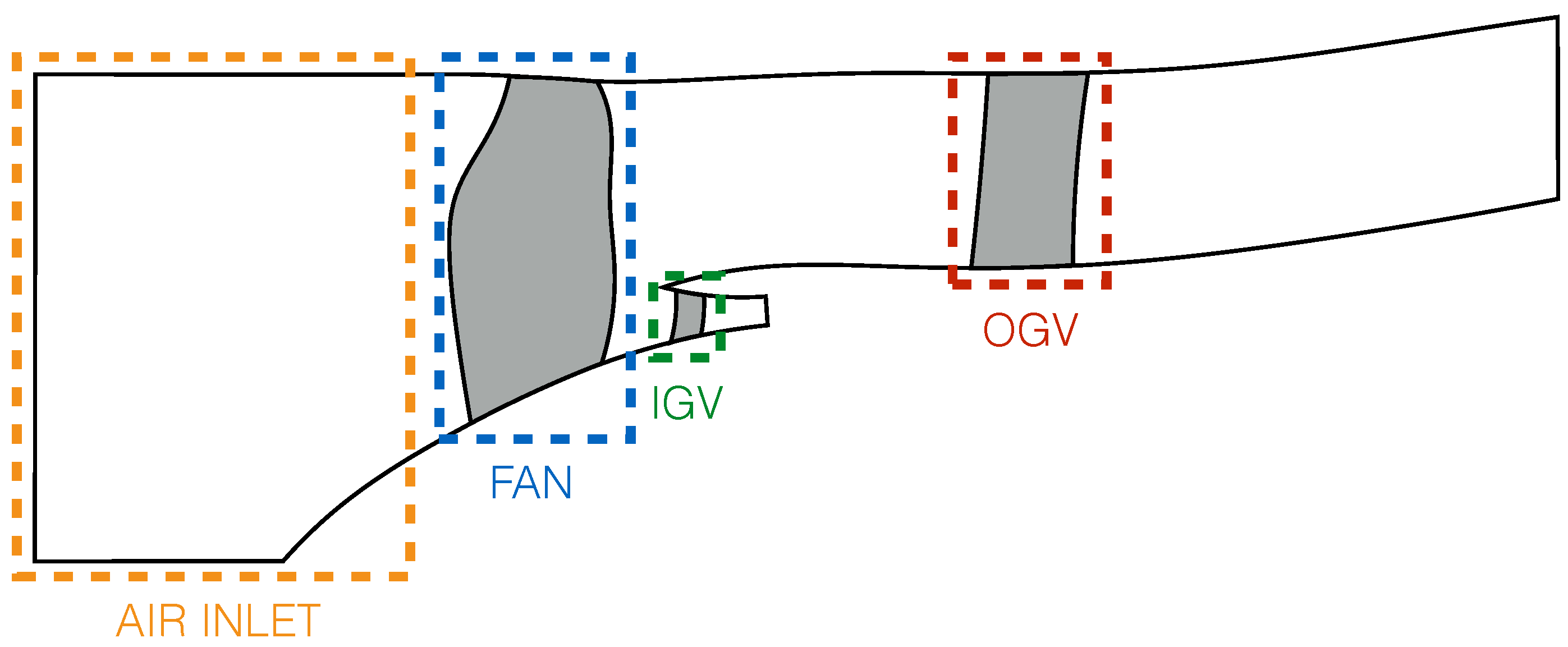
The turbo engine studied here is a typical turbofan, represented in its meridional view in Figure 1. It is composed of an air-inlet duct, a fan and both IGVs and OGVs.
The fan has 18 identical blades. The IGVs are 93 identical vanes, whereas the OGVs are 48 non-identical vanes, including two bifurcations (at 6 and 12 o’clock) and two struts (at 3 and 9 o’clock), as illustrated in Figure 2.
Two different geometries of air-inlet duct are considered here. The first one is perfectly axisymmetric and therefore does not produce any distortion. The other one is asymmetric and has been designed to generate a level of distortion typical of the ones expected for 2020–2025 UHBR engines. Figure 3 shows the duct lines of both air inlets in the 6–12 o’clock plane (vertical plane). The asymmetric air-inlet duct (red dashed lines in (b)) is slightly tilted downwards to offset the deflection of the flow by the wing in cruise conditions.
The operating condition considered here is cutback, one of the three acoustic certification points defined by the International Civil Aviation Organization (ICAO) [31]. It represents a high subsonic regime for the studied turbofan configuration so that shock noise is not considered.

3. Methodology

3.1. CFD Simulation

3.1.1. CFD Solver and Numerical Parameters

The URANS equations are solved with ONERA’s CFD solver elsA [32] based on a cell-centered finite volume approach on a structured multi-block grid. The Wilcox k- ω two-equation model with Zheng’s limiter to avoid the dependence on inlet turbulence is used to determine the turbulent quantities [33,34]. Spatial discretization is achieved with Roe’s scheme (third order accuracy) and temporal discretization with the implicit backward Euler scheme with dual time step (DTS) sub-iteration algorithm (second order accuracy). One blade passage is described by 100 time steps, yielding a total of 1800 time steps per revolution. This was meant to solve frequencies up to the 3BPF.
A uniform flow is specified at the inlet in terms of total pressure, total enthalpy and flow direction. The mass-flow rate is imposed at the exit of the primary flux (downstream of the IGVs), while a pressure condition is used at the exit of the secondary flux (downstream of the OGVs). This pressure condition satisfies the radial equilibrium, and a valve law adjusts the value of pressure at a specified point during the iterations to be as close as possible to a targeted operating point (mass-flow rate and mean pressure). All of the walls are considered as no-slip and adiabatic. Sliding non-conformal interfaces are used between the rotating parts (fan) and the fixed parts (air inlet, IGVs and OGVs).

3.1.2. Mesh

A O4H topology for each blade/vane, a C topology for the nozzle (which separates primary and secondary fluxes) and a butterfly topology in the air inlet to account for the cylindrical domain are used to build the mesh. Stretched sponge zones have been added at the inlet and the outlets of the domain to avoid wave reflections at the boundaries. The same strategy with the same numerical tools and parameters was successfully used by Bonneau et al. [18], and one-dimensional test cases have validated the parameters used for the stretching (i.e., expansion ratio and final cell size). The results presented in this paper are obtained with a mesh of 70 million cells. The discretization is such that there are at least 20 points per wavelength for acoustic waves propagating upstream and 50 points per wavelength for acoustic waves propagating downstream at the BPF. According to one-dimensional test cases, 20 points per wavelength are required to propagate the acoustic waves correctly. The acoustic fluctuations at the BPF should therefore be well propagated. However, predictions up to the 3BPF will be shown in the paper since the propagation is handled by analogy, and the local fine grid resolution around the blades allows resolving the noise sources up to the 3BPF.

3.1.3. Convergence

Twelve rotations have been simulated with both the axisymmetric and the asymmetric air inlets. Only the convergence of the axisymmetric case is shown here for conciseness, but similar levels have been achieved for the asymmetric case. The module of the integrated pressure force F on a blade or on a vane is computed as follows:
F = S p n d S
with p being the static pressure on the surface S of the blade/vane and n being the normal to the wall. The evolution of this force integrated over one fan-blade surface and one (classical) OGV surface during the last two rotations is represented in Figure 4. The sliding average, computed by averaging the signal at each time step over the last period, is also shown. The loadings are normalized by their converged mean values.
On the one hand, the time evolution of the fan force is properly periodic with two lobes: one major lobe with an amplitude of 8% of the mean value caused by the fan-blade passage in front of the upper bifurcation (the big one, at 12 o’clock) and one less important one with a smaller amplitude of 2% of the mean value caused by the lower bifurcation (the small one, at 6 o’clock). The mean value of the fan loading is well converged since no variation during the last two rotations can be noticed. On the other hand, the time evolution of the OGV loading shows a pattern related to the number of fan blades. The 18 lobes observed per revolution in the force evolution are caused by the impacts of the fan-blade wakes. Their relative amplitude is much lower than the one observed in the fan force because of the distortion (0.6% against 8% of the mean value). The OGV mean force is as well converged as the fan-blade force.
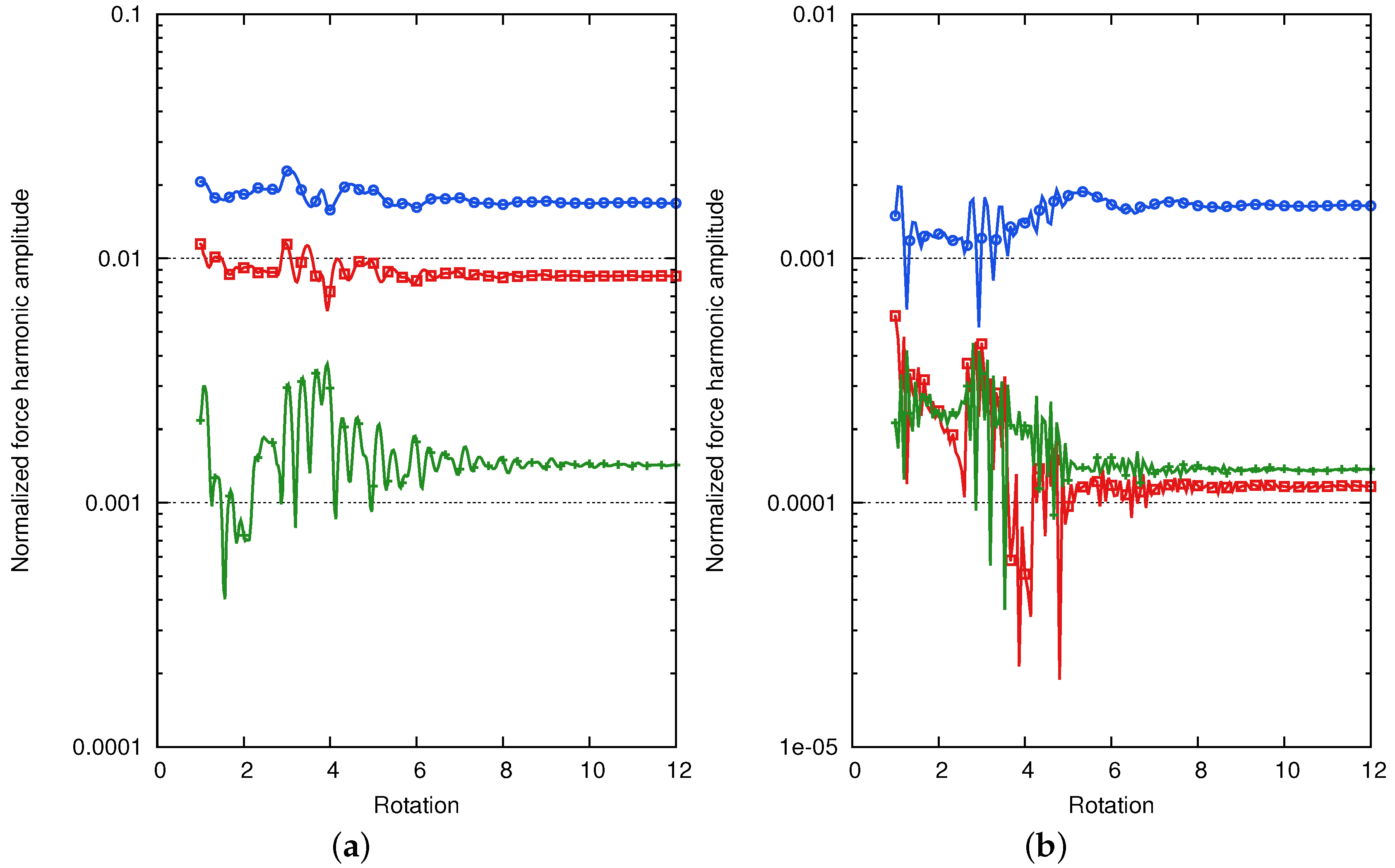
To ensure the acoustic convergence of the simulations, the fan-blade and OGV forces at the frequencies of interest must be converged. Indeed, these loading harmonics are representative of the acoustic sources. Their evolution is shown in Figure 5. The RF and its harmonics are represented for the fan (a) to highlight the interaction with the distortion. For the OGV (b), the BPF and its harmonics, illustrating the interaction with the fan-blade wakes, are chosen. The results have been normalized by the converged values of the corresponding mean force. Both the harmonics of the fan-blade force and the ones of the OGV force reach a plateau after 10 rotations, which ensures the acoustic convergence. The difference between the levels of fan harmonics and OGV harmonics reflects the fact that the oscillations on fan blades are relatively larger than the ones on OGVs. Even if not shown here for the sake of brevity, IGV mean forces and harmonics are also well converged. The convergence of local pressure fluctuations on probes located on the fan blades or on the OGVs and IGVs has also been checked.

3.1.4. Operating Point

During the first fan rotations in the simulations, the secondary-stream outlet pressure has been adjusted in order to be as close as possible to the experimental operating line. This procedure has led to different outlet pressure between the axisymmetric and asymmetric cases, but the priority has been to have a similar operating point.
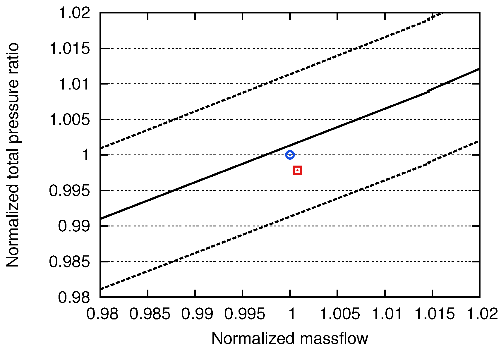
The operating point of each simulation is plotted in the mass-flow rate–total pressure ratio diagram in Figure 6. The performances have been normalized by the axisymmetric case values. Both simulations operate in the ± 1 % error region and then are representative of a normal operating point. Moreover, the difference of performance between the two configurations is very small: 0.08% for the mass-flow rate and 0.2% for the total pressure ratio.

3.2. Acoustic Prediction

3.2.1. Goldstein’s Analogy

Acoustic analogies provide an evaluation of the noise radiated by known sources. The extension of Goldstein’s analogy to the propagation in an infinite annular duct with an axial uniform flow is chosen here. Moreover, assuming that the dipolar sources are the principal contributors of fan tonal noise [35], the in-duct radiated power P ± ( ω ) at pulsation ω is given by:
P ± ( ω ) = k 0 β 0 4 2 ρ 0 c 0 m = + μ = 0 k m μ 2 0 + | S m μ ± ( ω ) | 2 Γ m μ k m μ ( k 0 ± M 0 k m μ ) 2
The upper sign (here +) stands for the upstream radiation, while the lower sign (here −) for the downstream one. ρ 0 is the density, c 0 the speed of sound, M 0 the axial Mach number and k 0 = ω / c 0 the acoustic wavenumber of the reference uniform flow. β 0 is obtained from the Mach number:
β 0 = 1 M 0 2 .
The double sum over m and μ corresponds to the decomposition of the acoustic field into modes of azimuthal order m and radial order μ . Γ m μ is the norm of the modal functions:
Γ m μ = 0 2 π R h R t ψ m μ ( r , θ ) 2 r d r d θ
where R h is the hub radius, R t the tip radius and ψ m μ ( r , θ ) the modal function. ψ m μ ( r , θ ) can be written as follows:
ψ m μ ( r , θ ) = A m μ J m ( κ m μ r ) + B m μ Y m ( κ m μ r ) e i m θ
with J m and Y m the Bessel functions of order m of the first and second kinds, respectively. A m μ and B m μ are duct coefficients, and κ m μ stands for the duct eigenvalues. k m μ is a wavenumber given by the dispersion relationship:
k m μ 2 = k 0 2 β 0 2 κ m μ 2
Its positiveness discriminates the cut-on modes from the cut-off ones. If k m μ 2 < 0 , k m μ is purely imaginary, and the mode (m, μ ) is evanescent and then does not contribute to the far-field radiated power significantly.
Finally, the term S m μ ± ( ω ) includes the acoustic sources and is given in its general form by:
S m μ ± ( ω ) = i 2 π + S ( τ ) y i ψ m μ ( r y , θ y ) e i γ m μ ± y f i ( y , τ ) e i ω τ d S ( y ) d τ
where f i ( y , τ ) represents the loading along the i-direction applied at the time τ on every point y of the source surface S ( τ ) . γ m μ ± is the axial wavenumber written as:
γ m μ ± = M 0 k 0 β 0 2 ± k m μ β 0 2
The term S m μ ± ( ω ) can be simplified for the noise mechanisms considered here. The WSI sources are localized on the stator vanes and are fixed, while the DRI sources are localized on the fan blades and are then rotating at the engine rotational speed Ω . The following expressions for the two mechanisms are then obtained:
  • WSI mechanism:
    S m μ ± ( ω = n B Ω ) = i S y i ψ m μ ( r y , θ y ) e i γ m μ ± y f i ( y , ω = n B Ω ) d S ( y )
  • DRI mechanism:
    S m μ ± ( ω = n B Ω ) = i S y i ψ m μ ( r y , θ y ˜ ) e i γ m μ ± y f i ( y ˜ , ω ˜ = ( n B m ) Ω ) d S ( y ˜ )
    where f i ( y , ω ) stands for the Fourier transform of the blade or vane loading. The main difference between these two mechanisms appears in the source frequencies involved in the radiation at a particular frequency. On the one hand, the sound emitted by the WSI mechanism at nBPF is only caused by the fluctuations of the loadings on stator vanes at the same frequency ( ω = n B Ω ). On the other hand, the sound emitted by the DRI mechanism at nBPF comes from the fluctuations of the loadings on rotor blades at all frequencies ( ω = ( n B m ) Ω with m going from to + ), because of the rotational movement of the sources.

3.2.2. Application

Goldstein’s analogy is used here to estimate the acoustic power from the WSI mechanism for sources located on the OGVs and from the DRI one for sources located on the fan blades. The idea is to evaluate the sound powers radiated by the fan and OGV sources separately and to study their evolution when the air-inlet distortion is added. This is done by performing, for both the axisymmetric and asymmetric configurations, the integration of Equation (7) over the fan-blade surfaces and over the OGV surfaces independently. Therefore, the loading f i ( y , τ ) applied over these surfaces must be stored during the last fan revolution to compute its Fourier transform.
The main advantage of using Goldstein’s analogy is that the propagation is handled analytically. Therefore, the mesh does not need to be able to propagate the acoustic waves correctly at the desired frequencies. It should be fine enough to predict the acoustic sources well, i.e., the unsteady loadings on the fan blades and on the OGVs. These unsteady loadings are caused by the interaction of the vanes with the wakes or the interaction of the blades with the distortion profile. As soon as these excitations are well resolved, Goldstein’s analogy can be used to propagate the related sources.
However, Goldstein’s analogy is a simplified theory. It is only valid for infinite annular ducts (constant hub and tip radius) with a uniform and axial flow, which is not perfectly representative of the studied configuration, particularly in the inter-stage. Moreover, possible reflections within the stage are also neglected. Nevertheless, it will be used here because it provides a fast way to compare the relative weight of each source. A fictitious annular duct with a uniform flow is then defined for the two mechanisms, by choosing a hub radius, a tip radius and mean flow values. Figure 7 illustrates the possible choices for the evaluation of the fan and OGV sources.
Mean flow values are obtained by averaging the different needed values (denoted by the subscript 0 in Equation (2)) in a plane located upstream of the fan for the fan-source upstream propagation and in a plane located downstream of the fan for the fan-source downstream propagation. The same procedure is applied for the OGV sources. The positions of the averaged planes are given by the vertical dotted lines.
The most natural way to define a duct is to use the minimum and maximum radii of the fan blade for the fan sources and of the stator vane for the OGV sources. This makes sense for the OGV sources since the duct is almost annular in the stator region. However, in the fan region, the hub radius varies along the spinner so that the definition of an annular duct is not straightforward. This is why two ducts are presently used: one cylindrical for the upstream propagation and the other defined with OGV minimum and maximum radii for the downstream propagation. These ducts are represented by the horizontal dashed lines.

4. Results

4.1. Aerodynamic Analysis

4.1.1. Basic Flow Patterns

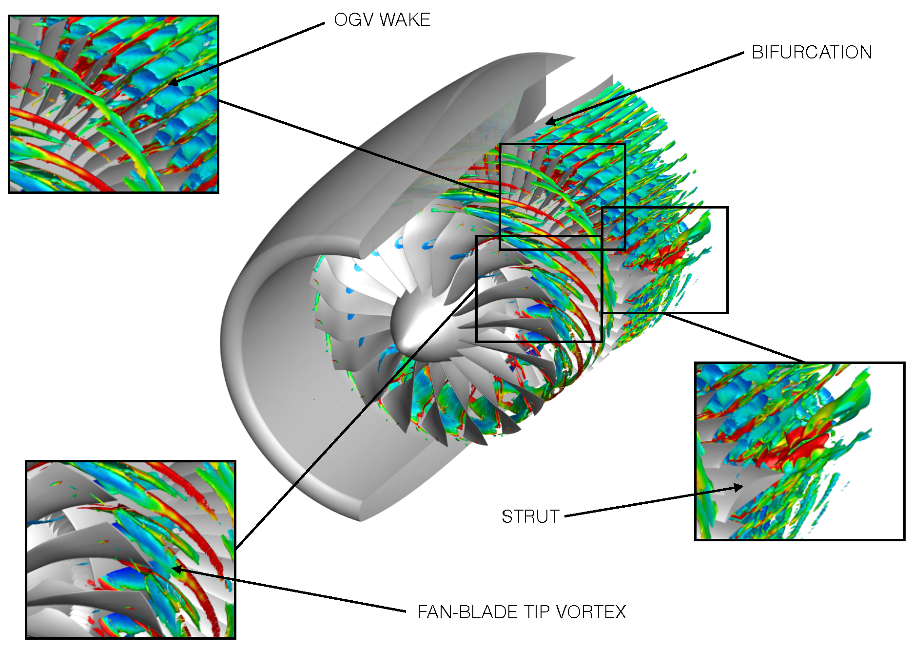
A basic flow analysis is first provided to show the main flow patterns. An iso-surface of the Q-criterion colored by the vorticity modulus is represented in Figure 8 for the axisymmetric air-inlet case. The fan-blade wakes are propagating far in the bypass duct. The fan-blade tip vortices are impacting the OGVs. The flow inhomogeneity can be noticed around the pylon (or bifurcation) and the struts, as well as the flow separating from the visible strut. Note that the nacelle is represented here for a better understanding of the computational domain, but only the interior part of the duct is actually simulated.
Instantaneous maps of entropy and Mach number at mid-span are shown in Figure 9 to provide the overall flow topology far from the hub and the shroud. The entropy field highlights both the fan-blade wakes impacting the OGVs and the OGV wakes, both making a checker-board pattern downstream. The strut wake crosses the wake of its neighbor vane, which stresses the important inhomogeneity of the OGV row. The latter effect is also clearly seen in the absolute Mach number field. The pylon slows down the flow and introduces a significant distortion that is quantified below in Section 4.1.2.

4.1.2. Quantification of the Distortion

The focus is put here on the distortion since it usually causes the neglected sources on fan blades. As it is stationary, it will periodically interact with the fan rotating blades and will then be responsible for the unsteady blade loadings. Contour maps of static pressure are thus given in Figure 10 for the two different air-inlet geometries at mid-span (50% of channel height) and close to the tip (95% of channel height). The distortion caused by the potential effects of the structural pylon is clearly seen in all maps and is quickly damped when approaching the fan. The asymmetric air inlet introduces an additional distortion, which is maximum around the fan and in the tip region. Downstream of the OGVs, this additional distortion has a mitigated effect since the pylon dictates the flow topology.
The intensity of the distortion is quantified by calculating the circumferential distortion coefficient (CDC) at different axial positions x for a constant channel height h / H defined as:
C D C ( x , h / H ) = Max θ [ M ( x , h / H , θ ) ] Min θ [ M ( x , h / H , θ ) ] Mean θ [ M ( x , h / H , θ ) ]
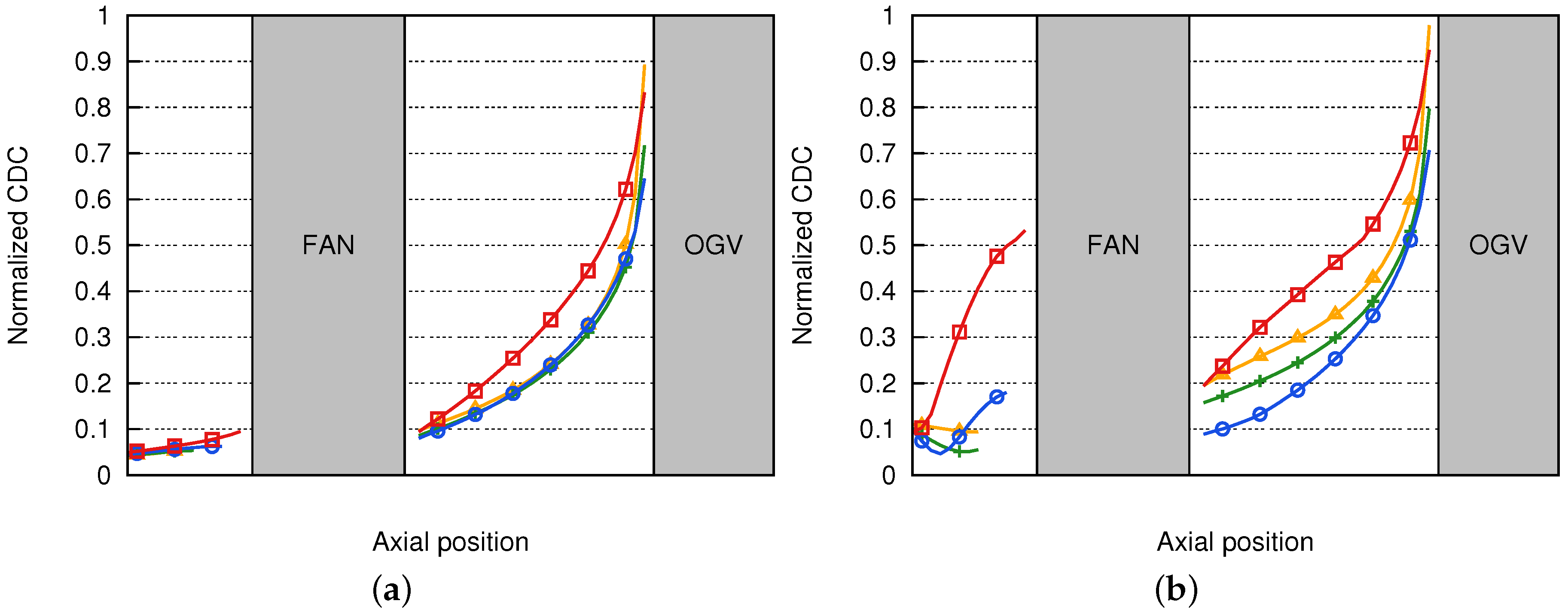
where Max θ [ M ( x , h / H , θ ) ] , Min θ [ M ( x , h / H , θ ) ] and Mean θ [ M ( x , h / H , θ ) ] are the azimuthal maximum, minimum and mean values of the Mach number at position (x, h / H ) respectively. This coefficient, normalized by its maximum value, is plotted for both air inlets along the machine rotational axis at 25%, 50%, 75% and 95% of channel height in Figure 11. The previous observations are confirmed here, with an important distortion coming from the structural pylon and further emphasized in the tip region (95% of channel height). The asymmetry of the air inlet has a huge influence on the distortion in the fan-blade tip region, where the CDC is almost six-times higher than in the axisymmetric case. It also introduces a significant additional distortion upstream of the OGVs. This is evidence that the air-inlet geometry has an effect on the flow downstream of the fan.
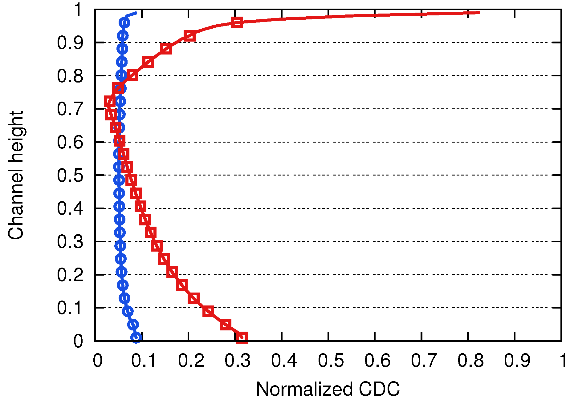
To have a better idea of the radial evolution of the distortion, the CDC has been computed in a plane right upstream of the fan (where it is expected to be dominant from Figure 11) at many different channel heights. Results are shown in Figure 12. The distortion that comes from the potential disturbance of the pylon is present in the axisymmetric geometry and is almost constant over the span. However, the air-inlet distortion presents a strong radial variation, with bigger levels close to the hub and shroud. The CDC is three-times higher than in the axisymmetric case in the hub region, but the maximum effect is located close to the tip with a level more than eight-times higher.

4.1.3. Impact of Air Inlet Distortion on the Harmonics of Fan-Blade Forces

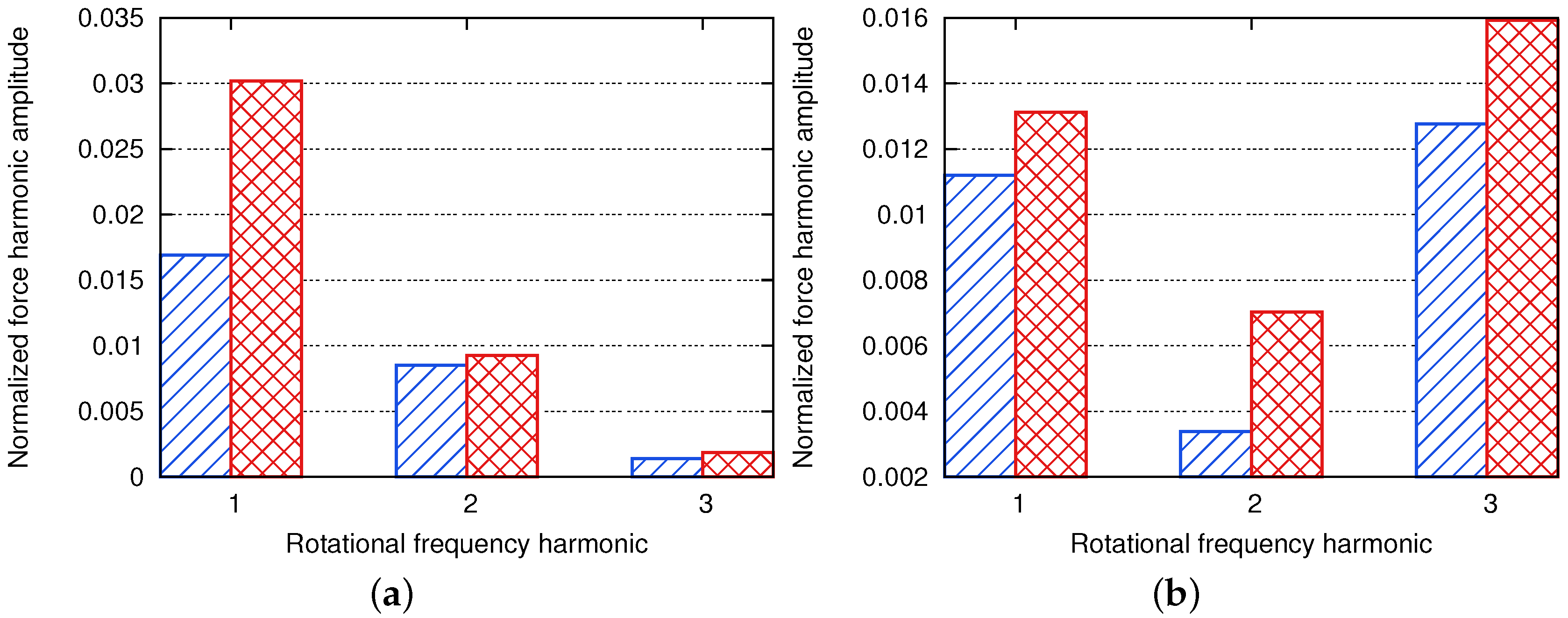
The significant augmentation of distortion, as it interacts with the rotating fan, will be responsible for an increase of the unsteady loadings on the fan blades. This will be quantified here by calculating the first harmonics of the integrated fan-blade loadings for both air-inlet geometries. The loading at the RF and its harmonics are computed for each blade, and both the mean value and the standard deviation are presented in Figure 13. For each harmonic, mean value results have been normalized by the mean value of the time-averaged fan-blade force obtained in the axisymmetric air-inlet case. Standard deviations have been normalized by the mean value of the fan-blade loading at the corresponding harmonic in the axisymmetric air-inlet case.
As expected from the previous results, the levels at the RF and its harmonics are much higher in the asymmetric case. The maximum difference is seen at the RF that represents the main pattern of the air-inlet distortion, with a level almost twice higher. This result should have an important consequence on the stage acoustics as Goldstein’s analogy applied to the DRI mechanism described in Section 3.2.1 links the radiated power to the harmonics of the fan-blade loading. The standard deviation is very small for all harmonics (less than 2%) and for both air-inlet geometries since all blades are identical and interact with the same distortion.

4.1.4. Impact of Air Inlet Distortion on Fan-Blade Wakes

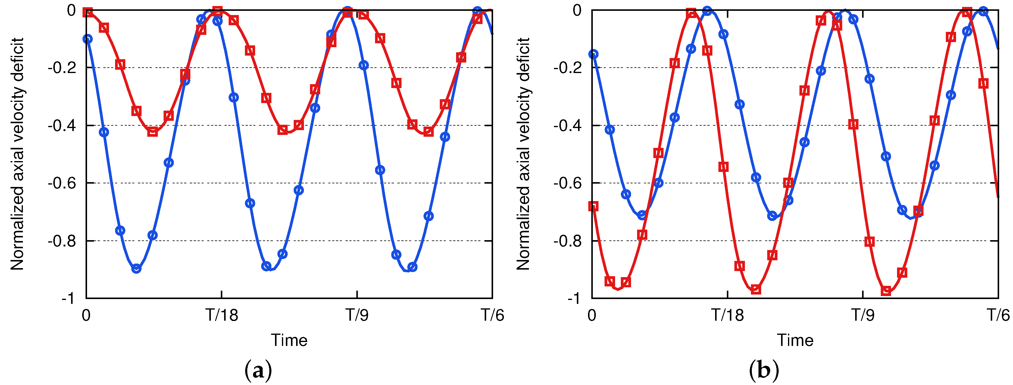
Figure 11 also shows that the air-inlet asymmetry has an influence on the distortion level upstream of the OGVs. The shape of the fan-blade wakes may then be altered by the air-inlet distortion. In such a case, the WSI sources caused by the interaction of these wakes with the OGVs will be modified. In order to check it, the temporal evolution over one sixth of a rotation of the normalized axial velocity deficit extracted at two probe locations is plotted in Figure 14. The probes are located midway between the fan and the OGVs, at 95% of vane height. They correspond to two azimuthal positions θ 1 and θ 2 that are spaced by 2 π / 3 (equivalent to the space between six blades) so that they are supposed to see the passage of fan-blade wakes at the same time.
The effect of distortion on the shape of fan-blade wakes is drastic. Even in the axisymmetric configuration, the potential disturbance of the pylon causes differences of about 25% in the velocity deficit between the two azimuthal positions. The additional distortion coming from the asymmetric air inlet is responsible for a deviation of the peaks and strongly modifies the velocity deficits (ratio greater than two at θ = θ 1 for instance).

4.1.5. Impact of Air Inlet Distortion on the Harmonics of OGV Forces

The modification of the fan-blade wakes is responsible for the modification of the OGV loadings at the BPF and its harmonics. This effect is quantified using the same procedure as the one used for fan forces. The loadings at the BPF and its harmonics are computed for each vane (including struts and pylon), and both the mean value and the standard deviation are given in Figure 15. The only difference with fan-blade forces is that the frequency of interest is the BPF (impact of wakes) and no longer the RF. The normalization of the results has been done in the same way.
The asymmetry of the air inlet is responsible for a force modulus more than twice higher at the BPF. As was mentioned for the fan-blade force harmonics already, this result is determinant for the stage acoustics since Goldstein’s analogy applied to the WSI mechanism described in Section 3.2.1 links the radiated power to the OGV loading harmonics. Contrary to the harmonics of fan-blade forces, the standard deviation of the OGV force harmonics is very high and is drastically increased with the air-inlet distortion. The maximum values are reached at the BPF with a level of approximately 70% in the axisymmetric case and 140% in the asymmetric one. This means that the amplitude of the integrated force at the BPF and its harmonics greatly varies from one vane to another. This can be related to the observations in Figure 14, which highlights the variation of the wake shapes with the azimuthal position. Such a behavior is caused by the distortion, and this is why it is increased in the asymmetric configuration.

4.2. Acoustic Analysis

4.2.1. Source Breakdown

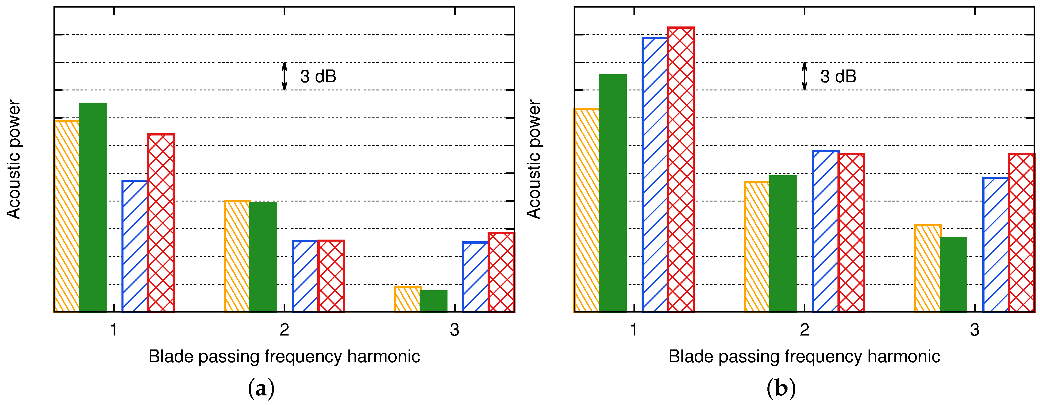
In Section 4.1.3 and Section 4.1.5, the distortion has been shown to have an important influence on the harmonics of both fan-blade and OGV loadings. The idea here is to estimate the acoustic impact of this distortion with Goldstein’s analogy following the methodology described in Section 3.2.1. The radiated noise by the fan and OGV sources is evaluated separately with Equation (2). Figure 16 shows the upstream (a) and the downstream (b) noise radiated at the BPF and its first two harmonics by the fan and the OGV sources in both the axisymmetric and the asymmetric cases. The same scale has been used for both plots.
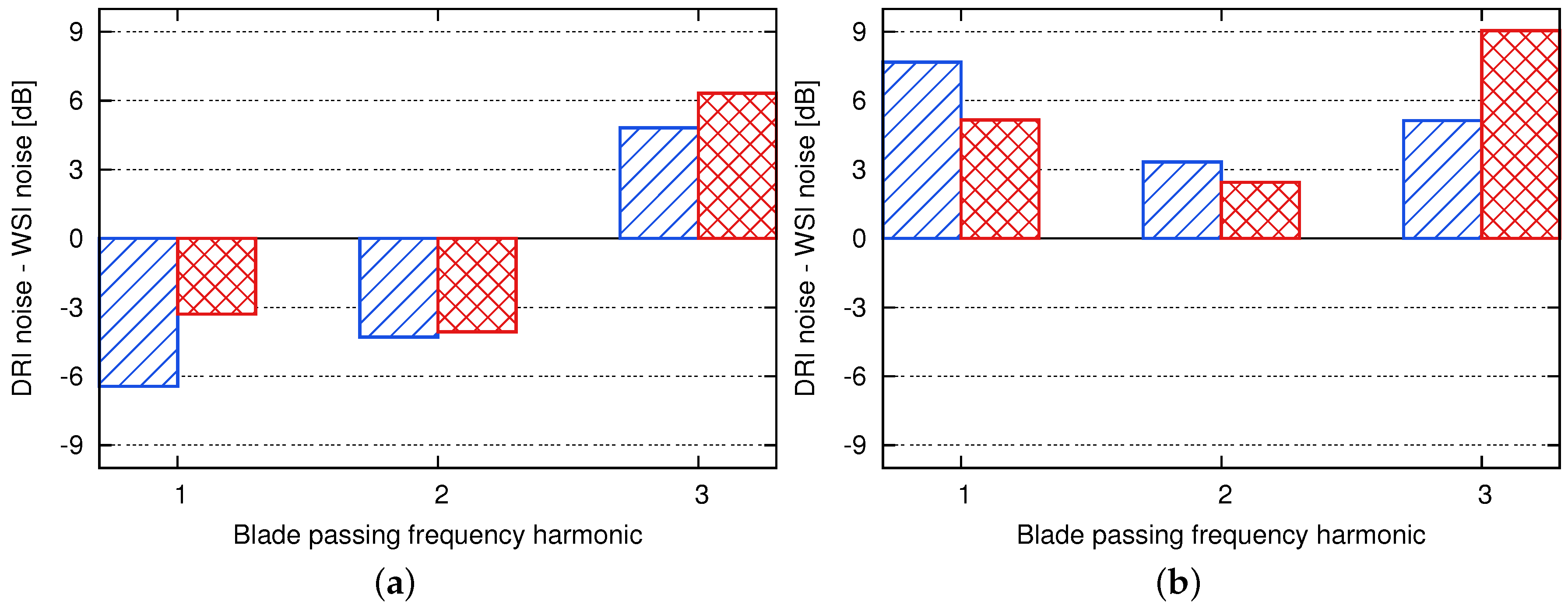
The focus is first put on the relative contribution of the sources caused by the WSI mechanism (or OGV sources) and the sources caused by the DRI mechanism (or fan sources). The difference between the noise of these two mechanisms for each harmonic and for both the axisymmetric and the asymmetric cases is presented in Figure 17. A positive value means that the DRI mechanism dominates the WSI one and vice versa.
In this particular case, the WSI mechanism is dominant in the upstream radiation except at 3BPF. At 1BPF and 2BPF, the WSI noise is 3–6 dB higher than the DRI one. The air-inlet distortion reduces this difference. For the downstream propagation, the DRI mechanism is dominant (+3–+9 dB), even for the axisymmetric air inlet. The air-inlet distortion again reduces this difference for the BPF and its first harmonic.

4.2.2. Acoustic Penalty Induced by the Air Inlet Distortion

The impact of the air-inlet distortion on the radiated noise is now quantified by the acoustic penalty on each noise mechanism, defined as the difference in decibels of the noise levels between the asymmetric and the axisymmetric cases. Figure 18 provides the levels for the upstream (a) and downstream (b) noise radiation. A positive value means that the noise of the considered mechanism is increased by the air-inlet distortion.
The main effects are seen at 1BPF. For the upstream radiation, the air-inlet distortion has a bigger influence on the DRI mechanism (about +5 dB) than on the WSI one (about +2 dB). Yet, the latter is still the dominant mechanism as shown in Figure 17. For the downstream radiation, the results are reversed. The air-inlet distortion has a main influence on the WSI mechanism (almost +4 dB) and hardly one on the DRI mechanism (around +1 dB), but the latter still dominates.
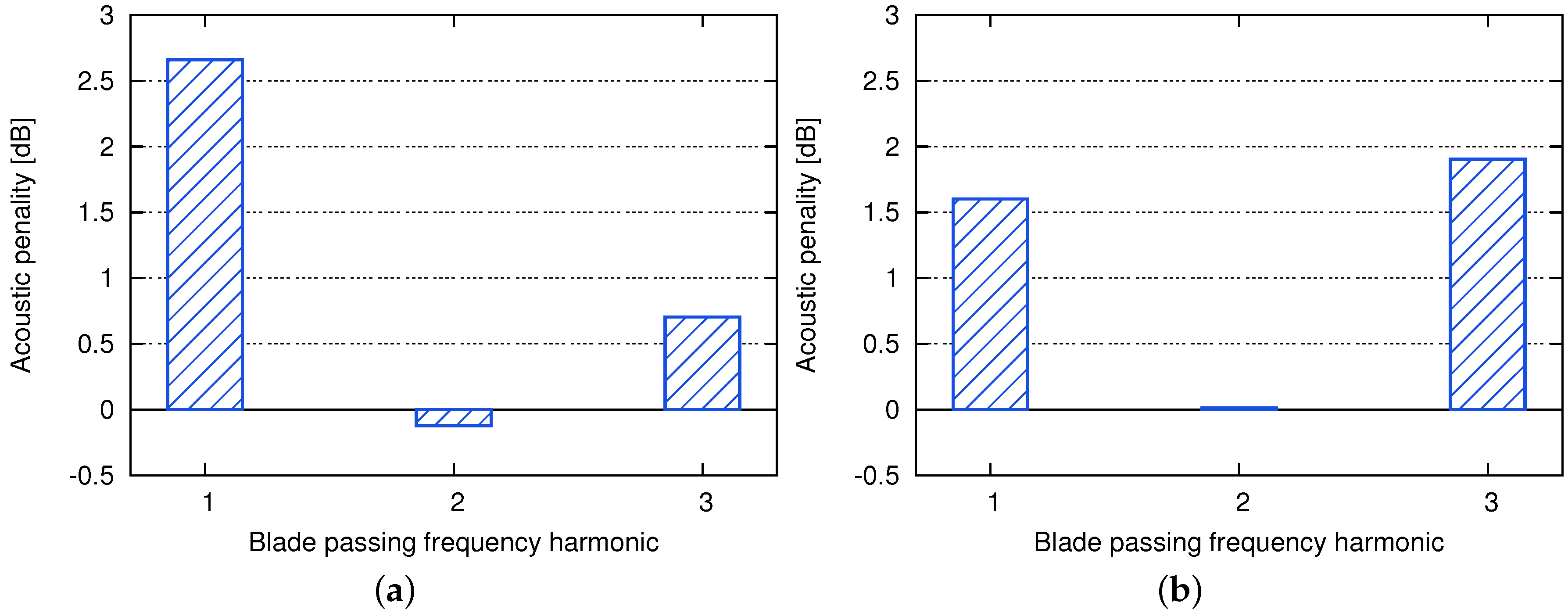
The total acoustic penalty caused by the air-inlet distortion is now estimated by subtracting the total noise (WSI noise + DRI noise) radiated in the axisymmetric case from the one radiated in the asymmetric case. Results are shown in Figure 19 for the upstream (a) and downstream noise radiation (b).
The influence of the air-inlet distortion is highlighted in both upstream and downstream radiated powers. The main effect appears at 1BPF for the upstream radiation (about +2.5 dB) and at 1BPF and 3BPF for the downstream one (about +1.5 dB and +2 dB, respectively). These results tend to stress a significant impact of the air-inlet distortion on the fan tonal noise for the studied configuration (cutback operating point). However, they have been obtained using Goldstein’s analogy, which makes assumptions on the flow and the geometry of the configuration. The robustness of the method is thus studied by testing some assumptions and varying some parameters in Section 4.2.4. Before this parametric study, a modal analysis is achieved below, in Section 4.2.3, to provide a deeper understanding of the above results.

4.2.3. Modal Analysis

The radiated power of each azimuthal mode m is extracted from Equation (2):
P m ± ( ω ) = k 0 β 0 4 2 ρ 0 c 0 μ = 0 k m μ 2 0 + | S m μ ± ( ω ) | 2 Γ m μ k m μ ( k 0 ± M 0 k m μ ) 2
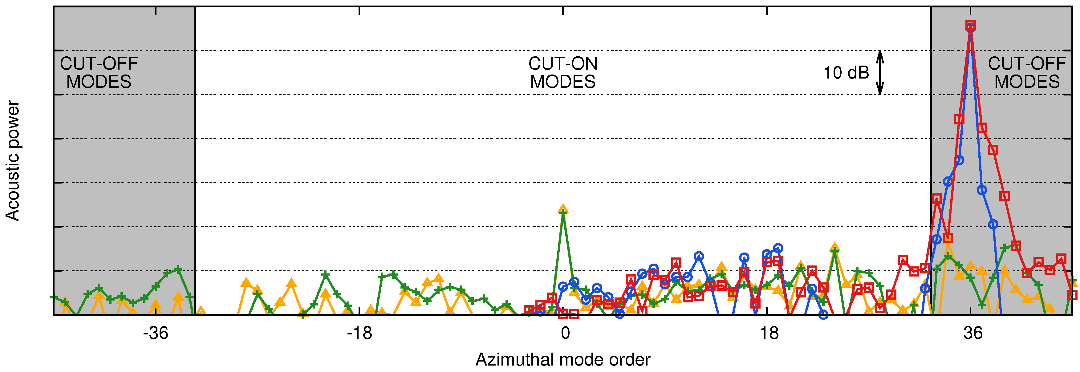
As a representative example, the results obtained at 2BPF radiated upstream are plotted in Figure 20 for both the axisymmetric and the asymmetric geometries. To make the following explanations clearer, the cut-off modes (located in the grey regions) are represented without accounting for their attenuation. In practice, their amplitude exponentially decreases while getting farther from the source so that they should not contribute to the radiated power.
The behavior of the modes radiated by the fan sources and the OGV sources is quite different. The modes caused by the WSI mechanism are all linked to the fluctuations on the OGVs at 2BPF as shown by Equation (9). No particular evolution of these mode amplitudes can be drawn, and the effect of the air-inlet distortion on the WSI mechanism is spread over all modes. If the OGV row was homogeneous, and the flow was free of distortion, the classical Tyler and Sofrin modes ( m = n B k V with B the number of fan blades, V the number of OGVs, n the multiple of the BPF considered and k an integer) would have emerged [25]. For the represented BPF harmonic ( n = 2 ), it would have corresponded to the modes 36 and 12 . In the studied configuration, not only the OGV row is completely heterogeneous (every vane geometry is different), but also the flow is distorted. The irregularity of the wakes observed in Figure 14 makes each vane response different from each other, and this is emphasized by the differences in the geometries. The classical Tyler and Sofrin theory that predicts the modes caused by the interaction of the wakes of a homogeneous rotor with the vanes of a homogeneous stator cannot be applied. It should be adapted by taking V equal to one to model the heterogeneous stator. With this arrangement, the theory only says that any integer mode m can be excited ( m = n B k ), and this is what is observed here. This result has also been highlighted by Bonneau et al. [18].
On the contrary, the modes due to the DRI mechanism present a peculiar evolution. As shown by Equation (10), the mode m is linked to the fluctuations on the fan blades at the ( n B m ) -th multiple of the RF. Since the most important fluctuations of fan-blade loading correspond to the RF and its first harmonics (interaction with the distortion), the most important modes will be close to the rotor-locked mode m = n B = 36 . The modes m = 35 and m = 37 logically emerge here. This explains why the air-inlet distortion has its main influence on the DRI mechanism on the modes around the rotor-locked mode.
Therefore, the position of the cut-off criterion seems to be determinant on the contribution of fan sources and on the acoustic penalty due to air-inlet distortion. Indeed, if the position of the cut-off criterion is slightly shifted towards the high azimuthal orders, the most important modes due to the distortion will become cut-on and will dominate the total noise radiated. In such a case, the air-inlet distortion will have a big influence since the dominant modes are even more dominant in the asymmetric case. The cut-off boundaries have been determined here considering a uniform duct with a uniform and axial flow. Clearly, they might be shifted when considering the real geometry and flow conditions (swirling flow typically). They are determinant on the noise predictions, and the uncertainty on their position is a limitation of the current approach.

4.2.4. Robustness of the Method

Figure 20 highlights the importance of the position of the cut-off criterion on the results presented above. However, this cut-off criterion, given in Section 3.2.1, depends on both the mean flow characteristics and the duct radii. Since the studied configuration is not annular and the flow is not uniform, an average procedure has been used to define the mean flow values, and some simplifications have led to the choice of the hub and tip duct radii (detailed in Section 3.2.2). The sensitivity of the total acoustic penalty induced by the air-inlet distortion is evaluated here by choosing different mean flow values and by changing the duct radii.
Four sets of parameters are studied.
  • First set: The same ducts as the ones defined in Figure 7 are considered. Axisymmetric flow parameters are used for both the axisymmetric and asymmetric power estimates. This has the advantage of using the same cut-off criterion for both cases. This set corresponds to the results presented above.
  • Second set: The same ducts as the ones defined in Figure 7 are considered. However, the axisymmetric flow parameters are used for the axisymmetric power estimate, and the asymmetric flow parameters are used for the asymmetric one. A maximum difference of 5% is obtained on the Mach number upstream of the fan.
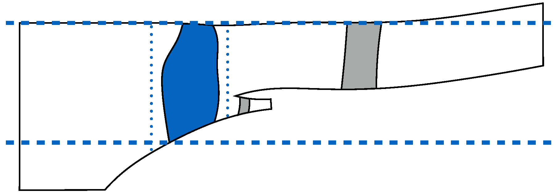
  • Third set: For the OGV sources, the same duct as the one defined in Figure 7 is used. However, the duct used for the fan sources is modified. It now corresponds to the minimum and maximum radii of the fan blade. This new duct definition is represented by the blue horizontal lines in Figure 21. Similarly to the first set, axisymmetric flow parameters are used for both the axisymmetric and asymmetric power estimates. This again has the advantage of using the same cut-off criterion for both cases.
  • Fourth set: The same ducts as the ones defined for the third set are used. However, similarly to the second set, the axisymmetric flow parameters are used for the axisymmetric power estimate, and the asymmetric flow parameters are used for the asymmetric one. A maximum difference of 5% is obtained on the Mach number upstream of the fan.
The total acoustic penalty caused by the air-inlet distortion is evaluated for each set of parameters, and the results are presented in Figure 22 for the upstream (a) and the downstream noise (b).
The results show an effect of the mean flow parameters (Mach number M 0 , density ρ 0 and speed of sound c 0 ) on the upstream radiation, especially at 1BPF with a difference of about 1 dB. This is caused by the modification of the flow upstream of the fan by the inlet distortion. However, the choice of the duct for the upstream radiation of fan sources (cylindrical or annular) has no influence on the acoustic penalty as the DRI mechanism is not dominant.
For the downstream radiation, the influence of the mean flow parameters is less noticeable as the mean flow values downstream of the fan and OGVs are hardly modified by the inlet distortion. Contrary to the upstream radiation, the definition of the duct for the downstream radiation of fan sources (annular with fan-blade or OGV extreme radii) has a major effect since the DRI mechanism is dominant. This is particularly true at 2BPF and 3BPF with a difference of almost 2 dB. The change of the duct definition can make some cut-off modes cut-on and vice versa. This in turn can change the radiated power greatly since the modes near the cut-off/cut-on transition are close to the rotor-locked mode and are then the most powerful ones.
These ambiguities in the definition of the annular duct and the mean flow could be alleviated by accounting for a slowly-varying duct formulation [13,14]. Moreover, the presence of a swirling flow in the fan-OGV inter-stage will also modify the radiated powers. An analogy that accounts for this effect has been derived recently [15,16], and the first studies stressed its importance [36]. Those advanced prediction methods should improve the acoustic predictions that are made in the present study.

5. Discussion

The influence of distortion on fan tonal noise at the cutback condition has been successfully investigated in a realistic UHBR configuration. Usually, such a tonal noise is assumed to be dominated by the interaction of fan-blade wakes with the OGVs. However, this may not be the case anymore in future UHBR engines, in which the pylon is integrated in the OGVs and where the air-inlet duct is shortened as much as possible. These two evolutions are responsible for a distortion that will interact with the fan and will be responsible for additional acoustic sources on its blades.
In order to evaluate the acoustic impact of this distortion, two simulations of a complete full-annulus fan module have been achieved for the first time. The model includes an air inlet (axisymmetric for one case and asymmetric for the other), a fan, all IGVs and heterogeneous OGVs including struts and pylon. The asymmetric air inlet has been specifically designed to provide a level of distortion close to the ones expected in future UHBR engines. The extension of Goldstein’s analogy to infinite annular ducts with uniform axial flow has then been used to evaluate and compare the noise radiated by the fan sources and the OGV sources for each configuration.
The distortion caused by the potential effect of the pylon has been shown to be maximum in the OGVs region and to quickly decrease while propagating towards the fan. The added distortion of the asymmetric air inlet has a main effect in the fan-tip region, where the distortion index has been multiplied by six. This in turn is responsible for an important increase of the first harmonics of the fan-blade loadings and then for an important rise of acoustic sources localized on the fan blades. Moreover, the air-inlet distortion is also seen to modify the shape of the wakes around the fan tip and to yield a strong variation of the OGV forces at the BPF and its harmonics. The acoustic sources localized on the OGVs are thus also modified by the distortion.
The acoustic predictions based on Goldstein’s analogy have shown that the fan sources should be considered for the evaluation of fan tonal noise. Indeed, they dominate the OGV sources in the downstream radiation and are important in the upstream radiation at 2BPF and 3BPF. The distortion caused by the asymmetry of the air inlet is responsible for an increase of the noise radiated by both the fan and OGV sources, yielding a global penalty of up to three decibels.
Important assumptions have been made to provide these first acoustic predictions, namely propagation in an infinite annular duct with a mean axial flow. They could be improved by accounting for slowly varying ducts and swirling flows in the fan-OGV inter-stage. In addition, UHBR engines will be characterized by short inlets for which the infinite duct assumption might be violated. Consequently, simulations based on the linearized euler equations (LEE), which are much less expensive than CFD simulations, might be used to propagate the sources correctly in the upstream direction. Direct acoustic predictions, in which the power is evaluated directly from the fluctuations given by the simulation, should also be achieved in order to remove all assumptions. Moreover, only the two main noise mechanisms at subsonic tip conditions, i.e., the interaction of fan-blade wakes with OGVs and the interaction of distortion with fan blades, have been considered here and compared. Some more complex mechanisms, such as the scattered OGV sound field by the fan and vice versa and the wave propagation effects within the blade passages, should also be studied. Those phenomena were likely underestimated (at least at 2BPF and 3BPF) in the actual simulations since they require meshes and schemes able to propagate the acoustic waves correctly at the targeted frequencies. Finally, the analysis of a transonic regime should also be addressed to evaluate the possible impact of distortion on the shock-noise mechanism.

Acknowledgments

The authors are thankful to Safran Aircraft Engines for having funded this study, to ONERA for licensing CERFACS to use the code elsA and to Marc Montagnac from CERFACS for his help in the preparation of the numerical simulations. This work was performed using HPC resources from GENCI—[CCRT/CINES/IDRIS] (Grant 2016-[x20162a6074]).

Author Contributions

Stéphane Moreau, Nicolas Gourdain, Jean-François Boussuge and Claude Sensiau conceived and designed the study. Majd Daroukh performed the numerical simulations, and Majd Daroukh, Stéphane Moreau, Nicolas Gourdain, Jean-François Boussuge and Claude Sensiau analyzed and interpreted the data. Majd Daroukh and Stéphane Moreau wrote the paper, and Nicolas Gourdain, Jean-François Boussuge and Claude Sensiau critically revised the manuscript.

Conflicts of Interest

The authors declare no conflict of interest.

Abbreviations

The following abbreviations are used in this manuscript:
BPFBlade Passing Frequency
CAAComputational AeroAcoustics
CDCCircumferential Distortion Coefficient
CFDComputational Fluid Dynamics
DRIDistortion-Rotor Interaction
IGVInlet Guide Vane
OGVOutlet Guide Vane
RFRotational Frequency
UHBRUltra High Bypass Ratio
URANSUnsteady Reynolds-Averaged Navier–Stokes
WSIWakes-Stator Interaction

Nomenclature

The following symbols are used in this manuscript:
Latin Symbols
A m μ First mode amplitude coefficient related to the mode ( m , μ )
BNumber of rotor blades
B m μ Second mode amplitude coefficient related to the mode ( m , μ )
c 0 Speed of sound of the uniform flow
f i Local force on the fan blades or on the OGVs along the i-direction
FIntegrated force on the fan blades or on the OGVs
h / H Channel height ratio
J m Bessel function of the first kind
kAny integer
k 0 Wavenumber of the uniform flow
k m μ Modal coefficient related to the mode ( m , μ )
mAzimuthal order of the mode ( m , μ )
MMach number
M 0 Axial Mach number of the uniform flow
nBPF harmonic number
n Normal vector to the wall
pStatic pressure on the fan blades or on the OGVs
P ± Acoustic power radiated upstream (+ sign) or downstream (− sign)
R h Hub radius
R t Tip radius
SSource surface
S m μ ± Source term related to the mode ( m , μ )
VNumber of stator vanes
x Observer position in the fixed frame with the cylindrical coordinates (r, θ , x)
y Source position in the fixed frame with the cylindrical coordinates ( r y , θ y , y)
y ˜ Source position in the rotating frame with the cylindrical coordinates ( r y , θ y ˜ , y)
Y m Bessel function of the second kind
Greek Symbols
β 0 Compressibility factor of the uniform flow
γ m μ ± Axial wavenumber related to the mode ( m , μ )
Γ m μ Norm of the modal function Ψ m μ related to the mode ( m , μ )
κ m μ Duct eigenvalue related to the mode ( m , μ )
μ Radial order of the mode ( m , μ )
ρ 0 Density of the uniform flow
τ Emission time
Ψ m μ Modal function related to the mode ( m , μ )
ω Pulsation
Ω Engine rotational speed

References

  1. Lighthill, M. On sound generated aerodynamically. I. General theory. Proc. R. Soc. A 1952, 211, 564–587. [Google Scholar] [CrossRef]
  2. Amiet, R.K. Acoustic radiation from an airfoil in a turbulent stream. J. Sound Vib. 1975, 41, 407–420. [Google Scholar] [CrossRef]
  3. Paterson, R.W.; Amiet, R.K. Acoustic Radiation and Surface Pressure Characteristics of an Airfoil Due to Incident Turbulence; Technical Report; National Aeronautics and Space Administration: Washington, DC, USA, 1976.
  4. Ventres, C.S.; Theobald, M.A.; Mark, W.D. Turbofan Noise Generation. Volume 1: Analysis; Technical Report; National Aeronautics and Space Administration Lewis Research Center: Cleveland, OH, USA, 1982.
  5. Glegg, S.A.L. The response of a swept blade row to a three-dimensional gust. J. Sound Vib. 1999, 227, 29–64. [Google Scholar] [CrossRef]
  6. Hanson, B. Theory for Broadband Noise of Rotor and Stator Cascades with Inhomogeneous Inflow Turbulence Including Effects of Lean and Sweep; Technical Report; National Aeronautics and Space Administration: Washington, DC, USA, 2001.
  7. Posson, H.; Roger, M.; Moreau, S. On a uniformly valid analytical rectilinear cascade response function. J. Fluid Mech. 2010, 663, 22–52. [Google Scholar] [CrossRef]
  8. Posson, H.; Moreau, S.; Roger, M. On the use of a uniformly valid analytical cascade response function for fan broadband noise predictions. J. Sound Vib. 2010, 329, 3721–3743. [Google Scholar] [CrossRef]
  9. De Laborderie, J.; Moreau, S. Evaluation of a Cascade-Based Acoustic Model for Fan Tonal Noise Prediction. AIAA J. 2014, 52, 2877–2890. [Google Scholar] [CrossRef]
  10. De Laborderie, J.; Blandeau, V.; Node-Langlois, T.; Moreau, S. Extension of a Fan Tonal Noise Cascade Model for Camber Effects. AIAA J. 2015, 53, 863–876. [Google Scholar] [CrossRef]
  11. De Laborderie, J.; Moreau, S. Prediction of tonal ducted fan noise. J. Sound Vib. 2016, 372, 105–132. [Google Scholar] [CrossRef]
  12. Goldstein, M. Aeroacoustics; McGraw-Hill Inc.: New York, NY, USA, 1976. [Google Scholar]
  13. Rienstra, S.W. Sound transmission in slowly varying circular and annular lined ducts with flow. J. Fluid Mech. 1999, 380, 279–296. [Google Scholar] [CrossRef]
  14. Ovenden, N.C. A uniformly valid multiple scales solution for cut-on cut-off transition of sound in flow ducts. J. Sound Vib. 2005, 286, 403–416. [Google Scholar] [CrossRef]
  15. Posson, H.; Peake, N. The acoustic analogy in an annular duct with swirling mean flow. J. Fluid Mech. 2013, 726, 439–475. [Google Scholar] [CrossRef]
  16. Matthews, J.; Peake, N. The acoustic Green’s function for swirling flow in a lined duct. J. Sound Vib. 2017, 395, 294–316. [Google Scholar] [CrossRef]
  17. Rumsey, C.L.; Biedron, R.T.; Farassat, F.; Spence, P.L. Ducted-fan engine acoustic predictions using a Navier–Stokes code. J. Sound Vib. 1998, 213, 643–664. [Google Scholar] [CrossRef]
  18. Bonneau, V.; Polacsek, C.; Barrier, R.; Lewy, S.; Roux, J.M.; Gervais, Y. Tonal Noise Prediction of a Turbofan with Heterogeneous Stator and Bifurcations. AIAA J. 2015, 53, 3354–3369. [Google Scholar] [CrossRef]
  19. Kopitz, J.; Bröcker, E.; Polifke, W. Characteristics-based filter for identification of planar acoustic waves in numerical simulation of turbulent compressible flow. In Proceedings of the 12th International Congress on Sound and Vibration, Lisbon, Portugal, 11–14 July 2005. [Google Scholar]
  20. Envia, E.; Wilson, A.; Huff, D. Fan Noise: A Challenge to CAA. Int. J. Comput. Fluid Dyn. 2004, 18, 471–480. [Google Scholar] [CrossRef]
  21. De Laborderie, J. Approches Analytiques et Numériques Pour la Prédiction du Bruit Tonal et Large Bande de Soufflantes de Turboréacteurs. Ph.D. Thesis, Université de Sherbrooke, Sherbrooke, QC, Canada, 2013. [Google Scholar]
  22. Holewa, A.; Weckmüller, C.; Guérin, S. Impact of Bypass Duct Bifurcations on Fan Noise. In Proceedings of the 18th AIAA/CEAS Aeroacoustics Conference, Colorado Springs, CO, USA, 4–6 June 2012. [Google Scholar]
  23. Bonneau, V. Prévision du Bruit D’interaction Tonal et à Large Bande D’une Soufflante de Nouvelle Génération en Régime Subsonique. Ph.D. Thesis, Université de Poitiers, Poitiers, France, 2015. [Google Scholar]
  24. Roger, M.; Caule, P. Assessment of the effect of stator inhomogeneity on rotor-stator tonal noise. In Proceedings of the 15th International Symposium on Transport Phenomena and Dynamics of Rotating Machinery, Honolulu, HI, USA, 10–15 April 2016. [Google Scholar]
  25. Tyler, J.; Sofrin, T. Axial flow compressor noise studies. Soc. Automot. Eng. Trans. 1962, 70, 309–332. [Google Scholar]
  26. Oishi, T.; Kusuda, S.; Kodama, H.; Namba, M.; Kazawa, J. Behaviors of Fan Tone Noise Under the Influence of Circumferentially Non-Uniform Steady Pressure Perturbation. In Proceedings of the 19th AIAA/CEAS Aeroacoustics Conference, Berlin, Germany, 27–29 May 2013. [Google Scholar]
  27. Sturm, M.; Sanjosé, M.; Moreau, S.; Carolus, T. Application of Analytical Noise Models Using Numerical and Experimental Fan Data. In Proceedings of the 11th European Conference on Turbomachinery, Fluid Dynamics and Thermodynamics, Jyvaskyla, Finland, 25–27 May 2015. [Google Scholar]
  28. Conte, F.; Roger, M.; Moreau, S.; Sanjosé, M.; Caule, P. Modeling of Installation Effects on the Noise from. In Proceedings of the 17th AIAA/CEAS Aeroacoustics Conference, Portland, OR, USA, 6–8 June 2011. [Google Scholar]
  29. Winkler, J.; Reimann, C.; Reba, R.; Gilson, J. Turbofan Inlet Distortion Noise Prediction with a Hybrid CFD-CAA Approach. In Proceedings of the 20th AIAA/CEAS Aeroacoustics Conference, Atlanta, GA, USA, 16–20 June 2014. [Google Scholar]
  30. Daroukh, M.; Moreau, S.; Gourdain, N.; Boussuge, J.F.; Sensiau, C. Influence of Distortion on Fan Tonal Noise. In Proceedings of the 22nd AIAA/CEAS Aeroacoustics Conference, Lyon, France, 30 May–1 June 2016. [Google Scholar]
  31. International Civil Aviation Organization. Annex 16 to the Convention on International Civil Aviation; International Civil Aviation Organization: Montreal, QC, Canada, 2005. [Google Scholar]
  32. Cambier, L.; Heib, S.; Plot, S. The Onera elsA CFD software: Input from research and feedback from industry. Mech. Ind. 2013, 14, 159–174. [Google Scholar] [CrossRef]
  33. Wilcox, D. Reassessment of the Scale-Determining Equation for Advanced Turbulence Models. AIAA J. 1988, 26, 1299–1310. [Google Scholar] [CrossRef]
  34. Zheng, X.; Liao, C.; Liu, C.; Sung, C.; Huang, T. Multigrid Computation of Incompressible Flows Using Two-Equation Turbulence Models: Part I—Numerical Method. J. Fluids Eng. 1997, 119, 893–899. [Google Scholar] [CrossRef]
  35. Sanjosé, M.; Daroukh, M.; De Laborderie, J.; Moreau, S.; Mann, A. Tonal noise prediction and validation on the ANCF rotor-stator configuration. Noise Control Eng. J. 2015, 63, 552–562. [Google Scholar] [CrossRef]
  36. Masson, V.; Posson, H.; Sanjosé, M.; Moreau, S.; Roger, M. Fan-OGV Interaction Broadband Noise Prediction in a Rigid Annular Duct with Swirling and Sheared Mean Flow. In Proceedings of the 22nd AIAA/CEAS Aeroacoustics Conference, Lyon, France, 30 May–1 June 2016. [Google Scholar]
Figure 1. Meridional view of the configuration. OGV: outlet guide vane; IGV: inlet guide vane.
Ijtpp 02 00016 g001
Figure 2. Geometry of the OGV row.
Ijtpp 02 00016 g002
Figure 3. Air inlet duct geometries. (a) Axisymmetric air inlet; (b) asymmetric air inlet.
Ijtpp 02 00016 g003
Figure 4. Evolution of one fan-blade force (a) and one OGV force (b) normalized by their converged mean values: instantaneous evolution in blue dotted lines marked with circles and sliding average in red solid lines marked with squares.
Ijtpp 02 00016 g004
Figure 5. Evolution of the amplitude of one fan-blade force at the rotational frequency (RF) and its harmonics (a) and of one OGV force at the blade passing frequency (BPF) and its harmonics (b) normalized by the converged values of the corresponding mean forces: fundamental in blue line marked with circles, first harmonic in red line marked with squares and second harmonic in green line marked with crosses.
Ijtpp 02 00016 g005
Figure 6. Performance of the simulated stages normalized by the axisymmetric values: blue circle for the axisymmetric operating point, red square for the asymmetric one, experimental operating line in solid black line and limits of the ± 1 % error region in dotted black lines.
Ijtpp 02 00016 g006
Figure 7. Definition of the annular duct with uniform flow for the application of Goldstein’s analogy for the fan and OGV sources: the horizontal dashed lines define the duct radii, and the vertical dotted lines define the planes on which the variables are averaged. (a) Fan sources; (b) OGV sources.
Ijtpp 02 00016 g007
Figure 8. Isosurface of the Q-criterion colored by the vorticity modulus for the axisymmetric air-inlet case.
Ijtpp 02 00016 g008
Figure 9. Entropy (a) and Mach number (b) contours at mid-span for the axisymmetric air-inlet geometry.
Ijtpp 02 00016 g009
Figure 10. Static pressure contours at different channel heights for the axisymmetric (left) and the asymmetric (right) air-inlet geometries. (a) 50% of channel height, axisymmetric air inlet; (b) 50% of channel height, asymmetric air inlet; (c) 95% of channel height, axisymmetric air inlet; (d) 95% of channel height, asymmetric air inlet.
Ijtpp 02 00016 g010
Figure 11. Evolution of the circumferential distortion coefficient (CDC) along the machine rotational axis at different channel heights for the axisymmetric air inlet (a) and the asymmetric one (b): the orange line marked with triangles, the green line marked with crosses, the blue line marked with circles and the red line marked with squares correspond to the CDC at 25%, 50%, 75% and 95% of channel height respectively.
Ijtpp 02 00016 g011
Figure 12. Radial evolution of the CDC in a plane right upstream of the fan: axisymmetric air inlet in blue line marked with circles and asymmetric air inlet in red line marked with squares.
Ijtpp 02 00016 g012
Figure 13. Normalized mean value (a) and standard deviation (b) of the integrated fan-blade loading at the RF and its harmonics. Axisymmetric air inlet in hatched blue bars and asymmetric air inlet in crosshatched red bars.
Ijtpp 02 00016 g013
Figure 14. Temporal evolution of the normalized axial velocity deficit upstream of the OGVs at 95% of channel height at two different azimuthal positions: axisymmetric case in blue line marked with circles and asymmetric case in red line marked with squares. (a) θ = θ 1 ; (b) θ = θ 2 .
Ijtpp 02 00016 g014
Figure 15. Normalized mean value (a) and standard deviation (b) of the integrated OGV loading at the BPF and its harmonics: axisymmetric air inlet in hatched blue bars and asymmetric air inlet in crosshatched red bars.
Ijtpp 02 00016 g015
Figure 16. Upstream (a) and downstream (b) radiated acoustic power. Wakes-stator interaction (WSI) noise in the axisymmetric case in densely-hatched orange bars, WSI noise in the asymmetric case in filled green bars, distortion-rotor interaction (DRI) noise in the axisymmetric case in sparsely-hatched blue bars and DRI noise in the asymmetric case in crosshatched red bars.
Ijtpp 02 00016 g016
Figure 17. Comparison of DRI noise and WSI noise: the axisymmetric case in hatched blue bars and the asymmetric case in crosshatched red bars. (a) Upstream; (b) downstream.
Ijtpp 02 00016 g017
Figure 18. Acoustic penalty on each mechanism induced by the air-inlet distortion: penalty on the WSI mechanism in hatched blue bars and penalty on the DRI mechanism in crosshatched red bars. (a) Upstream; (b) downstream.
Ijtpp 02 00016 g018
Figure 19. Total acoustic penalty induced by the air-inlet distortion. (a) Upstream; (b) downstream.
Ijtpp 02 00016 g019
Figure 20. Acoustic power of the azimuthal modes composing the 2BPF radiated upstream: WSI noise in the axisymmetric case in orange line marked with triangles, WSI noise in the asymmetric case green line marked with crosses, DRI noise in the axisymmetric case in blue line marked with circle and DRI noise in the asymmetric case in red line marked with squares.
Ijtpp 02 00016 g020
Figure 21. Definition of the alternative annular duct with uniform flow for the application of Goldstein’s analogy for the fan sources: the horizontal dashed lines define the duct radii, and the vertical dotted lines define the planes on which the variables are averaged.
Ijtpp 02 00016 g021
Figure 22. Sensitivity of the total acoustic penalty caused by the air-inlet distortion to the set of parameters. First set in densely-hatched orange bars, second set in filled green bars, third set in sparsely hatched blue bars and fourth set in crosshatched red bars. (a) Upstream; (b) downstream.
Ijtpp 02 00016 g022