1. Introduction
A gas turbine engine (GTE) is a type of continuous combustion engines. Main elements common in all GTEs are an upstream rotating gas compressor, a combustion chamber, and a downstream turbine on the same shaft as the compressor. This combination is usually called gas generator (GG). By adding other elements to the GG, the GTE can be used for different applications. Nowadays, GTEs have many applications like surface vehicles (race cars, tanks, locomotives, etc.), aircraft and rotorcraft engines, ships and marine applications, heavy-duty gas turbines for power plants, and integrated renewable and gas-fired energy generation systems. Concerning this variety of applications and different operating conditions, different control modes should be defined and satisfied in GTEs. Therefore, like any other mechanical system, a proper control strategy plays a vital role in GTEs safer operation. This control system should increase the engine performance efficiency to meet structural and aerodynamic limitations (control modes). The first aspect for design a proper control system is to know the dynamic behavior of the system and the limitations that should be satisfied during the engine operation. Among different types of GTEs, the issue of gas turbine aero-engine controller design should be taken into account seriously as it is related to the complexity of the engine. The recent designs of gas turbine aero engines are increasingly complex to meet the severe limitations and targets of the future flight paths set by governments and organizations (e.g., Advisory Council for Aeronautics Research in Europe (ACARE) Flight Path 2050). Historically the development of jet engine controllers can be divided into this classification:
Hydro-mechanical fuel control, which consists of a simple mechanical actuator controlled by the operator. In other words, in this embodiment, GTEs are manipulated by hydro-mechanical control systems.
Hydro-mechanical/electronic fuel control, which is the former fuel flow controller with added an electronic control unit. This electronic unit performed the function of thrust setting, speed governing, and acceleration and deceleration in response to power lever inputs.
Digital electronic engine control (DEEC), in this embodiment, functions carried out after input data from the airframe and engine were processed by the DEEC computer included setting the variable vanes, positioning compressor start bleeds, controlling gas-generator, adjusting the augmenter segment sequence valve, and controlling the exhaust nozzle position.
Full authority digital engine (or electronic) control (FADEC), works by receiving multiple input variables of the current flight condition including air density, throttle lever position, engine temperatures, engine pressures, and many other parameters. The inputs are received by the electronic engine controller (EEC) and analyzed up to 70 times per second. Engine operating parameters such as fuel flow, stator vane position, air bleed valve position, and others are computed from this data and applied as appropriate. FADEC also controls engine starting and restarting procedures. The FADEC’s basic purpose is to provide optimum engine efficiency for a given flight condition [
1].
However, principle of using only fuel flow for closed-loop speed control and limit its amount during transients, as in the first hydro-mechanical systems is still the main control strategy in many systems. Other control signals are often open-loop scheduled or used only for limiting engine parameters. As said before, there are several control strategies have been proposed to deal with the above-mentioned requirements dating back to 1952. Each of these algorithms has its advantages and disadvantages. Some of them are not capable of satisfying all engine control modes simultaneously and some of them are weak in some modes and strong in some other modes. A comprehensive review and analysis of the history of GTEs control strategies could be found in [
2,
3].
The more complicated the engine design, the more demands and limitations on control algorithms. So, this is the time to think differently about the control rules and strategies for gas turbine aero-engines to satisfy new advanced limitations and control requirements for GTEs. For this purpose, different control methods like model predictive control (MPC), linear–quadratic regulator (LQR), linear–quadratic–Gaussian (LQG), and fuzzy logic have been used in the literature recently. Among these algorithms, the fuzzy logic control method has many advantages like similarity to human reasoning, based on the linguistic model, using simple mathematics for nonlinear problems, ability to deal with integrated and complex systems, high precision, rapid operation, and also some disadvantages like needing more fuzzy grades for more accuracy, does not capability to receiving feedback for implementation of learning strategy, restricted number of usage of input variables [
4]. Fuzzy logic control is also a heuristic approach that easily embeds the knowledge and key elements of human thinking in the design of nonlinear controllers. Qualitative and heuristic considerations, which cannot be handled by conventional control theory, can be used for control purposes in a systematic form, applying fuzzy control concepts. Fuzzy logic control does not need an accurate mathematical model, can work with imprecise inputs, can handle nonlinearity, and can present disturbance insensitivity greater than the most nonlinear controllers. Fuzzy logic controllers usually outperform other controllers in complex, nonlinear, or undefined systems for which a good practical knowledge exists [
5]. Many pieces of evidence show the fuzzy logic theory applications in GTE’s controller design [
6,
7,
8,
9,
10,
11]. Fuzzy and fuzzy-PI controllers for GTE rotor speed control during the startup phase as well as normal operating conditions were designed in [
8,
9] where the fuel flow is manipulated as a control variable for power plant gas turbine rotor speed control. Fuzzy-PID controller that introduced a better transient response than a PID controller for a power plant gas turbine was proposed and simulated with a linear model in [
8]. A fuzzy modified model reference adaptive controller (FMRAC) for GTE rotor speed control was developed and showed its better time response than modified model reference adaptive controller (MRAC) in [
9]. A master controller for micro gas turbine generator using the fuzzy control algorithm on fuzzy control processing for on line PID (proportional–integral–derivative) setting parameter was designed and indicated its advantages of fast response and small overshoot in [
10]. A gas turbine aero-engine fuzzy controller that optimized by genetic algorithms was also declared in [
11]. Moreover, during the last three decades, different investigations have been done on controller design for GTEs based on fuzzy logic methods. The main milestones in the design and simulations of FCs for GTEs are listed in
Table 1.
As it can be seen in the above-mentioned studies, there are two main lines for fuzzy controller structure design and two main architectures proposed for satisfying control requirements of GTEs:
The first structure uses pure fuzzy control (PFC) strategy in which all control rules and loops are replaced by fuzzy rules.
In the second structure, the controller keeps the industrial min–max structure in which the winner of different control loops will be selected by a pre-defined min–max strategy. However, control loops will be replaced by a fuzzy logic controller to result in a min–max fuzzy controller (MMFC).
The main contribution of this paper is to investigate the advantages and disadvantages of these two structures and to discuss the possibility of using them for the next generations of GTEs towards ACARE Flight Path 2050 requirements. Therefore, this paper will compare two different GTEs fuzzy controllers’ structures with each other by developing a framework for real-time hardware implementation. For this purpose, a PFC and an MMFC for a single spool gas turbine aero-engine, as a case study, are firstly designed and described in detail. A hardware-in-the-loop (HIL) stand simulation will then be designed and developed by choosing proper hardware for implementation. Besides, an advanced communication method for software and hardware is designed and implemented to obtain reliable real-time results and control all criteria and requirements. Finally, the simulation results for both implemented controllers are presented and discussed to introduce an initial road-map for the application of fuzzy controllers in gas turbine aero engines.
2. PFC and MMFC Design
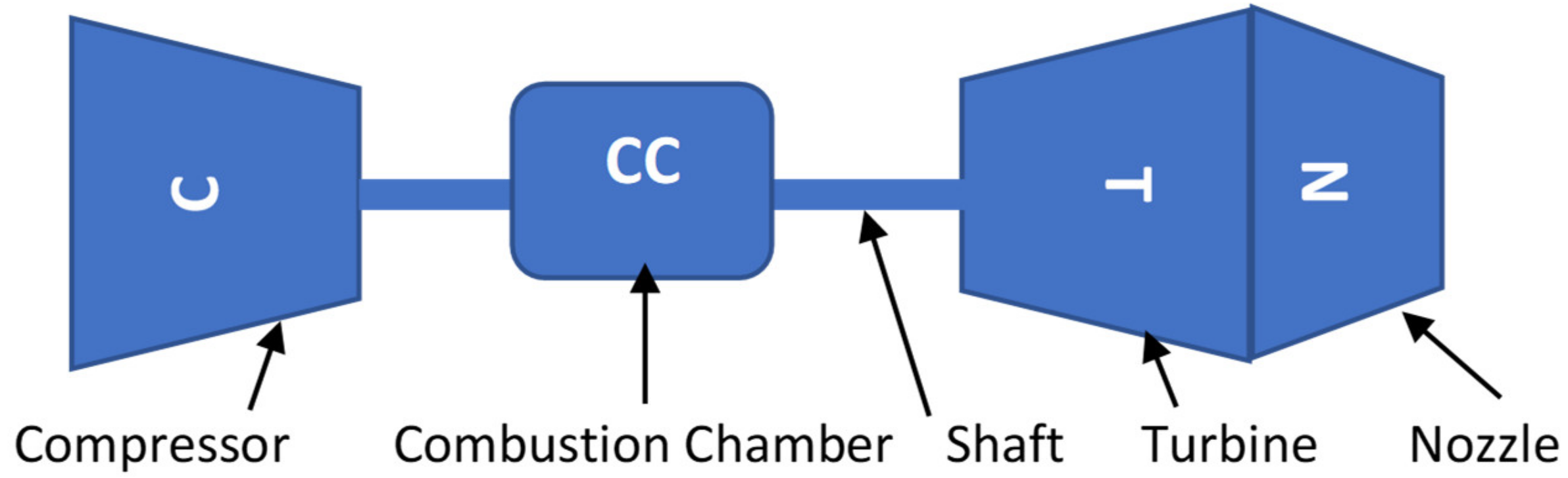
Without loss of generality, a single-spool turbojet engine (
Figure 1) was selected as a case study in this paper. This engine has an axial three-stage compressor, an annular combustion chamber, and an axial one-stage turbine. The geometry structure of this engine is fixed and therefore applied fuel flow to the combustion chamber is the only parameter that can be used as the control variable. The GTE control system is required to meet the engine thrust regulation and safety constraints simultaneously. As mentioned earlier, the two different structures for the controller that have been selected for design, simulation, and implementation on the hardware in this paper are:
The controllers will then be implemented on the hardware and the results of real-time simulation will be compared to introduce the suitable fuzzy control algorithm for different applications.
2.1. Pure Fuzzy Controller (PFC) Design
The main idea in this strategy is to use the fuzzy rules to satisfy all engine control modes. In other words, this structure will benefit from the speed, the constraints satisfaction ability, and the flexibility from fuzzy nature. Former GTEs have been manipulated particularly by rotor speed management. This method could deal with engine limitations and be implemented by a hydro-mechanical controller. By emerging digital controllers, the rotor speed derivative (acceleration/deceleration) has been added to controllers’ structures as a control variable. Simultaneously speed and acceleration control has led to transient response improvement while engine functional characteristic reaching. As a sample, cold engine acceleration can lead to consuming more fuel for engine components warming and reducing the acceleration rate, while warm engine acceleration is smooth and quick. Rotor acceleration control provides stable acceleration that is self-governing from engine temperature situation. Besides that from the safety point of view, this method has avoided engines from aerodynamic instabilities like surge, rotor over speed, and turbine blades overheating. Respecting to this fact that the derivative part of a controller is more sensitive to rotor speed variation and has a proper time response in comparison with the integral controller part, and integrated signal hardware implementation was time-consuming for operation at HIL purpose, without loss of generality for our story approach this part of the controller was neglected and PD controller chosen for controller design. There is much evidence in scientific researches that illustrate the application of rotor speed and its derivative as control variables for GTEs controllers [
21].
The schematic of this type of controller has been shown in
Figure 2. As it can be seen in this figure, this controller has two input variables, route error (the difference between throttle command-power lever angle- or desired rotor speed and real rotor speed) and the derivative of this error. Both K1 and K2 coefficients are determined for normalizing membership function inputs, cause the acceptable determined range for these inputs is between −1 to 1, and they stand for mapping inputs to the range of acceptable membership function variables. Based on these inputs and the pre-defined fuzzy rules, the controller calculates transient fuel flow as the output. Moreover, as shown in
Figure 2, injected fuel flow to the combustion chamber will be achieved by adding steady-state fuel flow and transient fuel flow. The steady-state part of the fuel flow is calculated by a gain scheduling controller as a function of the engine rotor speed. This function could be derived from the engine performance simulation or experimental results.
It should be mentioned that for controller design, the Mamdani fuzzy inference engine and center of area (COA) defuzzification method are used. In addition, minimum stands for “AND” and maximum stands for “OR”. Moreover, for reducing the number of variables, calculation, and time expending for searching, the Gaussian fuzzy membership function is chosen. Each function has two tuning parameters and for PFC design seven linguistic variables were defined as
Table 2.
The definition of fuzzy rules needs to know the interaction between engine components and awareness of physical damages and probable aerodynamic instabilities that can occur while increasing and decreasing engine rotational speed. As an example, at the primary sharp acceleration time (PB) the transient fuel flow must be Z or PS because the existing engine components’ inertia can cause the turbine blade overheating. Also, at the primary sharp deceleration time (NB) the transient fuel flow must be Z or NS because the above-mentioned reason causes flame burnout.
Table 3 shows the fuzzy rules for the designed PFC.
In
Table 3 DeltaN stands for PLA-RPM (pilot lever angle and shaft rotational speed those were normalized), DeltaNdot stands for error derivative, and finally FMF stands for transient fuel flow changes. All inputs after receiving by controller were normalized and getting to PFC for calculating proper transient fuel flow and because of this reason all membership function’s inputs are between -1 and 1. The rules stated in
Table 3 are coming from experts’ knowledge and publicly available control laws for jet engine control systems [
22].
2.2. MIN–MAX Fuzzy Controller (MMFC) Design
Each GTE has three different control modes.
Steady-state control mode to meet pilot thrust level requirement.
Transient control mode to reach the required thrust in a proper time.
Physical limitations control mode to prevent the engine from damages and malfunctions (e.g., over-speed, over-temperature, surge, stall, etc.).
The idea of min–max controller presented by Kreiner. A and Lietzau. K is to design different control loops for each control mode and select the best control loop at each time step based on a pre-defined strategy to satisfy all engine control modes simultaneously [
23]. The schematic of a min–max control loop for a turbojet engine is shown in
Figure 3. As can be seen in this figure, the controller consists of four control loops as follows:
PLA control loop: this loop has to supply the pilot desired thrust in each situation.
Maximum speed limitation loop (MSLL): this loop is to prevent the engine from exceeding the rotor speed from the permissible amount. This control loop takes this responsibility to guarantee the integrity of the GTE.
Maximum acceleration limitation loop (MALL): at the primary acceleration time abrupt fuel injection is the main cause of aerodynamic instability (surge and stall). MALL loop protects the engine against this fault.
Maximum deceleration limitation loop (MDLL): at the primary sharp deceleration time control system must prevent fuel flow from abruptly reducing because the rotor inertia could lead to flame burnout. Therefore, the fuel flow reducing rate must be limited.
After designing the above-mentioned control loops, a pre-defined “MIN–MAX selection strategy” will select transient state fuel flow by using a selection algorithm between these four control loops to satisfy all engine control loops simultaneously. A simple min–max selection strategy for a single spool turbojet engine is as follow:
where WfPLA, Wfdec, Wfacc, WfNmax stand for fuel flow calculated by PLA, MDL, MAL, and MSL loops respectively. In addition, Wftr is the final transient fuel amount. In an acceleration operation, the min-select strategy will protect the engine from surge and over speed whereas, in a deceleration process, the max-select strategy will protect the engine from flameout. If the calculated pilot command transient (PLA) fuel does not exceed these limitations, it will be the winner of the min–max selection strategy. Otherwise, the fuel flow that imposes one of the limitations will be selected as the transient fuel flow in order to protect the engine against failure or malfunction.
The min–max control strategy performs very well in satisfying all engine control modes simultaneously. However, regarding engine nonlinear nature applying a linear controller at PLA loop will result in reducing the capability of input order tracing as well as losing the proper flexibility. This reason led researchers to design another form of MIN–MAX controller that fitted by a fuzzy controller for determining transient fuel at PLA, MALL, MDLL loops. Fuzzy min–max control parameters Variety cause to meet multi-control purposes.
Figure 4 shows the MMFC structure used in this study where all K1, K2, and K11 coefficients were determined for normalizing membership functions inputs, cause the acceptable determined range for these inputs are between −1 to 1, and they stood for mapping inputs to the range of acceptable membership functions variables. Again, for entering MIN–MAXs selection boxes outputs must be mapped so K22 and K3 were used for this purpose.
The MMFC design procedure is as follow:
PLA control loop design: as mentioned before, PLA control loop is to determine transient fuel for pilot command tracing in a proper response time. As shown at
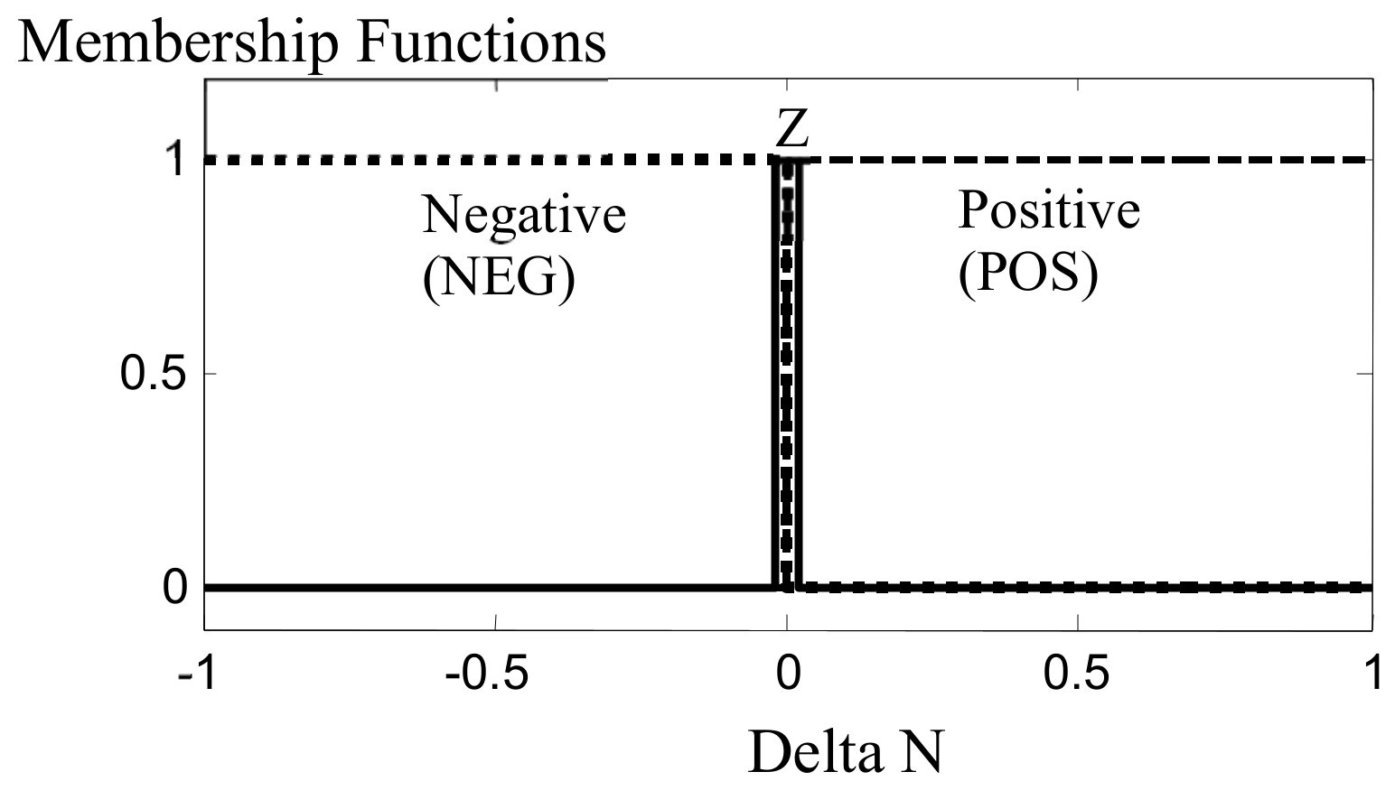
Figure 4, this fuzzy controller is a single input, single-output (SISO). The input is the error between the current engine rotational speed and the desired rotational speed (translated PLA to the engine rotational speed by using the thrust/rotational map of the engine) and the output is the transient fuel flow. For input and output, seven linguistic variables are determined with associated rules and membership functions as shown in
Table 4 and
Figure 5 and
Figure 6 (Delta N is PLA-RPM).
Fuzzy MALL and MDLL control loop design:
As instant fuel variation may cause aerodynamic instabilities like surge, stall, etc., MALL and MDLL control loops are to control acceleration/deceleration and to prevent the engine from exceeding its limits. For each loop, a SISO fuzzy controller is designed with three inputs and one output determined transient injected fuel. Rotor RPM error (Delta N), the difference between real acceleration with minimum (Ndot(min)-Ndot) and maximum (Ndot(max)-Ndot) allowed acceleration are three inputs as shown in
Figure 7,
Figure 8 and
Figure 9 and the transient fuel flow is the output.
The designed fuzzy rules are like the PLA loop as shown in
Table 5. As PLA loop symmetry and uniformity between membership functions and rules have caused linear relation between inputs and output in the MADLL (Maximum acceleration and deceleration) loops. Again, FMF is transient fuel flow.
It also should be mentioned that as MSLL loop is just to limit the maximum rotational speed of the GTE (and this value is constant for each engine), there is no need to manipulate it by fuzzy logic rules.
3. Hardware Implementation
After designing the PFC and MMFC, the implementation procedure will be described in this section in order to develop a HIL simulation platform to analyze the capabilities of the designed controllers in a real-time simulation feature. From implementation consideration point of view, selecting the proper hardware for real-world application is the main and the most important part of the controller manufacturing procedure. Chosen hardware must have an acceptable input reading speed, processing time, and resolution for outputs generation to be able to control the engine rapidly and correctly. For the GTE control problem, proper hardware must have minimum error and fault while reading engine rotational speed and PLA signals and producing the accurate fuel flow signal that should be injected into the engine to satisfy all engine control modes simultaneously.
Among different types of hardware, the AVR family has a lot of advantages including easy to program in C for most basic functions, adequate documentation, inexpensive, hobbyist friendly (parts in through-hole packages), nice peripherals (built-in oscillator, flash memory, onboard RAM, serial ports, ADC, EEPROM, etc.), low power consumption, and good cross-platform support. Therefore, the AVR Microcontroller (ATMEGA 32A) was chosen in this study. There is much evidence in the literature that confirms the use of ATMEGA family for controller hardware implementation because of the above-mentioned advantages [
24,
25,
26,
27,
28,
29,
30]. The procedure of implementation is described in detail in this section:
3.1. Experimental Apparatus
In order to design proper hardware for GTE fuel controller with HIL test, well communicating between hardware and MATLAB Simulink is mandatory. For this purpose, the PC serial port was used, and thus, sending and receiving data between hardware and MATLAB Simulink environment have become achievable. The MAX232 is an integrated circuit that converts signals from a TIA-232 (RS-232) serial port to signals suitable for use in TTL-compatible digital logic circuits. The MAX232 is a dual transmitter/dual receiver that is typically used to convert the RX, TX, CTS, RTS signals. Any communication between PC and hardware needs this chip. However, some modern computers don’t have a serial port. Therefore, a converter that can convert USB port to a serial port is also necessary. The used converter in this study is FT232 module. The FT232R is one of the latest devices to be added to FTDI’s range of USB UART interface integrated circuit devices. The FT232R is a USB to serial UART interface with optional clock generator output.
The main processor unit is from AVR family (ATMEGA32A). Each data value will be received by the microcontroller and after calculating and output generating, the result will be returned to the software by this AVR.
Figure 10 and
Figure 11 show the designed hardware schematic and its PCB (printed circuit board) separately. Components are generally soldered onto the PCB to both electrically connect and mechanically fasten them to it. This board is designed to simply achieve all requirements. It has one main processor (ATMEGA32), FT232 module to transferring data from PC to processor and vice versa, two capacitors, a resistor and regulator for power supply tuning, and a manual reset push button. After each process processor was automatically programmed for internal reset and it will be ready for another process.
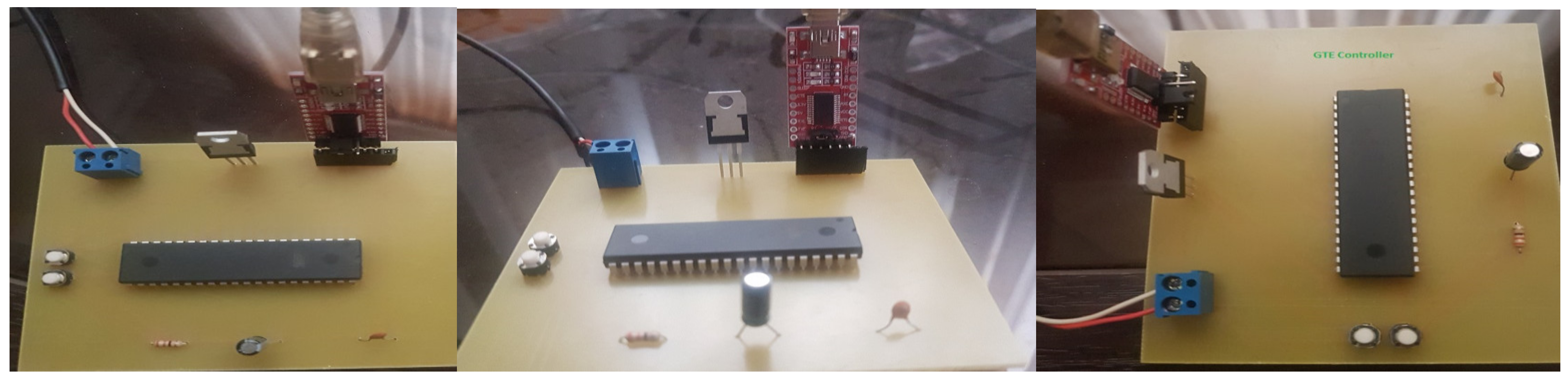
For communicating between the abovementioned hardware and PC (Simulink environment), required codes have been written in CODEVISION environment. As mentioned earlier, after correct communicating between hard and software achievement, each controller was programmed at hardware and tested for proper programming and validating the hardware implementation by MATLAB Simulink. The ongoing picture shows the GTE controller hardware.
Figure 12 shows the manufactured PCB in the real-world ready for control GTE. This PCB is the main GTE controller at our experiment and replaced with controller box in Simulink environment at hardware in the loop (HIL) test.
3.2. Initial Preparation
As shown in previous sections, fuzzy controllers take PLA and RPM as inputs and after calculation and execution of fuzzy rules, return the fuel flow signal as the output. This number is applied to the servo that controls engine fuel. The designed hardware can take PLA and RPM in the form of integer numbers (between 0–255) and output is a digital number between 0–255. An internal microcontroller clock was activated to counting transmission sensors pulses at a specified time for calculating the frequency and reading serial port for receiving PLA and engine rotational speed. The time-step is important because of calculating error derivative. The written codes for calculating time and receiving and transferring data are presented in the
Appendix A in detail [
Appendix A.1,
Appendix A.2].
3.2.1. PFC Controller Hardware Implementation
In order to implement the PFC, all seven Gaussian membership functions have been programmed in the Codevision environment. As an example, one of them is presented in the
Appendix A [
Appendix A.3]. It should be mentioned that the weighted average method is used for defuzzification. Computing output belonging value to membership functions was done with the center of the batch method as well [
Appendix A.4]. After gaining transient output, this value must be added to the steady-state value read from table that is programmed at hardware and this summation must be changed to a digital number that will be sent by the microcontroller.
3.2.2. MMFC Hardware Implementation
Implementation of the fuzzy min–max controller has three separate steps. The first two steps are for a fuzzy controller and the final step is the MIN–MAX loops programming. The first fuzzy controller has one input and fifteen Gaussian membership functions (PLA control loop fuzzification). The second fuzzy controller has two inputs (error and its derivative) and four membership functions (acceleration/deceleration control loop fuzzification), [
Appendix A.5,
Appendix A.6].
3.3. Hardware in the Loop Simulation
Hardware in the loop simulation method has wide application in dynamic systems simulations. In this method, some parts of modeling will be done in the software environment and some others will be programmed and implemented physically on the hardware. The designed hardware must be acted synchronously with software to guarantee the consistency of the results. For a control system test, there are two different options:
The controller could be modeled in the software to be running on target computer hardware while it is connected to your physical plant or system. (The target computer hardware acts as the controller.).
The other option is to implement the controller on the hardware, which can include production or embedded controls implementation, using a simulation of your plant or system. (Here, the target computer acts as a physical plant or system.).
In recent years hardware in the loop method was used in many pieces of research for testing physical elements act accuracy. Some of these researches are performed based on controller implementation [
31,
32,
33,
34], and in some of the engine and sensors are real [
35,
36,
37]. In this study, the controller is implemented as hardware in the real world and all other parts like engine and sensors were programmed at software.
Moreover, from a simulation speed point of view, the simulation could be run in the following features:
Real-time simulation refers to a computer model of a physical system that can execute at the same rate as actual “wall clock” time. In other words, the computer model runs at the same rate as the actual physical system. Real-time simulation and testing extend beyond simulation by verifying algorithmic design behavior while running models at required speeds, respecting precise timing requirements. The executing model is connected to sensors, actuators, and other hardware.
4. Results Analysis
In order to validate the accuracy of hardware implementation, the result of HIL simulations was firstly compared with a model in the loop (MIL) run. A MIL simulation is a technique used to abstract the behavior of a system or sub-system in a way that this model can be used to test, simulate and verify that model. The implemented controllers were simulated in both the HIL platform and MIL with the engine model to investigate the effectiveness and performance of each controller. The engine model is a block-structured model created and validated against experimental results. All details about the engine modeling and validation procedure could be found in [
18].
In order to simulate the dynamic behavior of the engine, the block-structured modeling approach has been used in this paper. These models consist of a linear dynamic part to simulate all engine lags and a nonlinear static part to simulate the relationship between the different engine parameters. The model parameters are usually tuned by the experimental results. There are three kinds of block-structure models, including Hammerstein, Wiener, and Wiener–Hammerstein models [
38].
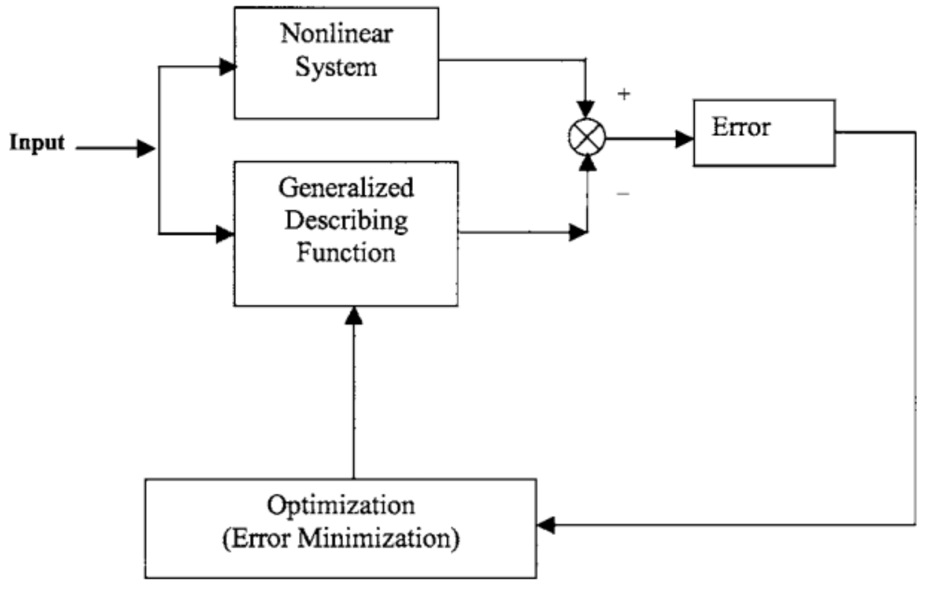
The novel generalized describing function (NGDF) is a recently proposed block-structured approach introduced by Lichtsinder et al. [
38]. The NGDF is based on the error minimization concept and the difference between the NGDF model and the models proposed by other researchers is that in NGDF the transfer functions between different inputs and outputs have an incremental form to enhance the accuracy of the model. The schematic of the NGDF model is shown in
Figure 13 to show that this method has the highest accuracy between the different block structures modelling approach, the jet engine is modelled using different modeling approaches, transfer function described in [
39], Wiener block structure described in [
40], and NGDF described in [
38]. The engine specification is shown in
Figure 14. The results are compared with the experimental results of the transient behavior of the engine in
Figure 15. As shown in
Figure 15, the NGDF is tracking the engine parameters with very high accuracy in both steady-state and transient operation. More details about the engine modelling, procedure, and used equations could be found in [
41,
42].
In order to carry on simulations, the PLA command has been varied with step changes as a function of time in order to test the capability of controllers in dealing with sudden changes and difficult working conditions.
Figure 16 and
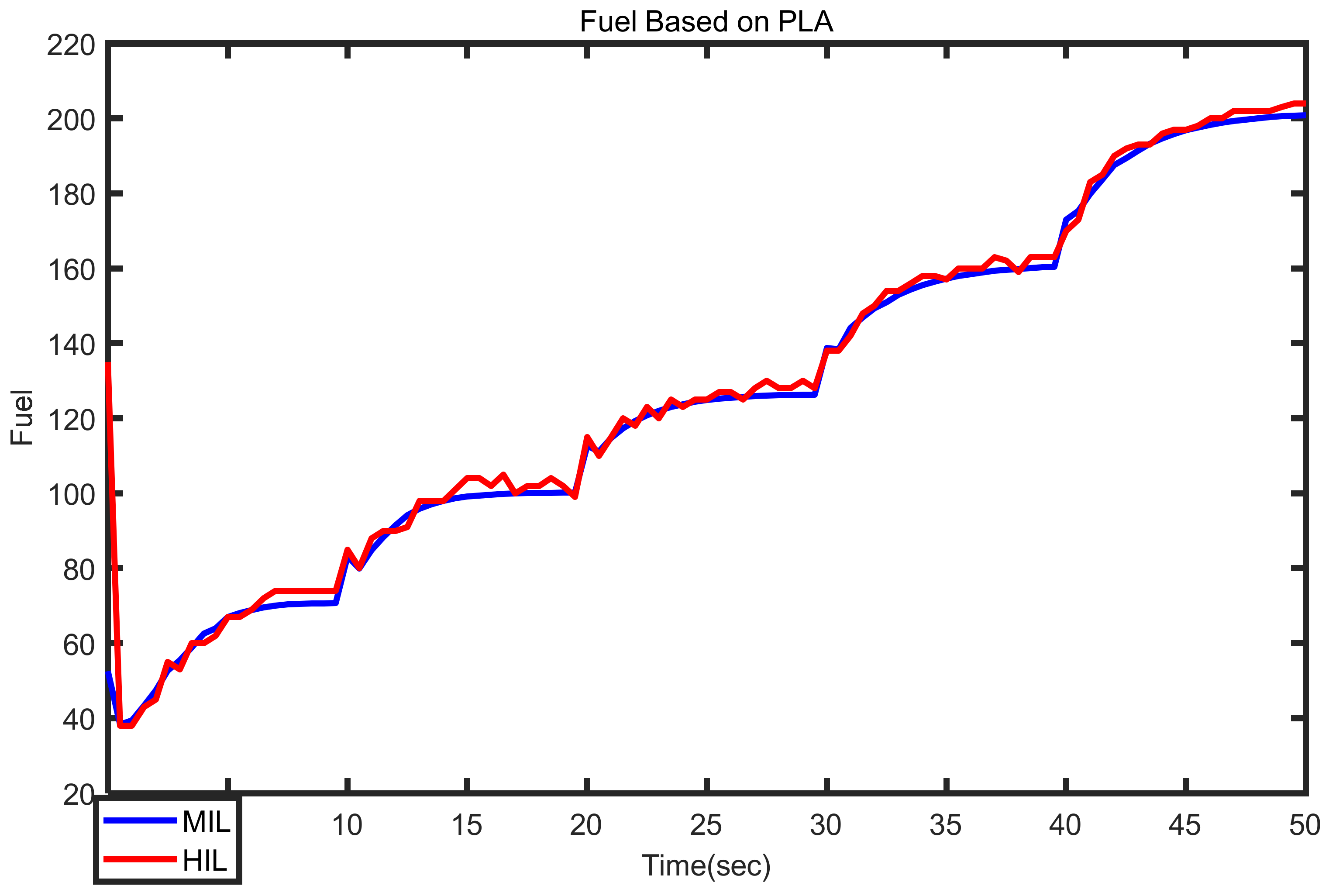
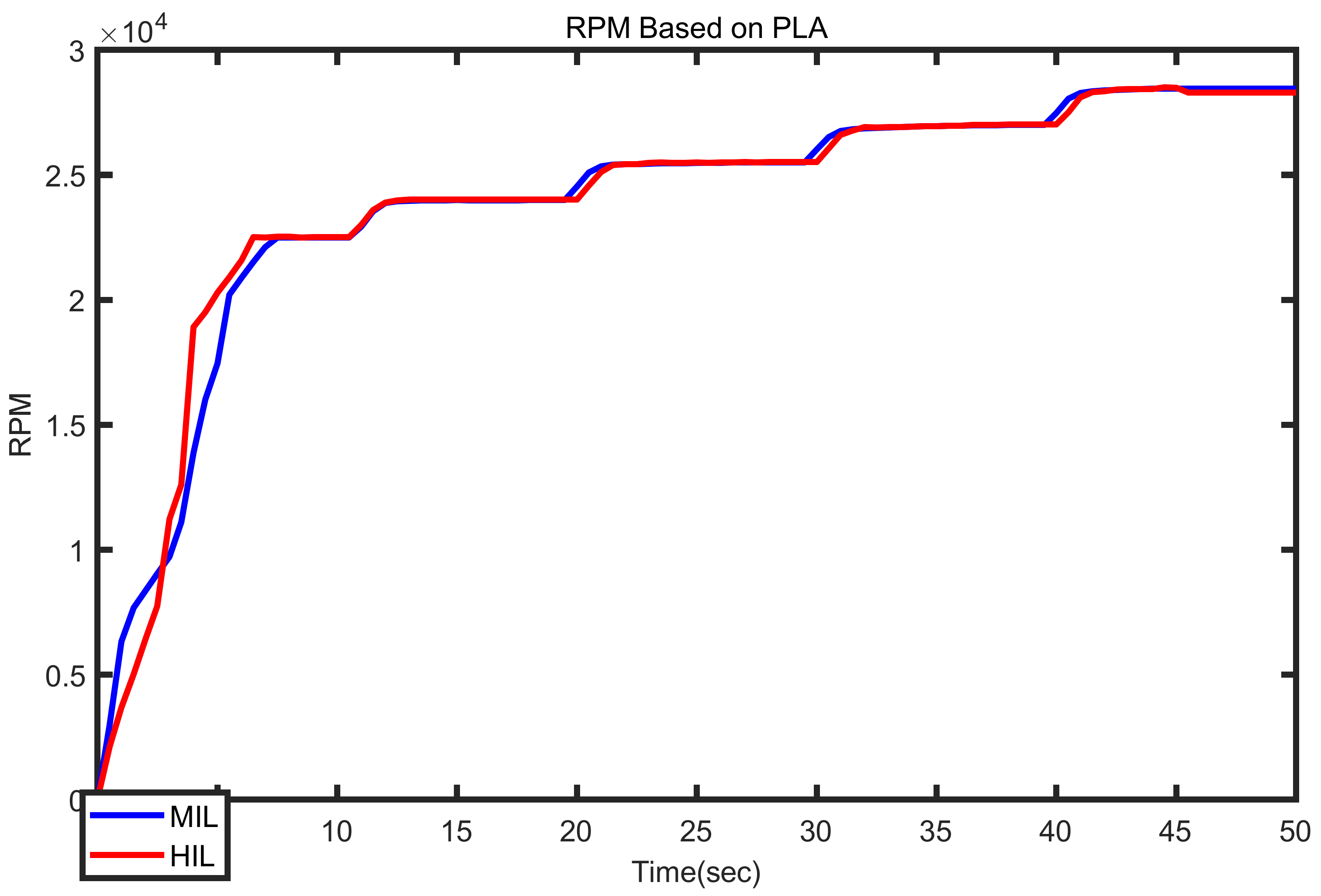
Figure 17 compare the MIL and HIL results for the PFC and
Figure 18 and
Figure 19 compare HIL and MIL results for MMFC. As can be seen in these figures, both controllers were implemented accurately and replicate the simulation situations without any steady-state or transient errors.
Moreover, the industrial min–max controller has also been implemented on the hardware in order to explore the effectiveness of the designed fuzzy controllers in satisfying engine control modes.
Figure 20 and
Figure 21 confirm the accuracy of the implemented min–max controller.
After confirming the validity of the implementation procedure, the dynamic behavior of the three controllers is compared.
Figure 22 and
Figure 23 compare the results of HIL simulations for PFC and MMFC and also the min–max Controller. These figures confirm that both fuzzy controllers are able to satisfy all engine control modes simultaneously without exceeding engine physical limitations.
Figure 22 shows that the PFC has a smaller response time than the MMFC. It means that this controller enables the engine for better maneuverability which is an important aspect for military and unmanned aerial vehicles (UAV) applications. Both controllers’ behavior is in very good agreement with the industrial min–max controller and this confirms the feasibility of the designed controllers for real-world applications. On the other hand,
Figure 23 shows that the MMFC has less fuel consumption in comparison with the PFC. It introduces this structure as a high potential candidate for applications where the fuel burn and specific fuel consumption (SFC) is more important (e.g., civil aircraft engines). Both fuzzy controllers perform better than the conventional min–max controller in terms of fuel economy.
Table 6 compares the response time and fuel consumption of the controllers in a one-minute simulation shown in
Figure 22 and
Figure 23.


