Article

Data Driven Modal Decomposition of the Wake behind an NREL-5MW Wind Turbine †

by
Stefania Cherubini
1,*,
Giovanni De Cillis
1,*,‡,
Onofrio Semeraro
2,
Stefano Leonardi
3 and
Pietro De Palma
1
1
Dipartimento di Meccanica, Matematica e Management, Politecnico di Bari, 70126 Bari, Italy
2
Laboratoire interdisciplinaire des sciences du numerique, CNRS, Université de Paris-Saclay, 91405 Orsay, France
3
Department of Mechanical Engineering, University of Texas at Dallas, Dallas, TX 75080, USA
*
Authors to whom correspondence should be addressed.
This paper is an extended version of our contribution to the 14th European Turbomachinery Conference, Gdansk, Poland, 12–16 April 2021.
Current address: Euro-Mediterranean Center on Climate Change Foundation, Ocean Predictions and Applications Division, 73100 Lecce, Italy.
Int. J. Turbomach. Propuls. Power 2021, 6(4), 44; https://doi.org/10.3390/ijtpp6040044
Submission received: 2 August 2021 / Revised: 22 October 2021 / Accepted: 19 November 2021 / Published: 25 November 2021

Abstract

:
The wake produced by a utility-scale wind turbine invested by a laminar, uniform inflow is analyzed by means of two different modal decompositions, the proper orthogonal decomposition (POD) and the dynamic mode decomposition (DMD), in its sparsity-promoting variant. The turbine considered is the NREL-5MW at tip-speed ratio λ = 7 and a diameter-based Reynolds number of the order 10 8 . The flow is simulated through large eddy simulation, where the forces exerted by the blades are modeled using the actuator line method, whereas tower and nacelle are modeled employing the immersed boundary method. The main flow structures identified by both modal decompositions are compared and some differences emerge that can be of great importance for the formulation of a reduced-order model. In particular, a high-frequency mode directly related to the tip vortices is found using both methods, but it is ranked differently. The other dominant modes are composed by large-scale low-frequency structures, but with different frequency content and spatial structure. The most energetic 200 POD modes account for ≈20% only of the flow kinetic energy. While using the same number of DMD modes, it is possible to reconstruct the flow field to within 80% accuracy. Despite the similarities between the set of modes, the comparison between these modal-decomposition techniques points out that an energy-based criterion such as that used in the POD may not be suitable for formulating a reduced-order model of wind turbine wakes, while the sparsity-promoting DMD appears able to perform well in reconstructing the flow field with only a few modes.

1. Introduction

Low-dimensional models based on modal decomposition of complex flows are often sought in many different fields and among those in wind energy. The orthogonality of the resulting modes makes the proper orthogonal decomposition (POD) the commonly chosen basis for the formulation of a reduced-order model (ROM). In the wind-energy field, POD was at first applied to two-dimensional data. Andersen et al. [1] applied this modal decomposition to planes perpendicular to the streamwise direction of large eddy simulations (LES) of the flow impinging on an infinite series of rows of wind turbines, each one consisting of three turbines modeled by the actuator line technique. Bastine et al. [2] applied two-dimensional POD to the case of a single wind turbine, impinged by a turbulent neutrally stratified atmospheric boundary layer. POD analysis was then applied to three-dimensional flow fields behind a wind turbine array by VerHulst and Meneveau [3], both in the presence and in the absence of atmospheric turbulence. Hamilton et al. [4,5] used POD applied to velocity measurements for investigating wake interaction and recovery dynamics in different wind turbine array configurations. More recently, Hamilton et al. [6] applied POD to LES data in order to construct a ROM of turbine wakes using polynomial reconstruction based on POD modes. Among others, Fortes-Plaza et al. [7] developed a ROM based on POD of LES data of yaw-controlled wake-interacting wind turbines. Very recently, De Cillis et al. [8] used POD analysis of LES of the flow behind a model wind turbine to determine the effect of the tower and nacelle on the development of coherent structures linked to given instability mechanisms within the flow.
POD is extensively used in the analysis of complex flow fields as it provides a finite set of orthogonal modes whose linear combination optimally reconstructs the energy of a set of stochastic flow data. However, in some particular cases, the most energetic POD modes may not be dynamically relevant; therefore, the selection of a low-dimensional basis for the realization of a reduced-order model may be not trivial [9]. In fact, POD ranks the modes depending on their energy, where the most energetic modes are often characterized by large-scale coherent structures which, in some cases, may not be the most dynamically relevant. Moreover, POD modes represent statistically steady structures, thus being unable to describe transient states which might arise from the interaction of the flow field with environmental disturbances, such as atmospheric turbulence. Finally, POD modes have a non-trivial temporal evolution, being composed by several temporal wavenumbers, while in some cases it can be interesting to capture structures characterized by a given frequency that can be more easily associated with well-defined physical processes (for instance, the wake meandering) or instabilities.
Another data-driven modal-decomposition technique that has all these capabilities and gained popularity in the last ten years is the dynamic mode decomposition (DMD), introduced by Schmid [10]. This technique finds eigenvalues and eigenvectors of a linear operator approximating the nonlinear dynamics embedded in the data sequence and it has been recently exploited for the formulation of ROMs of wind turbine relevant flows. Iungo et al. [11] realized a reduced-order model of wind turbine wakes based on the dynamic mode decomposition of LES flow data of wind turbines operating under different operational regimes. Le Clainche et al. [12] used the dynamic mode decomposition of LIDAR measurements to build a reduced-order model of the wind velocity upstream of a horizontal axis wind turbine. DMD modes are usually ranked according to their amplitude at the first snapshot of the data sequence. Such a criterion for the selection of a limited subset of dynamic modes can lead to poor quality of approximation of numerically generated snapshots and, therefore, to poor predictive capability of low-dimensional models. For this reason, different variants of the standard algorithm, aiming at extracting a limited subset of flow features that optimally approximate the original data sequence, have been developed, i.e., the optimized [13] or the sparsity-promoting DMD [14]. In the present work we use, for the first time in wind turbine wakes characterization, the sparsity-promoting (SP) algorithm for ranking the most relevant DMD modes.
The novelty of the current work is, therefore, to provide a direct comparison of the dominant POD and SP-DMD modes in the wake of a wind turbine, discussing possible reasons for their similarities and discrepancies and their potential relevance for the development of ROMs. As discussed before, POD is well fitted for flows whose coherent structures are to be ranked in terms of their energy content. However, in some cases the energy content of the coherent structures is not a well-fitted criterion to accurately describe the dynamical behaviour of the flow, which can be better modeled using a decomposition ranking the temporal dominant frequencies in terms of amplitude, such as DMD. In the literature, a few examples of comparative analyses of the performance of these two modal decompositions for different flows can be found. Reference [15] presents a comparative analysis of the POD and DMD modes extracted from experimental measurements of a turbulent jet flow. In this particular flow case, the modes arising from the different decompositions bear many similarities and the main physical instabilities are easily identified using both methods. In Reference [16], both modal decompositions are used to study the complex turbulent flow around a wall-mounted finite cylinder at high Reynolds number. Both methods were able to capture dominant phenomena, mostly characterized by large energy content. However, POD was found to not clearly separate frequencies and scales, while DMD yielded the most relevant physical phenomena, with distinct frequencies and growth rates. In Reference [17], the most dominant flow structures of a simulated flow in the wake of a high-speed train model were extracted using both POD and DMD. Comparison between the modes from the two different decomposition methods shows that the second and third POD modes correspond to the same flow structure as the second DMD mode. More recently, the performance of these two methods have been compared for several flows [18], finding relevant differences depending on the selected flow case. In general, it was found that POD is able to correctly reproduce time-localized events, but produces a severe spectral mixing between different modes. Contrariwise, DMD allows for proper frequency identification but may yield poor convergence and redundancy in the spatial structures [18]. However, this comparison has never been assessed directly for the case of the flow behind a utility-scale wind turbine at realistic Reynolds number. This type of flow is characterized by coherent structures at different scales, where the largest, most energetic scales are not deemed to be the most dynamically relevant. Moreover, the interaction of the rotating tip vortices generated by the blades with the non-rotating ones, originated by the tower and the nacelle, might potentially lead to transient events within the flow that might not be accurately described by the statistically steady POD modes. Finally, DMD analysis might be better suited to describe typical phenomena at given frequencies, such as the wake meandering [19].
The present study is motivated by the need to clarify the connection and differences between DMD and POD modes, as well as their physical meaning and performance in reconstructing the flow field, for the flow behind a utility-scale wind turbine. In the present paper, we identify the most relevant coherent structures embedded in the turbulent wake flow developing downstream of the NREL-5MW wind turbine, using the two mentioned modal decompositions, addressing convergence, selection and physical interpretation of both POD and DMD modes. The flow is computed through large eddy simulation using the actuator line method to simulate the rotor and the immersed boundary method to simulate tower and nacelle. Coherent structures are isolated by means of the POD and the sparsity-promoting DMD. The results obtained with the two modal-decomposition techniques are compared and differences are highlighted, particularly in regard to a low-order representation of the wake. In conclusion, the DMD modes selected by the sparsity-promoting algorithm are found to be similar to the most energetic POD modes, but strong differences are found in their capability of reconstructing the flow field.

2. Methodology

The present study is based on the numerical simulation of the flow over a wind turbine using the LES approach. The large-scale structures of the flow are directly computed integrating the filtered Navier–Stokes equations, whereas the effect of smaller-scale structures on the resolved ones is modeled [20]. The governing equations for the filtered non-dimensional velocity, u = ( u , v , w ) T , and pressure, p, derived from the Navier–Stokes equations for incompressible flows read as follows:
u i t + u i u j x j = p x i + 1 R e 2 u i x j x j τ i j x j + f i ,
u i x i = 0 ,
where the subscripts i , j { 1 , 2 , 3 } indicate the streamwise, x, vertical, y, and transverse, z, directions, respectively, and R e = U D / ν is the Reynolds number, defined using the inlet velocity U , the rotor diameter D and the kinematic viscosity of the fluid ν . Throughout the paper, upper-case (respectively, lower-case) notation denotes dimensional (respectively, non-dimensional) variables. The subgrid-scale stress tensor, τ i j , is modeled using the Smagorinsky model with constant C S set to 0.17, about equal to the theoretical value typically used for LES.
Equations (1) and (2) are discretized using a finite difference scheme based on second-order centered discretization on a staggered Cartesian grid. Time integration is performed using a hybrid low-storage third-order accurate Runge–Kutta scheme [21]. The term f i in Equation (1) accounts for the aerodynamic forces per unit volume exerted by the turbine blades on the fluid via the actuator line method [22]. These forces are modeled making use of the lift and drag coefficients of the rotor blades, which are treated as rotating rigid lines divided into discrete segments. In each segment, given the angle of attack and the relative inflow velocity, the lift and drag forces per unit length are estimated and then spread on areas perpendicular to each segment using a Gaussian distribution kernel. The tower and nacelle are taken into account by using the immersed boundary method, which avoids the use of a body-fitted grid, reducing the computational cost of the simulations. In particular, the approach proposed in Reference [23] has been used.

2.1. Proper Orthogonal Decomposition

The proper orthogonal decomposition (POD) is a statistical numerical technique able to identify the most energetic coherent structures characterizing the flow. The method is based on the eigendecomposition of the two-point spatial correlation tensor C, where the eigenvectors represent the POD modes and the associated eigenvalues represent their energy. A discrete approximation of the tensor C can be obtained from data consisting of a large number M of snapshots of the flow field. The entire dataset is usually organized into a single matrix Q R N × M , in which each column is a single instantaneous velocity field, represented by N scalars. The two-point correlation tensor can be approximated by the matrix C R N × N , computed as follow:
C = 1 M Q Q T .
The eigendecomposition of C can be easily performed by computing the singular value decomposition of the snapshot matrix Q , divided by the square root of the number of snapshots M,
Q M = U S V T ,
where the columns u k of the matrix U of size N × M correspond to the POD modes, and the singular values squared correspond to the eigenvalues L of C , namely L = S 2 . The i-th snapshot can then be represented as a linear combination of POD modes:
q i ( t ) = k = 1 M a k ( t i ) u k
where the time coefficients of each POD mode, a k , are given by the rows of the matrix M S V T . In addition, due to the orthogonality of the modes, it can be shown that the time coefficients a k are uncorrelated at zero time lag:
a j a k ¯ = λ j δ j k
where · ¯ indicates the long-time average.

2.2. Sparsity-Promoting Dynamic Mode Decomposition

The dynamic mode decomposition (DMD), proposed by [10], is a data-driven technique which allows one to extract relevant flow features, namely the DMD modes, whose dynamics are governed by correspondent eigenvalues. The key steps of the basic algorithm are outlined hereafter.
As for the POD, a series of snapshots q i is collected at a constant sampling frequency. We assume that a linear time-invariant mapping A connects every pair of successive snapshots,
q i + 1 = A q i , i = { 0 , , M 1 } .
Using Equation (7) we can write:
Q 1 = A Q 0 ,
where Q 0 and Q 1 are:
Q 0 = q 0 q 1 q M 1 , Q 1 = q 1 q 2 q M .
The linear operator A , as suggested by [10], can be projected onto the r dimensional basis U consisting of the first r POD modes of the snapshots matrix Q 0 ,
Q 0 U S V T
A U F U T .
The dynamics in the low-dimensional subspace defined by the POD modes U is governed by
x i + 1 = F x i .
where x i is the projection of the snapshot matrix Q i in the low-dimensional subspace defined by the chosen POD modes, with i = 0 , M 1 . Dynamic modes are then extracted by computing the eigendecomposition of the matrix F :
F = y 1 y r Y μ 1 μ r D μ z 1 * z r * Z *
where y i and z i * are the right and left eigenvectors of F , which are scaled such that y i * y i = 1 and z i * y j = δ i j . Notice that the frequency of the DMD modes is then given by the eigenvalues μ i via the following relation: ω i = l o g ( μ i ) i Δ t . Therefore, using Equation (12), we can approximate the solution x n as follows:
x n = Y D μ n Z * x 0 = i r y i μ i n z i * x 0 = i r y i μ i n α i ,
where α i = z i * x 0 represents the component of the initial condition x 0 in the z i * direction. The snapshots can be approximated by mapping x n on the higher dimensional space C N ,
q n U x n = i r U y i μ i n α i = i r ϕ i μ i n α i ,
and can be seen, therefore, as a linear combination of the DMD modes ϕ i = U y i where α i is the amplitude of the corresponding DMD mode. Equation (15) can be written also in matrix form:
q 0 q 1 q M 1 Q 0 ϕ 1 ϕ 2 ϕ r P α 1 α 2 α r D α 1 μ 1 μ 1 M 1 1 μ 2 μ 2 M 1 1 μ r μ r M 1 V a n d
which highlights that the temporal evolution of the dynamic modes is governed by the Vandermonde matrix V a n d . Once the eigendecomposition of (13) is performed, the amplitudes’ vector α = α 1 α r T is computed solving the following optimization problem:
minimize α J ( α ) = Q 0 P D α V a n d F 2
The superposition of all the DMD modes, weighted by their amplitudes and evolving according to their frequency and growth rate, optimally approximates the data sequence. Moreover, the sparsity-promoting DMD aims at finding a low dimensional representation of the snapshots’ sequence in order to capture the most relevant dynamic structures. This objective is achieved in two steps. Firstly, a sparsity structure is sought, which achieves a user-defined trade-off between the number of modes and the approximation error, which depends on the sparsity parameter γ . This step is carried out by augmenting the objective function to be minimized with an additional term, card ( α ) , that penalizes the number of non-zero elements in the amplitudes’ vector α ,
min α J ( α ) + γ card ( α ) .
where γ is the parameter that influences the sparsity level, with higher values of the parameter promoting sparser solutions. Then the sparsity structure of the amplitudes’ vector is fixed and the optimal values of the non-zero amplitudes are calculated. The metrics defining the performance of the algorithm are the cardinality of the optimal amplitude vector card ( α ) and the performance loss, defined as:
% Π l o s s = 100 Q 0 P D α V a n d F 2 Q 0 F 2 .
For further details, the reader is referred to Reference [14].

3. Simulation Setup

The turbine considered in this study is the NREL-5MW with a diameter D = 126 m and hub height h = 87.5 m. The turbine is simulated at rated conditions with tip-speed ratio λ = 7 , which implies a constant dimensionless angular frequency of the rotor ω = 2 λ = 14 . The reference incoming wind speed at rated conditions is U = 11.4 m/s; therefore, the resulting diameter-based Reynolds number is Re 10 8 .
The size of the computational domain is 12.5 × 5 × 3 diameter units in the streamwise (x), vertical (y) and transverse (z) directions, respectively. The turbine is located at 4 diameter units from the inlet, where a uniform velocity U is imposed, and it is centered in the transverse direction. We should remark that in real-life applications the turbine is impinged by an atmospheric turbulent boundary layer, which can potentially affect the dynamics of the wake.
Therefore, the scenario we discuss can be considered representative of real-life applications for low values of the inlet turbulence intensity. At the outlet, a radiative boundary condition is employed, with uniform convection velocity c = 0.9 [24]. No-slip and free-slip conditions are imposed at the bottom- and the top-wall, respectively, whereas the lateral boundaries are periodic. The computational grid used consists of 2048 × 512 × 512 grid-points in x, y and z directions, respectively. The grid is uniform along the streamwise and transverse directions, whereas it is stretched in the vertical direction, with finer (uniform) spacing in the part of the domain where the turbine’s wake develops. The convergence of the numerical results with respect to the mesh has been assessed in Reference [8] for the mean flow. Concerning the POD and DMD modes, we have performed a sampling convergence study finding a moderate sensitivity of intermediate-frequency DMD modes, whereas low- and high- frequency DMD modes have shown robustness with respect to the sampling points.

4. Modal Decomposition of the Wake

Both modal-decomposition techniques used for identifying coherent structures in the wake are based on the same dataset. Snapshots of the velocity field are taken each 10° rotation of rotor, in a reduced three-dimensional subdomain enclosing the wake, whose extent is [ 4 12.4 ] × [ 0.7 0.63 ] × [ 0.8 2.2 ] in x, y and z direction, respectively. The entire dataset comprises 3052 snapshots; one of them is shown in Figure 1. The ensemble average of the snapshots, shown in Figure 2, is then subtracted from each snapshot.

4.1. POD Results

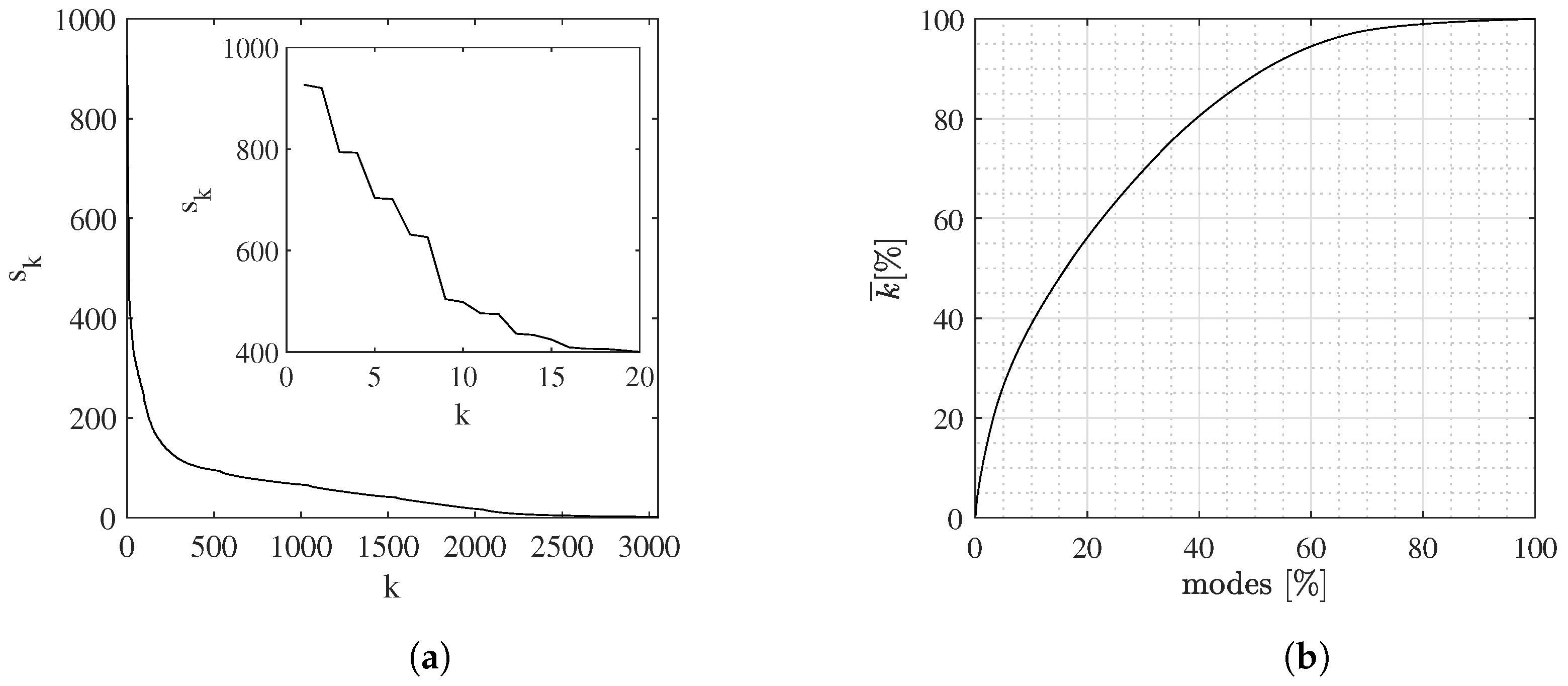
In Figure 3a, the distribution of the singular values is shown. A fast energy decay for the first 2–3 hundreds of modes can be observed; then, the slope of the curve decreases and a nearly null energy is reached for k 2500 . A closer look to the singular values for the first 20 POD modes highlights a step-wise distribution, suggesting that successive modes characterized by a similar energy are paired. Figure 3b shows the cumulative percentage distribution of turbulent kinetic energy versus the fraction of POD modes considered, computed as:
k ¯ [ % ] = k = 1 m s k k = 1 M s k × 100 m { 1 , , M }
modes [ % ] = m M × 100 .
A total of 50% of the turbulent kinetic energy is due to only 15% of POD modes (∼457 modes), and 50% of modes (∼1525 modes) accounts for about 90% of the turbulent kinetic energy.
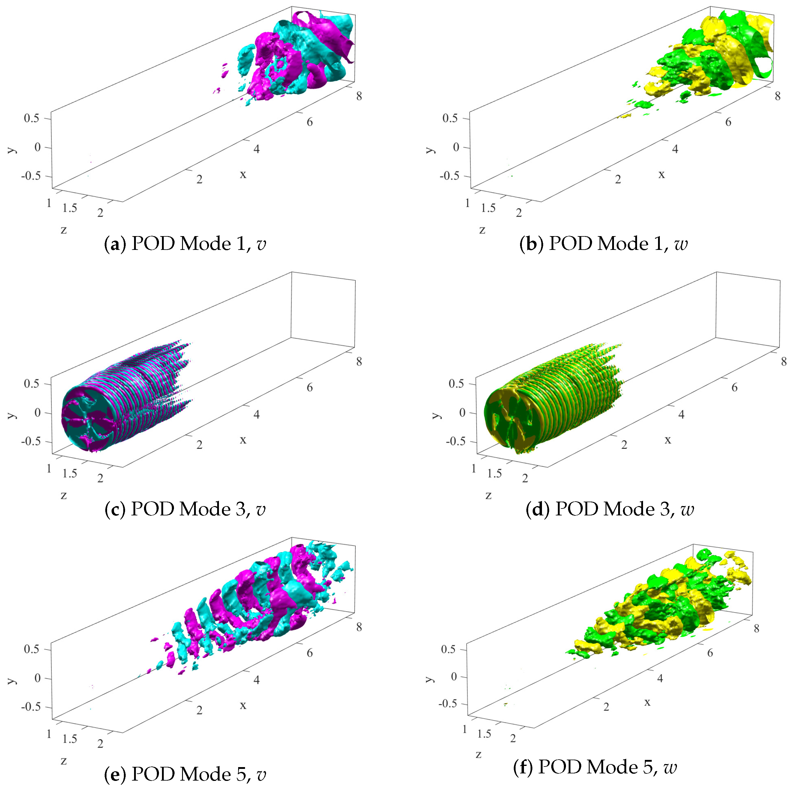
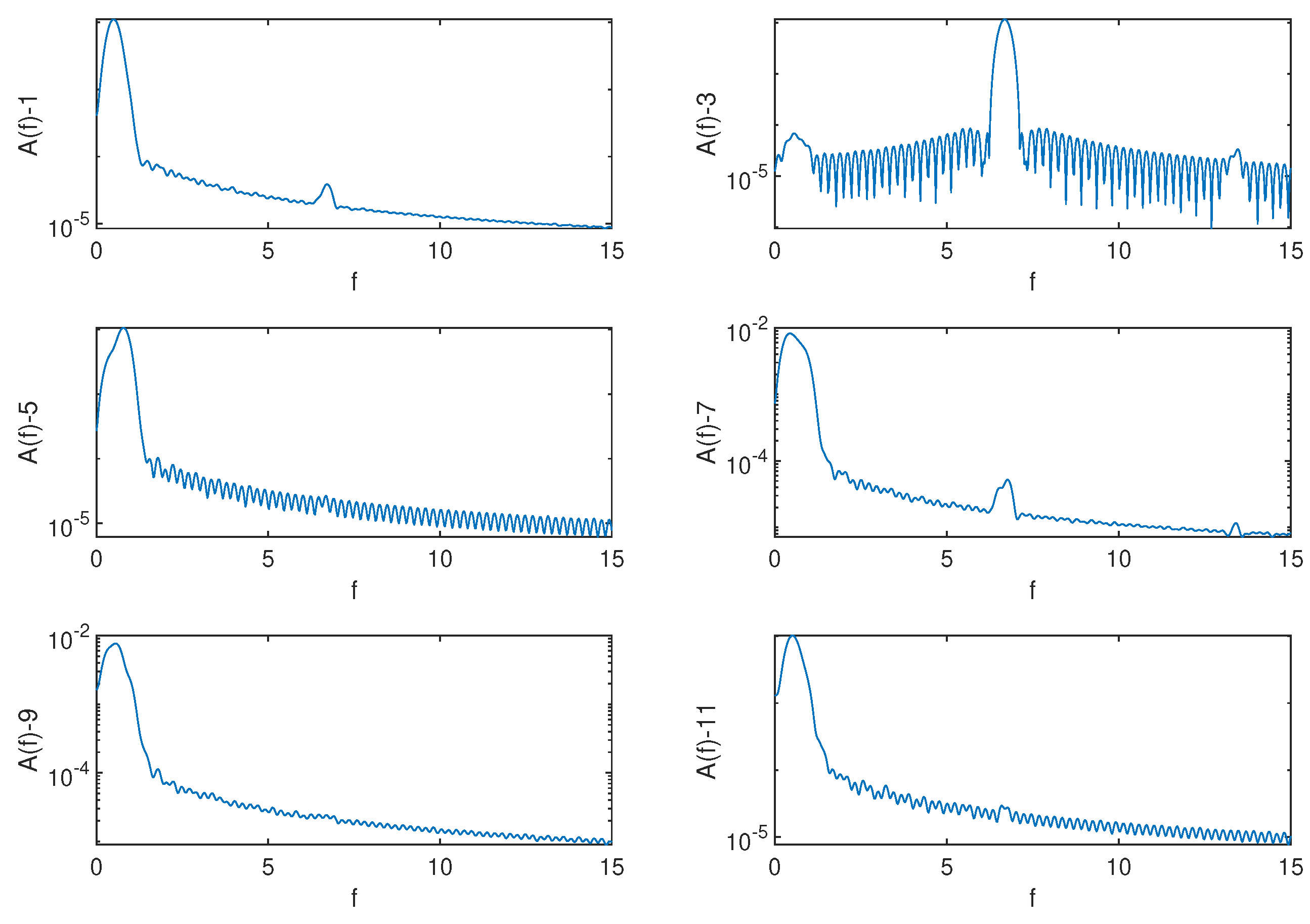
The most energetic POD modes are shown in Figure 4 (streamwise component) and Figure 5 (vertical and transverse components). The second pair, provided in Figure 4b and Figure 5c,d, clearly corresponds to the tip vortices, which are localized very close to the turbine. The remaining modes are mostly localized in the far wake and are all characterized by low-frequency large-scale coherent motions. In fact, in the region close to the turbine, the tip vortices quickly break down and their energy is redistributed towards the smaller scales, until reaching the dissipative range, where the very small eddies are dissipated. Thus, far from the turbine, where tip vortices have broken down, other low-frequency coherent structures emerge that can be linked to the instability of the mean flow or to the nonlinear interactions between the vortices released by the turbine. In the case under consideration, the observed large-scale structures can be linked to the vortices shed by the tower and nacelle, as observed by De Cillis et al. [8]. Fourier transform of the time coefficients a k ( t ) associated with the most energetic POD modes is provided in Figure 6. While the third mode, which is associated with the tip vortices, has dominant wavenumber ω 42 ( f 6.45 ), roughly corresponding to three times the angular frequency of the rotor, the other energetic modes are characterized by low-frequency oscillations in the range ω [ 2.44 4.58 ] ( f [ 0.44 0.73 ] ). However, Figure 6 shows that most of the POD modes are characterized by more than one frequency peak, showing a higher/lower frequency content which appears not to be merely due to the development of harmonics of the main frequency. This confirms the fact that POD does not allow to clearly separate frequencies and scales of the main coherent structures developing in the flow. The main temporal wavenumbers of the eight most energetic pairs are reported in Table 1, for further comparison with the DMD most relevant modes.

4.2. SP-DMD Results

The sparsity-promoting DMD has been performed on a subspace made of 251 POD modes, for increasing values of the sparsity parameter γ , in order to investigate the performance of the algorithm, as shown in Figure 7. It can be noted that the performance loss is not null, even for low values of γ , because the DMD is computed on the low-dimensional space defined by the first 251 POD modes. Notice that the first 251 POD modes allow a reconstruction of only ≈30% of the flow kinetic energy (see Figure 3). However, the same number of DMD modes leads to a loss in reproducing the whole velocity field of 20 % only (see Figure 7, showing the percentage of loss as defined in Equation (19)). Thus, when comparing the performance of POD and DMD, we will refer to the relative performance loss, computed with respect to the baseline value obtained when retaining all 251 modes used for the projection on the POD base (namely, 20 % P i l o s s ). In Figure 7, we can see that, for γ < 4 × 10 3 , approximately all 250 modes are retained, leading to a relative performance loss close to zero. For 4 × 10 3 < γ < 10 4 , the retained modes drop to ≈150, leading to a performance loss only slightly larger than the baseline value. Further increasing the sparsity parameter leads to a further drop of the number of selected modes, but at the price of a relative performance loss of more than 45 % when less than 100 modes are retained. This analysis shows that ≈200 modes are sufficient for reconstructing the flow field with an almost negligible relative performance loss. As a comparison, we can observe in Figure 3 that 200 POD modes lead to the reconstruction of only 20 % of the flow energy, while the same number of DMD modes leads to a performance loss of only 20 % . This clearly indicates that the kinetic energy may not be a relevant measure of the dynamical relevance of the flow structures for the considered flow. Thus, DMD modes appear to be better fitted for building reduced order models aiming at reconstructing the flow field with a small number of degrees of freedom.
For reducing the dynamics on a very low dimensional space, and comparing the relevant modes with the most energetic ones recovered using POD, in the remainder of the paper we select the value of sparsity-promoting parameter γ = 40,000. This particular choice, despite being characterized by a high performance loss, leads to the nontrivial selection of just 16 relevant dynamic modes. In the left panel of Figure 8, the eigenvalues μ of the linear operator F (see Equations (12) and (13)) are shown, along with the unit circle. The modes selected by the sparsity-promoting algorithm are marked with a black circle. As expected for a turbulent statistically stationary flow, all eigenvalues are very close to the unit circle, describing the periodic dynamics of the associated modes. It is noticeable, furthermore, the unbalance between high- and low-frequency modes, the high frequency ones being, essentially, harmonics of the tip vortices. The right panel of Figure 8 shows the logarithmic mapping of the eigenvalues, computed according to ω = l o g ( μ ) i Δ t where Δ t is the temporal separation between two consecutive snapshots and i the imaginary unit. Since the analyzed dataset is real, the eigenvalues with non-zero frequency form complex conjugate pairs, and so do the associated dynamic modes. Therefore, the 16 dynamic modes selected by the sparsity-promoting DMD consist of eight complex conjugate pairs. Frequencies and amplitudes of the selected dynamic modes’ pairs are summarized in Table 1, compared to the main frequencies of the most energetic POD modes.
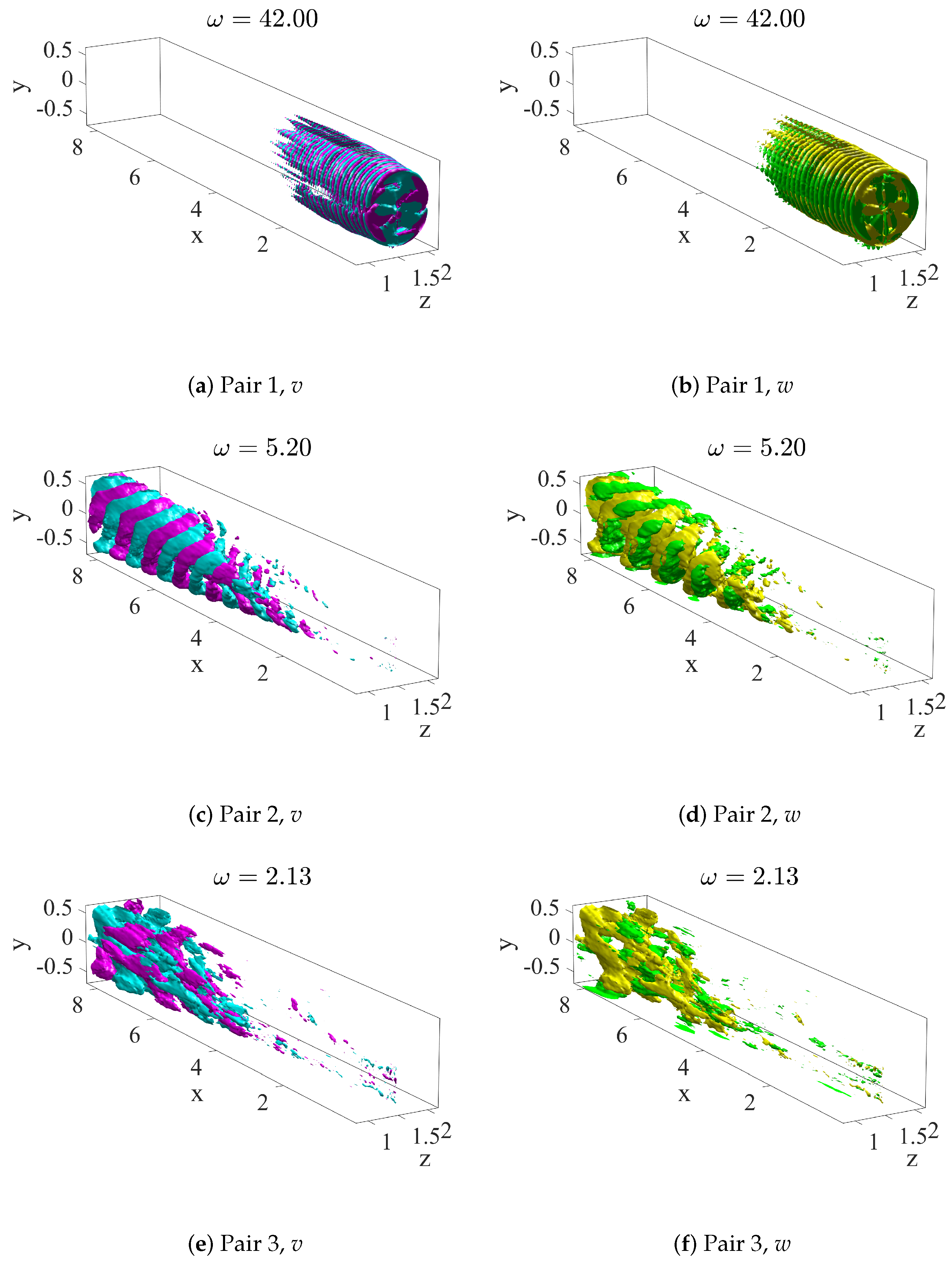
Figure 9 and Figure 10 provide the velocity components of the most relevant DMD modes, ordered by their amplitude | α | . It is apparent that their main structure is similar to that of the most energetic POD modes, despite the ranking is different and the associated frequencies are not exactly the same (except for the high-frequency mode). Among the modes selected by the SP-DMD, the ones that have the largest amplitude correspond to the tip vortices, as one can see in Figure 9a for the streamwise velocity and Figure 10a,b for the vertical and transverse components. Notice that this mode oscillates at a characteristic angular frequency ω = 42 , equal to three times the rotational angular frequency of the turbine. It is interesting to note that the POD ranked the mode associated with the tip-vortices as the second one in terms of energy, probably because it is characterized by smaller-scale structures than the other ones (large-scale structures bearing, in general, more energy than small-scale ones). The remaining selected modes are characterized by low frequencies and large-scale spatial structures, as can be observed in Figure 9b–h and Figure 10c–f. These low-frequency modes are probably linked to the interaction of tip vortices and tower vortices, as recently found by modal analysis of the wake of a wind turbine with and without tower and nacelle [8]. Compared to the POD modes, one can notice that these modes occupy a larger part of the domain, being characterized by smaller-scale structure in the near wake and large-scale structures in the far wake, while the POD low-frequency modes were found to be mostly localized in the far wake, probably due to the larger energetic content of large-scale structures which develop downstream once smaller-scale ones have dissipated. Moreover, in all the low-frequency DMD modes, one can clearly identify the footprint of the tower close to the inlet (see Figure 9b–h), which was seen only in POD modes 9 and 11. This direct connection with the near-wake small-scale structures is highlighted in Figure 11, providing the streamwise velocity contours of the most relevant DMD modes in two different wall-parallel planes. One can observe that the coherent structures of the DMD modes are almost equally distributed in the streamwise direction, except for the high-frequency mode which is mostly localized in the near wake, at least in the planes closest to the hub. Contrariwise, as shown in Figure 12, the most energetic POD modes are much more concentrated in the far wake (once again, except the high-frequency mode). Moreover, concerning the low-frequency POD modes, one can see a relevant scale separation between the structures closer to the hub (left frames) and those located closer to the wall (right frame). In particular, the coherent structures located farther from the hub have a much larger scale than those closer to it, probably being directly linked to the shedding of the tower (see De Cillis et al. [8] for a discussion of this type of POD mode). Instead, the coherent structures characterizing the DMD mode appear to maintain roughly the same wavelength, no matter the wall-normal position. It is worth to note that all the most energetic POD modes suffer from the same scale separation in the y and x direction, probably due to the fact that they are associated with more than one temporal frequency.
Finally, concerning the frequencies reported in Table 1, the DMD modes are characterized by slightly larger frequencies and are ordered with a different ranking with respect to the POD modes. In conclusion, the DMD modes selected by the sparsity-promoting algorithm are found to be structurally similar to the most energetic POD modes. Nevertheless, some non-trivial differences exist in ranking, frequencies and spatial structures, probably linked to the fact that DMD isolates structures associated with one frequency only, leading to relevant differences in the performance of the two sets of modes in reconstructing the flow field.

5. Discussion

The present work provides a numerical analysis of the dynamics of the wake developing behind the NREL 5-MW reference wind turbine, for laminar inflow conditions, using the proper orthogonal decomposition (POD) and the sparsity-promoting dynamic mode decomposition (SP-DMD) of the unsteady flow field. While POD provides a set of highly energetic, mutually orthogonal modes, these modes may not be the most dynamically relevant; therefore, the selection of a low-dimensional basis for the realization of a reduced-order model may be not trivial. On the other hand, DMD, in the sparsity-promoting variant, has the capability of selecting the most dynamically relevant motion, using a decomposition that ranks the temporal dominant frequencies in terms of amplitude. In the literature, some examples of comparative analyses of the performance of these two modal decompositions have been performed for different flows, showing the appropriateness of either of the two modal decompositions depending on the flow cases. However, such a comparison has never been assessed directly for the case of the flow behind a utility-scale wind turbine at realistic Reynolds number. In the present paper, the flow behind the NREL-5MW wind turbine was simulated employing an LES approach, in which the rotor blades are modeled using the actuator line method, whereas tower and nacelle are simulated using an immersed boundary method. The most energetic modes identified by the POD are mostly characterized by large-scale structures localized in the far wake, except for the second most energetic mode which develops in the near wake and closely resembles the tip vortices. Notably, 50% of the whole flow field’s turbulent kinetic energy is due to only 15 % of POD modes, namely ≈457 modes. However, ≈1525 modes are needed to account for about 90 % of the turbulent kinetic energy. Thus, using an energy-based criterion, it appears that a large number of modes is needed to appropriately reconstruct the flow field.
Attempting to reduce the degrees of freedom of the system, the sparsity-promoting DMD was performed on a subspace made of 251 POD modes. Depending on the value of the sparsity parameter, the SP-DMD selected different non-trivial subsets of dynamic modes that optimally reconstruct the entire data sequence. Comparing the reconstructed flow with the original one, it appears that for low values of the sparsity parameter the SP-DMD algorithm selects ≈200 modes, leading to a performance loss of ≈20% with respect to the reference snapshots. For high values of the sparsity parameter, the number of selected modes decreases considerably at the price of a larger loss. In all cases, the most relevant mode appears to be directly linked to the tip vortices, while the other most relevant modes are characterized by low-frequency oscillations filling a large part of the domain. While the coherent structures characterizing the DMD modes maintain roughly the same wavelength, no matter the wall-normal/streamwise position, the POD modes show a clear scale separation in the different spatial directions, probably due to the fact that they are associated with more than one temporal frequency. Moreover, the DMD modes are characterized by slightly larger frequencies and are ordered with a different ranking with respect to the POD modes.

6. Conclusions

Comparing the outcome of the DMD analysis with that of POD, we have to remark that a reconstruction using the most energetic 200 POD modes induces a loss of ≈80% of the flow kinetic energy, while reconstructing the flow field using the most relevant 200 DMD modes leads to a performance loss of only ≈20%. Despite the overall similarities between the two set of modes, the differences in ranking, temporal frequencies and spatial structures between the two modal-decomposition techniques points out that an energy-based criterion, such as that used in the POD, may not be suitable for formulating a reduced-order model of wind turbine wakes. Thus, sparsity-promoting DMD should be preferred for finding an optimal low-dimensional representation of flow data. Future work will aim at developing reduced-order models based on SP-DMD and evaluating their performance in different flow conditions.

Author Contributions

Data curation, formal analysis, draft preparation: G.D.C.; data curation, conceptualization, supervision, writing, original draft preparation, review and editing: S.C.; data curation, supervision, review and editing: O.S.; conceptualization, supervision, writing—review and editing: P.D.P.; conceptualization, supervision, review and editing: S.L. All authors have read and agreed to the published version of the manuscript.

Funding

This research received no external funding.

Institutional Review Board Statement

Not applicable.

Informed Consent Statement

Not applicable.

Data Availability Statement

Not applicable.

Conflicts of Interest

The authors declare no conflict of interest.

References

  1. Andersen, S.J.; Sørensen, J.N.; Mikkelsen, R. Simulation of the inherent turbulence and wake interaction inside an infinitely long row of wind turbines. J. Turbul. 2013, 14, 1–24. [Google Scholar] [CrossRef]
  2. Bastine, D.; Witha, B.; Wächter, M.; Peinke, J. Towards a simplified dynamicwake model using pod analysis. Energies 2015, 8, 895–920. [Google Scholar] [CrossRef] [Green Version]
  3. VerHulst, C.; Meneveau, C. Large eddy simulation study of the kinetic energy entrainment by energetic turbulent flow structures in large wind farms. Phys. Fluids 2014, 26, 025113. [Google Scholar] [CrossRef]
  4. Hamilton, N.; Tutkun, M.; Cal, R.B. Wind turbine boundary layer arrays for Cartesian and staggered configurations: Part II, low-dimensional representations via the proper orthogonal decomposition. Wind Energy 2015, 18, 297–315. [Google Scholar] [CrossRef]
  5. Hamilton, N.; Tutkun, M.; Cal, R.B. Anisotropic character of low-order turbulent flow descriptions through the proper orthogonal decomposition. Phys. Rev. Fluids 2017, 2, 014601. [Google Scholar] [CrossRef]
  6. Hamilton, N.; Viggiano, B.; Calaf, M.; Tutkun, M.; Cal, R.B. A generalized framework for reduced-order modeling of a wind turbine wake. Wind Energy 2018, 21, 373–390. [Google Scholar] [CrossRef]
  7. Fortes-Plaza, A.; Campagnolo, F.; Wang, J.; Wang, C.; Bottasso, C. A POD reduced-order model for wake steering control. J. Phys. Conf. Ser. 2018, 1037, 032014. [Google Scholar] [CrossRef]
  8. De Cillis, G.; Cherubini, S.; Semeraro, O.; Leonardi, S.; De Palma, P. POD-based analysis of a wind turbine wake under the influence of tower and nacelle. Wind Energy 2021, 24, 609–633. [Google Scholar] [CrossRef]
  9. Ilak, M.; Rowley, C.W. Modeling of transitional channel flow using balanced proper orthogonal decomposition. Phys. Fluids 2008, 20, 034103. [Google Scholar] [CrossRef] [Green Version]
  10. Schmid, P.J. Dynamic mode decomposition of numerical and experimental data. J. Fluid Mech. 2010, 656, 5–28. [Google Scholar] [CrossRef] [Green Version]
  11. Iungo, G.V.; Santoni-Ortiz, C.; Abkar, M.; Porté-Agel, F.; Rotea, M.A.; Leonardi, S. Data-driven reduced order model for prediction of wind turbine wakes. J. Phys. Conf. Ser. 2015, 625, 012009. [Google Scholar] [CrossRef]
  12. Le Clainche, S.; Lorente, L.S.; Vega, J.M. Wind predictions upstream wind turbines from a LiDAR database. Energies 2018, 11, 543. [Google Scholar] [CrossRef] [Green Version]
  13. Chen, K.K.; Tu, J.H.; Rowley, C.W. Variants of dynamic mode decomposition: Boundary condition, Koopman, and Fourier analyses. J. Nonlinear Sci. 2012, 22, 887–915. [Google Scholar] [CrossRef]
  14. Jovanović, M.R.; Schmid, P.J.; Nichols, J.W. Sparsity-promoting dynamic mode decomposition. Phys. Fluids 2014, 26, 024103. [Google Scholar] [CrossRef]
  15. Semeraro, O.; Bellani, G.; Lundell, F. Analysis of time-resolved PIV measurements of a confined turbulent jet using POD and Koopman modes. Exp. Fluids 2012, 53, 1203–1220. [Google Scholar] [CrossRef]
  16. Frederich, O.; Luchtenburg, D.M. Modal analysis of complex turbulent flow. In Seventh International Symposium on Turbulence and Shear Flow Phenomena; Begell House Digital Library: Danbury, CT, USA, 2011. [Google Scholar]
  17. Muld, T.W.; Efraimsson, G.; Henningson, D.S. Flow structures around a high-speed train extracted using Proper Orthogonal Decomposition and Dynamic Mode Decomposition. Comput. Fluids 2012, 57, 87–97. [Google Scholar] [CrossRef]
  18. Mendez, M.; Balabane, M.; Buchlin, J.M. Multi-scale proper orthogonal decomposition of complex fluid flows. J. Fluid Mech. 2019, 870, 988–1036. [Google Scholar] [CrossRef] [Green Version]
  19. Medici, D. Experimental Studies of Wind Turbine Wakes: Power Optimisation and Meandering. Ph.D. Thesis, Kungliga Tekniska Hogskolan (KTH), Stockholm, Sweden, 2005. [Google Scholar]
  20. Pope, S.; Pope, S.; Eccles, P.; Press, C.U. Turbulent Flows; Cambridge University Press: Cambridge, UK, 2000. [Google Scholar]
  21. Orlandi, P. Fluid Flow Phenomena: A Numerical Toolkit; Volume 55, Fluid Mechanics and Its Applications; Springer: Dordrecht, The Netherlands, 2000. [Google Scholar] [CrossRef]
  22. Sørensen, J.N.; Shen, W.Z. Computation of wind turbine wakes using combined Navier-Stokes/actuator-line Methodology. In Proceedings of the 1999 European Wind Energy Conference and Exhibition, Nice, France, 1–5 March 1999; pp. 156–159. [Google Scholar]
  23. Orlandi, P.; Leonardi, S. DNS of turbulent channel flows with two-and three-dimensional roughness. J. Turbul. 2006, 7, N73. [Google Scholar] [CrossRef]
  24. Orlanski, I. A simple boundary condition for unbounded hyperbolic flows. J. Comput. Phys. 1976, 21, 251–269. [Google Scholar] [CrossRef]
Figure 1. Streamwise velocity contours of a flow snapshot extracted from LES.
Ijtpp 06 00044 g001
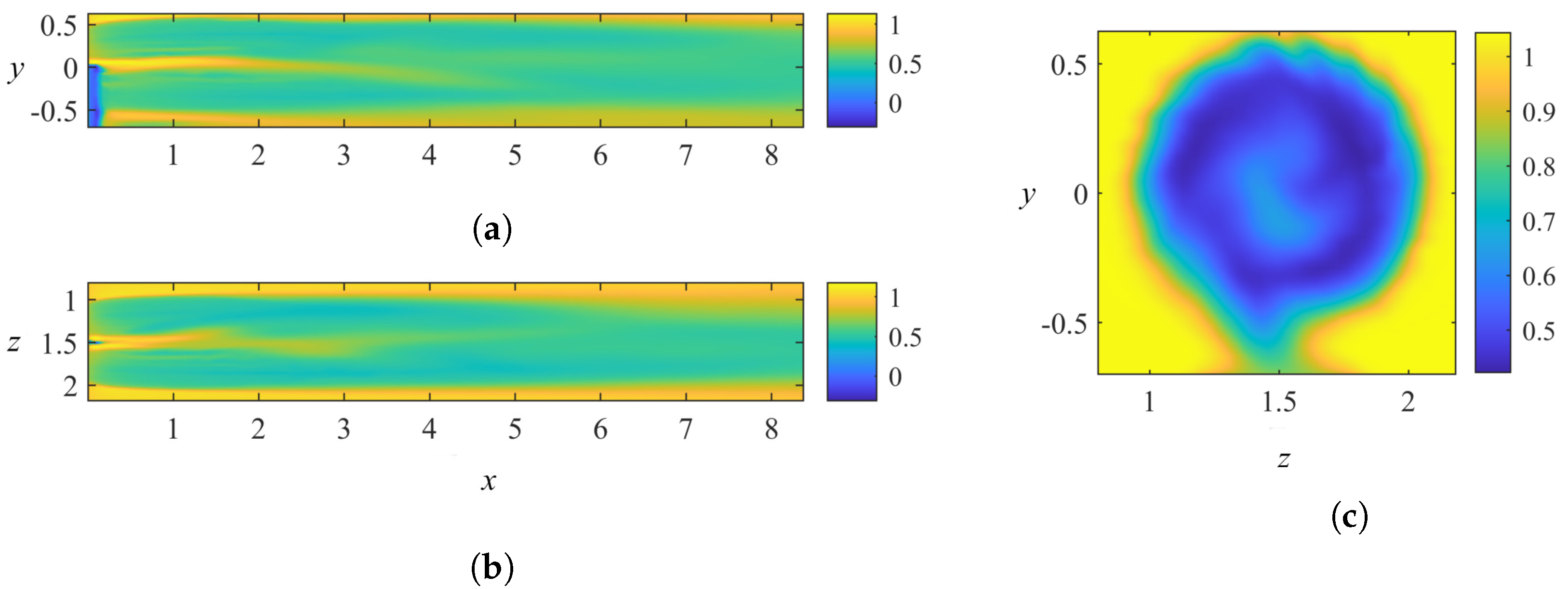
Figure 2. Streamwise velocity contours of the snapshots’ ensemble mean. (a) x y plane at z = 1.5 . (b) x z plane at y = 0 . (c) z y plane at x = 4 .
Ijtpp 06 00044 g002
Figure 3. (a) Singular values distribution with a close up for the first 20 modes. (b) Cumulative turbulent kinetic energy distribution versus the fraction of POD modes.
Ijtpp 06 00044 g003
Figure 4. Streamwise velocity iso-surfaces of the most energetic POD modes (red for u = 0.001 , blue for u = 0.001 ).
Ijtpp 06 00044 g004
Figure 5. Vertical (left) and transverse (right) velocity iso-surfaces of the most energetic POD modes (magenta/green for v , w = 0.0008 , cyan/yellow for v , w = 0.0008 ).
Ijtpp 06 00044 g005
Figure 6. Fourier transform of the time coefficients a k ( t ) associated with the most energetic POD modes shown in Figure 4.
Ijtpp 06 00044 g006
Figure 7. The sparsity level card ( α ) (a) and the optimal performance loss % Π l o s s (b) for different values of the sparsity parameter γ .
Ijtpp 06 00044 g007
Figure 8. Eigenvalues resulting from the standard DMD algorithm (red crosses) and the sparsity-promoting algorithm (black circles). The right panel shows the logarithmic mapping of the eigenvalues, ω = l o g ( μ ) i Δ t , where Δ t is the temporal separation between two consecutive snapshots and i the imaginary unit.
Ijtpp 06 00044 g008
Figure 9. Streamwise velocity iso-surfaces (red for u = 0.001 , blue for u = 0.001 values) of the real part of the eight dynamic modes’ pairs selected by the sparsity-promoting algorithm, ordered according to their amplitude | α | .
Ijtpp 06 00044 g009
Figure 10. Vertical (left) and transverse (right) velocity iso-surfaces (magenta/green for v , w = 0.0008 , cyan/yellow for v , w = 0.0008 values) of the real part of the most relevant three dynamic modes’ pairs selected by the sparsity-promoting algorithm, ordered according to their amplitude | α | .
Ijtpp 06 00044 g010
Figure 11. Streamwise velocity contours of the most relevant DMD modes on two y-constant planes.
Ijtpp 06 00044 g011
Figure 12. Streamwise velocity contours of the most energetic POD modes on two y-constant planes.
Ijtpp 06 00044 g012
Table 1. Frequencies and amplitudes of the selected complex conjugate dynamic modes’ pairs, computed with the standard and sparsity-promoting DMD.
R ( ω ) -POD R ( ω ) -DMD | α | (std. DMD) | α | (SP-DMD)
Pair 13.2642.014.3414.86
Pair 242.05.2011.399.55
Pair 34.582.138.548.53
Pair 42.233.929.267.89
Pair 52.442.307.507.80
Pair 63.762.968.267.48
Pair 72.644.256.396.02
Pair 81.133.584.224.06
Publisher’s Note: MDPI stays neutral with regard to jurisdictional claims in published maps and institutional affiliations.