Abstract
A numerical study was conducted to identify the mechanisms involved in the destabilisation of centrifugal compressors with vaneless diffusers. A stability analysis—carried out on the rotating and fixed parts of the studied machines—showed that the vaneless diffuser is a limiting component at a low mass flow rate. It was demonstrated that the reorganisation of stall patterns into recirculation in the inducer stabilises the impellers’ flow fields. As the destabilisation of vaneless diffusers has been a recurrent topic in the literature, many models have shown that it is the inlet-flow angle that drives the loss of stability. Models from the literature have estimated critical angle values using the geometry of the diffuser. Thus, for a given stage, expressing the diffuser inlet-flow angle as a function of the mass flow rate allows one to estimate its stability limit. However, this law needs to be calibrated to consider each compressor’s geometrical and aerodynamic specificities. This calibration can be achieved through single-passage steady simulations performed at stable operating points with high mass flow rates. With this methodology, a designer can estimate the stability limit of a centrifugal compressor with a vaneless diffuser from single-passage RANS calculations.
1. Introduction
Designing compressors with wide operating ranges remains a major challenge. In aeronautical and automotive fields, compactness is also a constraint to consider. Hence, most of the current turbochargers are centrifugal compressors. In addition, the need to maximise the operating range leads to the use of vaneless diffusers. At high mass flow rates, the choke limit is well-understood and well-predicted by designers. The low mass flow limit involving many complex unsteady loss mechanisms is more challenging. One of the main issues for designers is anticipating the surge-line position at the earliest design steps. In most cases, test campaigns or unsteady simulations of full compression systems are only feasible for the final design validation. That is why the implementation of a low-cost and fast predictive method of the stability limit is highly coveted by companies. To propose such a method, it is necessary to identify the destabilising mechanisms in the compressors.
Most research conducted in recent years on axial compressors, as summarised by Day [1], tends to show that the surge phenomenon is reached following the appearance of stall cells in the rotors. Although similar stall patterns are observed in centrifugal impellers, they do not have as much impact on the stage performance. As initially mentioned by Emmons et al. [2], the radial impeller stall may occur so mildly that it is undetectable without the aid of instrumentation. More recently, a stability map for the components of a centrifugal stage with a vaned diffuser was built by He and Zheng [3]. This map, based on unsteady pressure measurements associated with Fourier analysis, reveals that on many speed lines, the impeller turns unstable at the stall and then becomes stable again. With a further mass flow rate reduction, the vaned diffuser instability grows while the impeller keeps stable, leading the stage to the surge. In 2020, Zhang et al. [4] proposed a literature review about the vaneless diffuser stall. This summary of the state of the art highlights that—in centrifugal compressors—the vaneless diffuser stall is more harmful than that of the impeller because of the higher pressure fluctuation recorded. Hence, the surge limit is mostly linked for those configurations to the diffuser stability limit.
The structure of the vaneless diffuser allows for static pressure recovery by increasing the passage area with the radius. Thanks to this simple geometry, the vaneless diffuser stall has been extensively studied (analytically, experimentally, and numerically). All those works have demonstrated that the stall occurs when a critical inlet-flow angle is reached. Furthermore, a strong dependency of this critical flow angle on geometrical parameters has been identified. Several modelling works, from Jansen [5] to Guadagni et al. [6], provide estimations on the critical flow angle value depending on the vaneless diffuser geometry.
Usual approaches to determine the stability limit of a compressor are based on the evaluation of stability criteria or the identification of stall precursors through frequency analysis. These methods require high-frequency experimental measurements or unsteady full-annulus simulations predicting the flow topologies at low mass flow rates. Hence, they are generally found in academia and are hardly applicable to companies. Cheaper and faster alternatives are possible using simulations, which are performed during the design process. The present work responds to this need by the following:
- •
- Observing that a recovery of stability occurs during the impeller stall.
- •
- Confirming that vaneless diffusers are critical components for two different stages investigated, even if the impellers are stalled.
- •
- Proposing a low-computational cost methodology to predict the stability limit at low mass flow rates from data available during the design process.
First, the methods are reported. Then, a numerical analysis of the aerodynamic phenomena involved in the rotating and fixed parts stall is performed. The contribution of each component to the stage’s stability is investigated. In the third part, identifying critical elements for the compressor’s stability enables the proposal of a method based on a critical flow angle. This method predicts the surge limit from steady simulations of a single impeller passage at high mass flow.
2. Numerical Setup
2.1. Test Case Geometries
Two different centrifugal compressors are used to generalise the observed physics and test the predictive method introduced in this paper. Both were designed by Liebherr-Aerospace Toulouse. The first, named CMP-1, supplies air into an automotive fuel cell; the second, CMP-2, is integrated into an aircraft air-conditioning system. Even if present compressors are both radial, unshrouded, and equipped with vaneless diffusers, they remain different in design, as quantified in Table 1. By using Cordier’s formulation [7], it appears that the CMP-1 compressor has a lower specific speed () and a higher specific diameter () than CMP-2. Furthermore, the CMP-1 impeller was designed with splitter blades and has a tip clearance about two times higher than the one used in CMP-2 (relative to the blade span). Both tip gaps are constant from the leading edges to the trailing edges and occupy a significant part of the span. At rest, they are, respectively, 6% and 3% at the leading edges for CMP-1 and CMP-2. These high values, far from most of those generally observed in the literature, are required by the air-bearing technology used.

Table 1.
The compressors’ geometrical and operating parameters at design conditions.
The radius and width ratios show that the CMP-2 vaneless diffuser is shorter and wider than CMP-1. These quantities are, respectively, defined as and , where and h are the radius value at section i of the diffuser and the diffuser width at the inlet. Both compressors also differ in their volute designs, which reveal very different shapes.
Numerical simulations analysed in this paper were performed on the full-annulus configurations with volutes shown in Figure 1. Considering the similarities of the flow fields in compressors 1 and 2, the instantaneous visualisations illustrating phenomena described in this paper will only concern the CMP-1 compressor, which was already introduced in previous work [8].
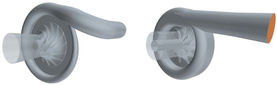
Figure 1.
Computational domains (left: CMP-1/right: CMP-2).
2.2. Flow Solver
All simulations were performed with STAR-CCM+ from Siemens. Considering the size of computational domains and the unsteady behaviour of near-surge flow fields, URANS modelling is the best compromise between accuracy and computational cost. The two-equation turbulence model from Menter [9] has been used due to its improved performance in flows under adverse pressure gradients and its applicability throughout the boundary layer. Moreover, its suitability in free-stream regions is ensured by the SST formulation. As noted by Durbin [10], the two-equation formulation tends to predict an unrealistic large growth of turbulent kinetic energy in stagnation points. That is why a correction, which limits the value of the turbulent kinetic energy production term, is applied to the present model. A coupled solver solves the continuity and momentum equations using an implicit second-order time-integration scheme. The number of physical time steps to discretise an impeller revolution is set to 860. In each of them, 12 inner iterations are carried out. Convective and diffusive fluxes are computed with an implicit second-order upwind scheme. Furthermore, the air is considered compressible under the assumption of the ideal gas, and its viscosity is estimated from Sutherland’s law.
2.3. Meshes
The finite volume formulation implemented in STAR-CCM+ is applied on polyhedral unstructured meshes associated with near-wall prism layer meshing. This layer sets the first cell size to ensure a normalised wall distance below and mostly between 0 and 0.6. Final meshes have been obtained through two steps. First, a mesh convergence in the impeller was performed with 30 cells in the tip clearance, a value commonly observed in the literature. After determining the number of cells needed in the impeller, a mesh convergence on the stator domain was achieved. The convergence was reached for approximately cells in impellers and cells in the vaneless diffusers and volutes. The interaction between rotating and fixed regions is modelled by a sliding mesh interface, considered the most accurate method.
2.4. Boundary Conditions
At the inlet of the domain, the absolute total pressure and the absolute total temperature are uniformly imposed with an axial flow direction. An analysis of the boundary conditions’ suitability to simulate centrifugal compressor flows in near-surge conditions was carried out by Kulak et al. [11]. It reveals that a mass flow boundary condition tends to over-stabilise the flow and, thus, stifle initiations of instabilities. Moreover, a pressure-imposed condition limits computed operating points to the zero slope section of the compressor characteristic. However, some compressors can operate in a positive slope section before reaching their stability limits. Thus, the present calculations are performed using a throttle law as an outlet condition. This condition updates the outlet static pressure at each time step according to the following relation:
where is the reference static pressure, is the throttle parameter, and is the mass flow rate through the exit section.
This boundary condition enables roaming the compressor characteristic from choke to surge by increasing the throttle characteristic slope value . The one-dimensional stability analysis from Greitzer [12] on a theoretical compression system shows that the stability limit can be reached by static or dynamic instabilities. Static instability occurs when the slope of the compressor characteristic becomes positive and too steep to intersect the throttle one. The dynamic instability is driven by the volumes integrated into the compression system and, thus, cannot be well described by a geometrically restrained numerical domain.
Although Pavesi et al. [13] have demonstrated that diffuser instabilities are sensitive to the leakage flow established between the impeller and the diffuser, no realistic boundary condition has been implemented to simulate it. Indeed, Fan et al. [14] pointed out that the intensity and the sign of the leakage flow may affect the onset and features of diffuser instabilities. Given that the behaviour of the flow passing through the seal is unknown for the studied compressors, the numerical setup used for this study is an ideal configuration without leakage flow.
2.5. Validation
One objective of this paper is to show that a low-cost methodology can be used to estimate the mass flow rate of the last stable operating point observed from full-annulus unsteady simulations. So, full-annulus simulations performed for the present work will be considered as the reference. However, it is still possible to validate the stability limit estimated from the URANS simulations by comparing it with measurements carried out at Liebherr-Aerospace Toulouse on the CMP-1 compressor. The test rig was equipped with three static pressure sensors, uniformly distributed along the pipe circumference, located after a duct bend downstream of the volute. The flow meter was located in the intake duct less than one meter from the compressor inlet. To reproduce experimental conditions, upstream and downstream ducts have been included in the numerical simulations. Thus, a numerical time-averaged outlet static pressure has been computed from three near-wall probes located at the exact measurement coordinates. Furthermore, numerical calculations have been set with the real experimental conditions to avoid the effects of a change in the Reynolds number that would directly impact boundary layer thicknesses. Hence, the comparison between experimental data and results from unsteady numerical simulations is based on a total-to-static pressure ratio normalised by the maximum measured value and plotted as a function of the corrected mass flow. This corrected mass flow rate is normalised by its expected value at choke conditions. The closest measured speed line to the one investigated in the present work corresponds to 97% of the studied rotation rate. Hence, the comparison between experimental and numerical data is performed at 97% of the rotation rate of interest.
Figure 2 shows a good correlation between CFD results and the experimental data for the operating points at low mass flow rates. The initiation of the positive slope section of the characteristic curve measured is well described by the numerical calculations. In addition, the stability limit of the CMP-1 compressor is reached at a similar mass flow rate for the simulations and the experiments. More precisely, the discrepancy between both is below 1% of the operating range. However, the operating points corresponding to the highest simulated mass flow rates reveal an increasing deviation. This trend suggests that the flow field at high mass flow rates is not well captured. In any case, the present study focuses on flow phenomena that develop at low mass flow rates. The good agreement with measurements near the surge line demonstrates the reliability of the present full-annulus unsteady calculations used to describe compressors’ destabilisation mechanisms.
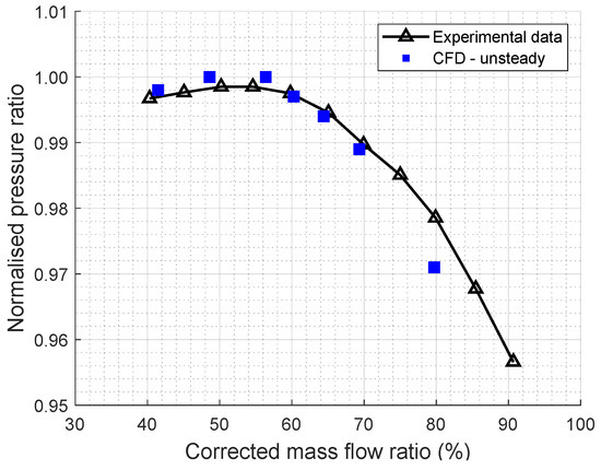
Figure 2.
Comparison of measurements and CFD results at 97% of the studied rotation rate (CMP-1).
3. Stall Mechanisms
Stall mechanisms developing along a speed line are illustrated through four operating points. These operating points are represented in Figure 3, which plots the compressors’ total-to-total pressure ratios and isentropic efficiencies as functions of the mass flow rate. Respective mean values at peak efficiency are used to normalise these quantities. OP1 is the maximum efficiency point, where the flow in both compressors is quasi-stationary and stable. OP2 corresponds to the stall onset at the impeller inlet. OP3 reveals a reorganisation of the stall pattern directly impacting the impellers’ performance. Finally, OP4 is the point at which any further throttling leads present compressors into a surge regime.
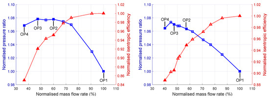
Figure 3.
Studied operating point locations on the compressors’ characteristic curves (from URANS calculations, left: CMP-1/right: CMP-2).
3.1. Impeller Stall
- Pre-stall disturbances in the literature.
Impeller stall mechanisms are generally due to an increase in the incidence caused by the mass flow reduction, inducing a boundary layer separation on the blade suction side. The interaction between the separated region and the incoming flow results in a Kelvin–Helmholtz instability inducing a tornado-like vortex shedding observed in a centrifugal compressor by Bousquet et al. [15]. In the past, Inoue et al. [16,17,18,19] demonstrated that in an axial configuration, this type of structure combines all the features of the appearance of short-length scale rotating stall cells. In some cases, the stall may also occur at the impeller inlet before the incidence causes the leading edge separation. Indeed, vortical activities associated with tip clearance flow that occurs near-stall were reported by Mathioudakis and Breugelmans [20], Mailach et al. [21] and März et al. [22] in axial configurations with wide-tip clearances. This flow phenomenon is called ‘rotating instabilities’. Massive structures belonging to the rotating instability family have been recently observed in centrifugal compressors with wide-tip clearances by Cao et al. [23] and Flete et al. [8]. Those authors describe vortex shedding trajectories from the suction side to the pressure side in the main blades’ leading edges region. Such behaviours associated with the significant sizes of these new vortices could disturb the flow field in the tip region and hence contribute to the impeller destabilisation. For the first time, this part identifies the role of these backflow vortices (BFV) in the stall process occurring at OP2. Then, the study of the operating points OP3 and OP4 will demonstrate that the stall pattern stabilises into an inducer recirculation for centrifugal compressors with wide-tip clearances and vaneless diffusers.
- Flow field at high mass flow rates.
At the present highest mass flow rate, OP1, the flow field in the impellers is mostly steady. This operating point located near the peak efficiency is considered a reference and will be used as a comparison for the following off-design point study.
- Inducer stall onset (OP2).
As initially described by Chen et al. [24] in an axial compressor and then by Flete et al. [8] in a centrifugal impeller operating in near-stall conditions, the addition of the radial gradient of tangential velocity under the tip leakage vortex and the near-shroud backflow leads to the emergence of backflow vortices (BFVs).
As demonstrated by Jeong and Hussain [25], vortical structures can be observed by plotting iso-surfaces. This quantity computed in the absolute reference frame is defined as the second eigenvalue of the tensor when sorted in ascending order, where E and are, respectively, the strain rate and spin tensors. Negative values of match vortex regions, while positive ones have no physical interpretation.
Figure 4 uses the criterion to highlight the BFV role in the inducer destabilisation occurring at OP2. Between and , a backflow vortex emerges from under a tip leakage vortex. Under the influence of the volute tongue potential effect, described in previous work [8], it reaches the next blade leading edge while similar structures in other blade passages still go through the clearance at downstream locations. In these circumstances, the following BFV is split into two parts: the downstream one will propagate in the passage, while the second will interact with the leading edge boundary layer. This interaction leads to a separation confined to the leading edge’s upper part. Due to the velocity difference, the interface between the main incoming flow and the low momentum flow from the leading edge boundary layer separation forms a severe shear layer. By a Kelvin–Helmholtz mechanism described by Pullan et al. [26] and Bousquet et al. [15], a tornado-like vortex develops from the blade suction side to the shroud. As shown in Figure 4 at and , this structure is periodically generated. By moving in the blade passage , the vortex subject to the reverse tip and main flow stresses evolves in another backflow vortex with a casing end migrating toward the next blade . Unlike present tornado vortices, the structures analysed by Bousquet et al. [15] do not necessarily require backflow vortex action to trigger the leading edge separation. In the previous work from Pullan et al. [26] on an axial compressor, these vortices are identified as “spike structures” and can simply be caused by an incidence excess without tip clearance. This author describes this topology as a starting point for spike-type rotating stalls.
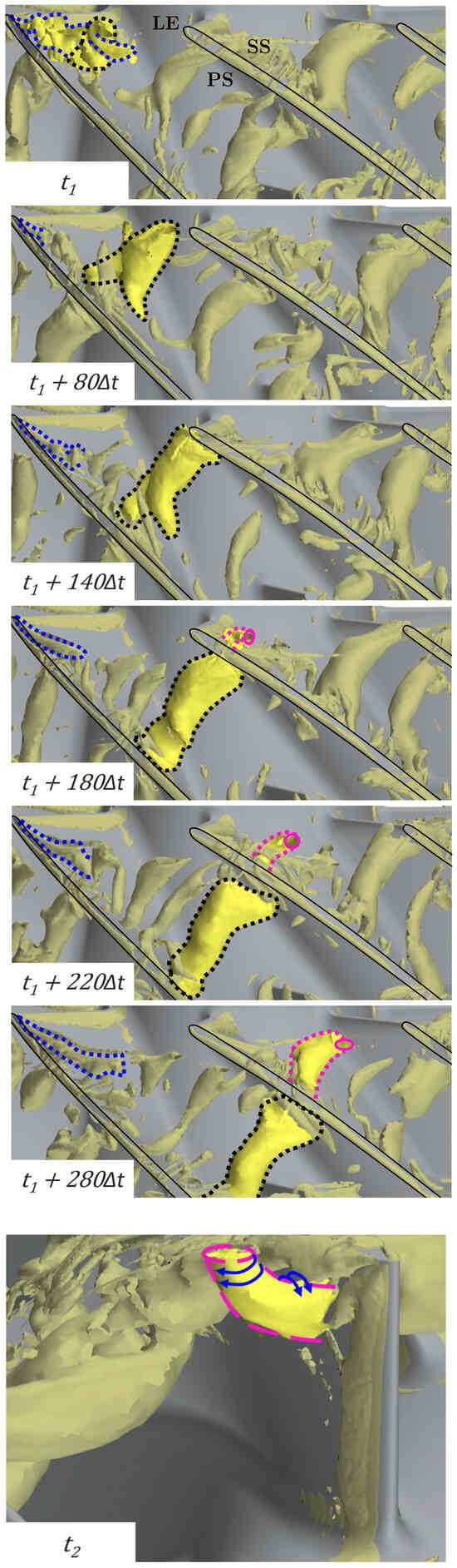
Figure 4.
Interaction between the backflow vortices and leading edges (OP2/CMP-1).
The backflow vortex area can occupy more than of the upper part of inducer passages deviating the incoming flow in the tip region. As illustrated by Figure 5, a focus on the plots corresponding to the operating points OP1 and OP2 reveals that such a phenomenon causes a significant increase in the incidence angle located around the tip regions. For the two compressors, these plots compare circumferentially averaged incidence profiles () for the operating points OP1, OP2, and OP3. A dedicated paragraph will analyse the lines associated with this last operating point. For both compressors, the incidence increases globally due to the mass flow reduction between OP1 and OP2. At OP2, the presence of the previously described near-shroud vortical structures causes a local increase in the incidence.
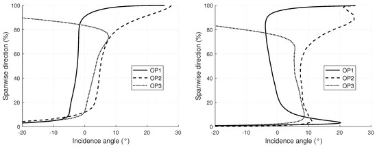
Figure 5.
Circumferentially averaged incidence profiles at the impeller inlets (left: CMP-1/right: CMP-2).
Some revolutions after imposing the throttle value associated with OP2, a first stall cell characterised by a negative axial velocity and a high vorticity magnitude appears near the shroud. To visualise the stall cell shape, Figure 6 shows instantaneous distributions of the axial velocity sign at the impeller inlet section. A black region corresponds to a negative value, while a white one is associated with the positive axial velocity of the incoming flow. At OP2, this part-span stall cell rotates continuously in the same direction as the rotor blades but at a slower speed (about 37% of the impeller rotation rate).
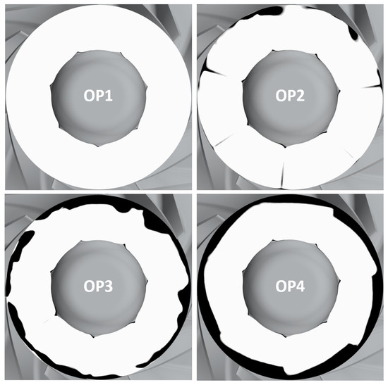
Figure 6.
Instantaneous visualisations of the axial velocity sign at the CMP-1 impeller inlet (white: /black: ).
- Stall pattern reorganisation (OP3).
By further throttling, the compressor reaches the OP3 operating point where a slightly different inducer flow topology develops. Indeed, at OP3, the negative axial velocity cell becomes larger until creating a zone covering the full circumference near the casing wall. This reverse flow that extends upstream reduces the available passage area for the underlying incoming flow. This mechanism directly implies an incidence decrease, shown in Figure 5, between the hub and the reverse flow for the two studied compressors. As a result, this blockage effect applied on a significant part of the inlet section (18% for CMP-1 and 22% for CMP-2) keeps the impellers in a stable state even at low mass flows. At OP4, flow topologies in both compressors remain the same with slightly thicker recirculated zones. Such behaviour has already been observed in automotive turbocharger centrifugal compressors with vaneless diffusers by Harley et al. [27]. They also observed that the recirculation zone produces a near-shroud aerodynamic blockage at the impeller inducer, changing the velocity triangle of the healthy flow.
The stall mechanism observed at OP2 leads to a slope discontinuity in the pressure rise of both impeller characteristics. However, unlike axial configurations, this type of rotating stall does not imply a large drop in pressure rise. This fact is consistent with the observations of Emmons et al. [2], illustrating that centrifugal compressors stall softly. Then, the impeller inlet recirculations observed at OP3 contribute to the centrifugal compressors’ robustness.
Understanding the mechanisms behind the establishment of this recirculation is a necessary step for expanding the operating ranges. A starting point could be the radial equilibrium in the meridional plane, which creates a pressure gradient from the casing toward the hub due to the impeller curvature. The resulting spanwise loading distribution might be the fundamental mechanism which prevents the radial extension of the recirculating zone.
3.2. Vaneless Diffuser Stall
Simultaneously with the impellers’ stall, the flow field in the vaneless diffusers becomes increasingly unstable from operating point OP1 to OP4. As detailed by Ljevar et al. [28], two flow topologies leading to two distinct destabilisation mechanisms are found in the literature depending on the geometry. The first one is associated with narrow vaneless diffusers and corresponds to the case where the boundary layers developed at the hub and the shroud are merged. Considering such flow structures, the three-dimensional wall-boundary layer instability drives stall development. The second case is associated with wide diffusers where the boundary layers on both sides remain separated by a core flow. In this case, the rotating stall onset is due to a two-dimensional core flow instability, and the boundary layers’ influence on the flow stability is negligible.
Abdelhamid and Bertrand [29] observed through experiments that the diffuser performance curve is continuous at the stall onset for width ratios higher than 0.09. On the contrary, for diffusers with width ratios lower than this value, they measured an abrupt performance drop. The authors have concluded that these two different behaviours at the stall are related to narrow and wide diffusers. Thus, the criterion to distinguish between both diffuser types is this threshold value of the width ratio.
In recent years, the identification of the core-flow instability mechanisms has been further refined. The studies of Fan et al. [14,30,31] conducted on a centrifugal pump have demonstrated that two distinct types of two-dimensional instability exist. The first occurs at low mass flow rates and corresponds to the instability leading to the rotating stall described for many years in the literature. These authors demonstrate through an energy budget that this core-flow instability arises from a combination of lift-up and streamwise deceleration mechanisms. The second core-flow instability identified occurs at higher mass flow rates, near design conditions. It is a large flow separation induced by the jet-wake pattern from the impeller outlet. Although this phenomenon causes a significant performance drop, it does not influence the surge onset. In addition, no similar flow structure has been observed during the analysis of the present compressors. Thus, this second core-flow instability occurring at high mass flow rates will not be further discussed.
The two present compressors belong to the wide vaneless diffuser family. Indeed, even if their width ratios are lower or equal to the threshold value proposed by Abdelhamid and Bertrand [29], their boundary layers remain separated by a core flow for all the stable operating points. To visualise the two-dimensional core flow instability development, meridional distributions of the radial velocity are shown in Figure 7 at each operating point for the CMP-1 compressor. These distributions taken at a circumferential position are coloured by the radial velocity sign. As with the axial velocity in impeller inducers, the negative radial component is associated with black zones while the positive one is white. The chosen angular position corresponds to the highest volute passage area unaffected by the volute tongue influence. As observed by Fujisawa et al. [32], evidence of destabilisation of the flow structure is intensified by the adverse pressure gradient that increases with the angle up to the volute tongue. That is why is the most favourable location to observe the core flow behaviour.
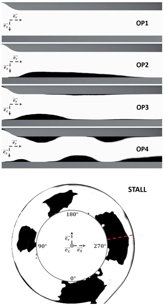
Figure 7.
Instantaneous visualisations of the radial velocity sign in the vaneless diffuser of CMP-1. (white: /black: ).
Instantaneous visualisation at peak efficiency (OP1) shows a positive radial velocity from hub to shroud throughout the studied section.
At OP2, a first boundary layer separation is observed at the hub due to the pinch influence. This steady zone extends along most of the diffuser length without interacting with the impeller trailing edges. A reattachment is observed further downstream. Such a flow structure is typical of radial source flows between parallel disks where wall friction and adverse pressure gradient coexist [33,34].
By further throttling, the CMP-1 compressor operates at a mass flow rate corresponding to OP3. In these conditions, the hub separation bubble extends axially, reduces radially, and migrates toward the impeller outlet. Furthermore, this boundary layer separation occurs periodically according to the mechanisms described by Weiss et al. [35]. At the shroud, the first evidence of a similar separation is observed, followed by a thinner one at the diffuser outlet on the hub side.
When the compressor operates at the lowest mass flow OP4, these separation zones grow in size and number, revealing an alternating pattern characteristic of the core flow destabilisation. Such a flow structure, featuring similar counter-rotating and alternating separation zones, has also been highlighted by Fujisawa et al. [32] and Agari et al. [36], who identify it as a starting point for rotating stall development. Despite this unsteady oscillating flow field, the operating point OP4 remains stable.
However, any additional throttling leads to the emergence of a four-cell rotating stall pattern brought to light by the last visualisation in Figure 7 at a 50% span. These cells propagate circumferentially at about 30% of the impeller rotation rate. According to the observations of Grapow et al. [37], based on PIV measurements, such rotating stall cells result from a merging process of the separation bubbles observed on the hub and shroud at OP4. In this configuration, the overall system is affected, and the surge occurs. Similar phenomena are observed from OP1 to OP4 in the second CMP-2 compressor. For each compressor, all along the speed lines, a continuous decrease in the static pressure recovery coefficient and an increase in the loss coefficient is observed.
3.3. Stability Analysis
At the last stable operating point OP4, the inducers host fully developed near-shroud recirculations while the core flows in the diffusers also become unstable. Both are loss mechanisms that can contribute to or be the cause of the surge initiation. A first-order stability analysis is performed to identify the phenomena responsible for the entry into the surge regime. According to Dean [38], the method used is based on the characteristic curve slopes of the different components. By considering the total-to-static pressure ratio for the impellers and the static-to-static for the stators, a logarithmic differentiation allows highlighting stability parameters , whose sign informs about the component’s stabilising or destabilising behaviour. A negative value is associated with a stable component having a stabilising effect on the stage. In contrast, a positive one is linked to an unstable component destabilising the compressor.
where , , and are, respectively, the stability parameters of the compressor stage, the impeller, and the stator. Seeking for readability, the volute contribution has not been isolated from that of the vaneless diffuser. This component contributing to the diffusion process has a monotonic behaviour that does not modify the trends dictated by the diffuser.
Stability parameter values are plotted as a function of the mass flow rate for the two present compressors in Figure 8. First, the impeller is becoming even more destabilised with the mass flow reduction and the rotating instability development up to the inducers’ stall onset at OP2. By further throttling, both impellers operate at stall conditions between OP2 and OP3, hence maximising the destabilising effect of the rotors. Then, the establishment of the previously described near-shroud recirculations at the impeller inlets stabilises the component, keeping the value in the stable zone. This stabilising trend is kept at OP4, where the blockage effect linked to these reverse flow zones becomes more intense. Simultaneously, the emergence of boundary layer separations in the diffusers observed from OP2 leads to a continuous increase in losses. From OP3 to OP4, where separation bubbles are established alternatively at the hub and shroud, these losses are such that values reach the positive zone. For the CMP-1 compressor, the value clearly follows behaviour, especially after the restabilisation of the impeller. This trend is not identifiable with the CMP-2 diagram stability. However, for both compressors, at the last stable operating point before the surge, OP4, the impellers have a stabilising effect on the stage while the stators are becoming even more unstable with the core flow destabilisation leading to the rotating stall onset. To conclude, even if both compressors have wide-tip clearances, the impeller stall is not responsible for the compressors’ loss of stability. It is the vaneless diffuser stability which sets the stage limit. Predicting its limit gives an accurate evaluation of the operating range.
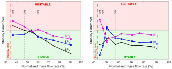
Figure 8.
Stability diagrams obtained from URANS calculations. (left: CMP-1/right: CMP-2).
Several works modelling vaneless diffuser flow fields have demonstrated that the stall occurs when a critical inlet-flow angle is reached. Considering the stability models developed by Ljevar [39], bringing critical flow angle values for the two studied vaneless diffusers, OP4 is the last operating point where the flow angles at the diffuser inlets remain above the critical values. In agreement with the models, any increase of the throttle parameter resulting in a decrease of the mass flow rate and, thus, a decrease of the radial component of the velocity leads to the destabilisation of the core flow and thus to the initiation of the rotating stall. Hence, the critical flow angle at the diffuser inlet () is the most relevant stability criterion for the two present compressors.
This criterion does not include any information on the jet-wake pattern established at the diffuser inlet. As mentioned above, the works of Fan et al. [14,30], conducted on a centrifugal pump, have demonstrated that such a flow structure may cause the emergence of a pulsating instability at high mass flow rates. Thus, the suggested stability criterion based on the mean inlet-flow angle is not able to predict the emergence of this kind of instability, which, to the authors’ knowledge, has never been observed in compressors. In any event, the stability of the two compressors studied is fully driven by the development of the core-flow instability occurring at low mass flow rates. Hence, the critical value of the diffuser inlet-flow angle remains a relevant stability criterion.
4. Predictive Method for the Stability Limit
4.1. Context
Predicting the operating range remains one of the main challenges for compressor designers. In an industrial context, the use of unsteady simulations of complete stages remains impossible in view of the associated computational costs. Similarly, the evaluation of the surge line based on experimental measurements is only envisaged at the end of the production process. Thus, one of the most common practices involves estimating the compressors’ stability limit at low mass flow rates as the point of divergence of RANS simulations. The problem is that these calculations, which are usually single-passage simulations, diverge as soon as the flow’s unsteady nature develops. Thus, the operating range is therefore often underestimated.
Recent work has proposed more accurate methods to predict the stability limit. One of the most successful is Haeckel’s model [40] based on Greitzer’s theoretical compression system model Greitzer [41]. Their approach combines analytical modelling of the surrounding system with steady simulations of the compressor stage. The coupling between the compressor map obtained through RANS calculations, the modelling of the system’s pressure losses, and the system stability criterion built by Greitzer made it possible to estimate the surge line location. However, manufacturers still find it difficult to apply this strategy. The simulations used to evaluate the compressor map and the pressure losses into the compressor stage are necessarily full-annulus with volute. In addition, the prediction accuracy will strongly depend on the number of operating points simulated close to the surge line. Finally, the surrounding system is not necessarily known during the initial design steps, making its modelling uncertain.
The latest trends in turbomachinery flow field prediction are moving toward artificial intelligence methods [42]. Training neural networks based on the CFD design of experiments or experimental datasets would make it possible to restore flow field structures occurring near the surge line without carrying out expensive calculations. This approach would allow the evaluation of local stability criteria, such as the diffuser inlet-flow angle value. However, constructing reliable datasets and implementing neural networks are currently too computational and engineering time-consuming for most industries.
This final section proposes a predictive methodology that can be integrated into a conventional design process without increasing design costs.
4.2. Adopted Strategy
By admitting that the compressor stability limit is associated with diffuser destabilisation, finding the last stable operating points is a matter of finding the conditions for which the diffuser inlet-flow angle reaches its critical value. It is possible to use models from the literature to estimate this critical value (). Senoo and Kinoshita [43,44,45] used the three-dimensional boundary layer theory while Abdelhamid [46] performed a two-dimensional, inviscid, and incompressible stability analysis to highlight the strong dependency of the critical flow angle on two geometrical parameters: the radius and width ratios. A few years later, numerical approaches were considered, such as the model of Gao et al. [47] based on wavelet neural networks or the one of Ljevar [39] for wide diffusers.
The challenge is, thus, to estimate the diffuser inlet-flow angle without using expensive calculations or measurements. In an industrial context, the usual design steps are to propose: (i) a first one-dimensional design followed by (ii) a three-dimensional geometry, which is (iii) evaluated through single-passage RANS simulations. Iterations occur until expected performances are obtained. Then, the resulting compressor is manufactured to start an experimental validation campaign. Incorporating a predictive methodology into this process without increasing the engineering cost is possible.
4.3. Model Implementation
The one-dimensional modelling of the inlet-flow angle is accessible from a simple analytical development. Figure 9 introduces the convention adopted in the present paper where the absolute flow angle () is measured from the tangential direction. In this representation, , , and are, respectively, the absolute, the relative, and the blade velocities. Hence, a mass flow reduction will decrease the value, and according to the literature, the diffuser flow structure is supposed to become unstable for values lower than . Finding the stability limit in terms of mass flow rate is a matter of finding the mass flow at which the value becomes smaller than . Simple development from the velocity triangle at the impeller trailing edge gives such a relation between the two quantities:
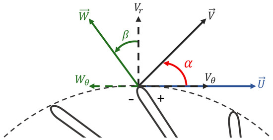
Figure 9.
Definition of the flow angles, and , from the velocity triangle at the impeller outlet.
Here, , , and S are the relative flow angle, air density, and passage area at the vaneless diffuser inlet.
The choice of these parameter values requires some averaging regarding the complex flow field at the impeller outlet vicinity. By considering an ideal case where there is no deviation, no near-shroud recirculation zone, and where the flow quantities would be axisymmetric and radially uniform, a first estimation of these parameters could be as follows:
- •
- •
- •
However, these values lead to an inaccurate prediction of the angle because they do not take into account the geometric (fillets, sharp trailing edge, etc.) and aerodynamic (blockage effect related to the near-shroud reversed flow) specificities of the compressor. Two fitting parameters, and , are used to fix that. is used to consider the geometrical specificities of the trailing edges and the slip phenomenon. On the other hand, corrects the density and effective passage area according to the flow field computed by the RANS simulations.
Calibration of these parameters by a least-squares method is possible with steady single-passage simulations without volute. Such calculations are already inserted into the standard designer workflow. Hence, using them to predict the stability limit does not increase the computational time and only requires some very easy post-processing steps. In practice, numerical inlet-flow angle values are computed from mass-averaged velocities according to Senoo and Kinoshita [43].
The well-known non-axisymmetric vaneless diffuser flow field induced by the volute presence [8,48,49] raises concerns about the suitability of the single-passage domain used to calibrate the model. Hence, diffuser-alone and diffuser with volute calculations have been used to assess the volute impact on the diffuser stall onset. These unsteady computations have been performed using boundary conditions similar to those used for the complete domain simulations. The first observation is that the stall occurs at the same inlet-flow angle as in full-stage simulations for both cases, with and without volute. However, the stall pattern related to these reduced computational domains differs from the reference four-cell one. Indeed, these domains host twelve-cell stall patterns in which cells are smaller and rotate at 51% of the impeller rotation rate. Hence, the diffuser and diffuser with volute test cases cannot restitute the exact configuration of the established rotating stall. However, the critical angle is the same, and it is the quantity of interest in the proposed context. Thus, for the studied compressors, the relevance of single-passage calculations without volute is ensured.
Steady simulations could be expected to directly provide values at near surge mass flow rate. Nevertheless, for operating points located between the zero slope section of the characteristic and the stability limit, RANS cases are numerically unstable because of convergence issues. This phenomenon can be explained by the strong unsteady nature of the flow field at low mass flow rates. Moreover, performing this kind of simulation remains more expensive than using the previously described extrapolation law. To ensure the reliability and suitability of such calculations, only operating points associated with mass flows higher than the one at peak efficiency are used. However, taking the choke point should be avoided, which involves a special flow topology very different from those met along the compressor characteristic curve. Given that the choke phenomenon occurs for normalised mass flow rates slightly higher than 160% and that peak efficiency corresponds to 100% (OP1), the steady simulations have been performed at about 120% and 140%.
The plot at the left of Figure 10 compares the angle evolution law calibrated from the single-passage RANS calculations with results from the full-annulus unsteady simulations with volute. On the whole, both are in good agreement near the calibration points. The change in the flow field structure induced by the mass flow reduction causes an increasing deviation. At OP1, the calibrated law overestimates the flow angle value of 0.2°. Such a small difference is insignificant. On the last stable operating point, OP4, the gap is maximum between both and is about 1.2°. Given the variation range of the angle values on this speed line, such a difference is acceptable, especially in a preliminary design context. As illustrated by the plot at the right of Figure 10, the distribution of the two RANS calculations has an insignificant effect on the calibration parameter values as long as the choke point is not used and the chosen points remain in the negative part of the efficiency curve. Furthermore, adding an additional calibration point (brown curve) does not improve the extrapolation accuracy.

Figure 10.
Extrapolation of the diffuser inlet-flow angle from single passage RANS calculations. (left: with the reference calibration points/right: with different calibration points).
The choice of the outlet boundary condition also affects the flow angle value estimated by the RANS calculations. Indeed, the short domain length may lead to a wrong adverse pressure gradient when a mass flow-imposed condition is used. Hence, only pressure-imposed conditions are suitable for this application. Moreover, the throttle law is not required for a steady and stable calculation. A usual constant outlet static pressure is sufficient.
4.4. Validation
Figure 11 compares the result of the proposed prediction calibrated with two RANS calculations (black squares) to the results obtained with unsteady full-annulus simulations. The error between the model and URANS simulations remains lower than 1 degree from the calibration points at 50% of the mass flow at peak efficiency for both compressors. The extrapolation law slightly deviates from the URANS values for the lowest mass flow rates, degrading the prediction accuracy. However, the error estimation for the flow angle remains lower than 2 degrees for both compressors. In comparison, the initial analytical law without calibration parameters, defined by Equation (3), underestimates the angle value by 15 degrees for a normalised mass flow rate equal to 140%. Hence, this calibration based on single-passage RANS simulations significantly improves the prediction accuracy.
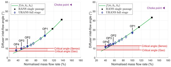
Figure 11.
Estimation of the stability limit from single passage RANS calculations (left: CMP-1/right: CMP-2).
This modelling associated with the prediction of the value given by the models of the literature provides an estimation of the last stable mass flow rate. Even if the value mainly depends on the radius and width ratios, other quantities can be taken into account by some models as the inlet Mach number or the difference of main flow velocities at the hub and shroud. Ljevar [39] plots the critical angle as a function of the radius ratio for the fixed width ratio. Those are slightly different from the ones of CMP-1 and CMP-2. Gao et al. [47] investigated the effect of diffuser width ratio on the critical angle for fixed radius ratios while Senoo and Kinoshita [43] provided an inlet Mach number and width ratio dependency for some fixed radius ratio. A critical zone rather than a unique value is then defined using the different models of the literature since none seems to have a more established validity. It appears that critical values from Senoo’s model are pessimist regarding estimations from Gao’s model that match the values obtained by considering Ljevar’s works.
In any case, considering the critical angle from Senoo as the entry in the hazardous area seems to be a best practice for designers in the early design step. In that way, the mass flow rate corresponding to the entrance in the critical zone is underrated by 14% of the operating range by the extrapolation, compared to the full-annulus simulations, for CMP-1 and 9% for CMP-2. Such relative errors are acceptable as a first estimation of the stability limit, given the cost of the method.
5. Conclusions
A numerical investigation was performed on two centrifugal compressors with vaneless diffusers to identify and analyse the mechanisms leading to stall and surge. A focus on the impellers revealed that backflow vortex shedding was responsible for the stall of impeller inducers. However, the reorganisation of the stall pattern into an axisymmetric recirculation near the casing restabilises the impeller inlet by reducing the incidence angle in the healthy flow region. Then, the destabilisation of the vaneless diffusers was studied. During this step, characteristic flow structures of an unstable core flow in a wide diffuser were observed.
A first-order stability analysis was carried out to clarify the role of each phenomenon in the loss of stability of the studied compressors. It revealed that the impellers were stabilising the stages at the last stable operating point while the vaneless diffuser was the critical component. This configuration is the one generally reported in the literature when the rotor flow presents a recirculation. Thus, a stability criterion based on a critical flow angle at the diffuser inlet was identified.
Considering all these elements, a predictive methodology of the stability limit at low mass flow rates could be proposed. This method consists of obtaining a relation giving the diffuser flow angle as a function of the mass flow rate recalibrated from two single passage RANS simulations performed on high mass flow operating points. The intersection of this extrapolation law with the values of the critical angle obtained from models of the literature provides an estimation of the last stable mass flow.
Given the number of critical angle models in the literature, this method would be more accurate if each company were to develop its own surrogate models predicting the critical angle from their machines. In addition to the present study, this methodology has also proven to be effective at the lowest rotation rates of the CMP-1 and CMP-2 compressors. However, Cravero and Marsano [50] observed that the limiting component could be the volute for the highest rotation rates. This fact raises interrogations about the suitability of the proposed predictive methodology on these speed lines. However, the computational cost of the full-annulus unsteady simulations required to validate the stability limit prediction of the stability limit has not yet made it possible to provide an answer. Hence, it would be interesting to test, in the future, the present methodology on the highest rotation rates.
Author Contributions
Conceptualisation, X.F., N.B., Y.B., and S.C.; methodology, X.F., N.B., Y.B., V.C., S.C., and N.P.; validation, X.F., N.B., Y.B., V.C., S.C., and N.P.; formal analysis, X.F.; investigation, X.F.; data curation, X.F.; writing—original draft preparation, X.F.; writing—review and editing, X.F., N.B., Y.B., V.C., S.C., and N.P.; visualisation, X.F.; supervision, N.B., Y.B., V.C., S.C., and N.P.; project administration, N.B., Y.B., V.C., S.C., and N.P.; funding acquisition, N.B., Y.B., and S.C. All authors have read and agreed to the published version of the manuscript.
Funding
This research received no external funding.
Institutional Review Board Statement
Not applicable.
Informed Consent Statement
Not applicable.
Data Availability Statement
The data presented in this study are available upon request from the corresponding author.
Acknowledgments
The authors would like to express their thanks to Liebherr-Aerospace Toulouse S.A.S for supporting the present research program. This work was granted access to the HPC resources of IDRIS under the allocation 2024-A0152A06879 made by GENCI and was granted access to the HPC resources of CALMIP supercomputing centre under the allocation 2023-P18021.
Conflicts of Interest
Authors Viviane Ciais, Sandrine Cros, and Nicolas Poujol were employed by the company Liebherr-Aerospace Toulouse SAS. The remaining authors declare that the research was conducted in the absence of any commercial or financial relationships that could be construed as a potential conflict of interest.
Abbreviations
The following abbreviations are used in this manuscript:
| Nomenclature |
| h | Diffuser width (m) |
| k | Fitting parameter |
| Mass flow rate (kg/s) | |
| P | Pressure (Pa) |
| Pressure Side | |
| R | Radius (m) |
| S | Passage area (m2) |
| Suction Side | |
| t | Time (s) |
| U | Rotation speed (m/s) |
| V | Absolute velocity (m/s) |
| W | Relative velocity (m/s) |
| Backflow Vortex | |
| Blade Passing Frequency | |
| Leading Edge | |
| Operating Point number “i” | |
| Stability Parameter | |
| Splitter blade |
| Greek symbols |
| Absolute flow angle (deg) | |
| Relative flow angle (deg) | |
| Incidence angle (°) | |
| Time step (s) | |
| Circumferential position (°) | |
| Throttle parameter | |
| Pressure ratio | |
| Density (kg/m3) | |
| Rotation rate (rad/s) | |
| Vorticity (/s) |
| Subscripts and superscripts |
| C | Compressor |
| d | Diffuser |
| Inlet | |
| Outlet | |
| R | Rotor |
| s | Static quantity |
| S | Stator |
| Static-to-static | |
| Total-to-static | |
| Total-to-total | |
| (r, , x) | Cylindrical coordinates |
References
- Day, I. Stall, surge, and 75 years of research. J. Turbomach. 2016, 138, 011001. [Google Scholar] [CrossRef]
- Emmons, H.; Pearson, C.; Grant, H. Compressor surge and stall propagation. Trans. Am. Soc. Mech. Eng. 1955, 77, 455–467. [Google Scholar] [CrossRef]
- He, X.; Zheng, X. Flow instability evolution in high pressure ratio centrifugal compressor with vaned diffuser. Exp. Therm. Fluid Sci. 2018, 98, 719–730. [Google Scholar] [CrossRef]
- Zhang, L.; He, R.; Wang, S.; Zhang, Q. A review of rotating stall in vaneless diffuser of centrifugal compressor. J. Therm. Sci. 2020, 29, 323–342. [Google Scholar] [CrossRef]
- Jansen, W. Rotating Stall in a Radial Vaneless Diffuser. J. Basic Eng. 1964, 86, 750–758. [Google Scholar] [CrossRef]
- Guadagni, S.; Giachi, M.; Fusi, L.; Farina, A. Flow stability in a wide vaneless diffuser. Appl. Eng. Sci. 2020, 4, 100025. [Google Scholar] [CrossRef]
- Cordier, O. Similarity considerations in turbomachines. VDI Rep. 1955, 3, 955. [Google Scholar]
- Flete, X.; Binder, N.; Bousquet, Y.; Cros, S. Numerical Investigation of Rotating Instability Development in a Wide Tip Gap Centrifugal Compressor. Int. J. Turbomach. Propuls. Power 2023, 8, 25. [Google Scholar] [CrossRef]
- Menter, F.R. Two-equation eddy-viscosity turbulence models for engineering applications. AIAA J. 1994, 32, 1598–1605. [Google Scholar] [CrossRef]
- Durbin, P.A. On the k-ε stagnation point anomaly. Int. J. Heat Fluid Flow 1996, 17, 9–90. [Google Scholar] [CrossRef]
- Kulak, M.; Grapow, F.; Liśkiewicz, G. Numerical analysis of centrifugal compressor operating in near-surge conditions. J. Phys. Conf. Ser. 2018, 1101, 012017. [Google Scholar] [CrossRef]
- Greitzer, E.M. The stability of pumping systems the 1980 Freeman Scholar Lecture. J. Fluids Eng. 1981, 103, 193–242. [Google Scholar] [CrossRef]
- Pavesi, G.; Cavazzini, G.; Caignaert, G.; Bois, G.; Ardizzon, G.; Dazin, A. Experimental and numerical investigation of unforced unsteadiness in a vaneless radial diffuser. In Proceedings of the European Conference on Turbomachinery Fluid Dynamics and Thermodynamics, Istanbul, Turkey, 21–25 March 2011. [Google Scholar]
- Fan, M.; Dazin, A.; Bois, G.; Romanò, F. Effect of inlet leakage flow on the instability in a radial vaneless diffuser. Phys. Fluids 2023, 35, 014105. [Google Scholar] [CrossRef]
- Bousquet, Y.; Binder, N.; Dufour, G.; Carbonneau, X.; Roumeas, M.; Trébinjac, I. Numerical simulation of stall inception mechanisms in a centrifugal compressor with vaned diffuser. J. Turbomach. 2016, 138, 121005. [Google Scholar] [CrossRef]
- Inoue, M.; Kuroumaru, M. Structure of Tip Clearance Flow in an Isolated Axial Compressor Rotor. J. Turbomach. 1989, 111, 250–256. [Google Scholar] [CrossRef]
- Inoue, M.; Kuroumaru, M.; Iwamoto, T.; Ando, Y. Detection of a Rotating Stall Precursor in Isolated Axial Flow Compressor Rotors. J. Turbomach. 1991, 113, 281–287. [Google Scholar] [CrossRef]
- Inoue, M.; Kuroumaru, M.; Tanino, T.; Furukawa, M. Propagation of Multiple Short-Length-Scale Stall Cells in an Axial Compressor Rotor. J. Turbomach. 1999, 122, 45–54. [Google Scholar] [CrossRef]
- Inoue, M.; Kuroumaru, M.; Tanino, T.; Yoshida, S.; Furukawa, M. Comparative Studies on Short and Long Length-Scale Stall Cell Propagating in an Axial Compressor Rotor. J. Turbomach. 2000, 123, 24–30. [Google Scholar] [CrossRef]
- Mathioudakis, K.; Breugelmans, F.A.E. Development of Small Rotating Stall in a Single Stage Axial Compressor. In Proceedings of the Volume 1: Aircraft Engine; Marine; Turbomachinery; Microturbines and Small Turbomachinery. American Society of Mechanical Engineers, Houston, TX, USA, 18–21 March 1985; p. V001T03A064. [Google Scholar] [CrossRef]
- Mailach, R.; Lehmann, I.; Vogeler, K. Rotating Instabilities in an Axial Compressor Originating From the Fluctuating Blade Tip Vortex. J. Turbomach. 2000, 123, 453–460. [Google Scholar] [CrossRef]
- März, J.; Hah, C.; Neise, W. An Experimental and Numerical Investigation into the Mechanisms of Rotating Instability. J. Turbomach. 2002, 124, 367–374. [Google Scholar] [CrossRef]
- Cao, T.; Kanzaka, T.; Xu, L.; Brandvik, T. Tip Leakage Flow Instability in a Centrifugal Compressor. J. Eng. Gas Turbines Power 2021, 143. [Google Scholar] [CrossRef]
- Chen, H.; Li, Y.; Tan, D.; Katz, J. Visualizations of flow structures in the rotor passage of an axial compressor at the onset of stall. J. Turbomach. 2017, 139, 041008. [Google Scholar] [CrossRef]
- Jeong, J.; Hussain, F. On the identification of a vortex. J. Fluid Mech. 1995, 285, 69–94. [Google Scholar] [CrossRef]
- Pullan, G.; Young, A.M.; Day, I.J.; Greitzer, E.M.; Spakovszky, Z.S. Origins and Structure of Spike-Type Rotating Stall. J. Turbomach. 2015, 137, 051007. [Google Scholar] [CrossRef]
- Harley, P.; Spence, S.; Filsinger, D.; Dietrich, M.; Early, J. Meanline modeling of inlet recirculation in automotive turbocharger centrifugal compressors. J. Turbomach. 2015, 137, 011007. [Google Scholar] [CrossRef]
- Ljevar, S.; De Lange, H.; Van Steenhoven, A. Two-dimensional rotating stall analysis in a wide vaneless diffuser. Int. J. Rotating Mach. 2006, 2006, 1–11. [Google Scholar] [CrossRef]
- Abdelhamid, A.N.; Bertrand, J. Distinctions Between Two Types of Self Excited Gas Oscillations in Vaneless Radial Diffusers. In Proceedings of the Turbo Expo: Power for Land, Sea, and Air. American Society of Mechanical Engineers Digital Collection, Montreal, QC, Canada, 15–19 June 2015. [Google Scholar] [CrossRef]
- Fan, M.; Dazin, A.; Bois, G.; Romanò, F. Instabilities in a turbulent swirling source flow between parallel rings. Phys. Fluids 2023, 35, 101701. [Google Scholar] [CrossRef]
- Fan, M.; Dazin, A.; Bois, G.; Romanò, F. Effect of radius ratio on the instabilities in a vaneless diffuser. Eur. J. Mech. B/Fluids 2024, 104, 1–7. [Google Scholar] [CrossRef]
- Fujisawa, N.; Tajima, K.; Miida, H.; Ohta, Y. Generation Mechanism of Diffuser Stall in a Centrifugal Compressor with Vaneless Diffuser. J. Glob. Power Propuls. Soc. 2020, 4, 190–201. [Google Scholar] [CrossRef]
- Bakket, E.; Kreider, J.; Kreith, F. Turbulent source flow between parallel stationary and co-rotating disks. J. Fluid Mech. 1973, 58, 209–231. [Google Scholar] [CrossRef]
- Raal, J. Radial source flow between parallel disks. J. Fluid Mech. 1978, 85, 401–416. [Google Scholar] [CrossRef]
- Weiss, J.; Mohammed-Taifour, A.; Schwaab, Q. Unsteady behavior of a pressure-induced turbulent separation bubble. AIAA J. 2015, 53, 2634–2645. [Google Scholar] [CrossRef]
- Agari, Y.; Yamao, Y.; Fujisawa, N.; Ohta, Y. Behavior of Vaneless Diffuser Stall in a Centrifugal Compressor. J. Therm. Sci. 2022, 31, 3–12. [Google Scholar] [CrossRef]
- Grapow, F.; Olasek, K.; Liśkiewicz, G.; Magiera, R.; Kryłłowicz, W. Experimental study of vaneless diffuser rotating stall development and cell-merging phenomena. J. Turbomach. 2021, 143, 051008. [Google Scholar] [CrossRef]
- Dean, R.C. The fluid dynamic design of advanced centrifugal compressors. In Advanced Radial Compressors; Von Karman Institute for Fluid Dynamics: Sint Heinesus-Rode, Belgium, 1974. [Google Scholar]
- Ljevar, S. Rotating Stall in Wide Vaneless Diffusers. Ph.D. Thesis, Technische Universiteit Eindhoven, Eindhoven, The Netherland, 2007. ISBN 9789038626796. [Google Scholar]
- Haeckel, T.; Paul, D.; Leichtfuß, S.; Schiffer, H.P.; Eißler, W. Determination of a Numerical Surge Limit by Means of an Enhanced Greitzer Compressor Model. Int. J. Turbomach. Propuls. Power 2023, 8, 48. [Google Scholar] [CrossRef]
- Greitzer, E.M. Surge and Rotating Stall in Axial Flow Compressors—Part I: Theoretical Compression System Model. J. Eng. Power 1976, 98, 190–198. [Google Scholar] [CrossRef]
- Tucci, F.; Delibra, G.; Tieghi, L.; Corsini, A.; Lavagnoli, S. Unsupervised learning for high-fidelity compression of large experimental dataset: An application on HPT blade tip contouring. In Proceedings of the European Conference on Turbomachinery Fluid Dynamics and Thermodynamics, Budapest, Hungary, 24–28 April 2023. [Google Scholar]
- Senoo, Y.; Kinoshita, Y. Influence of Inlet Flow Conditions and Geometries of Centrifugal Vaneless Diffusers on Critical Flow Angle for Reverse Flow. J. Fluids Eng. 1977, 99, 98–102. [Google Scholar] [CrossRef]
- Senoo, Y.; Kinoshita, Y.; Ishida, M. Asymmetric Flow in Vaneless Diffusers of Centrifugal Blowers. J. Fluids Eng. 1977, 99, 104–111. [Google Scholar] [CrossRef]
- Senoo, Y.; Kinoshita, Y. Limits of Rotating Stall and Stall in Vaneless Diffuser of Centrifugal Compressors. In Proceedings of the Turbo Expo: Power for Land, Sea, and Air. American Society of Mechanical Engineers Digital Collection, Charlotte, NC, USA, 26–30 June 1978. [Google Scholar] [CrossRef]
- Abdelhamid, A.N. Analysis of rotating stall in vaneless diffusers of centrifugal compressors. In Proceedings of the Turbo Expo: Power for Land, Sea, and Air. American Society of Mechanical Engineers, New Orleans, LA, USA, 10–13 March 1980; Volume 79665, p. V01BT02A089. [Google Scholar] [CrossRef]
- Gao, C.; Chuangang, G.; Wang, T.; Yang, B. Analysis of Geometries’ Effects on Rotating Stall in Vaneless Diffuser with Wavelet Neural Networks. Int. J. Rotat. Mach. 2008, 2007, 76476. [Google Scholar] [CrossRef]
- Zheng, X.; Jin, L.; Tamaki, H. Influence of volute-induced distortion on the performance of a high-pressure-ratio centrifugal compressor with a vaneless diffuser for turbocharger applications. Proc. Inst. Mech. Eng. Part J. Power Energy 2014, 228, 440–450. [Google Scholar] [CrossRef]
- Zhang, H.; Yang, C.; Shi, X.; Yang, C.; Chen, J. Two stall stages in a centrifugal compressor with a vaneless diffuser. Aerosp. Sci. Technol. 2021, 110, 106496. [Google Scholar] [CrossRef]
- Cravero, C.; Marsano, D. Criteria for the Stability Limit Prediction of High Speed Centrifugal Compressors With Vaneless Diffuser: Part II — The development of prediction criteria. In Proceedings of the Turbo Expo: Power for Land, Sea, and Air. American Society of Mechanical Engineers, Online, 21–25 September 2020; Volume 84102, p. V02ET39A013. [Google Scholar] [CrossRef]
Disclaimer/Publisher’s Note: The statements, opinions and data contained in all publications are solely those of the individual author(s) and contributor(s) and not of MDPI and/or the editor(s). MDPI and/or the editor(s) disclaim responsibility for any injury to people or property resulting from any ideas, methods, instructions or products referred to in the content. |
© 2024 by the authors. Licensee MDPI, Basel, Switzerland. This article is an open access article distributed under the terms and conditions of the Creative Commons Attribution (CC BY-NC-ND) license (https://creativecommons.org/licenses/by-nc-nd/4.0/).