Article

Prescribed Performance Rotating Formation Control of Multi-Spacecraft Systems with Uncertainties

1
School of Aeronautics and Astronautics, University of Electronic Science and Technology of China, Chengdu 611731, China
2
Aircraft Swarm Intelligent Sensing and Cooperative Control Key Laboratory of Sichuan Province, Chengdu 611731, China
3
National Innovation Institute of Defense Technology, Chinese Academy of Military Science, Beijing 100071, China
*
Author to whom correspondence should be addressed.
Drones 2022, 6(11), 348; https://doi.org/10.3390/drones6110348
Submission received: 11 October 2022 / Revised: 3 November 2022 / Accepted: 5 November 2022 / Published: 9 November 2022
(This article belongs to the Special Issue Multi-UAVs Control)

Abstract

:
This paper investigates the problem of rotating formation control for multi-spacecraft systems with prescribed performance in the presence of model uncertainties. Firstly, The spacecraft dynamics containing unmodelled parts is described in a polar coordinate system, which is to solve the problem of the controllable angular velocity of rotating formation. Then, the prescribed performance control method is improved by developing new prescribed performance functions. Based on the improved prescribed performance control method, the distributed controller is designed for multi-spacecraft systems to achieve rotating formations with prescribed performance, i.e., the formations error converges to a predefined arbitrarily small residual set, with convergence time no less than a prespecified value. And an RBF neural network is used to fit the unmodelled components of the spacecraft dynamics. Compared with the existing works of literature, this paper not only solves the robust prescribed performance rotating formation control of multi-spacecraft system, but also acheives rotating formation with adjustable angular velocity. Finally, the Lyapunov approach is employed for convergence analysis, and simulation results are provided to illustrate the effectiveness of the theoretical results.

1. Introduction

With the advancement of technology, the international community pays more and more attention to space development, consequently, the cluster of small satellites are closely followed [1,2,3]. For example, in 2016, NASA plans to launch a cluster of small satellites into orbit around the Earth in order to conduct more in-depth studies of the Earth’s climate and weather patterns (see Figure 1), the program known as “Time-Resolved Observations of Precipitation structure and storm Intensity with a Constellation of Smallsats” (TROPICS) [4]. To this day, the project is being slowly progressed. One of the key technologies for the cluster of small satellites is rotating formation of multi-satellites, i.e, Multiple following satellites in a formation configuration rotating around the leader satellite under the influence of gravity. It is used in a wide range of tasks such as surveillance, exploration, communication, combat, etc. However, as space mission requirements became more complex, electronics and communications technologies became more advanced, and professionals were placing higher demands on the quality of rotating formation, specifically its steady-state error, overshoot, and convergence speed, as well as its robustness. Those are both essential to the task’s success.
The rotating formation problem [5] refers to multi-spacecraft systems in a formation configuration rotating around the center of a circle under the action of an actuator. There are already some research results. Lin and Jia [5] defined the concepts of rotating consensus and rotating formation in a complex coordinate system using a second-order integrator as a study firstly, and designed a control protocol to implement rotating formation motion of multi-agent systems using kinematic knowledge of circular motion. And the results were extended to three dimensions in [6]. The aforementioned rotating formation controller [5,6] was based on undirected network topology, especially, the rotating formation motion under directed network topology was studied in [7]. With mixed uncertainties and communication delay between agents, a distributed rotating formation control scheme was presented for multi-spacecraft systems based on H control theory in [8]. Further, the problem of rotating formation with nonuniform delays was investigated in [9,10]. Founded on [7], article [11] investigated the rotating consensus of multi-spacecraft systems with signed directed graphs. article [12] addressed the rotating consensus of multi-agent systems with restricted communication, and article [13] studied rotating encirclement formations of second-order multi-agent systems with communication noises.
The results of the survey indicate the outstanding contribution of scholars on rotating formations in terms of communication topology and time delay, while the quality of the rotating formation is equally important, it affects the accuracy of satellites operations such as surveillance [14,15,16], communications [17,18], combat [19,20], etc. Literature [21] was concerned with the Control problem of a single-link flexible-joint robotic manipulator with dynamic uncertainties, considering the problem of pre-defined steady-state error and overshoot of the control system. Article [22] investigated the multi-agent formation problem with pre-defined steady-state error and overshoot. Formation of underwater unmanned aerial vehicles with pre-determined steady-state error and overshoot was investigated in [23]. And paper [24] studied formation control problem of underactuated surface vessels (USVs) with prescribed performance. There have also been many studies [25,26,27] in preset the steady-state error and overshoot of control systems, but these are few considered in rotating formations problems.
In addition, robustness is also an indicator of the quality of the rotating formation. The literature [8] first considers the problem of robustness of multi-agent consensus, which takes into account the effect of external disturbances. But there are still many problems need to be solved, such as the model uncertainties of nonlinear systems. Therefore, there is an urgent requirement to study control schemes that can improve the quality of rotating formations.
In summary, the problem of prescribed performance and uncertainties from unmodelled parts in each spacecraft’s dynamics in leader-following rotating formations are concerned in this paper. Prescribed performance control methods are used to ensure that the rotating formation control system meets the preset overshoot, steady-state error and convergence time. RBF neural networks are used to approximate uncertainties. The main contributions of this article are as follows:
(1) This paper deals with the prescribed performance robust rotating formation problem of multi-spacecraft systems with controllable angular velocity. To realize rotating formation motion with controlled angular velocity, spacecraft dynamics in a polar coordinate system including unmodelled parts is established. The dynamics contain the angular velocity state of the spacecraft. Compared with the existing works of [5,6,7,8] where the angular velocity is assumed to be a fixed value “1”, the formation in this paper can achieve any specified angular velocity rotating.
(2) A prescribed performance rotating formation controller is designed for the uncertain multi-spacecraft system, which can not only comply with the preset overshoot and steady-state error metrics of the closed-loop error system but also make the convergence time less than the preset value. By modifying the exponential function to a power-of-two function, a novel prescribed performance function is developed, which not only decreases computational complexity but also can provide the preset time metric. Compared with the works of [22,24,25,28,29,30] which can only guarantee control system stability. The proposed prescribed performance function-based controller in this paper is constructed to ensure various performance metrics for the rotating formation of the multi-spacecraft system.
(3) The neural networks-based approximator is constructed to estimate the lumped nonlinear model uncertainties of spacecraft. Meanwhile, the adaptive laws of neural network parameters are updated online. To this end, the robustness of the closed-loop error system is effectively enhanced. Compared with the works of [5,6,7,8,9,12] which only achieve the rotating formation of linear normal systems.
The rest of this paper is organized as follows: Section 2 introduces some preliminaries and presents the dynamics model of the spacecraft in the polar coordinate system. In Section 3, the main results of distributed rotating formation control based on the prescribed performance control method and RBF neural networks are proposed. In Section 4, simulation examples are designed to verify the effectiveness of the controller. Finally, Section 5 concludes the whole paper and discusses the future research work.

2. Preliminaries and Dynamics Model

In this section, some preliminary knowledges of graph theory, coordinate frame, and RBF neural networks are introduced. Then, the spacecraft dynamics model in the polar coordinate system is given.

2.1. Preliminaries

2.1.1. Graph Theory

Let G ( V , E ) be a undirected graph with n nodes, where V = { v 1 , , v n } is the set of nodes, E = V × V is the set of edges, and A = [ a i j ] R n × n , a i j 0 is a adjacency matrix. The node indexes belong to a finite index set I = { 1 , , n } . An edge of G is represented as e i j = { v i , v j } . If e i j E , a i j > 0 , else a i j = 0 . The set of neighbors of node v i is denoted by N i = { v j | ( v i , v j ) E } . The Laplacian matrix of the undirected graph is L = D A R n × n , where D = diag ( D 1 , , D n ) is a diagonal matrix, and D i = j N i a i j . If there exists a path between any two nodes, the undirected G is connected. And the corresponding Laplacian matrix L of graph G is semi-definite [31].
Assumption 1. 
Assuming that there are n spacecraft in multi-spacecraft systems and that the communication topology of the system is connected in this paper.

2.1.2. Coordinate Frame

For the purpose of the following analysis, two coordinate systems is defined:
Inertial coordinate system o l x l y l : Multi-spacecraft systems rotation center o l is chosen as the origin of the coordinate system. The x-axis( o l x l ) points in a fixed direction and the direction does not change with time. the y-axis( o l y l ) is perpendicular to the x-axis and satisfies the right-hand rule with x-axis.
Polar coordinate system o e x e y e : The spacecraft center of mass o e is chosen as the origin of the coordinate system. o e x e points from the origin of the inertial coordinate system to the origin of the polar coordinate system. o e y e and o e x e form a right-handed coordinate system. The inertial coordinate system is stationary, but the polar coordinate system is bound to the spacecraft, and moves with the spacecraft all the time, like the body coordinate system of a drone.

2.1.3. RBF Neural Network

The RBF neural networks are widely used to approximate uncertainties [32,33,34,35]. As indicated in [36], any continuous function f ( x ) : R R can be approximated by an RBF neural network over a compact set Ω x as
f ( x ) = W T φ ( x ) + δ ( x ) x Ω x .
where W R s represents the neural networks weight, δ ( x ) R denotes the fitting error, | δ ( x ) | can become arbitrarily small as the number of basis functions increases [35], φ ( x ) R s indicates the basic function vector.

2.1.4. Notions

The following notions will be used throughout this paper. The variable subscripts l , e represent the projection of the vector in the inertial or polar coordinate system, respectively, unless otherwise specified. Let R , R n and R n × n be the real number set, n-tuple real vector space and n × m real matrix space. is the 2-norm of a vector or a matrix. I n is an n × n identity matrix [37,38]. The diagonal matrix is denoted as diag ( ) . ⊗ means the Kronecker product, | | is the absolute value of a real number.
The concept of practical finit-time stable is defined in the following:
Definition 1 
(Practical Finit-time Stable [39]). Consider the nonlinear system x ˙ = f ( x ( t ) ) , x ( 0 ) = x 0 , where f : L R n is continuous on an open neighbourhood of the origin. The equilibrium x = 0 of nonlinear system is practical finit-time stable if for all x ( t 0 ) = x 0 , there exists ϵ > 0 and a time T ( ϵ , x 0 ) < to make x ( t ) < ϵ , for t t 0 + T .
Lemma 1 
([40]). For η 1 R and δ t > 0 , the following inequality always holds:
0 | η 1 | η 1 t a n h ( η 1 δ t ) 0.2785 δ t .
Lemma 2. 
For e R 2 and e 0 2 , 0 2 = [ 0 , 0 ] T , there exists h R 2 such that
e T h = 1 .
Proof. 
Let e = [ e 1 , e 2 ] T , h = [ h 1 , h 2 ] T .
(1) If e 1 = 0 , e 2 0 : Since e 1 h 1 + e 2 h 2 = 1 , we have h 2 = 1 e 2 and h 1 can take any value.
(2) If e 1 0 , e 2 = 0 : Since e 1 h 1 + e 2 h 2 = 1 , we have h 1 = 1 e 1 and h 2 can take any value.
(3) If e 1 0 , e 2 0 : We take the value of h 2 to be 0. Since e 1 h 1 + e 2 h 2 = 1 , we have h 1 = 1 e 1 .
Thus, Lemma 2 is proved. □

2.2. Dynamics Model

In many cases the formation spacecraft will operate in the same plane. Therefore, to simplify the analysis, this paper considers spacecraft dynamics in multi-spacecraft systems modeling in the two-dimensional plane, and each spacecraft is represented by a mass point, then the dynamics model of the ith spacecraft in the polar coordinate system can be described as:
r ˙ i = v i θ ˙ i = w i v ˙ i = u e i v + r i w i 2 + d e i v ( r i , θ i , v i , w i , t ) r i w ˙ i = u e i w 2 v i w i + d e i w ( r i , θ i , v i , w i , t ) , i I .
The index set of an n-spacecraft system is defined as I = { 1 , , n } . r i R + , v i R denote the distance of the spacecraft i from the origin of the inertial system to the spacecraft i and its derivative, respectively. θ i , w i R denotes the angle between the polar coordinate system x-axis of the spacecraft i and the inertial system x-axis and angular velocity, respectively. u e i v , u e i w R denotes the projection of the control input of the spacecraft i on the x-axis and y-axis of the polar coordinate system, respectively. d e i v ( r i , θ i , v i , w i , t ) , d e i w ( r i , θ i , v i , w i , t ) denote unmodelled parts of the spacecraft i.
Remark 1. 
The states r i , θ i of the ith spacecraft in (2) indicates the polar axis and polar angle. The polar axis refers to the distance from the current position of the spacecraft to the center of rotation, which is the origin of the inertial system. And the polar angle refers to the angle between the line connecting the position of the spacecraft and the center of rotation and the x-axis of the inertial coordinate system. When the rotating formation is realized, although the positions of the spacecraft are changing at all times, their polar axes are fixed, and since the formation configuration is generally fixed, the polar angle difference between any spacecraft is also fixed, which transforms the rotating formation problem into the traditional consensus formation problem. Besides, the angular velocity w i is included in the (2), thus rotating formation with controllable angular velocity will be achieved when the states in (2) can track the desired information under the action of the designed controller. In addition, r i less than or equal to 0 has no physical meaning. So the constraint r i > 0 should be noted when designing the controller.
Remark 2. 
The dynamics of the spacecraft in this study are based on the Newtonian dynamics of a mass in a polar coordinate system. In order to study spacecraft rotating formation control problems, many researchers simplified the spacecraft dynamics to a second-order integrator [5,6,7,8,9], however two questions were highlighted. The inability to create controllers that produce rotating formation with controllable angular velocity is the first issue. Consequently, the simplified spacecraft dynamics model in the inertial system is transformed into the polar coordinate system in this article. The oversimplified spacecraft dynamics is the second issue. The Newtonian dynamics of a mass in the polar coordinate system cannot be easily adapted to the spacecraft dynamics model since the latter is nonlinear. And a nonlinear factor that is unknown and challenging to analyze will be present in the spacecraft dynamics when it is immediately transformed to the polar coordinate system. Consequently, this article extends the mass point dynamics under the polar coordinate system to include an uncertainties element d e i v ( r i , θ i , v i , w i , t ) , d e i w ( r i , θ i , v i , w i , t ) in order to get closer to the actual spacecraft dynamics.
Define that p i = [ r i , θ i ] T , q i = [ v i , w i ] T , then (2) can be simplified as the following compact form:
p ˙ i = q i , B i q ˙ i = u i + f i + d i .
where
B i = 1 0 0 r i , f i = r i w i 2 2 v i w i , u i = u e i v u e i w , d i = d e i v ( r i , θ i , v i , w i , t ) d e i w ( r i , θ i , v i , w i , t ) .
Since r i > 0 , B i is positive definite.

2.3. Problem Description

There are n spacecraft and a leader, some of the spacecraft can receive information from the leader’s states, but most of them just know the relative desired state between themselves and their neighbors. Our main objective is to design a distributed controller to make multi-spacecraft systems form a certain configuration to do the circular motion with desired angular velocity in the presence of uncertainties, and the rotating formation control system satisfies various preset performance indicators, such as overshoot, steady state error, convergence time, etc. Before giving the main results, we need to make the following definitions.
Definition 2. 
Multi-spacecraft systems is said to achieve rotating formation with prescribed performance if the value of T , Δ 1 , Δ 2 is predetermined by the user and the states of all the spacecraft satisfy that
lim t T | r i r j r i j d | Δ 1 , lim t T | θ i θ j θ i j d | Δ 2 , lim t | v i | Δ 3 , lim t | w i w j | Δ 4 .
where r i j d , θ i j d are the deviations of desired relative state between spacecraft i and spacecraft j. r i d denotes the desired length of spacecraft i, then r i j d = r i d r j d , we have r i j d = r j i d . Similarly, the desired angle of the spacecraft i is θ i d , then θ i j d = θ i d θ j d . w i d denotes the desired angular velocity of the spacecraft i, and T represents the preset convergence time, and Δ 1 , Δ 2 represent the preset metrics of steady-state error, Δ 3 , Δ 4 indicates very small positive numbers.
Remark 3. 
The physical meaning of (4) is that the difference between any two spacecraft’s polar axes r i r j and their polar angles θ i θ j , as time tends to a preset value T, tends to the desired difference r i j d and θ i j d , and the error between the actual difference and desired difference | r i r j r i j d | , | θ i θ j θ i j d | is smaller than the preset value Δ 1 , Δ 2 . Additionally, the derivative of the polar axes v i and the difference of their angular velocities w i w j , when time approaches to infinity, tends to a neighborhood containing 0. Only the performance of the errors about the polar axis and the polar angle are preset in Definition 2 because for actual systems, we commonly expect the spacecraft to reach a given position in a preset time T. If the performance of the angular velocity was further prescribed in the Definition 2, it would be more challenging to build the controller.
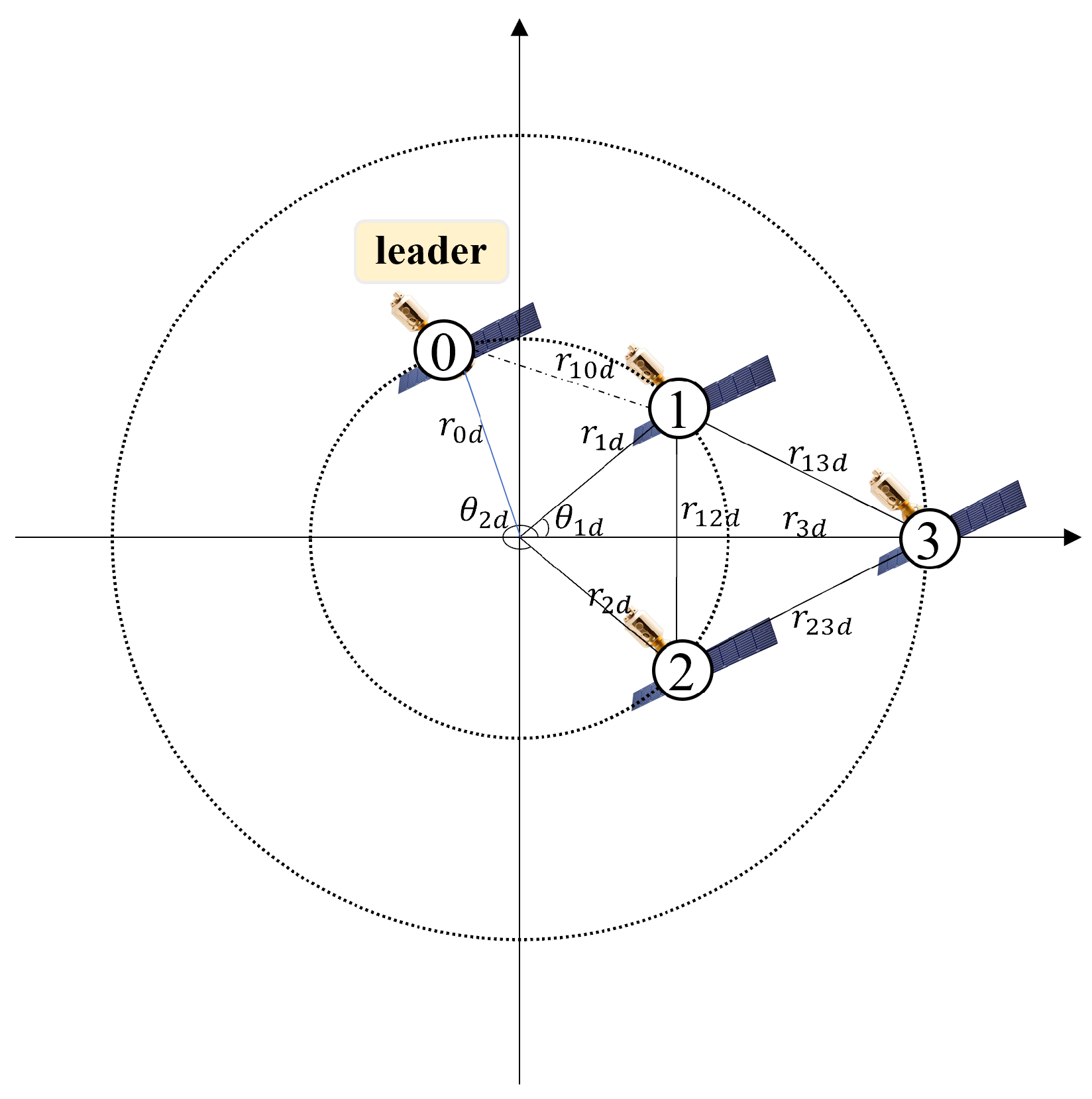
The conditions in (4) mean that multi-spacecraft systems will achieve rotating formation in a preset time, and the formation error is less than the preset value finally. In contrast to the literature [5], the definition in this paper does not require exponential and complex calculations. As shown in Figure 2, the three spacecraft and a leader have realized a rotating formation, and the interrelationship between the spacecraft can be visually represented.

3. Main Results

3.1. Controller Design

Since only certain spacecraft can obtain the leader’s states p 0 = [ r 0 , θ 0 ] and the majority of spacecraft only know the desired relative state between themselves and their neighbors, the rotating formation error is defined as follows:
e p i = c i ( p i p 0 p i 0 d ) + j = 1 n a i j ( p i p j p i j d ) , e q i = c i ( q i q 0 q i 0 d ) + j = 1 n a i j ( q i q j q i j d ) .
where c i indicates whether spacecraft i can receive the leader’s states, and if it can, c i = 1 , otherwise c i = 0 . p i j d = [ r i j d , θ i j d ] T , q i j d = p ˙ i j d . And assume the leader is moving along the desired path, the following dynamic equation is satisfied by the leader’s states:
r ˙ 0 = 0 , θ ˙ 0 = w 0 d , r 0 ( 0 ) = r 0 d , θ ˙ 0 ( 0 ) = 0 .
where w 0 d denotes desired rotating formation’s angular velocity, and r 0 d represents the desired radius of rotation.
As a convenience for the stability proof following, define desired state of spacecraft i as p i d = [ r i d , θ i d ] T and its derivative is q i d = p ˙ i d , then, there have p i j d = p i d p j d , q i j d = q i d q j d . Since the leader is now following the planned trajectory, i.e., p 0 = p 0 d , q 0 = q 0 d , there have p i d = p i 0 d + p 0 d = p i 0 d + p 0 and q i d = q i 0 d + q 0 d = q i 0 d + q 0 . Define that
e p = [ e p 1 T , , e p n T ] T , e q = [ e q 1 T , , e q n T ] T , p = [ p 1 T , , p n T ] T , q = [ q 1 T , , q n T ] T ,
p d = [ p 1 d T , , p n d T ] T , q d = [ q 1 d T , , q n d T ] T , C = diag ( c 1 , c n ) , H = ( C + L ) I 2 .
where I 2 R 2 × 2 denotes the unit matrix. Then
e p = H ( p p d ) , e q = H ( q q d ) .
According to Assumption 1, H is positive definite, so p p d , q q d will converge to 0 when e p , e q converges to 0, then the Equation (4) will hold, therefore the system will realize the rotating formation. But due to the problems of uncertainties, calculation accuracy, and actuator output accuracy, it is difficult for e p , e q to converge to 0 exactly, so if e p , e q can finally satisfy the preset metrics of steady-state error, it is also said that the system achieves the rotating formation.
To achieve the rotating formation motion with prescribed performance, according to the prescribed performance control theory [41], the inequality describing the performance of the rotating formation error is defined as:
v 1 i , m p t < e p i , m < v 2 i , m p t , m = 1 , 2 , v 1 i , m = r + 1 2 + sign e p i , m 0 r 1 2 R , v 2 i , m = r + 1 2 + sign e p i , m 0 1 r 2 R .
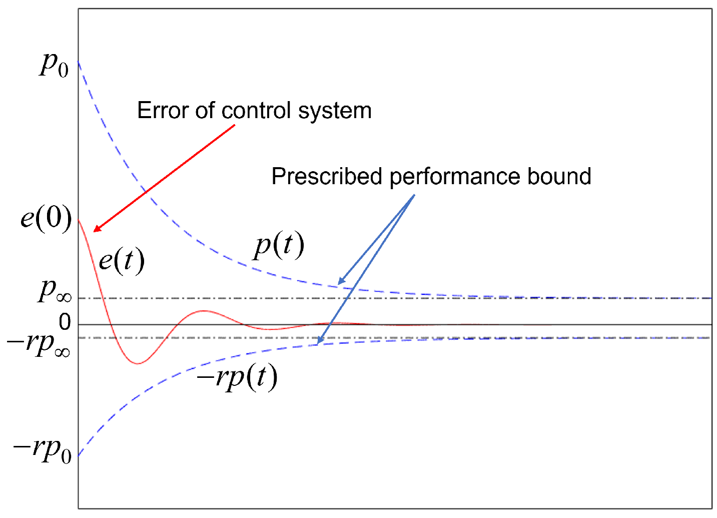
where e p i , m R denotes the mth element of the vector e p i and p ( t ) R denotes the performance function that constrains the transient-state convergence process and steady-state error of the control system, which is designed as p t = p 0 p e l t + p in [22,25,26,42,43,44]. r [ 0 , 1 ] is a constant that constrains the maximum overshoot of the error. p can constrain the steady-state error of the rotating formation error. And e l t can constrain the transient-state convergence process of the rotating formation error. sign x is the signum function, which described as:
sign x = 1 , x 0 1 , x < 0
The conditions in (8) can be graphically depicted by Figure 3. e 0 R is greater than 0, then v 1 i , m = r , v 2 i , m = 1 . If (8) is satisfied, e t will be contained within the function envelope consisting of p t and r p t over the entire time domain. Then the whole response process of e t will satisfy the user-set performance metrics such as overshoot, convergence speed, steady-state error, etc.
From the formula of p ( t ) in [22,25,26,42,43,44], we have p t p when t . Then only when t , there is e t < p . According to Definition 1, the control system is not finite time convergence. To solve this problem, a new prescribed performance function in this paper is described as:
p ( t ) = p 0 ( 1 t T ) 2 + p , t < T p , t T .
The performance function defined by (9) is p t p when t T , then when t T , there is e t < p , According to Definition 1, e ( t ) is the practical finit-time stable.
For the convenience of controller design, the constraint of the rotating formation error defined by (8) is transformed into an unconstrained form by an error transformation. The error transformation function is defined as:
e p i , m t = p t f ε p i , m .
Let Λ p i , m = e p i , m t p t R , then the inverse of f ε p i , m can be written as:
ε p i , m = f 1 e p i , m t p t = f 1 Λ p i , m .
f 1 ( · ) is taken to be in logarithmic functional form and is written as:
ε p i , m = ln v 2 i , m v 1 i , m + Λ p i , m v 1 i , m v 2 i , m Λ p i , m R , m = 1 , 2 .
Its definition domain is:
Θ : = v 1 i , m , v 2 i , m .
The equation in (12) shows that if ε p i , m is bounded, then Λ p i , m will satisfies:
v 1 i , m < Λ p i , m < v 2 i , m .
Consequently, e p i , m satisfies (8), and the problem is then transformed into designing the controller so that ε p i , m is bounded.
Then, we can obtain the derivative of (11) as:
ε ˙ p i , m = d ε p i , m d Λ p i , m d Λ p i , m d t = ζ p i , m e ˙ p i , m t + η e p i , m t .
where
0 η = p ˙ t p t < 2 T , 0 < ζ p i , m = v 1 i , m + v 2 i , m v 1 i , m + Λ p i , m v 2 i , m Λ p i , m 1 p t .
Define ε p i = ε p i , 1 , ε p i , 2 T as the transformed rotating formation error, the derivative of which is:
ε ˙ p i = ξ p i e ˙ p i + η e p i .
where ξ p i = diag ξ p i , 1 , ξ p i , 2 .
From Lemma 2, there exsits h i R 2 , we get e p i T h i = 1 when e p i 0 . For the purpose of controller design, the vector function is defined as:
g i = k ε ε p i + ξ p i ε p i + B i 1 d i q ˙ i d + η ε p i T ξ p i e p i h i .
Fitting g i using the RBF neural networks:
g i = W i T φ i + δ i , φ i = e e p i 1 s μ 2 2 e q i 1 s μ 2 2 ε p i 1 s μ 2 2 R s .
where μ is the center of the receptive field, and 1 s denotes s-dimensional 1-vector.
To achieve rotating formation, the controller of the spacecraft i is designed as:
u i = B i k ε ε p i + k q e q i + u t i f i , u t i = W ^ i T φ i tanh ( W ^ i T φ i e q i δ t ) , W ^ ˙ i = γ e q i φ i .
where k ε > 0 , k q > 1 2 , δ t > 0 , γ > 0 .
Remark 4. 
B i , f i in u i are used to linearize the spacecraft dynamics model. The nonlinear terms Containing the unmodelled parts are fitted using the RBF neural networks u t i . The consensus control term k ε ε p i + k q e q i is used to achieve the rotating formation motion with the prescribed performance and controllable angular velocity.
Since φ i 0 , then W ^ ˙ i 0 , and the initial value of the weight W ^ i in this paper is vector 0 s , thus, we have
W ^ i φ i 0 .

3.2. Stability Analysis

Theorem 1. 
Consider multi-spacecraft systems of n spacecraft with a connected communication topology. With the controller (19), the performance metric defined by (8) can be satisfied for all time, and multi-spacecraft systems will achieve rotating formation with prescribed performance according to Definition 2, i.e., the states of each spacecraft satisfy (4) with (21):
Δ 1 = 4 n p H 1 , Δ 2 = 4 n p H 1 , Δ 3 = H 1 0.557 n δ t + i = 1 n 1 2 δ i 2 k q 0.5 , Δ 4 = 2 H 1 0.557 n δ t + i = 1 n 1 2 δ i 2 k q 0.5 .
Proof: According to (3) and (7), we have
e ˙ p = e q , e ˙ q = H q ˙ q ˙ d = H B 1 f + u + d q ˙ d .
where
f = [ f 1 T , , f n T ] T , d = [ d 1 T , , d n T ] T , B = diag B 1 , , B n , u t = [ u t 1 T , , u t n T ] T , u = [ u 1 T , , u n T ] T = B k ε ε p + k q e q + u t f .
Define that ε p = [ ε p 1 T , , ε p n T ] T , then ε p = ξ p e q + η e p , where ξ p = diag ξ p 1 , , ξ p n . The Lyapunov function is written
V = 1 2 ε p T ε p + 1 2 e q T H 1 e q + 1 2 γ i = 1 n W ˜ i T W ˜ i
where W ˜ i = W i W ^ i , then we have
V ˙ = ε p T ε ˙ p + e q T B 1 f + u + d e q T q ˙ d 1 γ i = 1 n W ˜ i T W ^ ˙ i = ε p T ξ p e q + η e p e q T k ε ε p + k q e q + u t + e q T B 1 d e q T q ˙ d 1 γ i = 1 n W ˜ i T W ^ ˙ i = k q e q T e q + e q T k ε ε p + ξ p ε p + B 1 d q ˙ d e q T u t + η ε p T ξ p e p 1 γ i = 1 n W ˜ i T W ^ ˙ i = i = 1 n e q i T k ε ε p i + ξ p i ε p i + B i 1 d i q ˙ i d + i = 1 n η ε p i T ξ p i e p i 1 γ i = 1 n W ˜ i T W ^ ˙ i k q i = 1 n e q i T e q i i = 1 n e q i T u t i .
Substituting (1), (17) and (19) into (24), we have
V ˙ = 1 γ i = 1 n W ˜ i T W ^ ˙ i + i = 1 n e q i T k ε ε p i + ξ p i ε p i + B i 1 d i q ˙ i d + η ε p i T ξ p i e p i h i k q i = 1 n e q i 2 i = 1 n W ^ i T φ i e q i T tanh ( W ^ i T φ i e q i δ t ) = i = 1 n W ˜ i T φ i e q i T tanh ( W ˜ i T φ i e q i δ t ) 1 γ i = 1 n W ˜ i T W ^ ˙ i + i = 1 n e q i T g i k q i = 1 n e q i 2 .
Under Lemma 1 and (20), (25) is simplified as
V ˙ i = 1 n W ^ i T φ i j = 1 2 e q i , j + 0.2785 · 2 · n δ t + i = 1 n e q i g i 1 γ i = 1 n W ˜ i T W ^ ˙ i k q i = 1 n e q i 2 .
From Young-inequality and (18), (26) can be reduced to:
V ˙ i = 1 n W ^ i T φ i e q i + 0.2785 · 2 · n δ t + i = 1 n e q i W i T φ i + δ i i = 1 n W ˜ i T e q i φ i k q i = 1 n e q i 2 = i = 1 n W ˜ i T φ i e q i i = 1 n W ˜ i T e q i φ i + 0.2785 · 2 · n δ t + i = 1 n e q i δ i k q i = 1 n e q i 2 k q 1 2 i = 1 n e q i 2 + 0.2785 · 2 · n δ t + i = 1 n 1 2 δ i 2 .
If (28) holds,
k q 1 2 i = 1 n e q i 2 0.2785 · 2 · n δ t + i = 1 n 1 2 δ i 2 .
We may have V ˙ > 0 , then ε , e q will become unstable and increase with time, if e q i keeps increasing until (29) holds,
k q 1 2 i = 1 n e q i 2 > 0.2785 · 2 · n δ t + i = 1 n 1 2 δ i 2 .
Then V ˙ becomes negative definite and ε , e q will decrease with time until (28) holds. Therefore, as time tends to infinity, ε , e q will converge within the bounded region and the (30) holds ( k q > 1 2 ).
lim t i = 1 n ( ( v i v i d ) 2 + ( w i w i d ) 2 ) = lim t q q d lim t H 1 H q q d = lim t H 1 i = 1 n e q i 2 H 1 0.557 n δ t + i = 1 n 1 2 δ i 2 k q 0.5 .
Consequently,
lim t | v i v i d | H 1 0.557 n δ t + i = 1 n 1 2 δ i 2 k q 0.5 ,
lim t | w i w i d | H 1 0.557 n δ t + i = 1 n 1 2 δ i 2 k q 0.5 .
Since v i d = 0 , we have
lim t | v i | H 1 0.557 n δ t + i = 1 n 1 2 δ i 2 k q 0.5 ,
lim t | w i w j w i j d | lim t ( | w i w i d | + | w j w j d | ) 2 H 1 0.557 n δ t + i = 1 n 1 2 δ i 2 k q 0.5 .
Since ε converges to within the bounded region, then (8) holds, so we have lim t T e p i , m < p . And then lim t T e p < 2 n p , i.e., when the time t T , the rotating formation error e p converges to within the preset steady-state error region. Since e p = H p p d , then there must be:
lim t T i = 1 n ( ( r i r i d ) 2 + ( θ i θ i d ) 2 ) = lim t T p p d lim t T H 1 H p p d 2 n p H 1 .
Consequently,
lim t T | r i r i d | 2 n p H 1 ,
lim t T | θ i θ i d | 2 n p H 1 .
Then, we have
lim t T | r i r j r i j d | lim t T ( | r i r i d | + | r j r j d | ) 4 n p H 1 ,
lim t T | θ i θ j θ i j d | lim t T ( | θ i θ i d | + | θ j θ j d | ) 4 n p H 1 .
In summary, the following inequality holds:
lim t | v i | H 1 0.557 n δ t + i = 1 n 1 2 δ i 2 k q 0.5 , lim t | w i w j w i j d | 2 H 1 0.557 n δ t + i = 1 n 1 2 δ i 2 k q 0.5 , lim t T | r i r j r i j d | 4 n p H 1 , lim t T | θ i θ j θ i j d | 4 n p H 1 .
The relationship between 4 n p H 1 and p allows us to infer that 4 n p H 1 represents the steady-state error that has been prescribed. As a result, the multi-spacecraft system can accomplish rotating formations with prescribed performance.
The proof of Theorem 1 is complete.

4. Simulation Results

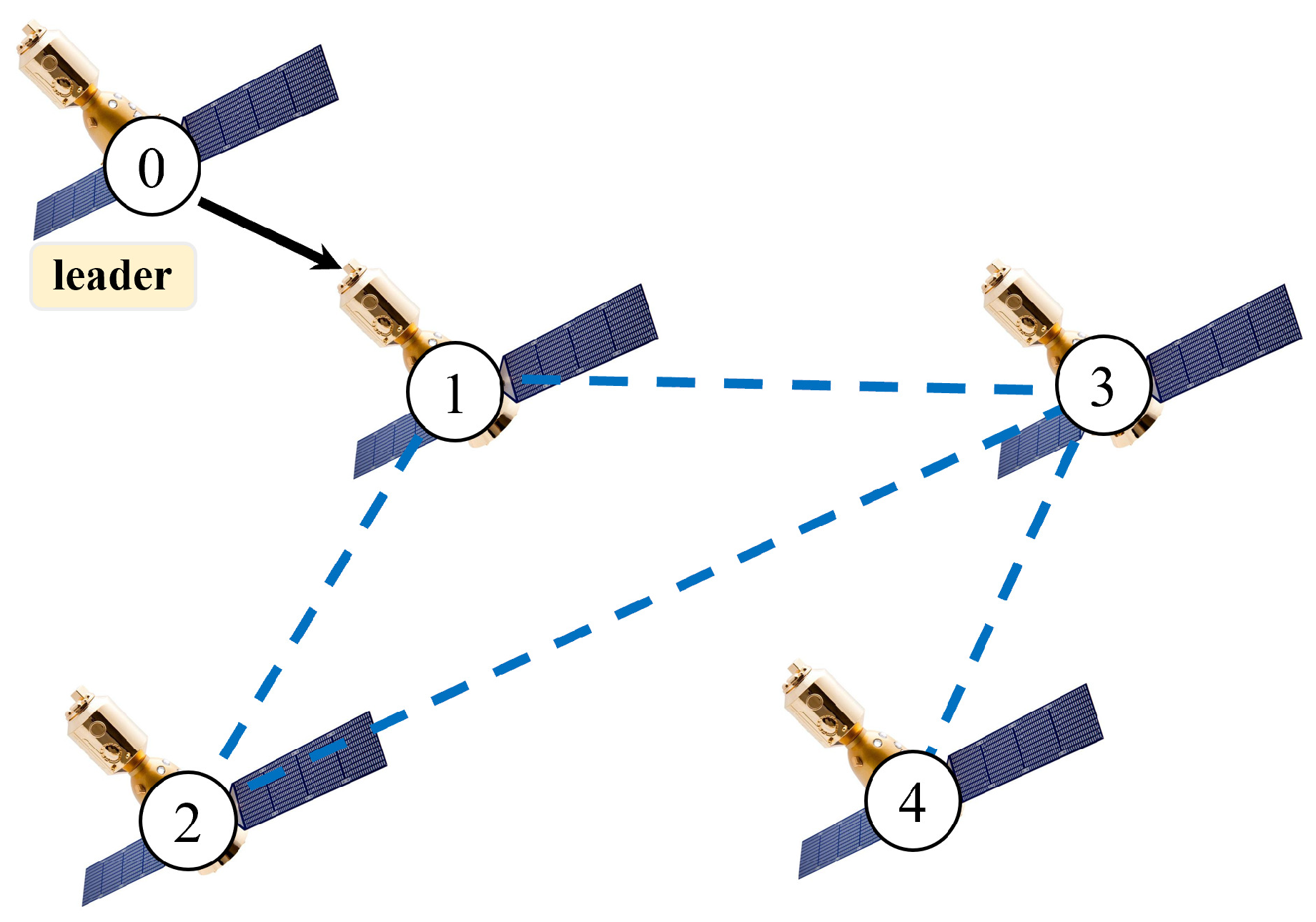
To illustrate the obtained theoretical results, numerical simulations will be given in this section. Figure 4 is a communication topology for multi-spacecraft systems that have four spacecraft and a leader, where only spacecraft 1 can receive the leader’s states.
The angular velocity of the leader is w 0 d = 0.4 , and radius of rotation of the leader is r 0 d = 7 . Four spacecraft form an equilateral triangle configuration for rotating formation around the center of the circle, then, the system’s parameter are shown in Table 1.
The desired difference p i j d and q i j d can be calculated from the desired states p i d and q i d .
The number of basis functions is s = 80 , select μ evenly from 5 , 5 , and Both all spacecraft’s parameters in the controller (19) are chosen as follows:
k ε = 8 , k q = 15 , δ t = 0.1 , γ = 0.5 .
The parameter in (8) is defined as r = 1 . The parameters of (9) are chosen as
p 0 = 20 , p = 1.5 × 10 4 , T = 10 .
According to (33), the control system’s maximum steady-state error should be less than 1.5 × 10 4 , its convergence time should be less than 10, and its maxmum overshot should be less than 100%.
Assuming that the unmodelled components of the spacecraft i is
d i = 0.2 i cos 0.1 t + 5 w i · sin 0.01 t + i π 5 + 0.05 i sin 0.3 t + 2.5 w i · cos 0.05 t + i π 6 + ( 5 + 0.1 i ) sin 0.02 t + v i · sin 0.1 t + 1.5 .
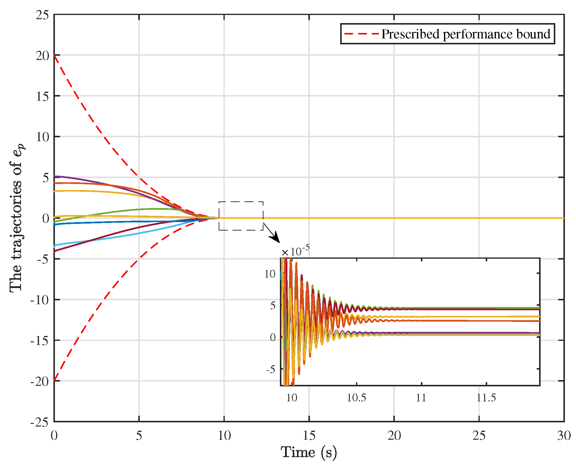
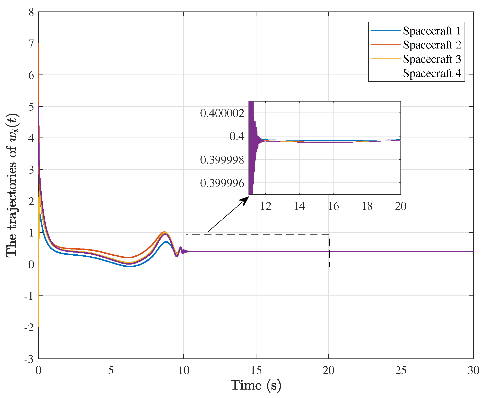
Simulation results are shown in Figure 5, Figure 6 and Figure 7. Figure 5 shows the trajectory of all spacecraft in 30 s, from which it is clear that multi-spacecraft systems eventually forms desired configuration to do circular motion around the origin. Figure 6 shows the time response curves of the rotating formation error e p i for all the spacecraft. The response process of this error reflects various performances of the system such as steady-error and convergence time of the formation control system, the convergence time and steady-error of rotating formation error are set in this paper at (33), and it can be seen from the Figure 6 that the system can achieve the rotating formation motion within 10 seconds and the steady-error of the rotating formation is less than 10 4 , which fully satisfies the performance preset above, and there is no overshoot in the response process of the error. Figure 7 shows the angular velocity response curves of all spacecraft, from which it can be seen that the final convergence error of angular velocity is less than 10 5 . For perspective, the performance metrics of the rotating formations of the multi-spacecraft system are summarized in Table 2. Therefore, the controller designed in this paper not only resists uncertainties but also can meet various preset performance indicators, and finally achieve rotating formation with high precision and controlled angular velocity in preset time.

5. Conclusions

This paper studied the problem of rotating formation of multi-spacecraft systems with prescribed performance and controllable angular velocity in the presence of model uncertainties. The spacecraft dynamics is presented in a polar coordinate system for the realization of rotating formation with controlled angular velocity. The prescribed performance control method is used to solve the problem of rotating formation with prescribed performance, i.e, the rotating formation error converges to a preset region in a preset time and the transient and steady-state response curves meet preset performance. And an RBF neural network is used to approximate model uncertainties. Finally, simulation results demonstrate the effectiveness of the controller.
In future work, we will consider the problem of controlled angular velocity rotating encirclement control, such as, In the presence of non-matching interference, the controller is designed to make multi-spacecraft systems form a configuration to rotate around a moving target for surveillance or attack.

Author Contributions

Y.L., W.L., L.C. and M.S. conceived the conceptualization and control scheme. Y.L. and W.L. completed the implementation of the scheme and the writing of the paper, and supported the writing review and editing. B.L. completed some preliminary simulations, and did preliminary research and summary. K.Q. provides theoretical guidance and suggestions for revision of the paper. All authors have read and agreed to the published version of the manuscript.

Funding

This work is supported by the Science & Technology Department of Sichuan Province under Grant No. 2022JDR0107, 2020YJ0044, 2021YFG0131, the Fundamental Research Funds for the Central Universities under Grant No. ZYGX2020J020 and the National Numerical Wind Tunnel Project, China under Grant No. NNW2021ZT6-A26.

Data Availability Statement

Not applicable.

Conflicts of Interest

The authors declare no conflict of interest.

References

  1. Li, S.; Liu, C.; Sun, Z. Finite-time distributed hierarchical control for satellite cluster with collision avoidance. Aerosp. Sci. Technol. 2021, 114, 106750. [Google Scholar] [CrossRef]
  2. Hou, X.; Zhu, M.; Sun, L.; Ding, T.; Huang, Z.; Shi, Y.; Su, Y.; Li, L.; Chen, T.; Lee, C. Scalable self-attaching/assembling robotic cluster (S2A2RC) system enabled by triboelectric sensors for in-orbit spacecraft application. Nano Energy 2022, 93, 106894. [Google Scholar] [CrossRef]
  3. Wang, W.; Wu, D.; Lei, H.; Baoyin, H. Fuel-Optimal Spacecraft Cluster Flight Around an Ellipsoidal Asteroid. J. Guid. Control. Dyn. 2021, 44, 1875–1882. [Google Scholar] [CrossRef]
  4. Blackwell, W.J.; Braun, S.; Bennartz, R.; Velden, C.; DeMaria, M.; Atlas, R.; Dunion, J.; Marks, F.; Rogers, R.; Annane, B.; et al. An overview of the TROPICS NASA earth venture mission. Q. J. R. Meteorol. Soc. 2018, 144, 16–26. [Google Scholar] [CrossRef] [Green Version]
  5. Lin, P.; Jia, Y. Distributed rotating formation control of multi-agent systems. Syst. Control Lett. 2010, 59, 587–595. [Google Scholar] [CrossRef]
  6. Lin, P.; Qin, K.; Li, Z.; Ren, W. Collective rotating motions of second-order multi-agent systems in three-dimensional space. Syst. Control Lett. 2011, 60, 365–372. [Google Scholar] [CrossRef]
  7. Wang, Y.; Sun, Q. Rotating consensus and tracking of second-order multi-agent systems in 3-D under directed interaction topologies. In Proceedings of the 2015 19th International Conference on System Theory, Control and Computing (ICSTCC), Cheile Gradistei, Romania, 14–16 October 2015; pp. 26–31. [Google Scholar]
  8. Li, P.; Qin, K.; Shi, M. Distributed robust H rotating consensus control for directed networks of second-order agents with mixed uncertainties and time-delay. Neurocomputing 2015, 148, 332–339. [Google Scholar] [CrossRef]
  9. Li, Y.; Huang, Y.; Lin, P.; Ren, W. Distributed rotating consensus of second-order multi-agent systems with nonuniform delays. Syst. Control Lett. 2018, 117, 18–22. [Google Scholar] [CrossRef]
  10. Huang, Y.; Li, Y.; Hu, W. Distributed rotating formation control of second-order leader-following multi-agent systems with nonuniform delays. J. Frankl. Inst. 2019, 356, 3090–3101. [Google Scholar] [CrossRef]
  11. Yang, Y.; Hu, W. Rotating Consensus of Second-Order Multi-Agent Systems with Signed Directed Graphs. IFAC-PapersOnLine 2020, 53, 2994–2998. [Google Scholar] [CrossRef]
  12. Ding, R.; Hu, W.; Yang, Y. Rotating consensus control of double-integrator multi-agent systems with event-based communication. Sci. China Inf. Sci. 2020, 63, 1–10. [Google Scholar] [CrossRef] [Green Version]
  13. Guo, S.; Lin, Y.; Zhong, Y. Multi-target Rotating Encirclement Formations of Second-order Multi-agent Systems with Communication Noises. In Proceedings of the 2021 China Automation Congress (CAC), Beijing, China, 22–24 October 2021; pp. 1915–1919. [Google Scholar]
  14. Zhang, H.; Li, Z.; Wang, W.; Wang, H.; Zhang, Y. Mission Planning for Optical Satellite’s Constant Surveillance to Geostationary Spacecraft. 2021. Web. 20 September 2022. Available online: https://assets.researchsquare.com/files/rs-409796/v1_covered.pdf?c=1631862779 (accessed on 1 November 2022).
  15. Zhang, H.; Li, Z.; Wang, W.; Wang, H.; Zhang, Y. Trajectory Planning for Optical Satellite’s Continuous Surveillance of Geostationary Spacecraft. IEEE Access 2021, 9, 114282–114293. [Google Scholar] [CrossRef]
  16. Si-wei, C.; Jing, C.; Lin-Cheng, S.; Yu, L. A two-level resource organization and optimization framework via optimization and agent negotiation for multi-satellite reconnaissance and surveillance system. In Proceedings of the 2010 the 2nd International Conference on Computer and Automation Engineering (ICCAE), Singapore, 26–28 February 2010; Volume 3, pp. 397–401. [Google Scholar]
  17. Maheshwarappa, M.R.; Bowyer, M.; Bridges, C.P. Software defined radio (SDR) architecture to support multi-satellite communications. In Proceedings of the 2015 IEEE Aerospace Conference, Big Sky, MT, USA, 7–14 March 2015; pp. 1–10. [Google Scholar]
  18. Liu, Y.; Dang, P.; Tang, X.; Mu, J.; Feng, Z. Performance analysis of LYSO–SiPM detection module for X-ray communication during spacecraft reentry blackout. Nucl. Instrum. Methods Phys. Res. Sect. A Accel. Spectrometers Detect. Assoc. Equip. 2021, 1013, 165673. [Google Scholar] [CrossRef]
  19. Tang, X.; Ye, D.; Huang, L.; Sun, Z.; Sun, J. Pursuit-evasion game switching strategies for spacecraft with incomplete-information. Aerosp. Sci. Technol. 2021, 119, 107112. [Google Scholar] [CrossRef]
  20. Lang, X.; de Ruiter, A. Non-cooperative differential game based output feedback control for spacecraft attitude regulation. Acta Astronaut. 2022, 193, 370–380. [Google Scholar] [CrossRef]
  21. Ma, H.; Zhou, Q.; Li, H.; Lu, R. Adaptive prescribed performance control of a flexible-joint robotic manipulator with dynamic uncertainties. IEEE Trans. Cybern. 2021. [Google Scholar] [CrossRef] [PubMed]
  22. Mehdifar, F.; Bechlioulis, C.P.; Hashemzadeh, F.; Baradarannia, M. Prescribed performance distance-based formation control of multi-agent systems. Automatica 2020, 119, 109086. [Google Scholar] [CrossRef]
  23. Liang, H.; Fu, Y.; Gao, J.; Cao, H. Finite-time velocity-observed based adaptive output-feedback trajectory tracking formation control for underactuated unmanned underwater vehicles with prescribed transient performance. Ocean Eng. 2021, 233, 109071. [Google Scholar] [CrossRef]
  24. Chen, G.; Yao, D.; Zhou, Q.; Li, H.; Lu, R. Distributed event-triggered formation control of USVs with prescribed performance. J. Syst. Sci. Complex. 2022, 35, 820–838. [Google Scholar] [CrossRef]
  25. Hu, Y.; Geng, Y.; Wu, B.; Wang, D. Model-free prescribed performance control for spacecraft attitude tracking. IEEE Trans. Control Syst. Technol. 2020, 29, 165–179. [Google Scholar] [CrossRef]
  26. Luo, J.; Yin, Z.; Wei, C.; Yuan, J. Low-complexity prescribed performance control for spacecraft attitude stabilization and tracking. Aerosp. Sci. Technol. 2018, 74, 173–183. [Google Scholar] [CrossRef]
  27. Zhao, D.; Jin, K.; Wei, C. On Novel Adaptive Coordinated Control for Spacecraft Formation: An Adjustable Performance Approach. IEEE Access 2021, 9, 96799–96813. [Google Scholar] [CrossRef]
  28. Wang, Y.; Song, Y.; Krstic, M. Collectively rotating formation and containment deployment of multiagent systems: A polar coordinate-based finite time approach. IEEE Trans. Cybern. 2016, 47, 2161–2172. [Google Scholar] [CrossRef] [PubMed]
  29. Zong, G.; Wang, Y.; Karimi, H.R.; Shi, K. Observer-based adaptive neural tracking control for a class of nonlinear systems with prescribed performance and input dead-zone constraints. Neural Netw. 2022, 147, 126–135. [Google Scholar] [CrossRef] [PubMed]
  30. He, S.; Dai, S.; Dong, C. Adaptive synchronization control of uncertain multiple USVs with prescribed performance and preserved connectivity. Sci. China Inf. Sci. 2022, 65, 1–2. [Google Scholar] [CrossRef]
  31. Godsil, C.; Royle, G.F. Algebraic Graph Theory; Springer Science & Business Media: Cham, Switzerland, 2001; Volume 207. [Google Scholar]
  32. Zhou, Q.; Zhao, S.; Li, H.; Lu, R.; Wu, C. Adaptive neural network tracking control for robotic manipulators with dead zone. IEEE Trans. Neural Netw. Learn. Syst. 2018, 30, 3611–3620. [Google Scholar] [CrossRef]
  33. Li, Y.X.; Yang, G.H. Adaptive neural control of pure-feedback nonlinear systems with event-triggered communications. IEEE Trans. Neural Netw. Learn. Syst. 2018, 29, 6242–6251. [Google Scholar] [CrossRef] [PubMed]
  34. Zhang, C.H.; Yang, G.H. Event-triggered adaptive output feedback control for a class of uncertain nonlinear systems with actuator failures. IEEE Trans. Cybern. 2018, 50, 201–210. [Google Scholar] [CrossRef]
  35. Liu, W.; Geng, Y.; Wu, B.; Wang, D. Neural-network-based adaptive event-triggered control for spacecraft attitude tracking. IEEE Trans. Neural Netw. Learn. Syst. 2019, 31, 4015–4024. [Google Scholar] [CrossRef] [PubMed]
  36. Ge, S.S.; Wang, C. Adaptive NN control of uncertain nonlinear pure-feedback systems. Automatica 2002, 38, 671–682. [Google Scholar] [CrossRef]
  37. Shi, L.; Cheng, Y.; Shao, J.; Sheng, H.; Liu, Q. Cucker-Smale flocking over cooperation-competition networks. Automatica 2022, 135, 109988. [Google Scholar] [CrossRef]
  38. Shi, L.; Zheng, W.X.; Shao, J.; Cheng, Y. Sub-super-stochastic matrix with applications to bipartite tracking control over signed networks. SIAM J. Control Optim. 2021, 59, 4563–4589. [Google Scholar] [CrossRef]
  39. Zhang, C.H.; Yang, G.H. Event-triggered practical finite-time output feedback stabilization of a class of uncertain nonlinear systems. Int. J. Robust Nonlinear Control 2019, 29, 3078–3092. [Google Scholar] [CrossRef]
  40. Polycarpou, M.M. Stable adaptive neural control scheme for nonlinear systems. IEEE Trans. Autom. Control 1996, 41, 447–451. [Google Scholar] [CrossRef]
  41. Bechlioulis, C.P.; Rovithakis, G.A. Prescribed performance adaptive control of SISO feedback linearizable systems with disturbances. In Proceedings of the 2008 16th Mediterranean Conference on Control and Automation, Ajaccio, France, 25–27 June 2008; pp. 1035–1040. [Google Scholar]
  42. Karayiannidis, Y.; Doulgeri, Z. Model-free robot joint position regulation and tracking with prescribed performance guarantees. Robot. Auton. Syst. 2012, 60, 214–226. [Google Scholar] [CrossRef]
  43. Zhou, Z.G.; Zhang, Y.A.; Shi, X.N.; Zhou, D. Robust attitude tracking for rigid spacecraft with prescribed transient performance. Int. J. Control 2017, 90, 2471–2479. [Google Scholar] [CrossRef]
  44. Na, J.; Huang, Y.; Wu, X.; Gao, G.; Herrmann, G.; Jiang, J.Z. Active adaptive estimation and control for vehicle suspensions with prescribed performance. IEEE Trans. Control Syst. Technol. 2017, 26, 2063–2077. [Google Scholar] [CrossRef]
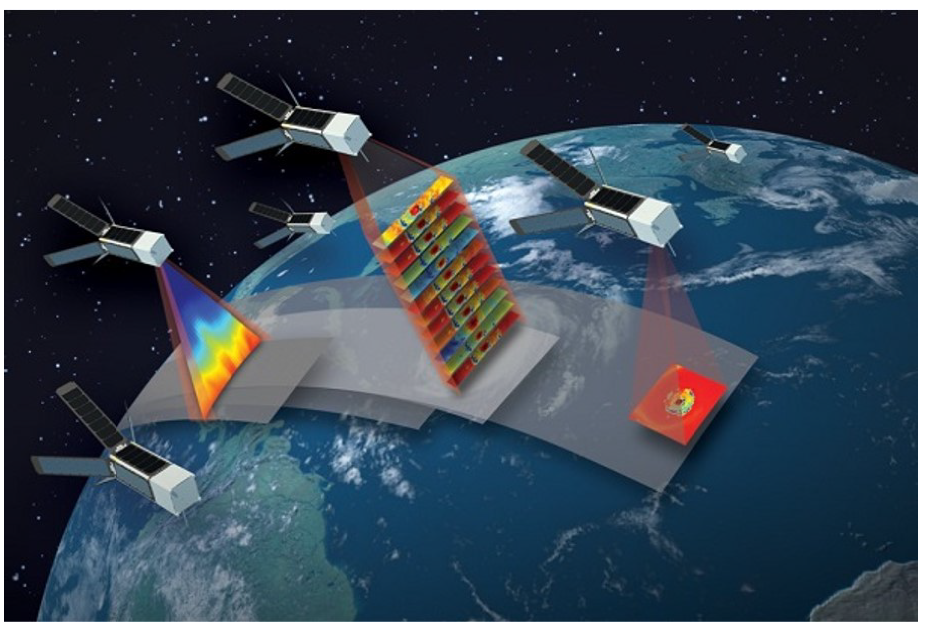
Figure 1. TROPICS project.
Drones 06 00348 g001
Figure 2. The rotating formation illustration of multi-spacecraft systems.
Drones 06 00348 g002
Figure 3. Curve of prescribed performance function.
Drones 06 00348 g003
Figure 4. The communication topology among the multi-spacecraft system.
Drones 06 00348 g004
Figure 5. Trajectory of all spacecraft under the inertial coordinate system.
Drones 06 00348 g005
Figure 6. Rotating formation error time response curve of all spacecraft under the controller (19).
Drones 06 00348 g006
Figure 7. Angular velocity response curves for all spacecraft.
Drones 06 00348 g007
Table 1. Parameter of multi-spacecraft system.
Spacecraft NumberInitial States ( p i ( 0 ) )Derivative of
the Initial States
( q i ( 0 ) )
Desired States
( p id ( 0 ) )
1 [ 6 , π 3 ] T [ 3 , 0 ] T [ 4 , 0.4 t ] T
2 [ 8 , π 3 ] T [ 1 , 7 ] T [ 4 3 , 0.4 t + π 6 ] T
3 [ 6 , 0 ] T [ 4 , 2 ] T [ 4 , 0.4 t + π 3 ] T
4 [ 10 , π 6 ] T [ 0 , 5 ] T [ 2 3 , 0.4 t + π 6 ] T
Table 2. Performance indicators of multi-spacecraft system.
SpacecraftLimitedPracticalDesired
NumberOvershotOvershotSteady-State Error
1 100 % 0.01 % 1.5 × 10 4
2 100 % 0.01 % 1.5 × 10 4
3 100 % 0.0075 % 1.5 × 10 4
4 100 % 0.175 % 1.5 × 10 4
SpacecraftPracticalDesired ConvergencePractical
NumberSteady-State ErrorTime (s)Convergence Time (s)
1 1.2 × 10 5 10 9.82
2 1.4 × 10 5 10 9.88
3 9.2 × 10 6 10 9.83
4 8 × 10 6 10 9.86
Publisher’s Note: MDPI stays neutral with regard to jurisdictional claims in published maps and institutional affiliations.