Article

Design and Implementation of Sensor Platform for UAV-Based Target Tracking and Obstacle Avoidance

1
Department of Aerospace Engineering, Sejong University, 209, Neungdong-ro, Gwangjin-gu, Seoul 05006, Korea
2
Department of Mechanical Engineering, New Mexico Institute of Mining and Technology, Socorro, NM 87801, USA
3
Department of Aerospace Engineering, and Convergence Engineering for Intelligence Drone, Sejong University, Seoul 05006, Korea
*
Author to whom correspondence should be addressed.
Drones 2022, 6(4), 89; https://doi.org/10.3390/drones6040089
Submission received: 10 March 2022 / Revised: 22 March 2022 / Accepted: 27 March 2022 / Published: 29 March 2022
(This article belongs to the Special Issue Advances in UAV Detection, Classification and Tracking)

Abstract

:
Small-scale unmanned aerial vehicles are being deployed in urban areas for missions such as ground target tracking, crime scene monitoring, and traffic management. Aerial vehicles deployed in such cluttered environments are required to have robust autonomous navigation with both target tracking and obstacle avoidance capabilities. To this end, this work presents a simple-to-design but effective steerable sensor platform and its implementation techniques for both obstacle avoidance and target tracking. The proposed platform is a 2-axis gimbal system capable of roll and pitch/yaw. The mathematical model that governs the dynamics of this platform is developed. The performance of the platform is validated through a software-in-the-loop simulation. The simulation results show that the platform can be effectively steered to all regions of interest except backward. With its design layout and mount location, the platform can engage sensors for obstacle avoidance and target tracking as per requirements. Moreover, steering the platform in any direction does not induce aerodynamic instability on the unmanned aerial vehicle in mission.

1. Introduction

The emergence of small-scale unmanned aerial vehicles (UAVs) revolutionizes the way missions are conducted in various sectors. Being small in size and agile in their operation, these UAVs can operate in cluttered and confined environments. With the advent of miniature sensors, as well as computer vision and machine learning technologies [1,2,3], these small-scale UAVs can acquire artificial intelligence and be deployed to monitor production processing in complex industrial facilities [4].
The feasibility of deploying small-scale UAVs for missions in urban areas is already proven in various scenarios [5]. Douglas and James [6] discussed the implementation and operational feasibility of such UAVs for law enforcement. As reported in their conclusion, the use of small UAVs in both urban environments and open areas is feasible. Romeo [7] reported that, in 2020 alone, more than 1500 public safety departments of the United States implemented small UAVs as situation awareness tools.
However, small-scale UAVs have various technological constraints [8,9,10,11], including insufficient power sources for long flight endurance and limited payload weight. Perry et al. [12] reported that, of all challenges and limitations of small-scale UAVs, the weight constraint is the most serious setback to their technological advancement. Contrary to this, such UAVs are required to have multiple sensors on board to have robust autonomous navigation in urban areas where access to GPS-based navigation is unreliable. The requirement of multiple sensors onboard a small UAVs also poses challenges, such as sensors data fusion and the high purchase cost of the sensors. Jixian [13] reported that acquiring effective methodology for multi-sensor data fusion and interpretation is not yet realized. Bahador et al. [14] also reported various reasons for the challenges in multi-sensor data fusion, including data imperfection, inconsistent data, and variation in operational timing of sensors.
The hurdle to overcome is, therefore, not only the weight but also the complexity of multi-sensor data fusion. In resolving the aforementioned setbacks—flight endurance, weight constraint, and sensors data fusion—reducing the number of sensors is a promising approach. In closing the gap between the need to scan the surrounding environment and reducing number of sensors, it is necessary to implement a movable sensor platform that enables few sensors to scan the environment around the UAV.
There are various movable sensor platforms (gimbals) which are operating successfully in the objectives they are designed and deployed for [15,16,17]. Steerable degrees of freedom (DoF) and mount locations dictate the design objectives of the sensor platforms. Most, if not all, of the existing platforms are UAV-belly-mounted platforms; hence, their feasibility for obstacle avoidance, which is critical for operating in urban areas [18,19,20], is controvertible. When obstacles such as high, multi-storey buildings are encountered, there is the possibility that the UAV has to pass over the buildings. In such cases, scanning the environment above the UAV is required. Belly-mounted gimbals can not engage sensors for obstacle detection in such scenarios. Consequently, this work presents a simple-to-design but effective solution for improving the performance of the sensor platforms with a different mount location and orientation for small-scale, fixed-wing UAVs.
For the designed gimbals to operate as desired, mathematical models that control their dynamics are essential. Mohd et al. [21] developed a mathematical model for a two-axis gimbal system with pan-and-tilt DoF. The developed mathematical model is specific to the design, mount location, and orientation of the gimbal system. For the same DoF gimbal system, but with different orientation, Alexander et al. [22] developed a specific mathematical model for the gimbal. For the control of the dynamics of a three-axis gimbal system, Aytaç and Rıfat [23] formulated a unique mathematical model for the system. The proposed sensor platform has unique design layout, mount location, and orientation. Therefore, a mathematical model specific to this platform is formulated and a control algorithm is developed based on the mathematical model.
Constrained to these requirements, this paper proposes steerable sensor platform design and its implementation techniques, as described in subsequent sections. A problem statement and the methodology are presented in Section 2. The custom sensor platform design and its operational modes and techniques are described in Section 3. In Section 4, the mathematical model that governs dynamics of the platform is derived. In Section 5, the designed platform performance testing methods are discussed. Results and discussions are given in Section 6. Conclusions and future works are given in Section 7.

2. Problem Statement and Methodology

The use of small-scale UAVs in urban areas incurs required but incompatible features. A small-scale UAV is required to operate in urban areas because its potential danger in the event of a crash is low. To autonomously navigate in urban areas, this UAV requires multiple sensors onboard. However, small-scale UAV is highly weight-constrained. Therefore, the plausible approach to alleviate the incompatibility is to reduce the number of sensors onboard the UAV. The approach to reduce the number of sensors onboard the UAV remarkably resolves multiple issues: payload weight, technical challenge of sensors integration, computational burdens of data fusion, and sensors purchase costs.
Rather than rigidly mounting multiple sensors on different sides of the UAV, it is feasible to mount few sensors on a movable platform, so that the sensors can be steered to scan regions of interest. There are various movable sensor platforms available for small-scale UAVs. However, they are designed to be mounted under the belly of the UAVs. This can be conceivable for target tracking mission. However, since obstacle avoidance is one of the critical requirements for missions in urban areas, such belly mounting is not feasible. Moreover, belly-mounted platforms induce aerodynamic instability to certain extent. The flight control surfaces have to counteract this instability, which drains the power source.
The aforementioned studies imply that, for civilian UAVs operating in urban areas, there has to be a new design of sensor platform that can engage sensors for obstacle avoidance, in addition to other requirements. The design and mount location of the sensor platform should enable sensors for obstacle avoidance and for monitoring a region of interest or track moving target.
Taking these into consideration, this research work presents a design and technical implementation of low-cost and light-weight steerable sensor platform that can be mounted on the nose of fixed-wing VTOL UAVs. The design and mount location of the proposed sensor platform are such that the platform can engage the sensors for both obstacle avoidance and target tracking. In addition to the tracking and avoidance capabilities, the platform is designed with the intention that it does not induce any aerodynamic instability while engaging sensors in different direction or being at idle state.

3. Custom Platform Design

Prior to the design of a sensor platform, the type of the intended UAV on which the platform is to be mounted should be known. The mount location of the platform is also determined by the type of mission the UAV is design for.

3.1. Airframe Selection

The selection of UAV type depends on the mission requirement. As indicated in the title of this work, the UAV is required to have target tracking capability. For target tracking, a UAV has to cruise with high speed that exceeds the speed of the potential target. A fixed-wing UAV is appropriate for this mission. However, the challenge that comes with fixed-wing UAVs is the requirement of runway for take-off and landing, as well as the very low stall speed in the case when the target being tracked is moving slowly. As law enforcement operations are often conducted in urban areas, constructing runways in every law enforcement compound is infeasible. Moreover, law enforcement missions, such as crime scene monitoring, need a UAV with hovering capability. Such UAVs often have a multicopter-type airframe, which lacks high cruise speed.
Referring to the aforementioned requirements, a hybrid of the multicopter and fixed-wing UAVs is compulsory. A VTOL UAV can change mode from multicopter to fixed-wing or vice versa depending on the status of the target being tracked, mission type, and the environment it is flying in. Furthermore, VTOL UAV does not require runway or launch pad for take-off or trap net for landing as the law enforcement offices are often in highly populated cities. As a result, a fixed-wing UAV with vertical take-off and landing (VTOL) capabilities is selected as preferable airframe.

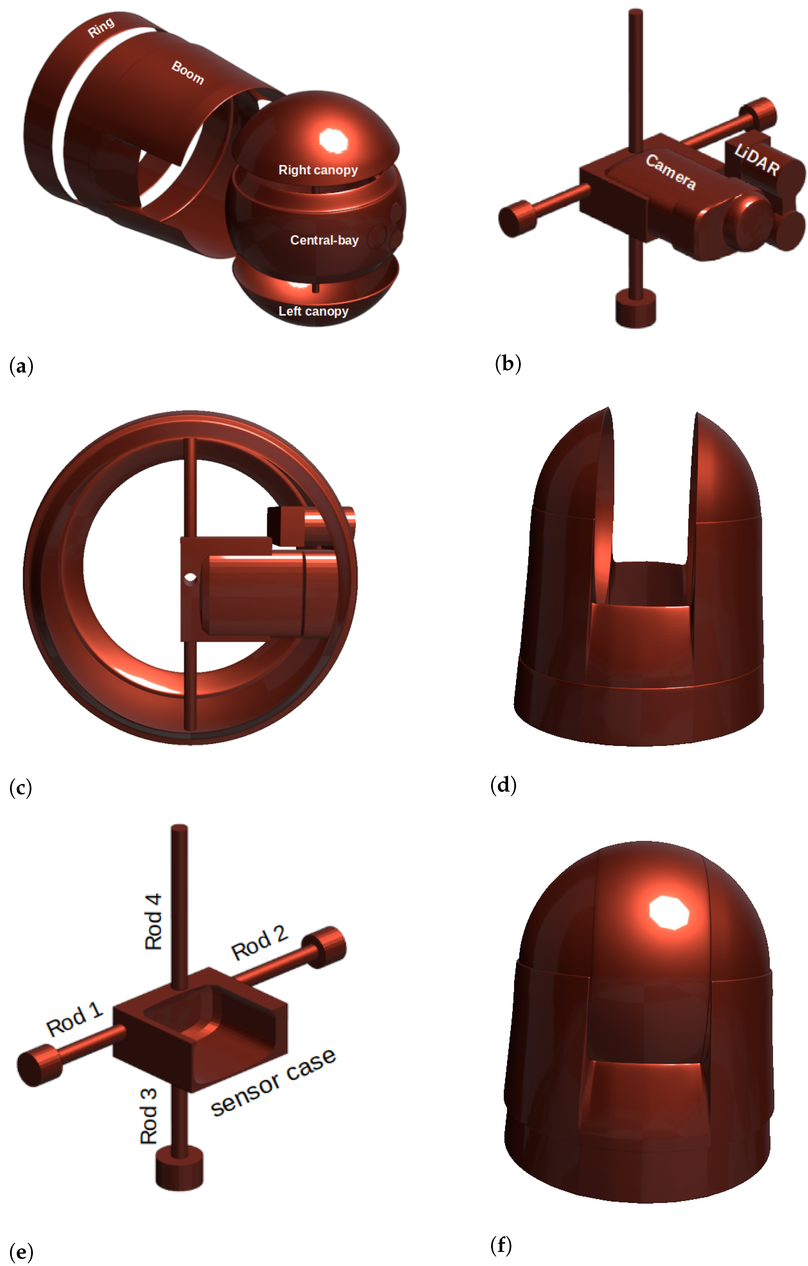
3.2. Platform Design

To the knowledge of the authors, there is no extant steerable sensor platform designed to be nose-mounted on a fixed-wing VTOL UAV for missions requiring obstacle avoidance and target tracking. To fill this gap, a custom sensor platform is designed and its implementation techniques are explained. The sensor platform, presented in this work, is designed in such a way that it can be mounted on the nose of a UAV and, hence, has better aerodynamic efficiency and capabilities to scan environments around the UAV except the backside, which is not important for either target tracking or collision avoidance. Moreover, a simple platform layout that avoids complex design philosophy and control system is preferred to reduce the platform design and manufacturing burdens as well as the required material purchase costs. This is appropriate for making the purchase cost of small-scale UAVs affordable. For the design of the sensors platform presented in this study, blender version 2.91—an open source 3D modeling software—was used. The designed components of the platform and their assembly are shown in Figure 1. The two quarter spherical shells (canopies) and the central bay make a full spherical shell of diameter 138.6 mm. The two canopies, the central bay, boom, and ring components, shown in Figure 1a, form the complete sensor platform. This platform is designed in such a way that it carries a Sony FDR-X3000 camera for imagery data input and LIDAR lite v3 sensor for obstacle ranging. Both the camera and the LiDAR are mounted on the central bay of the platform. They are mounted on sensor case, as shown in Figure 1b.
The inner gimbal, comprising the central bay, the camera, the camera case, LIDAR, and the rods, is shown in Figure 1c. These components are fixed to one another and the pitch/yaw as a single rigid body. The outer gimbal is composed of the boom and the two canopies, as shown in Figure 1d. The four rods, shown in Figure 1e are used to connect the sensor case to the inner gimbal as well as the inner gimbal to the outer gimbal. Rod 1 and rod 2 connect the sensor case to the inner gimbal, and rod 3 connects the inner gimbal to the outer gimbal. The servo motor (not shown here) is connected to rod 4 to control the pitch/yaw motion of the inner gimbal. The inner has grooves that maintain the pitch/yaw smoothly on the rims of the two canopies. The roll motion of the outer gimbal is controlled by a servo motor fixed to the nose of a UAV (not shown). The outer gimbal rolls with its groove, sliding inside the ring. The ring is the part of the platform that is fixed to the nose of UAV. The assembled platform is shown in Figure 1f. The detailed specification of the designed sensor platform is given in Table 1.

3.3. Platform Implementation Techniques

The platform is designed with the intention that it enables onboard sensors scan the environment around a UAV for both obstacle avoidance and target tracking purposes. To this end, the appropriate mount location of the platform is on the nose of the fixed-wing VTOL UAV. The platform operation technique relies on two servo motors capable of steering the platform to all possible directions. Servo motors are implemented for gimbal control, though it induces vibration, unlike the brushless motors often used for gimbal control. The implementation of servos reduces both payload weight and purchase cost as compared with brushless motors. Moreover, since the objective of this platform design is for target tracking and collision avoidance, the image quality is not as big a concern as it is for other mission objectives such as aerial photography. Dampers are used to reduce the vibration issue. One servo is fixed to the nose of the UAV and the other servo is fixed to the right canopy of the platform. Both the right and the left canopies are fixed to the outer gimbal of the platform. The servo fixed to the nose of the UAV controls the rolling movement of the platform about the x-axis and the servo—fixed to the right canopy of the platform—controls the pitch or yaw movement of the inner gimbal of the platform about the y-axis. These roll and pitch/yaw directions of the platform are shown in Figure 2.
The two servos control the movement of the platform independently. The roll in the platform tilts inner gimbal. If the platform roll angle is 0 , then the inner gimbal can pitch either up or down. If the platform rolls by ± 90 (clockwise or anti-clockwise), then the inner gimbal can yaw either left or right. With such configuration, the platform is capable of rolling in the range of [ 90 , + 90 ] and pitching or yawing in the range of [ 90 , + 90 ] .
To monitor the environment above or below the UAV, only the inner gimbal pitches up or down, while the other components of the platform remain tied to the UAV. To monitor the environment either to the left or to the right of the UAV, the whole platform has to first roll, followed by the yawing of the inner gimbal. The combination of rolling of the whole platform and pitching/yawing of the inner gimbal enables the UAV to monitor any direction. In such way, the regions of interest, except the rear side of the UAV, can be scanned making use of only two servos. In all these engagements, there is no aerodynamic instability due to the movement of the platform.
The designed platform has generic applications that include the mission objectives of all belly-mounted platforms. Furthermore, although the design requirements of the sensor platform are constrained to target tracking and obstacle avoidance capabilities, with its wide range of angle of view, the platform has potential applications for various missions, such as door-to-door package delivery, infrastructure monitoring, sewer inspection, and as a visual guide for aerial-robot-based repair and painting of high, multi-storey buildings.

4. Platform Motion Control

4.1. Kinematics of the Platform

The kinematics of the platform deals with determination of linear and angular positions, velocities, and acceleration of the two gimbals—the inner and outer gimbals—in such a way that the attached sensors focus on a region of interest. The orientations of the two gimbals in their idle states are shown in Figure 3. The origin of the camera frame (C) is on the rim of gimbal 2 and the axes of the gimbals and the camera are as shown in the figure. The hidden axes of these frames are generated by right-hand rule.
The two gimbals are considered as rigid bodies whose motions are constrained through joints, and the motion of one affects the other. As shown in Figure 4a, the origin of the body frame b is located at center of gravity of the UAV, the relative position of frame G 1 with respect to body frame is ( d 1 x , 0 , d 1 z ), and the relative position of frame G 2 with respect to frame G 1 is ( d 2 x , 0 , 0 ). Gimbal 2 is attached to gimbal 1 with a revolute joint at frame G 2 and constrained to rotate about an axis perpendicular to x 2 z 2 -plane. Gimbal 1 is attached to the UAV (henceforth: body) frame with revolute joint at frame G 1 and rotates in the y 1 z 1 -plane, as shown in Figure 4b. α and β represent arbitrary roll and pitch angles made by gimbal 1 about the body frame and gimbal 2 about the gimbal 1 frame, respectively.

4.1.1. Coordinated Frame Transformation

Coordinated frame transformation is necessary, where any value obtained in one frame can be derived in another frame. Let the coordinate frame axes of the camera are represented by ( x c , y c , z c ) where z c -axis is parallel to x 2 -axis and x c -axis is parallel to y 2 -axis. Therefore, any known information in the camera frame can be transformed to the gimbal 2 frame, as follows:
2 T c = [ 2 R c 2 d c 0 1 × 3 1 ] = [ 0 0 1 r 1 0 0 0 0 1 0 0 0 0 0 1 ]
where 2 T c is a homogeneous coordinate transformation from camera frame to frame G 2 . 2 R c and 2 d c are the orientation and translation of the camera frame, with respect to gimbal 2 frame, respectively, and r is the radius of gimbal 2. Similarly, the homogeneous coordinate transformation from G 2 frame to G 1 frame and from G 1 to body frame, respectively, are as follows:
1 T 2 = [ cos β 0 sin β d 2 x 0 1 0 0 sin β 0 cos β 0 0 0 0 1 ] and b T 1 = [ 1 0 0 d 1 x 0 cos α sin α 0 0 sin α cos α d 1 z 0 0 0 1 ]
Following the two transformations given in Equation (2), the transformation from gimbal 2 to body frame is as follows:
b T 2 = b T 1 1 T 2 = [ cos β 0 sin β d 1 x + d 2 x sin α sin β cos α sin α cos β 0 cos α sin β sin α cos α cos β d 1 z 0 0 0 1 ]
b T 2 and b T 1 shall be utilized in Section 4.2 to transform the center of mass of each gimbal into body frame. Using to Equations (1) and (3), the transformation from the camera frame to body frame is as follows:
b T c = b T 2 2 T c = [ 0 sin β cos β r cos β + d 1 x + d 2 x cos α sin α cos β sin α sin β r sin α sin β sin α cos α cos β cos α sin β r cos α sin β + d 1 z 0 0 0 1 ]
Information such as target location in camera image frame are transformed to body frame using Equation (4).

4.1.2. Jacobian Transformation

The ultimate objective of camera gimbals is to keep the camera focused on the region of interest while a carrier UAV undergoes different flight maneuvers. To keep the camera in the desired position and orientation, the angular positions and velocities of joints of the gimbals have to vary accordingly. That means that the position and orientation of the origin of the camera frame can be defined in terms of the joint angular positions α and β . The Jacobian transformation handles such interdependence. Let the position vector of the origin of camera frame—with respect to the i = ( G 2 , G 1 , b ) frame–be represented as i r c . As the gimbals undergo roll, pitch, and yaw motions, the origin of the camera frame traces the 3D space. Hence, the position vector i r c can be decomposed as follows:
i r c = [ i x c i y c i z c ]
The same position of the camera frame can be expressed in j frame as follows:
j r c = j T i i r c
where j T i is the homogeneous coordinate transformation from the i frame to the j frame.
Referring to Figure 4a, the position of the camera origin with respect to the G 2 frame is given as follows:
2 X c = [ r 0 0 1 ]
This position can be transformed to the G 1 and b frames as follows:
1 X c = 1 T 2 2 X c = [ r cos β + d 1 x 0 r sin β 1 ] and b X c = b T 2 2 X c = [ r cos β + d 1 x + d 2 x r sin α sin β r cos α sin β + d 2 z 1 ]
where the transformation matrices 1 T 2 and b T 2 , given in Equations (2) and (3), are used. The position vectors 1 X c and b X c are functions of the angular positions α and β , as shown below.
1 X c = [ 1 x c ( β ) 1 y c ( β ) 1 z c ( β ) 1 ] = [ r cos β + d 2 x 0 r sin β 1 ] and b X c = [ b x c ( β ) b y c ( β ) b z c ( β ) 1 ] = [ r cos β + d 1 x + d 2 x r sin α sin β r cos α sin β + d 2 z 1 ]
Referring to Equation (9), translational Jacobian matrices of the following forms are derived as follows:
J i X c : = [ i x c α i x c β i y c α i y c β i z c α i z c β 0 0 ] i = 1 , b
This implies that
J 1 X c = [ 0 r sin β 0 0 0 r cos β 0 0 ] and J b X c = [ 0 r sin β r cos α sin β r sin α cos β r sin α sin β r cos α cos β 0 0 ]
where J 1 X c is translational Jacobian matrix that relates the angular position ( β ) of gimbal 2 to the camera position, and J b X c is translation Jacobian matrix that relates the combined variation of angular positions ( α ) and ( β ) of gimbal 1 and gimbal 2, respectively, to the camera position.
In addition to the position of the origin of camera frame, its orientation is important. The angular rotations of the origin of the camera frame with respect to G 1 and b frames, respectively, are as follows:
1 Θ c = [ 1 θ x c 1 θ y c 1 θ z c 1 ] = [ 0 β 0 1 ] and b Θ c = [ b θ x c b θ y c b θ z c 1 ] = [ α β 0 1 ]
Applying the differential relations shown in Equation (10) into Equation (12), the rotational Jacobian matrices of these angular rotations are as follows:
J 1 Θ c = [ 0 0 0 1 0 0 0 0 ] and J b Θ c = [ 1 0 0 1 0 0 0 0 ]
The linear and angular velocities of the origin of camera frame can be obtained from the time derivatives of linear position and angular rotation, given by Equations (9) and (12), respectively. These velocities of the origin of the camera frame can be expressed as functions of the angular velocities α ˙ and β ˙ of gimbal 1 and 2, respectively.
i Λ ˙ c = i Λ ˙ c α α ˙ + i Λ ˙ c β β ˙ Λ = X , Θ and i = 1 , b
Using Equation (14), the linear velocities of the origin of the camera frame with respect to G 1 and b frames are the following:
[ 1 x ˙ c ( β ) 1 y ˙ c ( β ) 1 z ˙ c ( β ) 0 ] = J 1 X c [ α ˙ β ˙ ] and [ b x ˙ c ( β ) b y ˙ c ( β ) b z ˙ c ( β ) 0 ] = J b X c [ α ˙ β ˙ ]
where J 1 X c and J b X c are given in Equation (11).
Similarly, applying Equation (14), the angular velocities with respect to G 1 and b are as follows:
[ 1 θ ˙ x c 1 θ ˙ y c 1 θ ˙ z c 1 ] = J 1 Θ c [ α ˙ β ˙ ] and [ b θ ˙ x c b θ ˙ y c b θ ˙ z c 1 ] = J b Θ c [ α ˙ β ˙ ]
where J 1 Θ c and J b Θ c are given in Equation (13), respectively.

4.2. Dynamics of the Platform

The platform is considered as constituent of two rigid bodies: gimbal 1 and gimbal 2. To control the dynamics of these gimbals, a governing mathematical model is developed. Both gimbals are set into rotation by the desired torques applied through their respective servo motors so as to focus the sensors on a given region of interest. Each gimbal has its own inertia with both static and dynamic mass unbalance. The dynamics of one of the gimbal affects the other. Moreover, the change in attitude of a UAV on which the platform is attached also affects the dynamics of the gimbals. The platform controller to be developed from the mathematical model has to take all these effects into consideration and keep the sensors focused on region of interest.
The gimbal 2 rotates about y 2 -axis that passes through the gimbal’s geometric center and gimbal 1 rotates about x 1 -axis that, also, passes through the gimbal’s geometric center. Due to the sensors mounted on gimbal 2, the center of mass is offset by certain amount from the geometric center. Similarly, due to gimbal 2 and servo motors attached to gimbal 1, the center of mass of gimbal 1 is shifted off the center. Therefore, the off-diagonal elements of inertia matrices of the two gimbals are non-zero. Let, the mass moment of inertia about the respective mass centers of the gimbals are given by the following:
i I j = [ i I j x i I j x y i I j x z i I j x y i I j y i I j y z i I j x z i I j y z i I j z ]
where j = 1 , 2 represents the mass moment of inertia for gimbal 1 and gimbal 2, respectively, and i represents the coordinate frame with respect to which the moment of inertia is measured. The Lagrangian equation of motion of the sensor platform is given as follows:
d d t ( L ϑ ˙ j ) L ϑ j = Q j where L = K V
K and V are the kinetic and potential energies, Q is non-conservative force that includes the desired force applied by the servo motors on the gimbals and the undesired external forces. The joint angular position ϑ = ( α , β ) and ϑ ˙ represents their time derivative.
Kinetic energy of gimbal j is given as follows:
K j = 1 2 b X ˙ j T m j b X ˙ j + 1 2 b Θ ˙ j T b I j b Θ ˙ j T
where the first and the second terms on the right hand side of Equation (19) represent translational and rotational kinetic energies of center of mass of the gimbal with respect to body frame. b X ˙ j and b Θ ˙ j are the linear and angular velocities of the center of mass with respect to body frame. These velocities can be expressed in terms of joint angular velocities ϑ ˙ by applying translational and rotational Jacobian matrices of the form given in Equations (15) and (16). Applying the corresponding Jacobian matrices to Equation (19), the total kinetic energy of the gimbals, in terms of joint angular velocities, is expressed as follows:
K = 1 2 ϑ ˙ T D ϑ ˙
where D is the n × n inertial-type matrix composed of translational and rotational inertia of the following form:
D ( ϑ ) = j 2 ( J X j T m j J X j + 1 2 J Θ j T b I j J Θ j )
where J X j and J Θ j are Jacobian matrices that transform joint angular velocities ϑ ˙ j of gimbal j into translational and rotational velocities of the gimbal’s center of mass. b I j is the mass moment of inertia of the gimbal about its center of mass as expressed in the body frame and m j is the mass of the gimbal.
To determine the potential energy (V) of a gimbal, one must calculate the acceleration due to gravity of the center of mass of the gimbal. Acceleration due to gravity is a vector pointing into the Earth’s center. In gimbal 2 frame, the acceleration due to gravity is as follows:
2 G = [ g sin β 0 g cos β ]
where β is the current angular position of gimbal 2 as shown in Figure 4a. The gravity vector acts at the center of mass of the gimbal. The gravity vector in body frame can be obtained using the coordinate transformation matrix given in Equation (3). However, the first three yaws and the three columns of the matrix are used to transform the gravity vector, since the translation vector has no effect on the gravity vector. Therefore,
b G = [ g sin 2 β g sin α ( cos 2 β sin 2 β ) g cos α ( cos 2 β sin 2 β ) ]
The potential energy of gimbal j, with respect to the body frame, is given as follows:
V j = m j b G T b r j
where b r j is the position vector of the center of mass of gimbal j with respect to the body frame. The total potential energy of the sensor platform is, thus, given as follows:
V j = i = 1 2 m i b G T J X i j ϑ
where i represents the coordinate frame in which inertia measurement was made before it is transformed into body frame. For j > i , j’s column of matrix J is zero. The position of the center of mass for each gimbal is obtained using the CATIA inertia measuring tool.
Substituting the expressions of Equations (20) and (25) into Equation (18), and after rearranging the terms, the dynamic equation of motion of the platform is as follows:
i = 1 2 D j i ϑ ¨ i + k = 1 2 l = 1 2 ( D j k ϑ l 1 2 D k l ϑ j ) ϑ ˙ k ϑ ˙ l + i = 1 2 m i b G T J X i j = Q j
where the first term represents the reaction of gimbals to external force Q j , the second term is a velocity coupling force, and the third term represents gravitational force. Let
H j k l : = k = 1 2 l = 1 2 ( D j k ϑ l 1 2 D k l ϑ j ) ϑ ˙ k ϑ ˙ l
and
Γ j : = i = 1 2 m i b G T J X i j
With the definitions given in Equations (27) and (28), Equation (26) can be written in compact form as
ϑ ¨ = D 1 [ Q ( H + Γ ) ]
Let the state–space model be given as follows:
χ = [ ϑ ϑ ˙ ] = [ α β α ˙ β ˙ ] χ ˙ = [ ϑ ˙ ϑ ¨ ] = [ α ˙ β ˙ α ¨ β ¨ ]
The state–space model can be expressed in terms of Equation (29), as follows:
[ ϑ ˙ ϑ ¨ ] = [ ϑ 2 × 1 D ( ϑ 2 × 1 ) 1 [ Q ( H + Γ ( ϑ 2 × 1 ) ) ] ]
The platform control algorithm makes use of the above equations to determine the required angular positions and velocities of the gimbals. The inertia matrices of the two gimbals are obtained from their CATIA models. The inertial matrices of the gimbals are obtained with respect to their respective coordinate frame and transformed into body frame.

5. Platform Performance Validation Test

To test the performance of the proposed sensor platform, the platform is nose-mounted on a fixed-wing UAV, which is commanded to randomly change its flight status. Under such random changes in flight status, the responses of the platform in its collision avoidance and target tracking operational modes are tested. In this phase of performance validation, the tests are conducted in a virtual environment using SITL simulation.

SITL-Based Performance Tests

Prior to the actual deployment of a new model, conducting a simulation-based performance test is common practice. There are various SITL simulation frameworks available for use. For the proposed sensor platform performance tests, PX4 flight control firmware-based SITL simulation framework was selected. This PX4 firmware has ready-made models of various vehicles, LiDar Lite, and camera sensors required by the proposed sensor platform.
To reproduce the actual platform control techniques described in Section 3.3, the designed platform model is nose-mounted on a standard VTOL UAV model of PX4 firmware, as shown in Figure 5. The outer gimbal of the platform is attached to the nose of the UAV with revolute joint in roll and the inner gimbal of the platform is attached to the right canopy of the platform with revolute joint in pitch/yaw. The two revolute joints represent the two servo motors that control the sensor platform in real flight scenario. Both joints can rotate in the range of [ 90 , + 90 ] . The PX4 firmware models of camera and LIDAR sensors are mounted on the inner gimbal of the platform. Inertia measurement unit (IMU) sensor is mounted on the inner gimbal and the attitude angles of the sensor platform obtained through IMU are used to determine the gravity vector on the gimbals of the platform.

Gazebo Simulation Environment

Gazebo is an open source three dimensional environment simulator that is rich in realistic features of both indoor and outdoor environments. It implements open dynamics engine (ODE) that handles rigid body dynamics simulation and collision detection. The dynamics of UAV and its sensor platform system are governed by this ODE. Sensor models are attached on the UAV and sensor platform to acquire their dynamics information. These sensor information are sent to flight control firmware. Based on the received information, the flight control firmware decides actuator commands and controls the dynamics of the UAV and the sensor platform. PX4 firmware is already integrated to Gazebo simulation environment and have been widely used by many researchers over the years [24,25,26].
Access to the ODE and other functionalities of gazebo is through gazebo plugins. The plugin is a code from which a shared library is generated. Communication between PX4 flight control firmware and gazebo simulation environment are enabled through the generated plugin libraries. A custom gazebo plugin that enables the PX4 firmware to acquire information about the sensor platform and send actuator commands to the platform servos is written by the authors and implemented in the SITL simulation process. The custom plugin takes the current angular positions and velocities of the gimbals as inputs and applies a force required to steer the platform to a desired region of interest. A simple PID controller is used in the plugin to control the motion of the gimbals. The position, mass, and inertial properties of all components of sensor platform, including that of FDR-X3000 camera and LiDAR sensors, are incorporated to simulation description format (SDF) file of UAV model and their dynamics are simulated by gazebo ODE.
A custom gazebo plugin module that controls the revolute joints was written and included to SITL_gazebo plugins of PX4 firmware. To send actuator outputs to the joints (servos), a custom mixer was defined and included to SITL_mixers of the firmware. For obstacle avoidance, the custom mixer takes normalized velocity vector of the UAV and provides actuator outputs. For target tracking, a robot operating system (ROS)-based node is written in ROS workspace. This node subscribes to current location of UAV in the gazebo simulation environment and generates simulated target locations so that the platform steers the sensors to lock-on/track a virtual target on those locations. The relative position vector of the virtual target with respect to the UAV is determined from the current UAV location and the generated virtual target location. Based on the relative position vector, the required roll, and the pitch/yaw angles are calculated and published to actuator control topic of PX4 firmware. The custom mixer takes the actuator control values and produces corresponding actuator output that controls the joints.
The platform’s operational mode switching from obstacle avoidance to target tracking or vice versa is enabled through parameter tuning and flight status of the UAV. A parameter is defined in the mc_att_control module of the PX4 firmware and mapped to radio control (RC) transmitter for tuning. The mc_att_control module is, also, customized with conditional statements. For instance, the following:
The platform engages the sensors for obstacle avoidance if the parameter is tuned to be in a certain range of values and UAV flight status is in either of the following flight modes:
automatic take-off;
automatic landing;
fly to a known location of interest (e.g., crime scene);
return-to-launch.
Under the condition that the UAV is in hover or altitude control mode, manual override of the mode is disabled and the platform is set to ready to be manually steered by RC transmitter to search for an intended target. Although manual override is disabled during a UAV’s hover and altitude control mode, flight mode switching is active and can be carried out through either aground control unit or an RC transmitter.
If a target is identified and the parameter is tuned to certain range of values, then the platform locks on the target and pursues it. The flight mode is then switched to mission so that the UAV tracks the target.

6. Results and Discussion

6.1. Obstacle Avoidance

When the UAV is on the ground, the platform disengages the sensors and acquires a horizontal orientation, as shown in Figure 6a. When a take-off command is given to the UAV, it takes-off with the sensor platform pitched by 90 upward, as shown in Figure 6b, till it attains its designated altitude. Soon, the UAV attains the intended altitude and enters hover mode, and the platform automatically disengages pitching, as shown in Figure 6c, and is ready for either manual steering to search for target or cruises to the region of interest in the obstacle avoidance mode. During landing, as shown in Figure 6d, the platform pitches the sensors down by 90 to scan the environment below the UAV.
In Figure 7, an inertial measurement unit (IMU) is mounted on inner gimbal of the platform and the pitch responses of the platform, to take-off and land commands, are compared to the IMU reading. There is a complete overlap between the IMU reading and the pitch angle variation of the sensor platform.
In order to further test the pitch response of the platform to random changes in the flight status of the UAV, take-off and land commands are given to the UAV at random altitudes. Therefore, the UAV aborts its flight status randomly and the platform has to respond to that random changes. The pitch response of the platform is checked with respect to the velocity vector of the UAV as shown in Figure 8.
The negative velocity of the UAV corresponds to the ascending mode, whereas the positive velocity is for the descending mode. Likewise, the negative and positive pitch angles correspond to the pitch up and down, respectively, of the inner gimbal of the platform. As can be seen in the figure, the platform responds to the change in the direction, but not the magnitude, of the velocity of the UAV. This shows that the platform is not bothered by how fast or slow the UAV is flying but by the change in the flight course.
The performance of the platform is also tested while a UAV is navigating through waypoints. The waypoints shown in Figure 9 are sent to the UAV. In its mission to fly to the destination, the UAV is commanded to take-off to altitude of 10 m, descend to 5 m, roll to the left for 30 m (along x-axis), pitch forward about 15 m (along y-axis), and then roll and pitch (simultaneously) towards the destination, which is 15 m along the y-axis and 15 m along the x-axis in the negative direction. Therefore, in this flight path, the performance of the sensor platform in roll, pitch, and combination of roll–yaw can be tested.
For obstacle avoidance, the sensor platform has to be steered towards the velocity vector of the UAV so that the sensors focus on the flight course. As shown in Figure 10, the UAV is commanded to fly to the destination along the given waypoints, while the roll, pitch, or yaw movement of the platform remains aligned with the velocity vector of the UAV. Referring to the figure, during take-off and descend, the platform roll angle remains zero and the pitch angle is 1.5 rads ( 90 ). At 19.05 s of simulation time, the UAV starts to roll side-way along x-axis with velocity V x while other components of the velocity ( V y and V z ) remain zero. The platform rolls right and yaws left by + 90 s to orient the sensors along flight course of the UAV. After 31.71 s of simulation time, the UAV completes rolling and changes its flight course towards the y-axis (forward). Following this change in flight course, the platform orients the sensors forward ( 0 ) until the UAV completes 15 m of forward flight. The forward flight is completed at 43.76 s of simulation time where the V y velocity component drops to zero. The remaining mission is to fly to the destination that requires the UAV to simultaneously fly forward and roll sideways. In this flight course, the platform has to roll left and yaw right as shown in the simulation time range from around 0.47–0.6 s

6.2. Target Tracking

Target tracking or lock on target responses of the sensor platform are shown in Figure 11, where the UAV is commanded to randomly ascend and descend. The platform remains focused on a target located 30 m in front of the UAV. The response of the sensor platform to UAV’s altitude change is immediate. The altitudes at which the UAV is commanded to change its flight mode are normalized, where 1 corresponds to altitude of 10 m, to magnify the variation in the platform pitch angle.
The lock-on-target capability of the platform is visualized using the YOLO object detection algorithm that runs in the ROS workspace. As shown in Figure 12, the UAV locks on a target located 30 m in front of it.
The aforementioned waypoints are used to test the target tracking or lock on target performance of the platform. In the lock-on-target operation mode, wherever the UAV is heading, the platform has to keep focusing on the target (destination). This is depicted by the variations in the roll and pitch/yaw angles of the sensor platform as compared to the location of the UAV along the flight path, as shown in Figure 13. The UAV takes-off to altitude of 10 m and descends to 5 m before flying to waypoints. The locations of the UAV in the given waypoints are scaled down by 10% to magnify the variation of roll and pitch/yaw angles of the platform. During take-off and descend modes, the platform pitches so as to lock the sensors on a virtual target located at destination point (30 m forward). After 15 s of simulation time, the UAV rolls left along x-axis keeping its altitude at 5 m. To lock the sensors on the destination point, the platform has to roll left and yaw right, while the UAV is rolling along the x-axis, it recedes from the destination, and hence the roll and yaw angles of the platform increase up to 28.24 s of simulation time. The UAV then heads forward for 15 m up to 35.64 s of simulation time at which the UAV completes rolling left. During this forward flight course, the platform roll angle remains fixed while the yaw angle keeps on increasing so that the sensors remains locked on the target. Then, the UAV rolls right and fly forward, simultaneously, towards the destination up to 45.13 s of simulation time in which the platform yaw angle increases to + 1.5 rads and the roll angle reduces to 0 as the UAV approaches and hovers over the target. At the destination, the UAV hovers over the target with the platform pitching down + 1.5 to remain locked on the target.
In the hover or position hold flight mode of the UAV, the incorporated custom parameters and conditions given in mc_att_control enable a user to manually roll or pitch/yaw the platform, using RC transmitter to search for a target without affecting the attitude of the UAV. Figure 14 shows random manual steering of the sensor platform in search for a target, while the UAV remains level in hover mode. The moment the target is obtained, the user toggles a switch on the RC transmitter that is mapped to a parameter to lock on the target, and the UAV starts to pursue the target.

7. Conclusions and Future Work

The use of small-scale UAVs for law enforcement missions is significantly increasing in cities and towns. However, these UAVs are required to have robust autonomy in executing missions in such areas. This means that the UAVs have to have enough information about the environment they are operating in so as to execute their missions while avoiding collision with potential dangers. Information about the surrounding environment is obtained through sensors onboard a UAV. Often, multiple sensors are rigidly mounted on different sides of a UAV to scan the surrounding environment. However, this practice is not feasible for various reasons, including the following: small-scale UAVs are highly weight-constrained, synchronizing and fusing data of multiple sensors are challenging tasks, and the purchase cost of sensors is high. Therefore, to avoid these setbacks, utilizing movable sensor platforms that can carry few sensors is an indispensable solution. To this end, a movable sensor platform is designed, its technical implementation is described, and the mathematical model that governs its dynamics is derived. The proposed sensor platform design is unique in its capability to engage sensors for collision avoidance and target tracking tasks. Moreover, the design layout and mount location of the platform do not induce aerodynamic instability during all modes of its operation.
The performance of the platform was tested using software-in-the-loop simulations. The simulation tests were based on the two operational modes of the sensor platform: collision avoidance and target tracking. To test the responses of the sensor platform, the UAV was commanded to randomly change its flight modes and cruise in different directions. The results show that the platform effectively steers the sensors in roll, pitch, or yaw directions in response to random change in UAV’s flight mode and flight course.
In our future work, the custom gazebo plugin that controls the dynamics of the platform will be modified to be incorporated to PX4 flight control software. To validate the successful performance tests obtained through software-in-the-loop simulations, the platform, with its sensors, shall be nose-mounted on a fixed-wing VTOL UAV and real flight experiments will be conducted. If required, further improvements shall be carried out on the platform control module to make sure that the operation of the sensor platform is accurate and stable in both of its operational modes.

Author Contributions

In this manuscript, the sensor platform design philosophy and its implementation techniques were performed by A.T.; customization of the PX4 flight control firmware and integration of the sensor platform to software-in-the-loop simulation were performed by M.H.; the preliminary platform design and its performance test methodologies were performed by H.-Y.H. All authors have read and agreed to the published version of the manuscript.

Funding

This work was supported by the Korea Agency for Infrastructure Technology Advancement (KAIA) grant funded by the Ministry of Land, Infrastructure, and Transport (Grant 21CTAP-C157731-02).

Institutional Review Board Statement

Not applicable.

Informed Consent Statement

Not applicable.

Data Availability Statement

Not applicable.

Conflicts of Interest

All authors mentioned in this manuscript were involved in the study from beginning to end. The manuscript was thoroughly reviewed by the authors before being submitted to Drones. This manuscript has not been submitted to another journal for publication.

References

  1. Burgués, J.; Marco, S. Environmental chemical sensing using small drones: A review. Sci. Total Environ. 2020, 748, 141172. [Google Scholar] [CrossRef] [PubMed]
  2. Smith, M.L.; Smith, L.N.; Hansen, M.F. The quiet revolution in machine vision—A state-of-the-art survey paper, including historical review, perspectives, and future directions. Comput. Ind. 2021, 130, 103472. [Google Scholar] [CrossRef]
  3. Agarwal, A.; Kumar, S.; Singh, D. Development of Neural Network Based Adaptive Change Detection Technique for Land Terrain Monitoring with Satellite and Drone Images. Def. Sci. 2019, 69, 474. [Google Scholar] [CrossRef]
  4. Salhaoui, M.; Guerrero-González, A.; Arioua, M.; Ortiz, F.J.; El Oualkadi, A.; Torregrosa, C.L. Smart Industrial IoT Monitoring and Control System Based on UAV and Cloud Computing Applied to a Concrete Plant. Sensors 2019, 19, 3316. [Google Scholar] [CrossRef] [PubMed] [Green Version]
  5. Glaser, A. Police Departments Are Using Drones to Find and Chase down Suspects. Vox. 2017. Available online: https://www.vox.com/2017/4/6/15209290/police-fire-department-acquired-drone-us-flying-robot-law-enforcement (accessed on 28 December 2021).
  6. Murphy, D.W.; Cycon, J. Application for mini VTOL UAV for law enforcement. In Proceedings of the Volume 3577, Sensors, C3I, Information, and Training Technologies for Law Enforcement, Boston, MA, USA, 7 January 1999. [Google Scholar] [CrossRef] [Green Version]
  7. Durscher, R. How Law Enforcement Has Been Using Drones. Government Fleet. 2020. Available online: https://www.government-fleet.com/359403/how-law-enforcement-has-been-utilizing-drones (accessed on 28 December 2021).
  8. Hardin, P.J.; Jensen, R.R. Small-Scale Unmanned Aerial Vehicles in Environmental Remote Sensing: Challenges and Opportunities. J. GISci. Remote Sens. 2011, 48, 99–111. [Google Scholar] [CrossRef]
  9. Geuther, S.; Capristan, F.; Kirk, J.; Erhard, R. A VTOL small unmanned aircraft system to expand payload capabilities. In Proceedings of the 31st Congress of the International Council of the Aeronautical Sciences, Belo Horizonte, Brazil, 9–14 September 2018. [Google Scholar]
  10. Chand, B.N.; Mahalakshmi, P.; Naidu, V.P.S. Sense and Avoid Technology in Unmanned Aerial Vehicles: A Review. In Proceedings of the International Conference on Electrical, Electronics, Communication, Computer and Optimization Techniques, Mysuru, India, 15–16 December 2017. [Google Scholar]
  11. Mukhamediev, R.I.; Symagulov, A.; Kuchin, Y.; Zaitseva, E.; Bekbotayeva, A.; Yakunin, K.; Assanov, I.; Levashenko, V.; Popova, Y.; Akzhalova, A.; et al. Review of Some Applications of Unmanned Aerial Vehicles Technology in the Resource-Rich Country. Appl. Sci. 2021, 11, 10171. [Google Scholar] [CrossRef]
  12. Hardin, P.J.; Lulla, V.; Jensen, R.R.; Jensen, J.R. Small Unmanned Aerial Systems (sUAS) for environmental remote sensing: Challenges and opportunities revisited. GISci. Remote Sens. 2019, 56, 309–322. [Google Scholar] [CrossRef]
  13. Zhang, J. Multi-source remote sensing data fusion: Status and trends. Int. J. Image Data Fusion 2010, 1, 5–24. [Google Scholar] [CrossRef] [Green Version]
  14. Khaleghi, B.; Khamis, A.; Karray, F.O.; Razavi, S.N. Multisensor data fusion: A review of the state-of-the-art. Inf. Fusion 2013, 14, 28–44. [Google Scholar] [CrossRef]
  15. Quigley, M.; Goodrich, M.A.; Griffiths, S.; Eldredge, A.; Beard, R.W. Target Acquisition, Localization, and Surveillance Using a Fixed-Wing Mini-UAV and Gimbaled Camera. In Proceedings of the 2005 IEEE International Conference on Robotics and Automation, Barcelona, Spain, 18–22 April 2005. [Google Scholar]
  16. Kuzey, B.; Yemenicioğlu, E.; Kuzucu, A. 2 Axis Gimbal Camera Design. ResearchGate 2007, 1, 32–39. [Google Scholar] [CrossRef]
  17. Gremsy. Stabilizing Gimbals & Stabilized Camera Mounts for Drones & UAVs. Unmanned System Technology. Available online: https://www.unmannedsystemstechnology.com/company/gremsy/ (accessed on 12 October 2021).
  18. Sánchez, P.; Casado, R.; Bermúdez, A. Real-Time Collision-Free Navigation of Multiple UAVs Based on Bounding Boxes. Electronics 2020, 9, 1632. [Google Scholar] [CrossRef]
  19. Shakhatreh, H.; Sawalmeh, A.; Al-Fuqaha, A.I.; Dou, Z.; Almaita, E.; Khalil, I.M.; Othman, N.S.; Khreishah, A.; Guizani, M. Unmanned Aerial Vehicles: A Survey on Civil Applications and Key Research Challenges. arXiv 2018, arXiv:1805.00881. [Google Scholar] [CrossRef]
  20. Lancovs, D. Broadcast transponders for low flying unmanned aerial vehicles. Transp. Res. Procedia 2017, 24, 370–376. [Google Scholar] [CrossRef]
  21. Ahmad, M.H.; Osman, K.; Zakeri, M.F.M.; Samsudin, S.I. Mathematical Modelling and PID Controller Design for Two DOF Gimbal System. In Proceedings of the 2021 IEEE 17th International Colloquium on Signal Processing & Its Applications (CSPA), Langkawi, Malaysia, 5–6 March 2021. [Google Scholar] [CrossRef]
  22. Isaev, A.M.; Adamchuk, A.S.; Amirokov, S.R.; Isaev, M.A.; Grazhdankin, M.A. Mathematical Modelling of the Stabilization System for a Mobile Base Video Camera Using Quaternions. Available online: http://ceur-ws.org/Vol-2254/10000051.pdf (accessed on 17 February 2022).
  23. Aytaç, A.; Rıfat, H. Model predictive control of three-axis gimbal system mounted on UAV for real-time target tracking under external disturbances. Mech. Syst. Signal Process. 2020, 138, 106548. [Google Scholar] [CrossRef]
  24. Nguyen, K.D.; Nguyen, T.T. Vision-based software-in-the-loop-simulation for Unmanned Aerial Vehicle Using Gazebo and PX4 Open Source. In Proceedings of the 2019 International Conference on System Science and Engineering (ICSSE), Dong Hoi, Vietnam, 20–21 July 2019. [Google Scholar]
  25. Nguyen, K.D.; Ha, C. Development of Hardware-in-the-Loop Simulation Based on Gazebo and Pixhawk for Unmanned Aerial Vehicles. Int. J. Aeronaut. Space Sci. 2018, 19, 238–249. [Google Scholar] [CrossRef]
  26. Omar, H.M. Hardware-In-the-Loop Simulation of Time-Delayed Anti-SwingController for Quadrotor with Suspended Load. Appl. Sci. 2022, 12, 1706. [Google Scholar] [CrossRef]
Figure 1. Platform components and their configuration. (a) Components of the platform; (b) sensors configuration in the platform; (c) inner gimbal; (d) outer gimbal; (e) sensor case and connection rods; (f) assembled platform.
Drones 06 00089 g001
Figure 2. Operational techniques of the platform.
Drones 06 00089 g002
Figure 3. Frames of reference for the gimbals and camera.
Drones 06 00089 g003
Figure 4. Coordinate frame transformation. (a) Side view; (b) front view.
Drones 06 00089 g004
Figure 5. Platform nose-mount on fixed-wing VTOL UAV.
Drones 06 00089 g005
Figure 6. SITL-based platform operation onboard UAV. (a) Platform during UAV arming; (b) platform during UAV take-off; (c) platform during UAV hovering; (d) platform during UAV landing.
Drones 06 00089 g006
Figure 7. Camera IMU vs. platform pitch.
Drones 06 00089 g007
Figure 8. Obstacle avoidance test during random change in flight status.
Drones 06 00089 g008
Figure 9. Path followed by the UAV.
Drones 06 00089 g009
Figure 10. Obstacle avoidance mode.
Drones 06 00089 g010
Figure 11. Lock-on-target capability.
Drones 06 00089 g011
Figure 12. Lock-on-target mode.
Drones 06 00089 g012
Figure 13. Target tracking mode.
Drones 06 00089 g013
Figure 14. Manual search for target.
Drones 06 00089 g014
Table 1. Specifications of the designed sensor platform.
ParameterUnitValue
platform thicknessmm3
canopy diametermm128.3
boom—front diametermm140.1
boom—rear diametermm153.9
boom—lengthmm99.4
ring—front diametermm156.0
ring—rear diametermm156.9
Publisher’s Note: MDPI stays neutral with regard to jurisdictional claims in published maps and institutional affiliations.

