Article

Distributed Motion Planning for Multiple Quadrotors in Presence of Wind Gusts

1
School of Applied Engineering and Technology, New Jersey Institute of Technology, 323 Dr Martin Luther King Jr Blvd, Newark, NJ 07102, USA
2
Department of Decision Sciences, Drexel University, Philadelphia, PA 19103, USA
3
Lockheed Martin Advanced Technology Laboratories, Cherry Hill, NJ 08002, USA
*
Author to whom correspondence should be addressed.
Drones 2023, 7(1), 58; https://doi.org/10.3390/drones7010058
Submission received: 24 December 2022 / Revised: 7 January 2023 / Accepted: 11 January 2023 / Published: 13 January 2023
(This article belongs to the Special Issue Multi-UAVs Control)

Abstract

:
This work demonstrates distributed motion planning for multi-rotor unmanned aerial vehicle in a windy outdoor environment. The motion planning is modeled as a receding horizon mixed integer nonlinear programming (RH-MINLP) problem. Each quadrotor solves an RH-MINLP to generate its time-optimal speed profile along a minimum snap spline path while satisfying constraints on kinematics, dynamics, communication connectivity, and collision avoidance. The presence of wind disturbances causes the motion planner to continuously regenerate new motion plans, thereby significantly increasing the computational time and possibly leading to safety violations. Control Barrier Functions (CBFs) are used for assist in collision avoidance in the face of wind disturbances while alleviating the need to recalculate the motion plans continually. The RH-MINLPs are solved using a novel combination of heuristic and optimal methods, namely Simulated Annealing and interior-point methods, respectively, to handle discrete variables and nonlinearities in real-time feasibly. The framework is validated in simulations featuring up to 50 quadrotors and Hardware-in-the-loop (HWIL) experiments, followed by outdoor field tests featuring up to 6 DJI M100 quadrotors. Results demonstrate (1) fast online motion planning for outdoor communication-centric multi-quadrotor operations and (2) the utility of CBFs in providing effective motion plans.

1. Introduction

Safe and reliable motion/formation coordination of networked multiple rotor-based unmanned aerial vehicles (UAVs) for surveillance/cargo transport is constrained by UAV kinematics and dynamics, environmental conditions such as wind gusts and shears, and the need to avoid collisions [1].
Since the seminal studies by Schouwenaars et al. [2] and Richards and How [3], the body of work that presents centralized and decentralized Mathematical Programming (MP) or Mathematical Optimization-based approaches for solving multi-vehicle motion planning problems (MVMPs) for ground [4,5], underwater [6,7], and aerial robot systems [8,9] has steadily grown. Mixed-integer nonlinear programs (MINLPs) can be used to capture all MVMP constraints effectively. However, the solutions to MINLP in the context of MVMP problems are computationally intensive (NP-hard), thus rendering real-time implementations and scalability challenging [10]. One approach to address this challenge is the use of receding horizon (RH) or model predictive control (MPC) methods. These methods have proven to be suitable for online and real-time motion planning for multi-robot systems in dynamic and partially unknown environments [11,12]. A key benefit of using MP-based approaches is that they allow for effectively studying the trade-off between mobility (speed, acceleration, waypoints), wireless communications (bandwidth, buffer size, path loss, delay), and energy consumption [8,13]. In this study, a distributed MINLP-based motion planner for multiple quadrotors is evaluated wherein each quadrotor locally computes and communicates (with others) its future trajectories. Figure 1 depicts snapshots of multiple quadrotor during the outdoor flight tests.
For quadrotors operating outdoors, solutions to MVMPs are exacerbated in the presence of wind disturbances. Despite significant work on multi-quadrotor motion planning, simulation or experimental approaches that explicitly incorporate effective strategies to counter wind gusts are only recently being reported in the literature [14,15,16,17]. Simulation approaches use wind models such as the Dryden and Von Karman models to incorporate realistic wind gusts during motion planning [18,19]. Experimental approaches to estimate wind speed and direction during motion planning use sensors such as ultrasonic anemometers, pitot tubes, accelerometers, gyroscopes, and barometers [20]. In this work, we use the Dryden model to simulate realistic wind gusts in simulations and Hardware-in-the-loop (HWIL) experiments.
Wind gusts continually disturb the quadrotors off their planned positions, thus requiring fast re-computation of the MP solutions to mitigate any increased risk of collisions [21]. Such repeated computations limit the effectiveness of MP frameworks in windy situations. As such, there is a need for a novel approach to reduce the repeated computation of MPs while ensuring that mission safety is not compromised. In this study, we present a novel MINLP solution approach that combines heuristic and optimal methods, namely simulated annealing and interior-point methods, respectively, to handle discrete variables and nonlinearities feasibly in real-time.
Control Barrier Functions (CBFs) are being increasingly used to provide robust collision avoidance for multi-vehicle systems [22]. CBFs have been applied to single UAV problems to demonstrate collision avoidance while exploring a cave environment and seamlessly integrate with an existing motion control algorithm [23]. CBFs have also been used for collision-free multi-quadrotor systems operating indoors and outdoors to demonstrate formation control and safe human teleoperation [24,25,26]. While CBFs are attractive, there is a varying level of robustness they can accord depending on the intrusiveness of the barrier constraint [27]. This study extends these use cases by applying CBFs for transit of quadrotors subjected to potentially dangerous wind gusts. Since the seminal studies by Schouwenaars et al. [2] and Richards and How [3], the body of work that presents centralized and decentralized Mathematical Programming (MP) or Mathematical Optimization-based approaches for solving multi-vehicle motion planning problems (MVMPs) for ground [4], underwater [6,7], and aerial robot systems [8,9] has steadily grown. Mixed-integer nonlinear programs (MINLPs) can be used to capture all MVMP constraints effectively [28]. However, the solutions to MINLP in the context of MVMP problems are computationally intensive (NP-hard), thus rendering real-time implementations and scalability challenging [10]. One approach to address this challenge is the use of receding horizon (RH) or model predictive control (MPC) methods [29,30]. These methods have proven to be suitable for online and real-time motion planning for multi-robot systems in dynamic and partially unknown environments [11,12]. A key benefit of using MP-based approaches is that they allow for effectively studying the trade-off between mobility (speed, acceleration, waypoints), wireless communications (bandwidth, buffer size, path loss, delay), and energy consumption [8,13]. In this study, a distributed MINLP-based motion planner for multiple quadrotors is evaluated wherein each quadrotor locally computes and communicates (with others) its future trajectories.
The main contributions of this study are as follows:
  • An RH-MINLP and CBF-based framework for real-time, MVMP of multiple, networked quadrotors, operating outdoors in the presence of wind gusts. The resulting optimization problem is solved using a fast MINLP solution approach that combines Simulated Annealing and Interior point methods.
  • Real-time validation of the framework with Hardware-in-the-loop (HWIL) experiments, followed by outdoor field tests featuring up to 6 DJI M100 quadrotors.
  • Integration of the Dryden wind gust model with RH-MINLP and CBFs to perform realistic simulations (featuring up to 50 quadrotors) and HWIL testing with DJI Matrice M100 quadrotors. Source code has been made available at https://github.com/radlab-sketch/ (accessed on 24 December 2022).
Extensive performance results of the proposed framework are documented in this study.

2. Preliminaries

2.1. Quadrotor Motion and Paths

Consider a group of n networked quadrotors operating in appropriately defined inertial (East-North-Up (ENU)), body, and body-fixed frames of reference. Each quadrotor i = 1 , , n has a start (origin) point o i and an end (goal) point e i . O is the set of all start (origin) points. o i O , i = 1 , , n . E is the set of all end points. e i E , i = 1 , , n . The Euclidean distance between two quadrotors i and j is denoted by d i j , i = 1 , , n , j i .
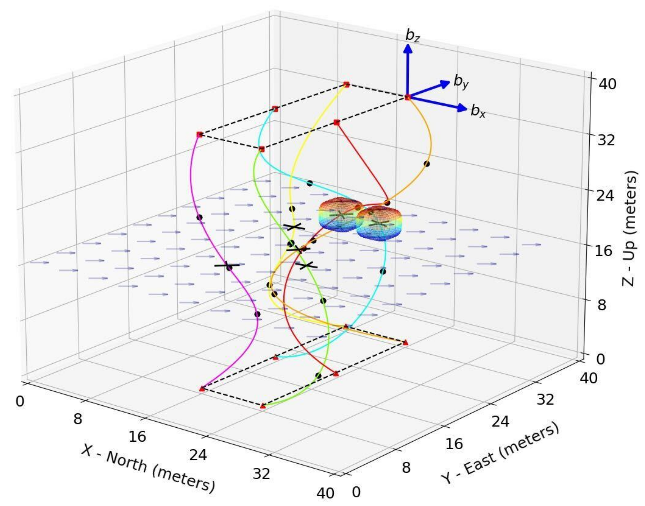
All quadrotors are required to maintain a minimum safe distance d safe to avoid collisions with each other. For each quadrotor i, the total arc length of its path is calculated using the Gaussian quadrature and is denoted by U i . The linear and angular speeds of quadrotor i along its fixed path are denoted by s i and ω i , each expressed in the body-fixed frame of the quadrotor. p i ( t ) = ( x i ( t ) , y i ( t ) , z i ( t ) ) is the location of quadrotor i in the NED frame on its path at time t, and is calculated using the speed s i ( t ) . The path for quadrotor i is represented by a 3-dimensional, piecewise 7th order spline curve SP i ( u ) , where the parameter u is the normalized arc length along the curve. The curves are obtained by combining three 1-dimensional piecewise 7th order splines. The piecewise 7th order spline curves feature continuous first derivatives (slope), second derivatives (curvature), third derivatives (jerk), and fourth derivatives (snap) along the curve. Figure 2 depicts the spline curve paths for a 6-quadrotor scenario.
The differential flatness of quadrotor dynamics, use of 3-dimensional piecewise 7th order spline curves, and the constraints on the speed, acceleration, snap, and yaw rate results in a kino-dynamically feasible speed profile for quadrotors [31,32]. A detailed discussion on spline curve design and analysis can be found in [33]. Let κ i ( u ) be the curvature along the spline curve i. The angular speed ω i ( u ) can be computed from the linear speed and spline curvature as follows:
ω i ( u ) = s i ( u ) κ i ( u ) .

2.2. Receding Horizon (RH)

T hor denotes the length of the receding horizon and is determined by the capabilities of the embedded flight planning and control system. At any discrete time step t, each quadrotor must calculate its plan for t + 1 , …, t + T hor and communicate this plan with other quadrotors in the network. This plan is denoted by P i ( t ) = ( p i ( t + 1 ) , , p i ( t + T hor ) ) . Only the plan for time t + 1 is implemented, and the planning process is restarted at time step t + 1 . At time step T mission , the mission is completed when the last-arriving quadrotor reaches its end point. If a quadrotor reaches its goal point before T mission , it hovers there until the mission is over.

2.3. Communication Modeling and Ordering

Each quadrotor is equipped with a mobile ad-hoc network (MANET) radio to exchange RH-MINLP solutions with other quadrotors. MANET communication is accomplished via direct one-hop connection or multi-hop relaying, thus resulting in a fully connected network. A round-robin scheduling technique for sequential wireless communication is used for fair distribution of MANET bandwidth and fault tolerance. The sequence of the quadrotors for the round-robin scheduling is determined randomly at the beginning of the mission. The first quadrotor in the round-robin is also the first to take off.

2.4. Dryden Wind Model and Spline Regeneration

The continuous Dryden turbulence model is used to simulate wind gusts and study their effects on the motion planning solutions [34]. We provided the first-in-literature, open-source implementation of the Dryden wind turbulence model in [35]. When the quadrotors are displaced off their pre-defined spline paths due to wind gusts, a rapid spline regeneration process ensures that each quadrotor has an updated spline path starting from the displaced location to the endpoint. Spline regeneration is effectively visualized in the accompanying video submission.

2.5. Control Barrier Functions and Safety Barrier Certificates

Each quadrotor is encapsulated in a super-ellipsoidal, Exponential Control Barrier Function (ECBF) depicted in Figure 2. For a pair of quadrotors ( i , j ) , the pairwise safe set B i j and the pairwise super ellipsoid h i j ( q i , q j ) are defined as:
B i j = { ( q i , q j ) | h i j ( q i , q j ) 0 } ,
h i j ( q i , q j ) = ( x i x j ) 4 + ( y i y j ) 4 + ( z i z j c ) 4 d s a f e 4
where q i represents the full state of the quadrotor i, d safe is the safety distance, c is the scaling factor along the Z-axis caused by airflow disturbance from the downwash of one quadrotor flying over of another quadrotor. In this study, the quadrotors flew at a safe distance from each other along the vertical direction. As such, c was chosen to be equal to one (1). The two quadrotors are considered safe when the two super-ellipsoids do not intersect. Readers are referred to [36] and its references for information about the mathematical construction, verification, and incorporation of ECBFs in motion planners through the use of Quadratic Programming (QP).

3. Optimization Model

The optimization (MINLP) problem O i ( t ) solved by each quadrotor is expressed in (4)–(14). The optimization is performed for speed s i of the quadrotor along its specified path and auxiliary variables are used for position ( x i , y i , z i ), arc length ( u i ), acceleration ( a i ), and communication connectivity ( C i j , j i ). Each quadrotor i uses the most current plans of all other quadrotors while solving O i ( t ) .
Problem Size:
O ( t ) has ( n + 5 ) T hor decision variables, ( 2 n + 5 ) T hor constraints, and variables bounds. The problem size grows linearly with the number of quadrotors n.

3.1. Objective Function

The objective function (4) forces the quadrotors to minimize the total distance (arc length) between their current location and the goal position over the entire receding horizon. It prioritizes the quadrotors’ movement to their goal positions.
minimize s , x , y , z , u , a , C k = t + 1 t + T h o r ( U i u i ( k ) ) subject   to k { t + 1 , , T hor }
( x i ( k ) , y i ( k ) , z i ( k ) ) = SP i ( u i ( k ) )
u i ( k ) = u i ( k 1 ) + s i ( k ) Δ t
u i ( t ) u i ( k ) U i
s i ( k ) = s i ( k 1 ) + a i ( k ) Δ t
s min s i ( k ) s max
a min a i ( k ) a max j { 1 , , n } , j i
d i j ( k ) 2 d safe 2
d i j ( k ) 2 M ( 1 C i j ( k ) ) + η d 2
j : j i C i j ( k ) n conn
C i j ( k ) { 0 , 1 }

3.2. Path (Kinematic) Constraints

Constraints (5)–(7) define the quadrotor’s location along its path. Location can be defined in two ways: arc length traversed along the quadrotor’s path ( u i ) and the coordinates of its location ( x i , y i , z i ). The former is used to define kinematic and dynamic constraints, while the latter is used to calculate Euclidean distances between quadrotors for collision avoidance and communication connectivity. Constraint (5) defines the 7th order spline curves SP i ( u i ( k ) ) that link these two sets of variables. Given its location at the beginning of the planning period, constraint (6) increments the arc length at each time step based on the speed of the quadrotor. Δ t is the DJI Matrice M100’s flight controller update rate obtained directly during actual tests. Constraint (7) ensures that the quadrotor will remain between its location at the beginning of the planning period and its goal position at all times.

3.3. Speed and Acceleration (Dynamic) Constraint

Given the quadrotor’s linear speed s i at the beginning of the planning period, constraint (8) increments the speed at each time step based on its acceleration a i . Constraints (9)–(10) are dynamic constraints that ensure that the linear speed (and hence, the angular speed) and acceleration for each quadrotor at each time step are sufficiently bounded. The bounds are determined by the capabilities of the DJI M100 quadrotor and the curvature of the spline paths to ensure that the quadrotor motors do not saturate. Since the 7th order spline curves are generated while minimizing snap (4th derivative), the paths allow for smooth trajectory following. The angular speed required by the quadrotors corresponding to the optimal linear speed is always achievable and is determined using a relationship (1).

3.4. Collision Avoidance Constraint

The non-convex constraint (11) defines the required minimum distance d safe between each pair of quadrotors at all times to avoid collisions.

3.5. Communication Connectivity Constraint

The binary variable C i j ( t ) indicates whether two quadrotors are in one-hop communication range η d of each other, as shown in the following equation:
C i j ( t ) = 1 , if d i j η d , 0 , otherwise .

4. Optimization Solution Technique

The numerical optimization solution technique for solving (4)–(14) is divided into three levels—the outer level, the middle level, and the lower level.
Since there are multiple decision makers (i.e., multiple quads), the outer level establishes the initial conditions of multi-quad distributed decision making in terms of decision ordering and associated motion plan data at each time step t.
The middle and lower levels are rooted in well-established numerical optimization solution approaches for solving mixed integer nonlinear programming (MINLP) problems [37,38]. In the middle level, the algorithm handles the discrete variables and communication constraints of each quadrotor’s problem O i ( t ) via Simulated Annealing (SA). The SA approach establishes the discrete variable, thus turning the rest of the optimization problem into a continuous nonlinear programming problem. This underlying continuous nonlinear programming problem is solved in the lower level using interior-point methods to determine each quadrotor’s speed during the time horizon.

4.1. Outer Level: Distributed Decision Making

All quadrotors are in the communication range of each other at time 0. As discussed, a round-robin decision-making and communication order is enforced among quadrotors. The ordering can be randomly assigned or can be assigned a priori. It is assumed without loss of generality that the ordering is represented as 1 , , n .
Each quadrotor i sequentially solves the problem O i ( t + 1 ) at time t by taking into account the following plans:
  • Plans P j ( t + 1 ) for quadrotors j < i , as these quadrotors have already calculated their new plans, and 
  • Plans P j ( t ) for quadrotors j > i , as these quadrotors have yet to calculate their new plans.
If O i ( t + 1 ) is feasible, the new plan becomes P i ( t + 1 ) . If it is infeasible, then the quadrotors simply hover in place for safety till an operator takes over. Each plan is then communicated to the rest of the quadrotors.

4.2. Middle Level: Simulated Annealing for Discrete Variables and Communication Constraints

The outer level requires the solution of O i ( t + 1 ) for each quadrotor i at each time step t. The communication variables and the connectivity constraints (12) contribute significantly to the computational complexity of O i ( t + 1 ) : the communication variables are binary, there are n T hor of them in each instance (the remaining variables do not change by fleet size), and there are n T hor communication constraints at each instance. As the problem size scales in n, these Big-M communication constraints that include integers and the parameter M introduce non-trivial computational effort in finding a feasible solution [39]. The middle level of the numerical solution process tackles this computational burden to generate real-time solutions.
When deciding upon an appropriate method to handle the communication variables and constraints, it should be first noted that a feasible solution to O i ( t + 1 ) is implementable, even if it is not optimal. From a solution approach perspective, a well-established method such as branch-and-bound (BB) with deep dives can be used to solve MINLPs [40,41], but this may still require the solution of multiple instances of the RH-MINLP (and hence more computational effort/time) before identifying a feasible solution, especially as the problem size grows.
By contrast, Simulated Annealing (SA) [42] is a stochastic method to quickly identify effective feasible solutions for MINLPs [43,44]. The sampling approach for neighbors of an incumbent and solution quality evaluation are critical to SA. At each iteration of SA, we sample a small number of neighbors of the current solution (also known as an “incumbent”). Any neighbor can replace the incumbent with probability 1 if it is better than the incumbent or with probability e x p Δ / T e m p if it is worse than the incumbent, where Δ measures the change in solution quality and T e m p is the current temperature of the system. T e m p is reduced at every iteration of SA, which promotes localization around a good incumbent in the later iterations. The heuristic is stopped when T e m p is sufficiently small or when a time limit is reached.
Sampling Neighbors Approach:
As described in Algorithm 1, the binary values for the communication variables were chosen to attain or promote feasibility of the solution. The condition C i j = 0 does not always imply that quadrotor i and j are not within communication distance. This condition indicates that the quadrotors do not need to be within communication distance. The incumbent solutions which satisfy the n conn constraint with equality indicate that the quadrotors are required to maintain at least n conn , and not exactly n conn . This method for generating a neighbor of the incumbent solution for N waypoints is depicted in Algorithm 1.
Algorithm 1 Generating a neighbor of an incumbent solution for Simulated Annealing
1:
Input: The sets { 1 , , N 1 } and { 1 , , T h o r } , C k
2:
Output: C k
3:
Randomly select k { 1 , , T h o r } .
4:
Randomly select j C k and j C k .
5:
Set C i j ( k ) = 0 , C i j ( k ) = 1 .
6:
Update: C k C k \ j j .
Evaluating Solution Quality: Once the communication variables are fixed and constraint (13) satisfied, a reduced form of O i ( t ) , denoted by O reduced i ( t ) , is created where constraints (12)–(14) are replaced by
d i j ( k ) 2 η d 2 if C i j ( k ) = 1
The objective function value of O reduced i ( t ) is used as the metric of solution quality by SA (chosen as for an infeasible instance).
Moreover, O reduced i ( t ) features a reduction in the computational burden as n increases when compared to (4)–(14) due to the lack of big-M constraints and integer variables.
Reduced Problem Size: The resulting optimization problem is also significantly smaller in size, with 5 T hor variables and ( N + n c o n n + 4 ) T hor constraints.

4.3. Lower Level: Nonlinear Optimization

O reduced i ( t ) is a non-linear, non-convex program and can be solved using an interior-point method for nonlinear optimization adapted from [45]. Readers are referred to [45] and its references for further details on this nonlinear optimization technique.

5. Experimental Setup and Results

The RH-MINLP framework was implemented in numerical simulations, HWIL, and outdoor flight tests. The optimization model O i , optimization solver (all three levels), and CBFs were implemented in Python 3.7. Custom spline generation functions implemented in Python were used to generate the minimum snap 7th order splines passing through N pre-selected waypoints. The Dryden Model to generate wind gusts was also implemented on the ground station computer in Python.
Numerical simulations were carried out using a desktop computer fitted with an Lenovo i5-6400 Intel CPU 2.70 GHz Quad-core processor and 8 GB RAM. HWIL and outdoor flight tests were conducted with DJI M100 quadrotors fitted with a Raspberry Pi 4 (Quad-core Cortex-A72 (ARM v8) 64-bit SoC @ 1.5 GHz and 4 GB RAM) computer. Each quadrotor was fitted with a transceiver radio module operating in the 915 MHz license-free frequency bands, providing half-duplex bi-directional RF links at 300 Kbps. A ground station computer (Lenovo Intel Dual Core i5 @ 3.3 GHz Processor and 8 GB RAM) was part of the MANET and hosted a web-based user interface for mission configuration, clock synchronization, and mission upload. The GPS sensor’s positional accuracy and sampling rate onboard the DJI M100 are 1 m (average) and 4 Hz, respectively. The fused telemetry stream data from the DJI M100 were sampled at 50 Hz to obtain state feedback (real-time locations and speeds). The quadrotors were equipped with the TB48D battery that has a capacity of 5700 mAh [46]. Table 1 lists key motion and communications parameters used in HWIL, numerical simulations, and field tests.
The HWIL tests were executed using the DJI Assistant 2 flight simulation software. The software provided real-time emulation of the telemetry outputs and velocity yaw rate inputs to the DJI N1 flight controller based on the rigid body dynamics of the DJI M100. During HWIL testing, the quadrotors and ground station were placed in line with approximately 0.5 m between each quadrotor and approximately 1.5-m separation from the ground station.
The Python implementation interfaced with DJI M100 real-time telemetry data via UART and a Linux SDK provided by the DJI M100 N1 flight computer. The speed obtained by solving the O served as the set-point for the DJI M100’s N1 flight controller, which exerted the appropriate control effort to achieve the set-point. During outdoor tests, a manual override was implemented to stall the quadrotor in place until a human operator took over in case of degraded MANET performance (average inter-quadrotor wireless latency greater than 0.33 s), heavy wind gusts (>18 m/s mean value), or critically low battery in the quadrotors (<5% battery power).
Numerical simulations focused on exploring scalability (up to 50 quadrotors) of the RH-MINLP + CBF framework and comparing the computational efficiency of the SA + Interior Point Method solver with another established method (Branch-and-Bound (BB) + Interior Point Method). HWIL tests were performed with up to 6 DJI M100 to study (1) the effect of wind disturbances on safety violations, (2) the safety accorded by CBFs, and (3) the effect of wind disturbances and CBFs on T mission . Actual flight tests followed the simulations and HWIL tests in outdoor, windy settings to validate the real-time feasibility of the RH-MINLP + CBF approach.
Each flight in numerical simulations, HWIL tests, and outdoor tests was conducted in a 40 m × 40 m × 20 m airspace and consisted of the following three sub-tasks:
  • Take-off and Formation: The quadrotors would take off one at a time and move to a preset location to organize themselves in a geometric formation. Example initial formations included a straight line, triangle, and rectangle as shown in Figure 1. The initial height of the formation was 12.5 m above ground level (AGL).
  • Waypoint-based Transit: Once in formation, the quadrotors would start their transit while maintaining their flight formation, to the extent possible, and visit a total of 5 waypoints spread out across an area of 40 m × 40 m × 20 m.
  • Return-To-Home (RTH): Once the quadrotors visited all the waypoints, they sequentially executed an RTH procedure to land at their take-off locations safely.
Key evaluation metrics are defined as:
  • T mission : denotes the transit time between the start of the multiple quadrotor formation and their return to their start points averaged over multiple runs.
  • n CBF : number of CBF activations averaged over multiple runs and rounded to the nearest integer.
  • T comp : Solver computation time averaged over all quadrotors, further averaged over multiple runs.
  • RR: Optimization based motion-plan re-planning rate in Hz, average over multiple runs.
  • T saving : denotes the percentage of T comp time saved when using SA instead of the BB method.
  • D obj - gap : denotes the percentage gap in the objective function values (as defined by (4)) between BB and SA.
Each numerical simulation was repeated five (5) times, HWIL experiments were repeated nine (9) times, and outdoor flight tests were conducted five (5) times. Dryden gusts with average 9 m/s speed and standard deviation of 1.23 m/s were used in numerical simulations and HWIL.

5.1. HWIL: Flight Safety Accorded by CBFs

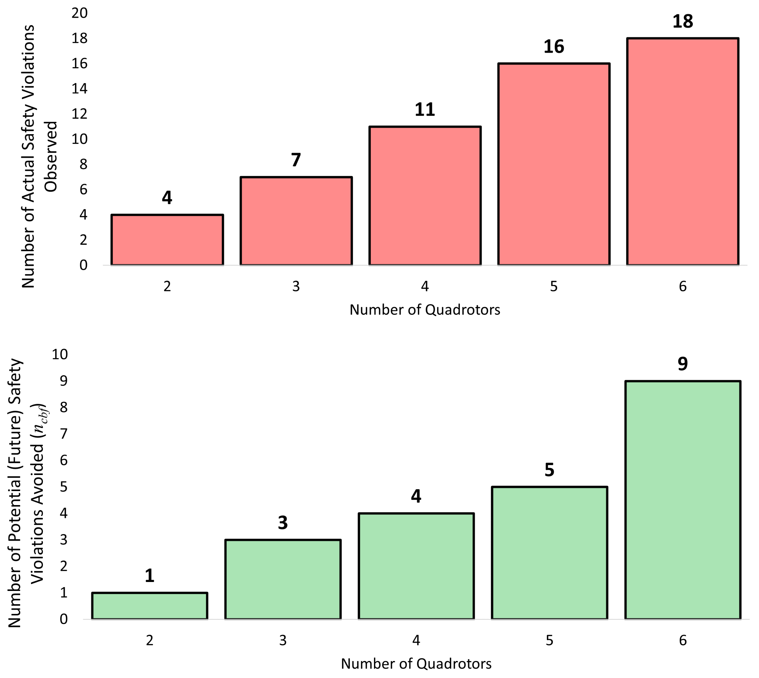
For a fixed d safe , Figure 3 (top) depicts the number of times the inter-quadrotor distance ( d i j ) was less than d safe during windy conditions. These actual safety violations were observed because the wind gusts disturbed the quadrotors off their planned course despite recalculating O . This observation underscores the need for additional safeguards to prevent in-flight collisions.
Once CBFs were added to the motion-planning process, as depicted in Figure 3 (bottom), there were zero (0) actual safety violations during flight despite windy conditions, i.e., several potential safety violations (in the future) were avoided due to CBF activations.
Also, the number of potential safety violations (in the future) that were prevented by adding the CBFs were significantly less than the case when no CBFs were present. This is due to the fact that the quadrotors were moving in a safer fashion from the very beginning of their mission due to the activation of the CBFs. Hence, there was a relatively lower number of potential safety violations in future time steps. We note that in the absence of Dryden wind gusts, no safety violations were observed while solving O .

5.2. HWIL: Effect of Wind Disturbances and CBFs on T m i s s i o n

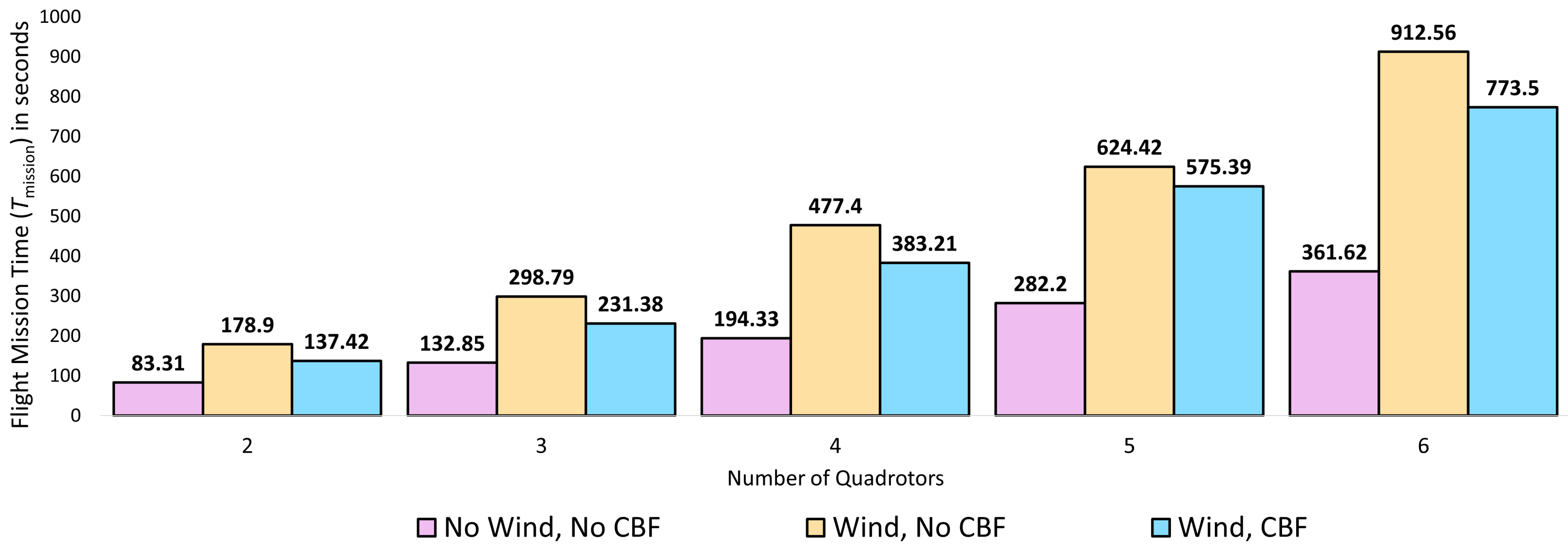
For a fixed d safe , Figure 4 depicts the change in T mission in the absence and presence of wind disturbances. It is observed that T mission increases significantly in the presence of the Dryden wind gusts because O is solved more often (the wind gusts cause the quadrotors to move off-course).
Figure 4 also depicts the change in T mission in the presence of wind disturbances while using CBFs (blue-colored data series). It is observed that the T mission increases with CBFs in windy conditions as compared to the no wind case. However, it is also observed that in the presence of CBFs, T mission is lower than the T mission when no CBFs are present. This is due to the fact that the CBF activations afford collision-avoidance from the very beginning of the mission thereby reducing the number of times O needs to be resolved. A reduced T mission also led to lower use of quadrotor battery. Averaged over the 9 runs, the battery savings per quadrotor in the case of the 2, 3, 4, 5, and 6 quadrotor test were 25.14 % , 20.39 % , 18.52 % , 11.81 % , and 16.4 % , respectively.

5.3. Numerical Simulations for Scalability

Numerical simulations were performed for up to 50 quadrotors operating outdoors to study computational scalability in the presence of Dryden wind gusts. Table 2 notes results for each of these scenarios. The SA + interior-point numerical solution method was compared with a BB + interior point method as presented in [40,41].
As is observed, for all cases, n CBF , and T comp increase with n. The increase is pronounced at higher n due to increased collision possibilities and an increase in the number of variables and constraints for O .
It is observed that SA outperforms BB in terms of T comp as indicated by T saving . These T comp savings can be attributed to the fact that BB fixes a subset of the binary variables (and leaves the rest as continuous, between 0 and 1) at any iteration which in turn, causes the nonlinear solver to face larger problems with BB than with SA. However, when it concludes, BB yields superior objective function values for all tests except in the case of n = 20 , which is expected since it focuses on global optimality. As the number of quadrotors is scaled up, BB may not conclude in real-time, either due to the size of the problem or the nonconvexity of the underlying nonlinear problem due to the collision avoidance constraints. On the other hand, SA is a search heuristic that focuses first on attaining feasibility and then on further improving the objective function value, and can be stopped within the real-time requirements.

5.4. Outdoor Flight Tests

Outdoor field tests were conducted with up to 6 DJI M100 quadrotors to validate the RH-MINLP + CBF framework. The test was conducted in an open field at a park in Philadelphia. The wind disturbances during the flight tests were measured using an FT205 ultrasonic anemometer mounted on a DJI M100 quadrotor using a 20-inch long 3D printed pole as shown in Figure 1. The FT205 was sampled at a frequency of 2 Hz. The wind measurements were performed with the quadrotor hovering at a height of 12.5 m above ground level. The quadrotor was flown approximately 50 m away from the multi-quadrotor system to maintain safety. During the field test with 2 quadrotors, the mean wind speed was 12.23 m/s with a standard deviation 3.49 m/s. During the field test with 3 quadrotors, the mean wind speed was 10.33 m/s with a standard deviation 1.54 m/s. During the field test with 6 quadrotors, the mean wind speed was 13.5 m/s with a standard deviation 2.0 m/s.
Figure 1 depicts a snapshot of a 2, 3, and 6-quadrotor tests. Table 3 depicts the average T mission , n CBF , T comp , and re-planning rate (RR). T comp varied from 26.8 ms to 74.6 ms. Re-planning rates varied between 12 Hz to 30 Hz.
Readers are referred to the accompanying video for footage of the flight tests. For the 2-quadrotor test, a CBF was activated when the quadrotors completed a concentric-spiral path mission and the two quadrotors were about to breach the safety distance threshold. One of the quadrotors came to a hover, allowing the other quadrotor to pass. Similarly, for the 3-quadrotor test, the CBF was activated twice, once each between two different pairs. For the 6-quadrotor test, 4 CBFs were activated between different pairs when the quadrotors came close to each other due to wind gusts.

6. Discussion

  • Due to the inherent distributed nature of the decision making, certain quadrotors’ decisions may render the coordination problem difficult or infeasible to solve for other quadrotors. In some cases, reassigning a different decision order helped improve overall solutions. Safety is always maintained since the quadrotors can hover in place in case of infeasibility.
  • Even when CBFs are used to provide an additional layer of assistance in collision avoidance, guaranteeing robustness to collisions is non-trivial because of the non-linearities in the multi-UAV system and unknown wind disturbances. Future work will explore the study of robust control barrier functions for constrained stabilization of the multi-UAV system, as noted in [27].
  • While rare, satisfying the communication constraint can still result in network partitions. Strategies to mitigate such unusual circumstances have been developed and presented in [47].
  • As observed in Figure 4, as the number of quadrotors increase, the difference between T mission without CBFs and T mission with CBFs decreases. The effectiveness of CBFs in multi-robot systems at scale is an open area of research and will be investigated in future work [48].

7. Conclusions

This work validated a distributed, RH-MINLP + CBF-based motion planner for multiple quadrotors operating in windy outdoor environments. The validation was performed via numerical simulations, HWIL, and outdoor flight tests. A novel 3-level optimization solver that used Simulated Annealing was developed to expedite the optimization solution process resulting in feasible online motion-planning. The Dryden wind gust model provided realistic wind effects during the simulations and HWIL experiments. The use of CBFs provided protection against safety violations and potential mid-flight collisions that could have resulted due to the wind disturbances, in turn reducing mission times. The simulation and experiment results demonstrated the computational time savings accorded by the SA-based numerical solution process when compared to a well-established method, thus demonstrating the scalability of this framework. Future work will focus on incorporating online estimates of wind gusts in the planning using a non-sequential MANET communication techniques, and approaches to improve the sampling in Algorithm 1 based on current distances and past plans.

Author Contributions

Conceptualization, P.A. and D.L.; methodology, P.A. and D.L.; software, D.L., M.M., W.M. and N.R.; validation, W.M., P.A. and D.L.; formal analysis, P.A. and D.L.; investigation, D.L., P.A. and H.B.; resources, P.A., W.M. and D.B.; data curation, W.M. and N.R.; writing—original draft preparation, D.L. and P.A.; writing—review and editing, P.A. and D.L.; visualization, D.L. and P.A.; supervision, P.A.; project administration, P.A. All authors have read and agreed to the published version of the manuscript.

Funding

Funding for this work came from Lockheed Martin Advanced Technology Laboratories, Drexel University, and the New Jersey Institute of Technology through multiple internal research and development (IRAD) grants.

Data Availability Statement

Source code has been made available at https://github.com/radlab-sketch/ (accessed on 24 December 2022).

Conflicts of Interest

The authors declare no conflict of interest.

References

  1. Causa, F.; Franzone, A.; Fasano, G. Strategic and Tactical Path Planning for Urban Air Mobility: Overview and Application to Real-World Use Cases. Drones 2023, 7, 11. [Google Scholar] [CrossRef]
  2. Schouwenaars, T.; De Moor, B.; Feron, E.; How, J. Mixed integer programming for multi-vehicle path planning. In Proceedings of the 2001 European Control Conference (ECC), Porto, Portugal, 4–7 September 2001; pp. 2603–2608. [Google Scholar]
  3. Richards, A.; How, J.P. Aircraft trajectory planning with collision avoidance using mixed integer linear programming. In Proceedings of the 2002 American Control Conference (IEEE Cat. No.CH37301), Anchorage, AK, USA, 7 November 2002; Volume 3, pp. 1936–1941. [Google Scholar]
  4. Rezende, A.M.; Goncalves, V.M.; Pimenta, L.C. Safe coordination of robots in cyclic paths. ISA Trans. 2021, 109, 126–140. [Google Scholar] [CrossRef] [PubMed]
  5. Luo, Y.; Lu, J.; Zhang, Y.; Zheng, K.; Qin, Q.; He, L.; Liu, Y. Near-Ground Delivery Drones Path Planning Design Based on BOA-TSAR Algorithm. Drones 2022, 6, 393. [Google Scholar] [CrossRef]
  6. Abichandani, P.; Torabi, S.; Basu, S.; Benson, H.Y. Mixed Integer Nonlinear Programming Framework for Fixed Path Coordination of Multiple Underwater Vehicles Under Acoustic Communication Constraints. IEEE J. Ocean. Eng. 2015, 40, 864–873. [Google Scholar] [CrossRef]
  7. Wang, T.; Lima, R.M.; Giraldi, L.; Knio, O.M. Trajectory planning for autonomous underwater vehicles in the presence of obstacles and a nonlinear flow field using mixed integer nonlinear programming. Comput. Oper. Res. 2019, 101, 55–75. [Google Scholar] [CrossRef] [Green Version]
  8. Shi, W.; Li, J.; Cheng, N.; Lyu, F.; Zhang, S.; Zhou, H.; Shen, X. Multi-drone 3-D trajectory planning and scheduling in drone-assisted radio access networks. IEEE Trans. Veh. Technol. 2019, 68, 8145–8158. [Google Scholar] [CrossRef] [Green Version]
  9. Zhao, S.; Wang, X.; Chen, H.; Wang, Y. Cooperative path following control of fixed-wing unmanned aerial vehicles with collision avoidance. J. Intell. Robot. Syst. 2020, 100, 1569–1581. [Google Scholar] [CrossRef]
  10. Ragi, S.; Mittelmann, H.D. Mixed-integer nonlinear programming formulation of a UAV path optimization problem. In Proceedings of the 2017 American Control Conference (ACC), Seattle, WA, USA, 24–26 May 2017; pp. 406–411. [Google Scholar]
  11. Abichandani, P.; Levin, K.; Bucci, D. Decentralized Formation Coordination of Multiple Quadcopters under Communication Constraints. In Proceedings of the 2019 International Conference on Robotics and Automation (ICRA), Montreal, QC, Canada, 20–24 May 2019; pp. 3326–3332. [Google Scholar]
  12. Kuwata, Y.; Schouwenaars, T.; Richards, A.; How, J. Robust constrained receding horizon control for trajectory planning. In Proceedings of the AIAA Guidance, Navigation, and Control Conference and Exhibit, San Francisco, CA, USA, 15–18 August 2005; p. 6079. [Google Scholar]
  13. Chiang, W.C.; Li, Y.; Shang, J.; Urban, T.L. Impact of drone delivery on sustainability and cost: Realizing the UAV potential through vehicle routing optimization. Appl. Energy 2019, 242, 1164–1175. [Google Scholar] [CrossRef]
  14. Cho, D.H.; Ha, J.S.; Lee, S.; Moon, S.; Choi, H.L. Informative path planning and mapping with multiple UAVs in wind fields. In Distributed Autonomous Robotic Systems; Springer: Berlin/Heidelberg, Germany, 2018; pp. 269–283. [Google Scholar]
  15. Thibbotuwawa, A.; Bocewicz, G.; Radzki, G.; Nielsen, P.; Banaszak, Z. UAV Mission Planning Resistant to Weather Uncertainty. Sensors 2020, 20, 515. [Google Scholar] [CrossRef] [Green Version]
  16. Patrikar, J.; Dugar, V.; Arcot, V.; Scherer, S. Real-time Motion Planning of Curvature Continuous Trajectories for Urban UAV Operations in Wind. In Proceedings of the 2020 International Conference on Unmanned Aircraft Systems (ICUAS), Athens, Greece, 1–4 September 2020; pp. 854–861. [Google Scholar]
  17. Jarray, R.; Bouallègue, S.; Rezk, H.; Al-Dhaifallah, M. Parallel Multiobjective Multiverse Optimizer for Path Planning of Unmanned Aerial Vehicles in a Dynamic Environment with Moving Obstacles. Drones 2022, 6, 385. [Google Scholar] [CrossRef]
  18. Military Standard. Flying Qualities of Piloted Aircraft; Technical Report MIL-STD-1797A; US Department of Defense: Fort Belvoir, VA, USA, 1990.
  19. Moorhouse, D.J.; Woodcock, R.J. Background Information and User Guide for MIL-F-8785C, Military Specification-Flying Qualities of Piloted Airplanes; Technical Report AFWAL-TR-81-3109; Air Force Wright Aeronautical Labs, Wright-Patterson Air Force Base: Dayton, OH, USA, 1982. [Google Scholar]
  20. Rodriguez, L.; Cobano, J.A.; Ollero, A. Wind field estimation and identification having shear wind and discrete gusts features with a small UAS. In Proceedings of the 2016 IEEE/RSJ International Conference on Intelligent Robots and Systems (IROS), Daejeon, Republic of Korea, 9–14 October 2016; pp. 5638–5644. [Google Scholar]
  21. Abichandani, P.; Lobo, D.; Ford, G.; Bucci, D.; Kam, M. Wind Measurement and Simulation Techniques in Multi-Rotor Small Unmanned Aerial Vehicles. IEEE Access 2020, 8, 54910–54927. [Google Scholar] [CrossRef]
  22. Ames, A.D.; Coogan, S.; Egerstedt, M.; Notomista, G.; Sreenath, K.; Tabuada, P. Control Barrier Functions: Theory and Applications. In Proceedings of the 2019 18th European Control Conference (ECC), Naples, Italy, 25–28 June 2019; pp. 3420–3431. [Google Scholar]
  23. Ghaffari, A. Operational Safety Control for Unmanned Aerial Vehicles Using Modular Barrier Functions. In Proceedings of the 2020 American Control Conference (ACC), Denver, CO, USA, 1–3 July 2020; pp. 1719–1724. [Google Scholar]
  24. Xu, B.; Sreenath, K. Safe teleoperation of dynamic UAVs through control barrier functions. In Proceedings of the 2018 IEEE International Conference on Robotics and Automation (ICRA), Brisbane, Australia, 13 September 2018; pp. 7848–7855. [Google Scholar]
  25. Lindemann, L.; Dimarogonas, D.V. Control barrier functions for multi-agent systems under conflicting local signal temporal logic tasks. IEEE Control Syst. Lett. 2019, 3, 757–762. [Google Scholar] [CrossRef]
  26. Robey, A.; Hu, H.; Lindemann, L.; Zhang, H.; Dimarogonas, D.V.; Tu, S.; Matni, N. Learning control barrier functions from expert demonstrations. In Proceedings of the 2020 59th IEEE Conference on Decision and Control (CDC), Jeju, Republic of Korea, 14–18 December 2020; pp. 3717–3724. [Google Scholar]
  27. Jankovic, M. Robust control barrier functions for constrained stabilization of nonlinear systems. Automatica 2018, 96, 359–367. [Google Scholar] [CrossRef]
  28. Israr, A.; Ali, Z.A.; Alkhammash, E.H.; Jussila, J.J. Optimization Methods Applied to Motion Planning of Unmanned Aerial Vehicles: A Review. Drones 2022, 6, 126. [Google Scholar] [CrossRef]
  29. Abichandani, P.; Mallory, K.; Hsieh, M.y.A. Experimental multi-vehicle path coordination under communication connectivity constraints. In Experimental Robotics; Springer Tracts in Advanced Robotics Book Series; Springer: Berlin/Heidelberg, Germany, 2013; pp. 183–197. [Google Scholar]
  30. Abichandani, P.; Ford, G.; Benson, H.Y.; Kam, M. Mathematical programming for multi-vehicle motion planning problems. In Proceedings of the 2012 IEEE International Conference on Robotics and Automation, Saint Paul, MN, USA, 14–18 May 2012; pp. 3315–3322. [Google Scholar]
  31. Mellinger, D.; Kumar, V. Minimum snap trajectory generation and control for quadrotors. In Proceedings of the 2011 IEEE International Conference on Robotics and Automation, Shanghai, China, 9–13 May 2011; pp. 2520–2525. [Google Scholar]
  32. Richter, C.; Bry, A.; Roy, N. Polynomial trajectory planning for aggressive quadrotor flight in dense indoor environments. In Robotics Research; Springer: Berlin/Heidelberg, Germany, 2016; pp. 649–666. [Google Scholar]
  33. Lepetic, M.; Klancar, G.; Skrjanc, I.; Matko, D.; Potocnik, B. Time optimal path planning considering acceleration limits. Robot. Auton. Syst. 2003, 45, 199–210. [Google Scholar] [CrossRef]
  34. Hakim, T.M.I.; Arifianto, O. Implementation of Dryden Continuous Turbulence Model into Simulink for LSA-02 Flight Test Simulation. J. Phys. Conf. Ser. 2018, 1005, 012017. [Google Scholar] [CrossRef]
  35. Lobo, D. Implementation of Dryden Wind Turbulence Model in Python, 2020, Source Code. Available online: https://github.com/radlab-sketch/drydenModelPython (accessed on 24 December 2022).
  36. Wang, L.; Ames, A.D.; Egerstedt, M. Safe certificate-based maneuvers for teams of quadrotors using differential flatness. In Proceedings of the 2017 IEEE International Conference on Robotics and Automation (ICRA), Singapore, 29 May–3 June 2017; pp. 3293–3298. [Google Scholar]
  37. Potra, F.A.; Wright, S.J. Interior-point methods. J. Comput. Appl. Math. 2000, 124, 281–302. [Google Scholar] [CrossRef] [Green Version]
  38. Benson, H.Y.; Shanno, D.F. Interior-Point Methods for Nonconvex Nonlinear Programming: Regularization and Warmstarts. Comput. Optim. Appl. 2008, 40, 143–189. [Google Scholar] [CrossRef]
  39. Bonami, P.; Lodi, A.; Tramontani, A.; Wiese, S. On mathematical programming with indicator constraints. Math. Program. 2015, 151, 191–223. [Google Scholar] [CrossRef]
  40. Lee, J.; Leyffer, S. Mixed Integer Nonlinear Programming; Springer Science & Business Media: Berlin/Heidelberg, Germany, 2011; Volume 154. [Google Scholar]
  41. Liberti, L.; Sager, S.; Wiegele, A. Mixed-integer Nonlinear Optimization: A hatchery for modern mathematics. Oberwolfach Rep. 2020, 16, 1573–1637. [Google Scholar] [CrossRef]
  42. Kirkpatrick, S.; Gelatt, C.D., Jr.; Vecchi, M.P. Optimization by simulated annealing. Science 1983, 220, 671–680. [Google Scholar] [CrossRef] [PubMed]
  43. Cardoso, M.; Salcedo, R.; De Azevedo, S.F.; Barbosa, D. A simulated annealing approach to the solution of MINLP problems. Comput. Chem. Eng. 1997, 21, 1349–1364. [Google Scholar] [CrossRef]
  44. Wei-zhong, A.; Xi-Gang, Y. A simulated annealing-based approach to the optimal synthesis of heat-integrated distillation sequences. Comput. Chem. Eng. 2009, 33, 199–212. [Google Scholar] [CrossRef]
  45. Shanno, D.; Vanderbei, R. Interior-Point Methods for Nonconvex Nonlinear Programming: Orderings and Higher-Order Methods. Math. Prog. 2000, 87, 303–316. [Google Scholar] [CrossRef]
  46. Matrice 100 TB48D Battery. Available online: https://store.dji.com/product/matrice-100-tb48d-battery (accessed on 5 January 2023).
  47. Abichandani, P.; Benson, H.Y.; Kam, M. Multi-vehicle path coordination in support of communication. In Proceedings of the 2009 IEEE International Conference on Robotics and Automation, Kobe, Japan, 12–17 May 2009; pp. 3237–3244. [Google Scholar]
  48. Qin, Z.; Zhang, K.; Chen, Y.; Chen, J.; Fan, C. Learning Safe Multi-agent Control with Decentralized Neural Barrier Certificates. arXiv 2021, arXiv:2101.05436. [Google Scholar]
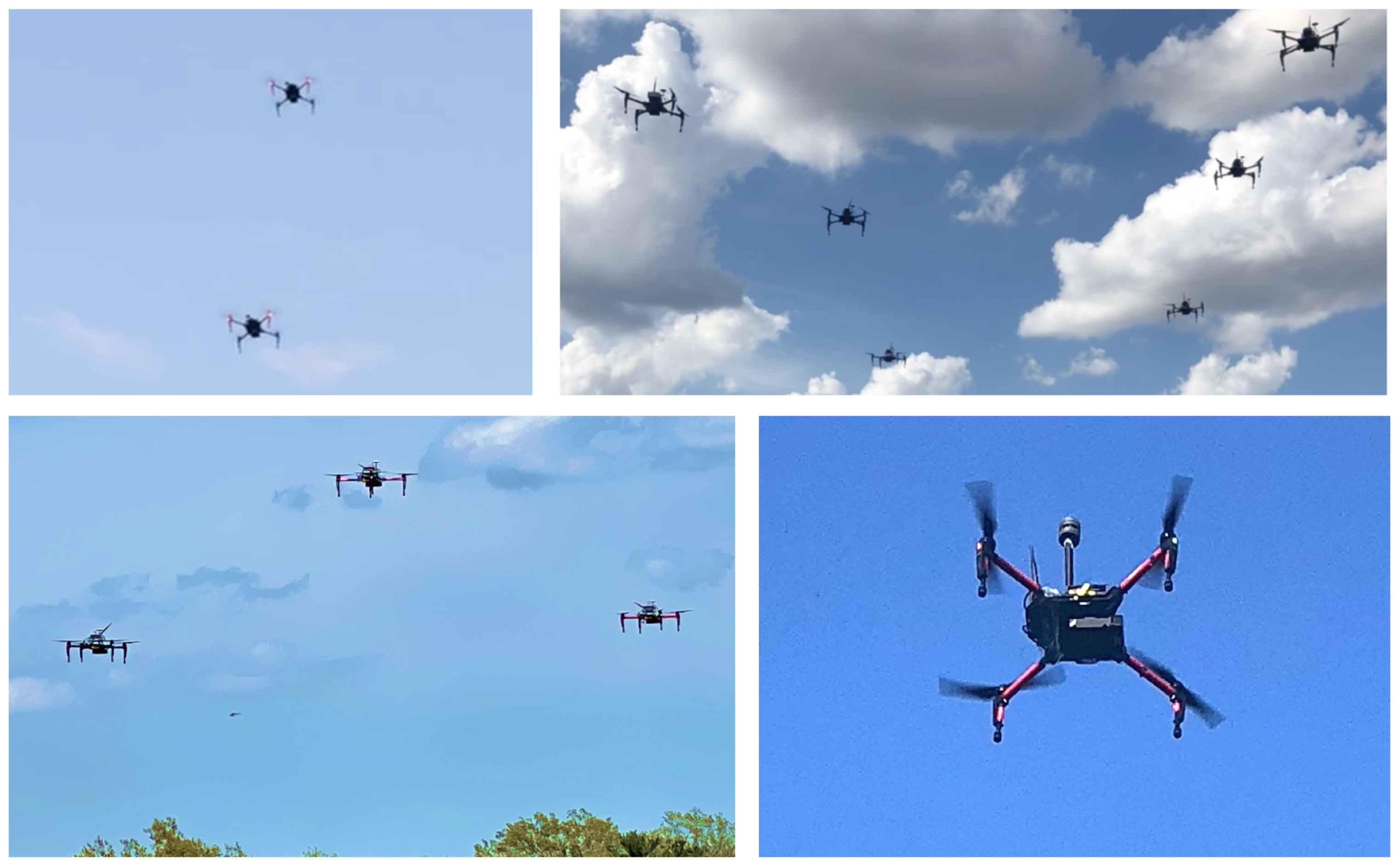
Figure 1. Snapshots of quadrotors flying in different flight formations namely straight line (2 quadrotors—top left), rectangle (6 quadrotors—top right), and triangle (3 quadrotors—bottom left). The bottom right image shows an FT-205 wind sensor mounted on the DJI Matrice 100 quadrotor to collect real-time wind data during flight test.
Drones 07 00058 g001
Figure 2. A multi-quadrotor mission with six quadrotors moving along their spline paths (represented by solid, colored lines) in the presence of wind. Control Barrier Functions (CBFs) and associated safety certificates visualized as super-ellipsoids assisted in collision avoidance in the face of wind disturbances during transit. The vector field (blue arrows) indicates spatially varying wind gusts generated using the Dryden wind model at an altitude of 15 m. Red triangular and square markers indicate the start and endpoints of the spline paths arranged in a geometric formation. Black round markers indicate spline-path waypoints. The inertial reference frame and the body frame (b x , b y , and b z ) are shown. The quadrotors are depicted here operating in a 40 m × 40 m × 40 m airspace.
Drones 07 00058 g002
Figure 3. (Top) In HWIL tests without CBF, the number of actual safety violations is shown in the red bars. As CBFs were not used, none of these actual safey violations could be avoided. (Bottom) In HWIL tests with CBF, the number of CBF-activations n CBF are shown in the green bars. Each of these CBF activations helped the quadrotors to avoid potential future safety violations. As such, the use of CBFs resulted in zero actual safety violations. Data averaged over nine runs.
Drones 07 00058 g003
Figure 4. For d safe = 3 m, the above charts depict T mission in seconds for different HWIL scenarios. The presence of wind increases the computational times and results in severe safety violations. Adding CBFs to the overall motion planning strategy reduces the overall computational times while resulting in zero safety violations. Data averaged over nine runs.
Drones 07 00058 g004
Table 1. Motion and Communication Parameters used in HWIL, numerical Simulations, and field tests.
d safe 3 m s min 0 s max 0.5 m/s
a m i n −0.25 m/s 2 a max 0.25 m/s 2 n c o n n 1
η d 5 m P t r 100 mW T hor 3
Table 2. Numerical simulation results to study scalability of the RH-MINLP framework. Data averaged over 5 runs.
nSABB
T comp n CBF T comp n CBF T saving D obj - gap
10132.314195.21647.54%−5.29%
15186.817311.91966.97%−4.66%
20271.119648.518139.21%0.2%
25383.922902.421135.06%−3.10%
30562.1271376.230144.83%−1.98%
40819.3312314.731182.52%.−7.81%
501184.5383920.742231%−6.52%
Table 3. Outdoor flight tests results demonstrate the feasibility of the RH-MINLP + CBF framework. Data averaged over 5 flight tests per n.
nWind Speed (mean, stdev) (m/s) T mission (s) n CBF T comp (ms)RR (Hz)
212.23, 3.49141.52126.830
310.33, 1.54258.10237.224
613.5, 2.0829.47474.612
Disclaimer/Publisher’s Note: The statements, opinions and data contained in all publications are solely those of the individual author(s) and contributor(s) and not of MDPI and/or the editor(s). MDPI and/or the editor(s) disclaim responsibility for any injury to people or property resulting from any ideas, methods, instructions or products referred to in the content.