Abstract
The flight formation of unmanned aerial vehicles (UAVs) needs to be reconfigured whenever necessary to cope with complex environments and varying tasks. However, the continuity, nonlinearity and high dimensionality of the UAV formation control parameters bring significant challenges to the efficiency and safety of UAV formation reconfiguration. To this end, this paper proposes a reconfiguration strategy of the UAV formation based on a modified Artificial Bee Colony (ABC) algorithm, which ensures superior efficiency and safety level simultaneously. Specifically, we first formulate the formation reconfiguration problem minimizing the time consumed for reconfiguration under the constraints of safety and connection. Then the continuous optimization problem is discretized by using the control parameterization and time discretization (CPTD) method. Finally, we use a modified ABC algorithm to find the solution of formation reconfiguration. Extensive performance evaluations are conducted to verify the superiority of the proposed method. It is concluded that the proposed algorithm achieves a better performance than the existing approaches in literature in solving the problem of 3-D formation reconfiguration.
1. Introduction
Recently, the emerging unmanned aerial vehicle (UAV) technology has attracted extensive attentions from both academia and industry. Due to the advantages of small size, flexible operation and low cost, UAVs are considered to be suitable for many applications, such as target monitoring, surveillance and data transmission for the Internet of Things (IoT) [1,2,3,4]. Complex missions, such as establishing an air-ground integrated network, usually require a formation with a sufficiently large number of UAVs for collaboration [5,6]. In the actual situation, the UAVs are required to perform formation reconfiguration to guarantee the successful execution of the tasks. More specifically, the UAVs may have to perform formation gathering, formation dispersion or target formation reconstruction in cases of mission requirement changes, facing flight restrictions, sensor failures, etc. [7,8]. This UAV formation reconfiguration process has drawn extensive interests from the global researchers.
The formation reconfiguration problem was first addressed in [9], which aimed at obtaining the control inputs for the UAV formation to reach the desired configuration. In [9], the formation reconfiguration process was decomposed into a series of basic maneuvers to obtain the trajectories of the UAVs. However, the UAVs were restricted to flying only in straight-line paths, which was not consistent with the actual situation. To realize practical and efficient reconfiguration of UAV formation, ref. [10] proposed an extended potential field controller to obtain smooth paths for the UAVs to reach the target positions. However, the potential energy function of the formation may face an explosive growth with the increasing number of UAVs, which will increase the computational load significantly. To cope with multi-UAV scenarios, leader-following control method was used in [11,12,13] where the position and the heading of the leader UAV are tracked by the followers. Besides, the Kalman filter and proportional-integral-derivative (PID) controller were combined in [14] to achieve the formation reconfiguration. Similarly, a low-thrust reconfiguration strategy for formation flying was proposed in [15], which used the Jordan-reduced dynamics and polynomial series method to reduce the computational complexity. Furthermore, to reduce the movements required for formation reconfiguration, a weighted graph-matching-based node-mapping strategy was developed in [16]. Considering the fact that the scale of the multi-UAVs can fluctuate due to the mission alteration, a variable swarm scale multi-UAVs formation reconfiguration problem was investigated in [17].
However, practical constraints such as the distance for collision avoidance and the distance for communication connection were not considered in the aforementioned researches. Specifically, there can be collisions among UAVs with high probability when they get closer, and the communication between UAVs may be interrupted when their distance becomes farther [18,19]. To achieve formation reconfiguration while satisfying such constraints, most researches have formulated the reconfiguration process as an optimization problem. Unfortunately, the continuity, nonlinearity and high dimensionality of the problem induce many difficulties in solving the optimization problem. To address the continuity of the problem, the continuous constraints and variables are usually discretized. In [20,21,22], the continuous time systems were discretized with the method of control parameterization and time discretization (CPTD), and control strategies were designed to achieve reconfiguration in a fixed time. In [23], receding horizon control (RHC) was used to divide the global control problem into several local optimization problems with discrete moment of sampling. To improve the efficiency of the reconfiguration, ref. [24] took the time of reconfiguration as the optimization object. By combining an improved genetic algorithm (GA) and the CPTD method, the time-optimal control of UAV formation reconfiguration in two-dimensional (2-D) space was realized. Furthermore, hybrid particle swarm optimization and genetic algorithm (HPSOGA) was proposed in [25] to realize formation reconfiguration in three-dimensional (3-D) space. Unfortunately, the above methods employed conventional optimization algorithms, which play a limited role in solving the problem with nonlinearity and high dimensionality. Therefore, the in-depth study on the algorithm to solve the discrete high-dimensional, nonlinear problem is still crucial.
To tackle this issue, this paper investigates a UAV formation reconfiguration problem. As shown in Figure 1, we consider a practical scenario. Specially, we take the constraints of collision avoidance and communication connection into consideration and concentrate on minimizing the time for reconfiguration. Furthermore, a discrete optimization problem is formulated for the formation reconfiguration based on the CPTD method. Then, a modified ABC algorithm is proposed to solve the discrete problem. Compared with the basic ABC which only updates one parameter while producing a new solution, the proposed modified ABC can adjust the number of parameters that are updated by introducing a self-adaptive variable. Specifically, more parameters are updated for the solutions with the worse objective function while less for the better solutions, thus improving the convergence speed. Simulation results demonstrate the feasibility and superiority of the proposed modified ABC-based method. The main contributions of this paper are summarized as follows.
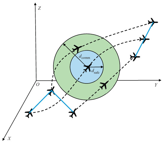
Figure 1.
UAV formation reconfiguration under the constraints of the distance of collision avoidance and communication connection.
- In this paper, we consider a multi-UAV formation reconfiguration problem in a 3-D space. To solve this continuous-variable, non-linear and high-dimensional problem, an optimization problem is first formulated, considering the constraints of the control inputs, the collision avoidance, the communication connection and the terminal state.
- We employ the CPTD method to discretize the continuous variables and transform the formation reconfiguration optimization problem into a discrete-variable optimization problem.
- Then, we propose a modified ABC algorithm to solve the discrete-variable optimization problem. Specifically, a self-adaptive variable is introduced in basic ABC to control the perturbation frequency of each solution according to their objective functions to accelerate the convergence speed.
- Finally, extensive performance evaluations are conducted to verify the superiority of the proposed method. Simulation results show that the modified ABC algorithm achieves a better search performance than the other benchmark algorithms and has a faster convergence speed than the ABC algorithm.
The rest of this paper is organized as follows. Section 2 builds a system model of formation reconfiguration for UAV and formulates its optimization problem. Then, the UAV formation reconfiguration optimization problem is discretized by CPTD in Section 3, transforming it into an optimal control problem, and a modified ABC algorithm is also presented in this section. Section 4 conducts an experiment to prove the effectiveness and superiority of the proposed method compared with other candidate algorithms. Finally, the paper is concluded in Section 5.
2. System Model and Problem Formulation
In this section, we first introduce the motion model of the UAV formation. Then, the constraints of the control inputs, the collision avoidance, the communication connection and the terminal state for UAV formation reconfiguration are discussed. Finally, we formulate an optimization problem based on the motion model to minimize the reconfiguration time of multi-UAV, taking the aforementioned constraints into consideration.
2.1. Motion Model of UAV Formation
In order to build the motion model of the formation under dynamic environment, the following assumptions are essential for UAVs and environment [26]:
- Each UAV can be modelled as a rigid body in a symmetrical shape.
- The weight of the UAV does not change during the flight.
- Gravitational acceleration does not change with altitude during flight.
- The influence of Earth factors, such as the rotation of the Earth and the curvature of the Earth, can be ignored.
Besides, we also assume that there are N UAVs in the formation and the reconfiguration process begins at time and ends at . Then, the state vector of the i-th UAV at time t can be expressed as , where and . is the position of the i-th UAV in the ground coordinate system as shown in Figure 2a, is the barycenter. is the motion state of the i-th UAV, where is the module value of the speed, is the flight-path angle and is the heading angle as shown in Figure 2b. The three axes in are parallel to the axes in the ground coordinate system , respectively. Then, the motion equations of the i-th UAV can be written as [7,27]
where denotes the derivative with respect to time t. The other parameters are listed in Table 1. We define the vector of engine thrust, load factor and roll angle as the control input vector , for and . Then, the overall control input vector of the UAV formation can be represented as . Besides, the state variables of the UAV formation is represented ( and are written as row vectors for the convenience of subsequent descriptions. ) as . Therefore, the motion equation of the formation system can be expressed as:
where function means the set of the motion equations in (1)–(7).

Figure 2.
State variables and control inputs of UAV. (a) the location of UAV. (b) the motion state of UAV. (c) the control inputs of UAV.

Table 1.
Parameters of The Equations (1)–(7).
Based on the continuous control input vector and the initial state variable , the state of the formation at time is:
which means if an initial state is given, then the state can be uniquely determined by the control input for .
2.2. Constraints of UAV Formation Reconfiguration
In this subsection, we discuss the constraints of the control input, the collision avoidance, the communication connection and the terminal state for the UAV formation reconfiguration problem.
- Control input constraint: To be consistent with the actual UAV flying abilities, is constrained by the following inequalities:where , . Constants , , , , and represent the maximum values and the minimum values of the engine thrust, load factor and the roll angle of UAV, respectively.
- Collision avoidance constraint: For the safety of the reconfiguration process, the distance between any two UAVs should be no less than the safety distance to avoid the potential collision between the UAVs, which can be expressed as:where denotes the Euclidean distance between the i-th and the j-th UAVs at time t.
- Communication connection constraint: To guarantee the data transfer between the UAVs, the distance between any two UAVs should be no more than the communication distance , which can be written as:
- Terminal state constraint: To ensure the UAVs of the formation have all reached their desired positions and have achieved the reconfiguration precisely, the difference between the target formation and the UAV formation state at terminal time should be close to zero, i.e.,where the m-th UAV is the center of the formation. In this paper, m is arbitrarily chosen from and does not change during the reconfiguration process. is the desired relative coordinate of the i-th UAV with respect to the center UAV at terminal time T. for and represent the positions of the UAVs at the terminal time T.
2.3. Problem Formulation
In this paper, we consider a time-optimal formation reconfiguration problem. It can be stated as finding a control input , which is a continuous and high-dimensional vector of variables, to minimize the reconfiguration time T and satisfy the constraints simultaneously:
We next integrate most of the constraints into the objective function to simplify problem .
First, we formulate an objective function to evaluate the collision risk between the UAVs during the reconfiguration, which is given by:
Similarly, the objective function of the communication connection can be represented as:
Then, to evaluate the difference between the terminal formation and the target formation, we formulate an objective function as:
Since m is a fixed constant and does not change during the reconfiguration process, it is not written as a variable of to simplify the expression. It is worth emphasizing that represents the relative positions between the UAVs, thus the value of m has a negligible influence on the optimization result. Therefore, the final objective function can be given as:
where , and are the penalty constants for the aforementioned objective functions, respectively.
To this end, constraints (11)–(13) are formulated in (17), and then the new problem can be given as:
Compared with , problem has a more concise expression and can still satisfy the constraints in . However, is still a continuous-variable, non-linear and high-dimensional problem, which means it is still difficult to obtain the optimal solution of . In the next section, a modified ABC based method is introduced to solve .
3. Solution of the 3-D Formation Reconfiguration
In this section, a modified ABC based method is proposed to solve problem . Specifically, we first use the CPTD method to discretize the continuous-variable problem and transform it into a discrete-variable optimization problem . Then, a modified ABC algorithm is designed to solve . By introducing an adaptive variable , the modified ABC algorithm can control the perturbation frequency of each solution thus speeding up the convergence process.
3.1. UAV Discrete Formation Model Based on CPTD
In order to obtain a discrete formation model, we first divide the terminal time interval into segments, where is a fixed constant and each segment has the same length , i.e., . For each time segment interval, we assume the control input of UAV remains unchanged. Thus, the control input vector of the i-th UAV at the j-th time interval can be given by . And the constraint in (10) can be approximated as:
Then, the control input of the i-th UAV for the whole reconfiguration process on the discrete time domain can be given by . Further, to obtain the motion state of the UAV at any time, we define the mapping from the discrete control inputs to the continuous control inputs as:
where is given by:
Therefore, the motion equation in (8) of the formation system can be approximated as:
where and . Time t is still a variable of the Equation (21) since the CPTD method is used only to discretize the value of the control input as Figure 3. Therefore, the motion equations of (21) are still continuous in the time domain during each time segment.
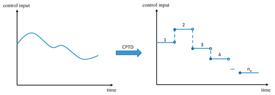
Figure 3.
Control parameterization and time discretization method.
In this way, the variables of are transformed from and T into discrete optimization parameters and , respectively. Further, the objective function can be approximated as:
where is defined as the set of optimization variables. To this end, the formation reconfiguration problem has been transformed into a discrete optimization problem, which can be written as:
3.2. Solution of the 3-D Formation Reconfiguration Problem Based on the Modified ABC Algorithm
Based on the above description, the ABC algorithm can be adopted and modified to solve the 3-D formation reconfiguration problem of the UAVs. ABC algorithm was proposed by Karaboga [28], which imitates the food collecting behavior of bee colony to obtain the optimal solution [29]. Specifically, the ABC algorithm has a unique mechanism of role conversion, as shown in Figure 4, which balances the global search and the local search [30]. The employed bee is responsible for randomly searching for honey sources (solutions) in the domain, and transmits the information about the honey source to the onlooker. Then, the onlooker bee selects the employed bee with roulette method and searches around the food source where the employed bee is located. When the number of onlookers searching near the food source exceeds a certain number which means no better food source is found, onlookers will transform into a scouter bee and randomly search for the food source. In this way, diversity can be guaranteed and local optimum can be avoided. However, only one parameter of the parent solution is updated while producing a new solution which may result in a slow convergence speed [31]. In this paper, the original ABC algorithm is enhanced by introducing a self-adaptive variable to control the perturbation frequency of each solution according to their objective functions. Specifically, more parameters will be changed for the parent solutions with worse objective functions to improve the convergence speed. The steps to solve with the proposed modified ABC algorithm are as follows.
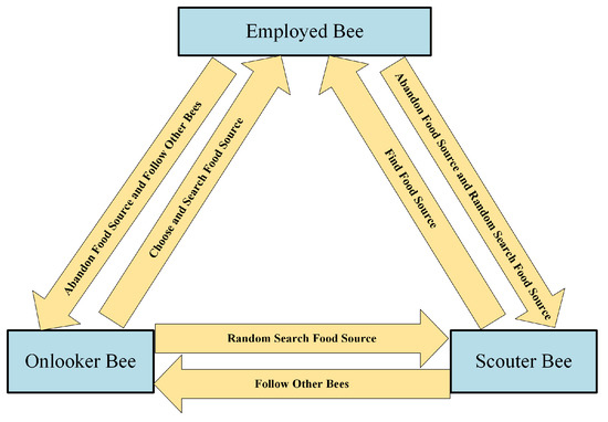
Figure 4.
ABC algorithm role conversion mechanism.
Step 1. Initialization: We randomly initialize the solution set as , where represents the number of food sources (solutions). is the component in the j-th dimension of the i-th initial solution , which is defined as follows:
where is a random number in the range , and represent the maximum value and the minimum value of the j-th dimension of solutions, respectively.
Step 2. Employed bee section: For the iteration index , calculate the objective function for every solution in the solution set . Then, different from basic ABC which only updates one parameter of the solution, we calculate the modification rate for each solution according to their objective function to decide the number of the parameters that will be updated:
where is the dimension of the solutions, and are the minimum value and maximum value of the objective functions among all the solutions in solution set .
Then, the employed bee searches neighborhoods based on the location of the food source in memory, looking for a better source of honey. The formula for every parameter of the new solution is as follows:
where and represent the j-th parameters of the solutions and , respectively. is a random number in the range , R is a random number in the range and k is a random integer in the range . By introducing the self-adaptive modification rate , more parameters can be updated for the solutions with worse objective functions thus improving the perturbation frequency while less parameters are updated for the better solutions to prevent from too much diversity [31].
Then, we calculate the objective function and compare it with the objective function . The one with smaller objective function value is selected as the new honey source.
Step 3. Onlooker bee section: Onlooker bees are hired to collect honey according to the honey source information shared by the employed bees and the formula is as follows:
where is the fitness value of the solution . Every onlooker bee randomly generates a real number p, which is uniformly distributed in the range . If , then the onlooker bee searches for a new solution in the neighborhood. The new solution changes only one parameter of in the j-th component as follows:
where represents the j-th parameter of the new solution , j is a random integer in the range and all the other components are not changed, i.e., for other k. Then calculate the objective function and replace with if is smaller than .
Step 4. Scout bee section: In order to prevent the algorithm from falling into local optimum, if the employed bee does not improve the quality of the solution when the number of searching the honey source neighborhood is greater than a given threshold , the employed bee is converted into a scout bee to randomly searching for a new honey source.
Step 5. Steps (2)–(4) are repeated until the stop condition is met. Details of the proposed algorithm are provided in Algorithm 1.
| Algorithm 1 Modified Artificial Bee Colony |
|
3.3. Computational Complexity and Performance Analysis
Assume that is the dimension of the solution. Then, the initialization complexity of the basic ABC algorithm is as , while the complexity of employed bee to conduct one-dimensional search, the complexity of calculating the probability of solutions being selected and the complexity of onlooker bee to conduct one-dimensional search can all be approximated as . What’s more, the complexity of scout bee to conduct D-dimensional search can be approximated as . Thus, the complexity of the basic ABC algorithm in the whole iteration process can be calculated as:
Compared with the basic ABC algorithm, the modified ABC algorithm introduces a self-adaptive variable during the employed bee section. Therefore, the complexity of employed bee section is transformed from into , and the complexity of the modified ABC algorithm in the whole iteration process can be calculated as:
It can be seen that the complexity of the modified ABC algorithm is higher than the basic ABC. However, considering the fact that the objective function evaluation of the formation reconfiguration problem is quite costly, the computational burden is mostly determined by the number of objective function evaluations [32]. Therefore, the additional complexity caused by introducing the is negligible, and the computational complexities of both basic ABC algorithm and modified ABC algorithm can be approximated as . Besides, it can be concluded from (29) that the computational complexity of the proposed modified ABC algorithm is a polynomial level which is relatively low. Thus, it is promising that a feasible solution can be obtained in an acceptable time duration.
To evaluate the performance of the modified ABC, a comparison between ABC and modified ABC has been conducted using two classical multimodal benchmark functions, i.e., the Ackley function and the Generalized Schwefeląŕs Problem [31]. We execute both algorithms for 100 times and calculate the average value and the standard deviation (std) of the best results in 100 cycles, 300 cycles and 500 cycles as in Table 2. For the Ackley function, the average values of our proposed modified ABC are all less than ABC and the standard deviation is higher than ABC only in the case of 100 cycles. For the Generalized Schwefeląŕs Problem, solutions obtained by our proposed algorithm have lower means but higher stds in all three cases. This can be explained as follows, the introduction of means more parameters will be updated when producing a new solution, thus improving the convergence speed. In the meantime, more updates also introduce higher diversity to the solutions which result in higher stds if the objective function is relatively complex like the Generalized Schwefel’s Problem.

Table 2.
Comparison between ABC and Modified ABC on Classical Benchmark Functions.
4. Simulation Results
In this section, we evaluate the performance of the proposed method compared with other candidate methods. For fairness, we take the same scenario as [25]. In our experiment, the number of UAVs in the formation is set to 5, and the third UAV is set as the center of the formation. The relative position of each UAV with respect to the UAV3 at the initial time and the terminal time are shown in Table 3. The UAVs are expected to move from their former positions to their new positions to form a V-shape formation at the same altitude. To avoid collision during the reconfiguration, the minimum safety distance between UAVs is set as 5 . To guarantee real-time communication between any two UAVs, the maximum communication distance is set as 45 . Besides, the air density /, the wings surface area , the drag coefficient 0.08 and the weight 5000 . Set the number of bee colony , the number of food sources , the number of iterations , and the threshold of the artificial bee colony algorithm .

Table 3.
States of the UAVs at Initial and Terminal Time with respect to the center UAV.
Figure 5 shows the convergence performance on objective functions of PSO, GA, HPSOGA, ABC and Modified ABC, which are averaged through 50 times of simulation of the formation reconfiguration for 5 UAVs. And the parameter values of the benchmark algorithms are shown in Table 4. The objective function is designed as (22), where the collision avoidance penalty coefficient , communication connection penalty coefficient , and terminal state penalty coefficient are set to be large enough to ensure that the whole procedure of the reconfiguration satisfies all the constraints. Specifically, the penalty constants are set as in this paper. Therefore, the objective function of a solution will become very large if the constraints are not satisfied. From Figure 5, it can be seen that our proposed method is better than the benchmarks in the aspect of the search accuracy and convergence speed. The solution obtained with our method improves the final objective function nearly 10 times than the ABC and nearly 100 times than the HPSOGA [25]. In the mean time, the number of iteration cycles is much less than the benchmarks.
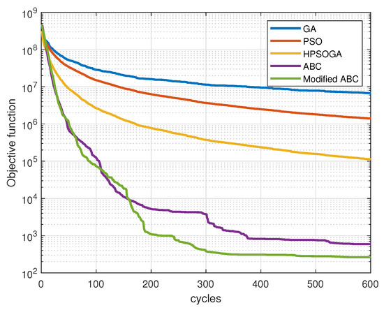
Figure 5.
The average objective function versus iteration cycles with different algorithms.

Table 4.
Parameter Values of The Benchmark Algorithms.
Figure 6 shows the procedure of the UAV formation transforming from the initial state into the desired V-shape formation. Figure 6a displays the trajectories in 3-D space obtained by the proposed approach. Different colors are used to distinguish the trajectories of different UAVs. “∘” represents the initial positions of UAVs, while “×” represents the positions of UAVs at the terminal time. The two dashed lines are the specified reconfiguration formation that the UAVs are expected to reach. It can be seen that the initial orientation of some UAVs are not directly heading to their desired positions. It is because the initial velocity direction of each UAV is arbitrary and our method successfully correct their paths and realize the formation reconfiguration in a short time. Furthermore, to illustrate the effectiveness of our proposed method more clearly. We demonstrate the trajectories in horizontal plane and vertical direction as Figure 6b,c. From the 2-D space, it shows that the final formation can satisfy the specified configuration formation “V”. In the meantime, we can conclude from Figure 6c that all the UAVs have successfully reached the same altitude at the terminal time. In summary, the proposed method can achieve the precise formation reconfiguration for the Multi-UAV system.
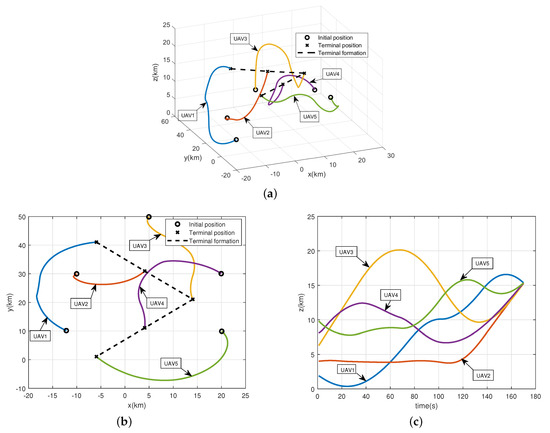
Figure 6.
The reconfiguration trajectories of the UAV formation obtained by modified ABC algorithm. (a) The reconfiguration trajectories of the UAV formation in 3-D space. (b) The reconfiguration trajectories of the UAV formation in horizontal plane. (c) The reconfiguration trajectories of the UAV formation in vertical height.
Figure 7a shows the distance between the UAVs during the reconfiguration process. The upper green line represents the communication connection distance and the lower red line represents the collision avoidance distance. It can be seen that the distance between any two UAVs meets the need of communication among UAVs while keeping the UAVs away from collision at the same time, which proves the feasibility of the trajectory computed by the modified ABC algorithm. Figure 7b–d show the thrust force, lift force and roll angle of each UAV obtained by the proposed method, respectively. It can be seen that all the control inputs satisfy the constraints in Table 5, which means the control inputs obtained by the modified ABC algorithm are feasible.
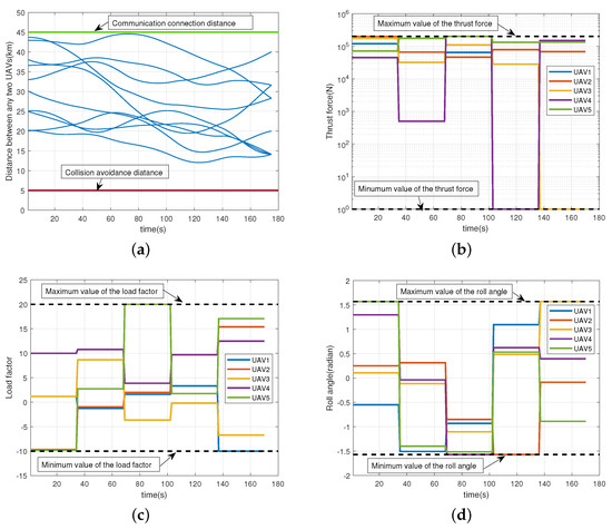
Figure 7.
The constraints of the distance and the control inputs for the UAV formation. (a) The distance between any two UAVs. (b) The thrust force of the UAV formation obtained by modified ABC algorithm. (c) The load factor of the UAV formation obtained by modified ABC algorithm. (d) The roll angle of the UAV formation obtained by modified ABC algorithm.

Table 5.
Maximum and Minimum Values of the control inputs.
To verify the availability of the proposed algorithm, we set up different simulation scenarios with different safety distances, target formations and different numbers of UAVs to test our method. Firstly, we adjust from 5 to 5 , the results in Figure 8 show that the reconfiguration trajectories without collision can still be obtained with our method. Then, we change the target formation to a straight-line shape. It can be seen from Figure 9a,b that the proposed algorithm can still obtain a better solution with a faster convergence speed than the benchmarks. We also increase the number of UAVs to 7 and change the target formation to a triangle-shape formation. Figure 10a displays the trajectories obtained by the proposed approach. It can be seen that we can still achieve the target formation despite the increase of UAV. Figure 10b shows the objective functions of the benchmarks. It can be seen that our proposed method has achieved a better solution with less cycles. Besides, compared with Figure 5, it takes more cycles to find the optimal solution as expected since the increase of UAVs makes it more difficult to find the trajectories of reconfiguration under the constraints.
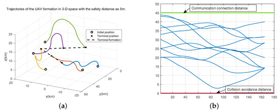
Figure 8.
The simulation results for the formation reconfiguration with the safety distance of 5 m. (a) The reconfiguration trajectories of the UAVs. (b) The distance between any two UAVs.
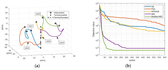
Figure 9.
The simulation results for the formation reconfiguration of forming a straight-line shape with 5 UAVs. (a) The reconfiguration trajectories of the UAVs. (b) Objective function of the benchmarks.
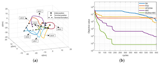
Figure 10.
The simulation results for the formation reconfiguration of forming a triangle-shape with 7 UAVs. (a) The reconfiguration trajectories of the UAVs. (b) Objective function of the benchmarks.
From the simulation results above, we can conclude that the UAVs have perfectly reconfigured the target formation shape based on the CPTD-ABC approach under the constraints of collision avoidance and communication connection. The evaluation of objective values for different algorithms shows that, compared with other benchmarks, the proposed modified ABC algorithm has faster convergence speed and achieves a better solution with lower objective function value in solving the problem of formation reconfiguration. More experiments have been conducted with different numbers of UAVs and different target formations to verify the availability of our proposed method. The results show that our method can find the optimal control inputs under the constraints of collision avoidance and communication connection, and can achieve a better solution than the other algorithms.
5. Conclusions
The continuity, nonlinearity and high dimensionality of the control parameters bring many difficulties in solving the formation reconfiguration problem. Besides, the constraints of the control input, the collision avoidance, the communication connection and the terminal state have to be taken into consideration. In this paper, we have proposed a framework to realize UAV formation reconfiguration by combining a newly proposed modified ABC algorithm with the CPTD method. Specifically, we first formulate the reconfiguration problem into an optimization problem. Then, the method of CPTD is used to discretize the control parameters and transform the optimization problem into a discrete-variable one. Finally, a modified ABC search algorithm is utilized to obtain the optimal control inputs of formation reconfiguration. By introducing a self-adaptive variable, the proposed modified ABC can adjust the number of parameters that are updated while producing a new solution, thus improving the convergence speed. Extensive performance evaluations are conducted to verify the superiority of the proposed method. Simulation results show that the modified ABC algorithm can realize the formation reconfiguration precisely in 3-D space under various constraints. It can also be concluded that the proposed method can achieve a better solution with lower objective function than the other benchmark algorithms with a faster convergence speed in solving the UAV formation reconfiguration problem. However, the communication delay and the location error have not been considered in the motion model of the UAV. These interference factors will affect the trajectories and the terminal positions of the UAV formation and may have influences on the convergence of the proposed method. Therefore, the stability conditions should be considered in the future work.
Author Contributions
Resources, Z.X.; conceptualization, Z.X. and Z.Y.; methodology, Z.X., Z.Y. and F.Y.; writing—original draft preparation, Z.Y. and F.Y.; writing—review and editing, T.M., Z.H. and X.X.; funding aqusition, Z.X. All authors have read and agreed to the published version of the manuscript.
Funding
This research was supported by the National Natural Science Foundation of China (NSFC) under grant numbers 62171010, U22A2007 and 61827901, and the Beijing Natural Science Foundation under grant number L212003.
Institutional Review Board Statement
Not applicable for studies not involving humans or animals.
Informed Consent Statement
The study did not involve humans.
Data Availability Statement
Data sharing not applicable.
Conflicts of Interest
The authors declare no conflict of interest.
References
- Nguyen, M.T.; Le, L.B. Multi-UAV trajectory control, resource allocation, and NOMA user pairing for uplink energy minimization. IEEE Internet Things J. 2022, 9, 23728–23740. [Google Scholar] [CrossRef]
- Wu, Q.; Zeng, Y.; Zhang, R. Joint Trajectory and Communication Design for Multi-UAV Enabled Wireless Networks. IEEE Trans. Wirel. Commun. 2018, 17, 2109–2121. [Google Scholar] [CrossRef]
- Abbas, N.; Mrad, A.; Ghazleh, A.; Sharafeddine, S. UAV-Based Relay System for IoT Networks With Strict Reliability and Latency Requirements. IEEE Netw. Lett. 2021, 3, 110–113. [Google Scholar] [CrossRef]
- Liu, Y.; Liu, K.; Han, J.; Zhu, L.; Xiao, Z.; Xia, X.-G. Resource allocation and 3-D placement for UAV-enabled energy-efficient IoT communications. IEEE Internet Things J. 2021, 8, 1322–1333. [Google Scholar] [CrossRef]
- Xia, Z.; Du, J.; Wang, J.; Jiang, C.; Ren, Y.; Li, G.; Han, Z. Multi-agent reinforcement learning aided intelligent UAV swarm for target tracking. IEEE Trans. Veh. Technol. 2022, 71, 931–945. [Google Scholar] [CrossRef]
- Gupta, L.; Jain, R.; Vaszkun, G. Survey of Important Issues in UAV Communication Networks. IEEE Commun. Surv. Tutor. 2016, 18, 1123–1152. [Google Scholar] [CrossRef]
- Li, B.; Zhang, J.; Dai, L.; Teo, K.L.; Wang, S. A hybrid offline optimization method for reconfiguration of multi-UAV formations. IEEE Trans. Aerosp. Electron. Syst. 2021, 57, 506–520. [Google Scholar] [CrossRef]
- Wubben, J.; Aznar, P.; Fabra, F.; Calafate, C.T.; Cano, J.-C.; Manzoni, P. Toward secure, efficient, and seamless reconfiguration of UAV swarm formations. In Proceedings of the IEEE/ACM 24th International Symposium on Distributed Simulation and Real Time Applications, Prague, Czech Republic, 14–16 September 2020. [Google Scholar]
- Wang, K. Minimum-fuel formation reconfiguration of multiple free-flying spacecraft. J. Astronaut. Sci. 1999, 47, 77–102. [Google Scholar] [CrossRef]
- Woods, A.C.; La, H.M. A novel potential field controller for use on aerial robots. IEEE Trans. Syst. Man Cybern. Syst. 2019, 49, 665–676. [Google Scholar] [CrossRef]
- Trejo, J.A.V.; Ponsart, J.-C.; Adam-Medina, M.; Valencia-Palomo, G.; Theilliol, D. Distributed Observer-based Leader-following Consensus Control for LPV Multi-agent Systems: Application to multiple VTOL-UAVs Formation Control. In Proceedings of the 2023 International Conference on Unmanned Aircraft Systems (ICUAS), Warsaw, Poland, 6–9 June 2023. [Google Scholar]
- Saif, A.W.; Alabsari, N.; Ferik, S.E.; Elshafei, M. Formation control of quadrotors via potential field and geometric techniques. Int. J. Adv. Appl. Sci. 2020, 7, 82–96. [Google Scholar]
- El-Ferik, S.; Maaruf, M.; Al-Sunni, F.M.; Saif, A.A.; Al Dhaifallah, M.M. Reinforcement Learning-Based Control Strategy for Multi-Agent Systems Subjected to Actuator Cyberattacks During Affine Formation Maneuvers. IEEE Access 2023, 11, 77656–77668. [Google Scholar] [CrossRef]
- Peng, Z.; Jikai, L. On new UAV flight control system based on Kalman & PID. In Proceedings of the 2011 2nd International Conference on Intelligent Control and Information Processing, Harbin, China, 25–28 July 2011. [Google Scholar]
- Bai, X.; He, Y.; Xu, M. Low-thrust reconfiguration strategy and optimization for formation flying using jordan normal form. IEEE Trans. Aerosp. Electron. Syst. 2021, 57, 3279–3295. [Google Scholar] [CrossRef]
- Kan, Z.; Navaravong, L.; Shea, J.M.; Pasiliao, E.L.; Dixon, W.E. Graph matching-based formation reconfiguration of networked agents with connectivity maintenance. IEEE Trans. Control Netw. Syst. 2015, 2, 24–35. [Google Scholar] [CrossRef]
- Zhang, H.; Zhang, G.; Yang, R.; Feng, Z.; He, W. Resilient Formation Reconfiguration for Leader-Follower Multi-UAVs. Appl. Sci. 2023, 13, 7385. [Google Scholar] [CrossRef]
- Shen, K.; Shivgan, R.; Medina, J.; Dong, Z.; Rojas-Cessa, R. Multidepot drone path planning with collision avoidance. IEEE Internet Things J. 2022, 9, 16297–16307. [Google Scholar] [CrossRef]
- Wu, E.; Sun, Y.; Huang, J.; Zhang, C.; Li, Z. Multi UAV cluster control method based on virtual core in improved artificial potential field. IEEE Access 2020, 8, 131647–131661. [Google Scholar] [CrossRef]
- Lee, K.; Dissanayake, M. Numerical solution for a near-minimum-time trajectory for two coordinated manipulators. Eng. Optim. 1998, 30, 227–247. [Google Scholar] [CrossRef]
- Furukawa, T. Time-subminimal trajectory planning for discrete non-linear systems. Eng. Optim. 2002, 34, 219–243. [Google Scholar] [CrossRef]
- Furukawa, T.; Durrant-Whyte, H.F.; Bourgault, F.; Dissanayake, G. Time-optimal coordinated control of the relative formation of multiple vehicles. In Proceedings of the IEEE International Symposium on Computational Intelligence in Robotics and Automation, Kobe, Japan, 16–20 July 2003. [Google Scholar]
- Gao, C.Y.; Ma, J.F.; Li, T.; Shen, Y.L. Hybrid swarm intelligent algorithm for multi-UAV formation reconfiguration. Complex Intell. Syst. 2023, 9, 1929–1962. [Google Scholar] [CrossRef]
- Xiong, W.; Chen, Z.; Zhou, R. Optimization of multiple flight vehicle formation reconfiguration using hybrid genetic algorithm. In Proceedings of the 1st Chinese Guidance, Navigation Control Conference, Beijing, China, 3–5 November 2007. [Google Scholar]
- Duan, H.; Luo, Q.; Shi, Y.; Ma, G. Hybrid particle swarm optimization and genetic algorithm for multi-UAV formation reconfiguration. IEEE Comput. Intell. Mag. 2013, 8, 16–27. [Google Scholar] [CrossRef]
- Rashad, R.; Califano, F.; Stramigioli, S. Port-Hamiltonian Passivity-Based Control on SE(3) of a Fully Actuated UAV for Aerial Physical Interaction Near-Hovering. IEEE Rob. Autom. Lett. 2019, 4, 4378–4385. [Google Scholar] [CrossRef]
- Li, B.; Sun, J.; Zhou, W.; Wen, C.-Y.; Low, K.H.; Chen, C.-K. Transition optimization for a VTOL tail-sitter UAV. IEEE/ASME Trans. Mechatron. 2020, 25, 2534–2545. [Google Scholar] [CrossRef]
- Karaboga, D. An Idea Based on Honey Bee Swarm for Numerical Optimization; Technical Report-TR06; Erciyes University, Engineering Faculty, Computer Engineering Department: Kayseri, Turkey, 2005. [Google Scholar]
- Karaboga, D.; Basturk, B. A powerful and efficient algorithm for numerical function optimization: Artificial bee colony (ABC) algorithm. J. Glob. Optim. 2007, 39, 459–471. [Google Scholar] [CrossRef]
- Pang, B.; Teng, Z.; Sun, H.; Du, C.; Li, M.; Zhu, W. A Malicious Node Detection Strategy Based on Fuzzy Trust Model and the ABC Algorithm in Wireless Sensor Network. IEEE Wirel. Commun. Lett. 2021, 10, 1613–1617. [Google Scholar] [CrossRef]
- Akay, B.; Karaboga, D. A modified artificial bee colony algorithm for real-parameter optimization. Inf. Sci. 2012, 192, 120–142. [Google Scholar] [CrossRef]
- Cai, Y.; Wang, J. Differential evolution with neighborhood and direction information for numerical optimization. IEEE Trans. Cybern. 2013, 43, 2202–2215. [Google Scholar] [CrossRef] [PubMed]
Disclaimer/Publisher’s Note: The statements, opinions and data contained in all publications are solely those of the individual author(s) and contributor(s) and not of MDPI and/or the editor(s). MDPI and/or the editor(s) disclaim responsibility for any injury to people or property resulting from any ideas, methods, instructions or products referred to in the content. |
© 2023 by the authors. Licensee MDPI, Basel, Switzerland. This article is an open access article distributed under the terms and conditions of the Creative Commons Attribution (CC BY) license (https://creativecommons.org/licenses/by/4.0/).