Abstract
Unmanned aerial vehicles (UAVs) and reconfigurable intelligent surfaces (RIS) are the promising emerging technologies proposed for the 6th-Generation (6G) network to improve the capacity, reliability, and coverage of wireless communications. By integrating the UAV with RIS (RIS-UAV), the three-dimensional (3D) mobility of the UAV can be leveraged to establish strong line-of-sight links with the ground nodes, while the RIS intelligently reflect the signals toward the desired directions. However, the existing literature on RIS-UAV systems mainly assumes the use of passive elements, which suffers from the double path-loss problem. The use of active elements in RIS, which could improve the reflected link performance at the cost of increased energy consumption, has not been considered for the RIS-UAV system. Further, the energy efficiency of a RIS-UAV with active elements remains as an open direction because there is a need to investigate the feasibility of either an active or hybrid RIS-UAV implementation. This paper proposes active and hybrid RIS-UAVs and investigates the energy efficiencies of active and hybrid RIS-UAVs in comparison with existing passive RIS-UAVs and conventional UAV relays. The numerical results reveal that the proposed hybrid and active RIS-UAV relaying schemes can provide up to 14 times and 26 times improvement as compared to the passive RIS-UAV, respectively. As opposed to the active RIS-UAV that requires a larger power budget, half-duplex UAV relays that have a lower spectral efficiency, and full-duplex UAV relays that suffer from self-interference, the hybrid RIS-UAV emerges as a promising option to assist the ground communication system.
1. Introduction
Unmanned aerial vehicles (UAVs), usually known as drones, are aircraft controlled autonomously by a program or manually by a ground controller without a human pilot onboard. The easy deployability, mobility, and flexibility of UAVs have enabled them to provide services across a wide range of applications, including surveillance, remote sensing, military, photography, logistics, telecommunications, etc. [1].
In recent years, UAV communications were considered in Fifth-Generation (5G)-and-beyond networks. On one hand, UAVs can be connected as user equipment (UE) to provide real-time services, such as video streaming, precision agriculture, etc. [2]. On the other hand, UAVs can serve as aerial base stations (BSs) to provide a seamless and ubiquitous connectivity in the future wireless network when the terrestrial BSs are overloaded or out of service due to natural disasters [3]. In addition, UAVs can also act as mobile relay nodes to improve the coverage and reliability of ground communication systems. Compared to the conventional ground relays that are fixed at ground locations, the combination of UAVs and relays takes advantage of the maneuverability of UAVs to provide additional degrees of freedom to the communication links. This combination ensures a high probability of the line of sight (LoS) with the ground nodes, thus improving the rate and reliability of the communication systems [4,5].
Meanwhile, reconfigurable intelligent surfaces (RIS), also known as intelligent reflecting surfaces (IRS) or large intelligent surfaces (LIS), have been envisaged as a new promising paradigm to assist the beyond-5G wireless communication system. RIS are a reconfigurable metasurface which consists of massive low-cost reflecting elements that can manipulate the propagation environment by adjusting the amplitude, phase shift, frequency, and polarization of the incident signals [6]. As a result, RIS are considered to serve as a relay node in order to reflect the signal toward the users [7]. Generally, there are two types of reflecting elements RIS can be equipped with, either active or passive. Active RIS elements can reflect the signals with amplification, whereas passive RIS elements reflect the signal without any signal modification. The active RIS elements introduce thermal noise, while the passive RIS elements suffer from the double path-loss problem, which degrades the signal strength significantly. To overcome these issues, hybrid RIS were introduced [8], in which one or a few elements are integrated with the power amplifier to act as active elements, while the remaining elements are passive.
There are a number of published contributions that compare the system performance between the RIS and the active relays. For instance, the comparisons between passive RIS and an amplify-and-forward (AF) relay are investigated in [6] in terms of the achievable rate, [9] in terms of the energy efficiency, and [10] in terms of the signal-to-noise ratio (SNR), outage probability, ergodic capacity, and symbol error rate. Apart from that, the rate of a decode-and-forward (DF) UAV relay-aided system is compared to that of a passive RIS in [11], while the number of passive RIS elements that are required to outperform the DF relay is investigated in [12]. From the findings of [12], a large number of RIS elements are required to outperform the DF relay due to the double path-loss effect.
Rather than being limited to ground deployment, RIS can potentially be mounted on a UAV (RIS-UAV) to achieve ubiquitous and reliable wireless connectivity. Owing to the mobility and flexibility of UAVs in a three-dimensional (3D) space, a RIS-UAV can provide a panoramic full-angle reflection as opposed to the half-space reflection and multiple reflections by the terrestrial RIS [13,14]. Furthermore, the RIS-UAV can be dynamically deployed to maintain a favorable communication environment where the terrestrial RIS are usually fixed on the facades of a building or at a dedicated location. As such, the RIS-UAV has been a popular research topic in recent years [15,16,17] to serve as a mobile relay node to forward the incident signal toward the destinations, especially when the direct links between the source and destination are weak or blocked by obstacles. However, the existing RIS-UAVs mostly comprise passive elements only, in which the RIS-UAV reflects the signals without signal regeneration or amplification. Hence, the passive RIS-UAV suffers from the double path-loss problem, especially when the passive RIS-UAV is placed distant from the BS and UE [6,17]. Even though active and hybrid terrestrial RIS are demonstrated to obtain a better performance than the passive terrestrial RIS in [18] and [8], respectively, the application of active and hybrid RIS-UAVs in assisting ground communication is still an open issue.
To date, there have been several comparative studies between terrestrial RIS and active relays, but their comparison in UAV-assisted communication is still limited. The comparison of the energy efficiency between a passive RIS-UAV and the full–duplex DF UAV relay is examined in [17]; however, the half-duplex UAV relaying mode is not taken into consideration. Despite the fact that the full-duplex relaying scheme has twice the spectral efficiency of the half-duplex relaying scheme, the half-duplex relaying scheme is free of interference, while the full-duplex relaying scheme experiences self-interference. Furthermore, Refs. [19,20] investigate the performance between a passive RIS-UAV and the conventional AF UAV relay. The simulated results reveal that the passive RIS-UAV yields a higher energy efficiency than the AF UAV relay.
This paper proposes the use of active and hybrid RIS-UAVs in assisting ground communications and investigates the energy efficiencies of the active, hybrid, and passive RIS-UAVs, as well as the conventional UAV relays. The main contributions of this paper are summarized as follows:
- We propose the use of active and hybrid RIS-UAVs to assist ground communication with ground-to-air (G-A) and air-to-ground (A-G) channel modeling.
- The energy efficiencies of active and hybrid RIS-UAVs are analyzed and compared to that of existing passive RIS-UAVs and the conventional DF and AF UAV relays, considering the total power budget. A practical power consumption model is applied, which captures not only the transmit power at the BS and RIS or relay but also includes the hardware power consumption, namely the power consumption of the control circuit and phase shift switch of the RIS that scales with the number of total reflecting elements, the power consumption of the direct current (DC) biasing at each active RIS element, as well as the hardware-dissipated power at the BS, UE, and relay.
- The comprehensive comparison of the energy efficiency of all the RIS-UAVs and UAV relaying schemes is presented with varying system parameters, including the placement and altitude of the UAV, the number of total reflecting elements, the number of active elements in the hybrid RIS-UAV, and the total power budget.
- The comprehensive comparison between the RIS-UAVs and UAV relaying schemes reveals that the active and hybrid RIS-UAVs, which exploit the benefit of signal amplification using active elements, outperform the passive RIS-UAV and conventional UAV relays. Even with a single active element, the hybrid RIS-UAV performs better than the passive RIS-UAV, in which the performance gain can be up to 14 times if compared to the passive RIS-UAV.
The rest of this paper is organized as follows. In Section 2, the channel model of the UAV and the SNR of each of the RIS-UAVs and the UAV relaying scheme are discussed. In Section 3, the simulation results are presented to evaluate the performance of each of the RIS-UAVs and the UAV relaying scheme. Finally, discussions are made and concluded in Section 4.
2. System Model
In this paper, we consider a downlink UAV-assisted communication system, as illustrated in Figure 1. In practice, RIS-UAV is relevant in various scenarios. A UAV equipped with RIS or relay, for example, could function as a mobile RIS or mobile relay to extend the network coverage in an urban environment where signals suffer from severe shadowing and blocking due to dense high-rise buildings [21]. As another example, the mobile UAV relay and RIS-UAV could fly around to establish favorable condition links for vehicular users [22].
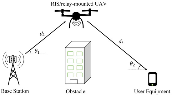
Figure 1.
UAV-assisted communication.
In our considered model, a rotary-wing UAV, equipped with either RIS or active relay, serves as a mobile RIS or relay node to assist the communication between a BS and the UE, where the direct link between BS and UE is blocked. Both the BS and UE are equipped with only a single antenna, and their positions are fixed. In addition, the UAV will hover at a certain altitude. For the RIS elements mounted on the UAV, each of them is half of the size of the wavelength; hence, the elements reflect the signal with constant gain toward the desired direction [12]. The definition of parameters is listed in Table A1 and Table A2 in Appendix A.
The locations of BS, UAV, and UE in 3D Cartesian coordinates are , , and , respectively. Additionally, the locations of BS, UE, and UAV in 2D Cartesian coordinates can be denoted as , and respectively. Therefore, the distance between the BS and the UAV, can be defined as:
while the distance between the UAV and the UE, , can be defined as:
The G-A and A-G channel links between BS and the UAV, and between UAV and the UE, respectively, are computed using Al-Hourani’s channel model with Rician fading as introduced in [23]. Accordingly, the probability of LoS for each channel link is defined as follows:
where a and b are the constant environmental parameters, and is the elevation angle between the UAV and the ground nodes. The elevation angle between the BS and UAV is given as:
whereas the elevation angle between the UAV and the UE is given as:
In addition, the probability of non-LoS (NLoS) for each channel link is defined as:
Meanwhile, the channel gains between the BS and the UAV, and between the UAV and the UE, are defined as [24]:
where A represents the effect of the antenna gain and operating frequency, and are the independent and identically distributed (i.i.d) random variables that follow a Rician distribution, while and are the aerial path-loss exponents for the links between BS and UAV, and between UAV and the UE, respectively. In detail, the constant coefficient, A, is defined as:
where is the operating frequency and c is the speed of light. The Rician fading channel model is adopted in this paper due to the possible existence of LoS and NLoS paths between the BS and UE. In other words, the received signals at the UE comprise both direct wave and multipath scatterers. By referring to [25], the Rician factor that varies with the elevation angle is defined as:
where is the minimum Rician factor and is the maximum Rician factor. In addition, the aerial path-loss exponents are computed as:
where and are the constant values based on the probability of LoS and NLoS.
2.1. Proposed Active RIS-UAV
In the proposed active RIS-UAV relaying scheme, active RIS elements are mounted on the UAV to assist the communication between BS and UE. The active RIS-UAV is responsible for amplifying and reflecting the received signal from the BS toward the UE. In this paper, we assume that the RIS elements reflect the signals independently [8]. In addition, the distance between BS and the -th element of RIS is assumed to be approximately the same as the distance between BS and the UAV because the size of the RIS elements is much smaller than the wavelength. Similarly, assuming that the distance between the -th element of RIS and UE is approximately the same as the distance between UAV and UE. Thus, the received signal at the UE after being amplified and reflected by the proposed active RIS-UAV is given as [26]:
where is the BS transmit power of the active RIS-UAV relaying scheme, s is the information signal transmitted by the BS, and represent the thermal noise at the active elements and UE, respectively. In addition, the parameter is the reflection matrix of the active elements, , in which and represent the amplification factor and the phase shift of the -th RIS element, respectively, where and For simplicity, is assumed to be the same for all active elements, where . In general, the amplification gain is the extent to which the power amplifiers of the active elements of RIS-UAV boost the strength of a signal. Therefore, the amplification gain is applied to offset the path loss between the BS and the RIS-UAV, such that the denominator is the channel coefficient and the effective noise term, while the numerator is the scaling constant. The amplification gain can be formulated as follows [26]:
where is the transmit power at the active RIS-UAV. Therefore, the SNR for the proposed active RIS-UAV relaying scheme is expressed as:
We assume that all the reflected signals arrive in the same phase at the UE; hence, the simplified SNR is:
2.2. Proposed Hybrid RIS-UAV
For the proposed hybrid RIS-UAV relaying scheme, the RIS mounted on the UAV consists of discrete elements, including L active and passive reflecting elements. Therefore, the hybrid RIS-UAV can be modified to become an active RIS-UAV or passive RIS-UAV by changing the number of active elements. For instance, the hybrid RIS-UAV becomes a passive RIS-UAV if , whereas it becomes an active RIS-UAV if . After being reflected by hybrid RIS-UAV, the received signal at the UE is given as [8,26]:
where represents the BS transmit power of the hybrid RIS-UAV relaying scheme. In addition, and are the reflection matrix of the passive and active RIS elements, respectively, where and
The notation is the index set that denotes the positions of L active RIS elements. Similarly, and it can be formulated as:
where is the transmit power of the hybrid RIS-UAV,
Furthermore, the SNR of the proposed hybrid RIS-UAV is expressed as:
and can be simplified as:
2.3. Passive RIS-UAV
In the existing passive RIS-UAV relaying scheme, the RIS mounted on the UAV consists of only passive elements. The passive RIS-UAV only reflects the incident signals without amplifying it, hence , and there is no noise introduced at the passive RIS-UAV, . As a result, the received signal at the UE after being reflected by the passive RIS-UAV is:
where is the transmit power at the BS for the passive RIS-UAV relaying scheme, while is the reflection matrix of the passive RIS elements, . Therefore, the SNR of the passive RIS-UAV is given as:
2.4. Half-Duplex UAV Relay
In this existing scheme, the half-duplex relay is mounted on the UAV to assist the signal transmission from the BS to the UE. In the first phase, the BS transmits the signals to the UAV relay, and then the UAV relay processes and forwards the signals to the UE in the second phase. For the signal processing, the signals are decoded by the DF relaying scheme, whereas the AF relaying scheme amplifies the signal before retransmitting it to the UE. The received signals at the half-duplex UAV relay and the UE are defined as [12]:
where and are the transmit power at the BS and the UAV relay, respectively, while is the thermal noise introduced at the UAV relay. The end-to-end SNR for the half-duplex DF, , and AF UAV relays, , are defined as:
respectively. In addition, represents the amplification factor of the half-duplex AF UAV relay, where
2.5. Full-Duplex UAV Relay
In contrast to the half-duplex relaying scheme, the signals are transmitted and received simultaneously in the existing full-duplex UAV relaying scheme. Therefore, the full-duplex UAV relay suffers from residual self-interference as the signal leakage from the transmitter’s output to its input. The end-to-end SNR for the full-duplex DF, , and AF UAV relays, , are defined as:
where and are the transmit power of the BS and the full-duplex UAV relay, respectively, and is the residual self-interference experienced by the full-duplex UAV relays. The amplification factor of the full-duplex AF UAV relay, is expressed as:
2.6. Energy Efficiency
The performance metric used in this paper is energy efficiency. Energy efficiency is defined as the ratio of the corresponding rate to the total power consumption, as follows:
where B is the system bandwidth, is the corresponding SNR of each relaying scheme, and is the total power consumption. In this paper, we assume the total power budget for all the RIS-UAVs and UAV relaying schemes is the same for fair comparison. Hence, the transmit power available for active RIS-UAV relaying scheme, ; hybrid RIS-UAV relaying scheme, ; passive RIS-UAV relaying scheme, ; half-duplex UAV relaying scheme, ; and full-duplex UAV relaying scheme, , can be computed as [12,26]:
respectively, where is the power consumption of the control circuit and phase shift switch at each RIS element, is the power consumption of DC biasing at each active RIS element, while , , and are the hardware-dissipated power at the BS, UE, and UAV relay, respectively. The BS of the half-duplex relaying scheme is only active half of the time; hence, its hardware-dissipated power at the BS is only half of the other relaying schemes. In addition, fixed power allocation is assumed for each relaying scheme, where equal power is allocated to the BS and RIS-UAV or UAV relays to transmit the signals.
3. Results
In this section, the numerical simulation results are presented to evaluate the energy efficiency performance of different relaying schemes in supporting the communication between the BS and UE. All the results are obtained by averaging over 50,000 independent channel realizations. Unless stated otherwise, the simulation parameters listed in Table 1 are used to simulate the findings, which are based on [9,18,25,26]. Specifically, the environment parameters are according to the dense urban scenarios. In addition, assuming that the UAV relays are equipped with only a single antenna, the number of reflecting elements in the active, hybrid, and passive RIS-UAVs is fixed at 256. The example size of the RIS operating at 2.3 GHz is about 800 mm × 800 mm, as demonstrated by the prototype shown in [27]. This form factor is feasible to be mounted on a hexacopter, such as the Tarot X6. In order to study the fundamental performance of the proposed hybrid RIS-UAV, a hybrid RIS-UAV is equipped with only a single active element, and the remaining 255 elements are passive. Furthermore, all the channels are assumed to be uncorrelated in this paper; hence, there is no signal coupling in the reflection by the neighboring antenna or elements, and all the elements reflect the incident signal independently to the UE. The hardware-dissipated power at the BS, UAV, and UE, as well as the RIS elements are based on [9,18,26].

Table 1.
Simulation Parameters.
First, the energy efficiencies of the relaying schemes are compared in Figure 2 by varying the placement of the UAV such that the UAV moves its horizontal distance from the BS toward the UE, i.e., from coordinate (0, 0, 20) to coordinate (100, 0, 20). From Figure 2, it is revealed that the proposed active RIS-UAV achieves a higher energy efficiency than other relaying schemes, no matter if the UAV is placed close to the ground nodes or far away from them. This observation was validated with [26] that compared the achievable rate between the active and passive terrestrial RIS with the same total power budget. In [26], it is demonstrated that the active terrestrial RIS outperform the passive terrestrial RIS in all the terrestrial RIS deployments. In addition, the active RIS-UAV is more energy efficient when the UAV is placed in the middle point between the BS and UE due to the equal allocation of the transmit power between the BS and RIS. In contrast, the passive RIS-UAV suffers from the double path-loss problem when the UAV is placed near the middle point of the BS and UE, so it can be observed that the energy efficiency of the passive RIS-UAV drops significantly when the UAV is moving away from the BS and increases back again when it is approaching the UE. Meanwhile, the proposed hybrid RIS-UAV, which consists of a single active element and passive elements, performs better than the passive RIS-UAV. It is revealed that the proposed active and hybrid RIS-UAV relaying schemes can provide up to 26 times and 14 times improvement in energy efficiency as compared to the passive RIS-UAV, respectively, when the UAV is placed in the middle between the BS and UE. When the UAV is placed close to the BS or UE, the performance of the proposed active and hybrid RIS-UAVs is about 187% and 18.9% higher than the passive RIS-UAV, respectively. This is because they can amplify the signal with the power amplifiers integrated with the active elements, hence improving the received signal at the UE. The amplification factor of the hybrid RIS-UAV is computed through the simulation in the range of to . The amplification factor increases as the channel link between the BS and UAV becomes weaker.
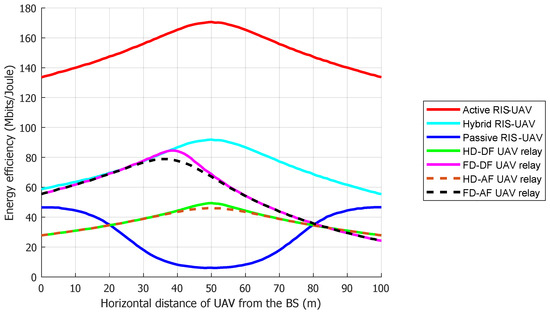
Figure 2.
Energy efficiency versus the horizontal distance of UAV from the BS.
Compared to the conventional half-duplex and full-duplex UAV relays, the proposed hybrid and active RIS-UAVs are superior. This is because the performances of the full-duplex UAV relays are limited by the 10 dB of residual self-interference, and it is well-known that the full-duplex relays cannot fully cancel their self-interference even with the recent technologies. On the other hand, the energy efficiency of the half-duplex UAV relays is lower than other relaying schemes because they transmit the signals using two time slots due to the half-duplex constraints. However, when the UAV is placed near the UE, the half-duplex UAV relays can even outperform the full-duplex UAV relays as the full-duplex UAV relays experience a weak channel gain between the BS and UAV relays and also its residual self-interference. Furthermore, the figure shows that the DF UAV relay achieves a higher energy efficiency than the AF UAV relays because the noise is amplified by the AF UAV together with the attenuated signals.
In addition, Figure 3 studies the performance of the relaying schemes by varying the altitude of the UAV. In order to study the impact of the UAV’s altitude and elevation angle on the energy efficiency performance of different relaying schemes, the UAV is placed in the middle between the BS and UE.
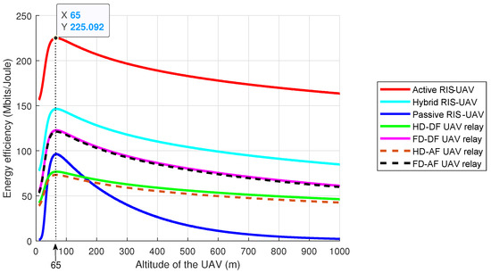
Figure 3.
Energy efficiency versus altitude of the UAV.
As shown in Figure 3, the energy efficiencies of all the schemes increase with the altitude of the UAV. This is due to the increase in the elevation angle between the UAV and the ground nodes, which provides a better clearance from the ground obstructions, such as buildings and other man-made structures. As a result, the probability of the LoS and Rician factor increase, as the Rician factor is defined as the ratio of the power in the LoS component to the power in the NLoS components. The higher the probability of the LoS, the higher the Rician factor. The high Rician factor strengthens the channel gain between the UAV and the ground nodes, thus improving the SNR of the relaying schemes. In short, the energy efficiencies of all the relaying schemes increase as the altitude of the UAV increases, as validated with the Al-Hourani model [23]. However, it can be observed that the energy efficiencies of all the schemes decrease after the UAV’s altitude increases to above 65 m in height. The increase in the distance between the UAV and the ground nodes has caused a higher path loss to be experienced by the A-G channel, thus degrading the system performance.
Furthermore, Figure 3 demonstrates that the proposed active RIS-UAV is superior to other relaying schemes in all the UAV deployments. Similar to Figure 2, when the UAV is placed in the middle between the BS and UE, the energy efficiency of the proposed hybrid RIS-UAV is higher than the passive RIS-UAV, even if the altitude of the UAV increases. This is because the passive RIS-UAV experiences severe double path-loss problems when the UAV is placed in the middle between the BS and UE. Additionally, the proposed hybrid RIS-UAV also outperforms the half-duplex and full-duplex UAV relays. On one hand, the hybrid RIS-UAV performs better than the half-duplex UAV relays because the hybrid RIS-UAV can receive and transmit the signals simultaneously. On the other hand, the hybrid RIS-UAV is more energy efficient than the full-duplex UAV relays because the full-duplex UAV relays suffer from residual self-interference. In addition, as the passive RIS-UAV works in the full-duplex mode, it achieves a higher energy efficiency than the half-duplex UAV relay when the altitude of the UAV increases. Moreover, it can be noticed that the DF UAV relay outperforms the AF UAV relay because the latter forwards amplified noise to the UE during the signal forwarding.
Figure 4 investigates the effect of increasing the antennas or elements on the energy efficiency performance of different relaying schemes. The coordinate of the UAV is fixed at the coordinate (90, 0, 20), i.e., the UAV is placed near to the UE, to enable a comparison between the RIS-UAVs and UAV relays. Specifically, Figure 4 is simulated to investigate the scaling effect of increasing the number of antennas or elements, without considering whether the dimensions of the RIS or relay are feasible to be mounted on the UAV.
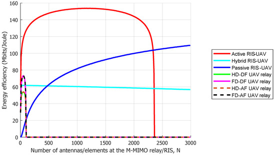
Figure 4.
Energy efficiency versus number of antennas/elements at the M-MIMO UAV relay/ RIS-UAV.
From Figure 4, the proposed active RIS-UAV outperforms the other relaying schemes when the number of elements is small, thanks to its amplification capability to amplify the attenuated signal while reflecting it to the UE. However, the energy efficiency of the active RIS-UAV degrades to zero when the number of elements becomes very large because the power budget is insufficient to supply its hardware components, thus failing to transmit signals. On the other hand, because the hardware power consumption of passive RIS-UAV is much smaller, and its SNR scales with , thus making it more energy efficient when the number of elements is very large. The observation is in line with the result reported in [26] for terrestrial RIS. For the proposed hybrid RIS-UAV, its energy efficiency has steadily declined as the number of elements grows because the SNR of the hybrid RIS-UAV is significantly affected by its amplification factor, and this factor remains nearly constant, even increasing the number of elements. This is because of the weak channel gain between the BS and RIS-UAV; hence, the same amount of the amplification factor is required to amplify and reflect the signals. As a result, the steady decline in the energy efficiency performance of the hybrid RIS-UAV is only due to the decrease in the available transmit power. Moreover, it can be observed that the energy efficiencies of the conventional half-duplex and full-duplex UAV relays drop significantly when the number of antennas increases because the power budget is inadequate to supply the UAV relays’ hardware components and circuits. In other words, the UAV relays can only be equipped with a small number of antennas because the hardware-dissipated power at each antenna is substantially larger than the RIS elements as they are equipped with the radio-frequency chains.
Generally, a higher number of antennas will increase the dimensions of the RIS and relays because an adequate distance is required between the antennas or RIS elements in order to ensure the channels are uncorrelated. In practice, there is a trade-off between the number of antennas or elements and the size of the relay or RIS, such that the higher number of elements can provide a higher energy efficiency to the system, but its dimensions might grow larger until a point where it might not be feasible to be mounted on the UAV. If a smaller size of the RIS or relay is used, the energy efficiency of the relaying schemes will be lower. Hence, the number of antenna elements has to be chosen carefully in order to be mounted on the UAV feasibly while providing a good performance to the system. In short, an active RIS-UAV is preferred because it can achieve a higher energy efficiency, even if the number of elements is small.
By increasing the number of active elements while maintaining the position of the UAV at coordinate (90, 0, 20), Figure 5 shows the performance improvement in the proposed hybrid RIS-UAV in terms of the energy efficiency. The performance curve of the hybrid RIS-UAV is validated with the SNR equation of the hybrid RIS-UAV that shows the scaling factor of . As shown in Figure 5, the energy efficiency of the hybrid RIS-UAV increases in logarithmic growth as the number of active elements grows, and it matches with the performance of a fully active RIS-UAV once the number of active elements in the hybrid RIS-UAV is equal to the total number of elements, N. Specifically, Figure 5 reveals that the proposed hybrid RIS-UAV outperforms the passive RIS-UAV, even with a small number of active elements. The proposed hybrid RIS-UAV is able to double the energy efficiency of the passive RIS-UAV by equipping it with only seven active elements and triple the performance of the passive RIS-UAV with 156 active elements.
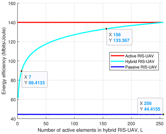
Figure 5.
Energy efficiency versus the number of active elements in the hybrid RIS-UAV.
Finally, the energy efficiencies of different relaying schemes versus the total power budget are demonstrated in Figure 6. The result shows that if the total power budget is sufficient for the proposed active RIS-UAV to supply its hardware components, i.e., greater than 21 dBm, then the active RIS-UAV outperforms the other relaying schemes. This is in line with the observation in [26] for terrestrial RIS. In contrast, the half-duplex DF and AF UAV relays achieve the highest energy efficiency among the other schemes when the total power budget is smaller than 17 dBm. This is because the BS of the half-duplex UAV relaying scheme is only active half of the time; hence, more power is available to transmit the signals. However, as the total power budget increases, the hybrid and passive RIS-UAVs gradually outperform the half-duplex UAV relays because the RIS-UAVs can transmit and receive the signal simultaneously. In addition, the proposed hybrid RIS-UAV is able to achieve a higher energy efficiency than the passive RIS-UAV as it can amplify the attenuated signals and reflect them to the UE. As opposed to the active RIS-UAV that requires a larger power budget, the hybrid RIS-UAV can save up to 5 dBm while achieving an acceptable energy efficiency.
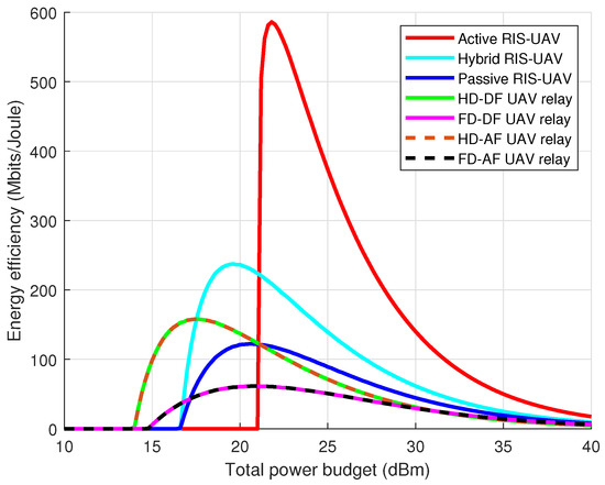
Figure 6.
Energy efficiency versus total power budget.
The full-duplex UAV relays, however, are always the least energy-efficient relaying scheme due to the limitation of their residual self-interference. Moreover, it can be observed that the energy efficiency of the AF UAV relays is similar to the DF UAV relays because both relaying schemes are experiencing weak channel links between the BS and the UAV relay. Nonetheless, the energy efficiencies of all the relaying schemes decrease gradually once the total power budget is sufficient to transmit the signals because the energy efficiency is the ratio of the achievable rate to the total power consumption.
4. Conclusions
The integration of RIS and UAVs has been envisaged as a new promising technology for beyond-5G networks. Therefore, this paper has investigated the performance of various relaying schemes and demonstrated that the proposed active and hybrid RIS-UAVs are better options than a passive RIS-UAV to assist ground communication. Based on the results simulated, active and hybrid RIS-UAVs, which amplify the signal while reflecting it to the UE, can overcome the double path-loss problem suffered by the passive RIS-UAV. The results numerically show that the proposed active and hybrid RIS-UAV schemes can provide up to 26 times and 14 times improvement in the energy efficiency as compared to the passive RIS-UAV, respectively, when the UAV is placed in the middle between the BS and UE. Meanwhile, when the UAV is placed close to the BS or UE, the performances of the proposed active and hybrid RIS-UAVs are about 187% and 18.9% higher than the passive RIS-UAV, respectively. Even though the energy efficiency of the existing passive RIS-UAV increases as the altitude of the UAV increases, the proposed active and hybrid RIS-UAVs still outperform it. In addition, the proposed active and hybrid RIS-UAVs can provide a high energy efficiency to the system even with a small number of total elements. By increasing the active elements of the hybrid RIS-UAV, the proposed hybrid RIS-UAV can double or triple the energy efficiency of the passive RIS-UAV. On the other hand, when compared to the conventional half-duplex UAV relays that require two phases to transmit signals, and the full-duplex UAV relays that are significantly affected by residual self-interference, the proposed active and hybrid RIS-UAVs show their superiority.
Even though an active RIS-UAV provides a higher energy efficiency than a hybrid RIS-UAV in most cases, it requires a larger power budget in order to supply the hardware components and circuits. Considering the limitation of the power budget of the UAV, the hybrid RIS-UAV is hence preferred as it requires lesser power to operate, such that the hybrid RIS-UAV can save up to 5 dBm while achieving an acceptable energy efficiency. Additionally, the hybrid RIS-UAV can be modified to become a passive RIS-UAV or an active RIS-UAV by dynamically adjusting its number of active elements based on the available power budget and the system requirements. Therefore, the application of a hybrid RIS-UAV in assisting the communication between the source and destination is a potential future work. In addition, the optimal altitude of the UAV and the number of total reflecting elements are worth to study for improving the performance of the hybrid RIS-UAV scheme.
Author Contributions
Conceptualization, C.Y.G. and C.Y.L.; methodology, C.Y.G. and C.Y.L.; software, C.Y.G. and C.Y.L.; validation, C.Y.G. and C.Y.L.; formal analysis, C.Y.G., C.Y.L. and R.N.; investigation, C.Y.G., C.Y.L. and R.N.; resources, C.Y.G. and C.Y.L.; data curation, C.Y.G. and C.Y.L.; writing—original draft preparation, C.Y.G.; writing—review and editing, C.Y.G., C.Y.L. and R.N.; visualization, C.Y.G. and C.Y.L.; supervision, C.Y.L.; project administration, C.Y.L.; funding acquisition, C.Y.L. All authors have read and agreed to the published version of the manuscript.
Funding
This work was supported in part by the Ministry of Higher Education Malaysia under the Fundamental Research Grant Scheme FRGS/1/2020/TK0/UTM/02/68, in part by H2020-MSCA-RISE-2020 under Grant 101008085, and in part by Universiti Teknologi Malaysia under Grant 08G83, Grant 22H33, and Grant 05E07.
Institutional Review Board Statement
Not applicable.
Informed Consent Statement
Not applicable.
Data Availability Statement
Not applicable.
Conflicts of Interest
The authors declare no conflict of interest.
Appendix A
Table A1.
Definition of Parameters Part I.
Table A1.
Definition of Parameters Part I.
| Parameter | Definition |
|---|---|
| Distance between the BS and the UAV | |
| Distance between the UAV and the UE | |
| Elevation angle between the BS and UAV | |
| Elevation angle between the UAV and UE | |
| a, b | Constant environmental parameters |
| Probability of LoS | |
| Probability of non-LoS | |
| Channel gains between the BS and the UAV | |
| Channel gains between the UAV and the UE | |
| A | Constant that represents the effect of the antenna gain and operating frequency |
| , | Independent and identically distributed (i.i.d) random variables that follow a Rician distribution |
| Aerial path-loss exponent for the link between BS and UAV | |
| Aerial path-loss exponent for the link between UAV and UE | |
| System operating frequency | |
| c | Speed of light |
| Rician factor | |
| Minimum Rician factor | |
| Maximum Rician factor | |
| , | Constant values based on the probability of LoS and NLoS |
| s | Information signal transmitted by the BS |
| Noise power at the active elements and UE | |
| Residual self-interference | |
| Reflection matrix of the active RIS-UAV | |
| Reflection matrix of active elements of the hybrid RIS-UAV | |
| Reflection matrix of passive elements of the hybrid RIS-UAV | |
| Reflection matrix of the passive RIS-UAV | |
| Index set that denotes the positions of active elements in hybrid RIS-UAV | |
| Amplification factor of the -th RIS element | |
| Phase shift of the -th RIS element | |
| Amplification gain of the RIS-UAV | |
| Amplification factor of the half-duplex AF UAV relay | |
| Amplification factor of the full-duplex AF UAV relay | |
| Total number of RIS elements | |
| L | Number of active elements in hybrid RIS-UAV |
| B | System bandwidth |
| Transmit power at the BS for the active RIS-UAV relaying scheme | |
| Transmit power at the BS for the hybrid RIS-UAV relaying scheme | |
| Transmit power at the BS for the passive RIS-UAV relaying scheme | |
| Transmit power at the BS for the half-duplex UAV relaying scheme | |
| Transmit power at the BS for the full-duplex UAV relaying scheme |
Table A2.
Definition of Parameters Part II.
Table A2.
Definition of Parameters Part II.
| Parameter | Definition |
|---|---|
| Transmit power of the active RIS-UAV | |
| Transmit power of the hybrid RIS-UAV | |
| Transmit power of the half-duplex UAV relays | |
| Transmit power of the full-duplex UAV relays | |
| Total power consumption | |
| Power consumption of the control circuit and phase shift switch at each RIS elements | |
| Power consumption of direct current (DC) biasing at each active RIS element | |
| Hardware-dissipated power at the BS | |
| Hardware-dissipated power at the UE | |
| Hardware-dissipated power at the UAV relay |
References
- Mozaffari, M.; Saad, W.; Bennis, M.; Nam, Y.; Debbah, M. A Tutorial on UAVs for Wireless Networks: Applications, Challenges, and Open Problems. IEEE Commun. Surv. Tutorials 2019, 21, 2334–2360. [Google Scholar] [CrossRef]
- Zhang, S.; Zhang, H.; Song, L. Beyond D2D: Full Dimension UAV-to-Everything Communications in 6G. IEEE Trans. Veh. Technol. 2020, 69, 6592–6602. [Google Scholar] [CrossRef]
- Giordani, M.; Zorzi, M. Non-Terrestrial Networks in the 6G Era: Challenges and Opportunities. IEEE Netw. 2021, 35, 244–251. [Google Scholar] [CrossRef]
- Li, B.; Fei, Z.; Zhang, Y. UAV Communications for 5G and Beyond: Recent Advances and Future Trends. IEEE Internet Things J. 2019, 6, 2241–2263. [Google Scholar] [CrossRef]
- Zeng, Y.; Zhang, R.; Lim, T.J. Throughput Maximization for UAV-Enabled Mobile Relaying Systems. IEEE Trans. Commun. 2016, 64, 4983–4996. [Google Scholar] [CrossRef]
- Wu, Q.; Zhang, S.; Zheng, B.; You, C.; Zhang, R. Intelligent Reflecting Surface-Aided Wireless Communications: A Tutorial. IEEE Trans. Commun. 2021, 69, 3313–3351. [Google Scholar] [CrossRef]
- Munochiveyi, M.; Pogaku, A.C.; Do, D.; Le, A.; Voznák, M.; Nguyen, N.D. Reconfigurable Intelligent Surface Aided Multi-User Communications: State-of-the-Art Techniques and Open Issues. IEEE Access 2021, 9, 118584–118605. [Google Scholar] [CrossRef]
- Nguyen, N.T.; Vu, Q.D.; Lee, K.; Juntti, M. Hybrid Relay-Reflecting Intelligent Surface-Assisted Wireless Communications. IEEE Trans. Veh. Technol. 2022, 71, 6228–6244. [Google Scholar] [CrossRef]
- Huang, C.; Zappone, A.; Alexandropoulos, G.C.; Debbah, M.; Yuen, C. Reconfigurable Intelligent Surfaces for Energy Efficiency in Wireless Communication. IEEE Trans. Wirel. Commun. 2019, 18, 4157–4170. [Google Scholar] [CrossRef]
- Boulogeorgos, A.A.A.; Alexiou, A. Performance Analysis of Reconfigurable Intelligent Surface-Assisted Wireless Systems and Comparison With Relaying. IEEE Access 2020, 8, 94463–94483. [Google Scholar] [CrossRef]
- Renzo, M.D.; Ntontin, K.; Song, J.; Danufane, F.H.; Qian, X.; Lazarakis, F.; Rosny, J.D.; Phan-Huy, D.T.; Simeone, O.; Zhang, R.; et al. Reconfigurable Intelligent Surfaces vs. Relaying: Differences, Similarities, and Performance Comparison. IEEE Open J. Commun. Soc. 2020, 1, 798–807. [Google Scholar] [CrossRef]
- Björnson, E.; Özdogan, Ö.; Larsson, E.G. Intelligent Reflecting Surface Versus Decode-and-Forward: How Large Surfaces Are Needed to Beat Relaying? IEEE Wirel. Commun. Lett. 2020, 9, 244–248. [Google Scholar] [CrossRef]
- Pogaku, A.C.; Do, D.T.; Lee, B.M.; Nguyen, N.D. UAV-Assisted RIS for Future Wireless Communications: A Survey on Optimization and Performance Analysis. IEEE Access 2022, 10, 16320–16336. [Google Scholar] [CrossRef]
- Park, K.W.; Kim, H.M.; Shin, O.S. A Survey on Intelligent-Reflecting-Surface-Assisted UAV Communications. Energies 2022, 15, 5143. [Google Scholar] [CrossRef]
- Pang, X.; Sheng, M.; Zhao, N.; Tang, J.; Niyato, D.; Wong, K. When UAV Meets IRS: Expanding Air-Ground Networks via Passive Reflection. IEEE Wirel. Commun. 2021, 28, 164–170. [Google Scholar] [CrossRef]
- Wang, D.; Zhao, Y.; He, Y.; Tang, X.; Li, L.; Zhang, R.; Zhai, D. Passive Beamforming and Trajectory Optimization for Reconfigurable Intelligent Surface-Assisted UAV Secure Communication. Remote Sens. 2021, 13, 4286. [Google Scholar] [CrossRef]
- Shafique, T.; Tabassum, H.; Hossain, E. Optimization of Wireless Relaying With Flexible UAV-Borne Reflecting Surfaces. IEEE Trans. Commun. 2021, 69, 309–325. [Google Scholar] [CrossRef]
- Long, R.; Liang, Y.C.; Pei, Y.; Larsson, E.G. Active Reconfigurable Intelligent Surface-Aided Wireless Communications. IEEE Trans. Wirel. Commun. 2021, 20, 4962–4975. [Google Scholar] [CrossRef]
- Mohamed, Z.; Aïssa, S. Leveraging UAVs with Intelligent Reflecting Surfaces for Energy-Efficient Communications with Cell-Edge Users. In Proceedings of the 2020 IEEE International Conference on Communications Workshops (ICC Workshops), Dublin, Ireland, 7–11 June 2020; pp. 1–6. [Google Scholar]
- Mohamed, Z.; Aïssa, S. Resource Allocation for Energy-Efficient Cellular Communications via Aerial IRS. In Proceedings of the 2021 IEEE Wireless Communications and Networking Conference (WCNC), Nanjing, China, 29 March–1 April 2021; pp. 1–6. [Google Scholar]
- Li, Y.; Yin, C.; Do-Duy, T.; Masaracchia, A.; Duong, T.Q. Aerial Reconfigurable Intelligent Surface-Enabled URLLC UAV Systems. IEEE Access 2021, 9, 140248–140257. [Google Scholar] [CrossRef]
- Al-Jarrah, M.; Al-Dweik, A.; Alsusa, E.; Iraqi, Y.; Alouini, M.S. On the Performance of IRS-Assisted Multi-Layer UAV Communications With Imperfect Phase Compensation. IEEE Trans. Commun. 2021, 69, 8551–8568. [Google Scholar] [CrossRef]
- Al-Hourani, A.; Kandeepan, S.; Lardner, S. Optimal LAP Altitude for Maximum Coverage. IEEE Wirel. Commun. Lett. 2014, 3, 569–572. [Google Scholar] [CrossRef]
- Azari, M.M.; Rosas, F.; Chen, K.C.; Pollin, S. Ultra Reliable UAV Communication Using Altitude and Cooperation Diversity. IEEE Trans. Commun. 2018, 66, 330–344. [Google Scholar] [CrossRef]
- New, W.K.; Leow, C.Y.; Navaie, K.; Ding, Z. Robust Non-Orthogonal Multiple Access for Aerial and Ground Users. IEEE Trans. Wirel. Commun. 2020, 19, 4793–4805. [Google Scholar] [CrossRef]
- Zhi, K.; Pan, C.; Ren, H.; Chai, K.K.; Elkashlan, M. Active RIS Versus Passive RIS: Which is Superior With the Same Power Budget? IEEE Commun. Lett. 2022, 26, 1150–1154. [Google Scholar] [CrossRef]
- Dai, L.; Wang, B.; Wang, M.; Yang, X.; Tan, J.; Bi, S.; Xu, S.; Yang, F.; Chen, Z.; Renzo, M.D.; et al. Reconfigurable Intelligent Surface-Based Wireless Communications: Antenna Design, Prototyping, and Experimental Results. IEEE Access 2020, 8, 45913–45923. [Google Scholar] [CrossRef]


Disclaimer/Publisher’s Note: The statements, opinions and data contained in all publications are solely those of the individual author(s) and contributor(s) and not of MDPI and/or the editor(s). MDPI and/or the editor(s) disclaim responsibility for any injury to people or property resulting from any ideas, methods, instructions or products referred to in the content. |
© 2023 by the authors. Licensee MDPI, Basel, Switzerland. This article is an open access article distributed under the terms and conditions of the Creative Commons Attribution (CC BY) license (https://creativecommons.org/licenses/by/4.0/).