Abstract
In Republic of Korea, cracks in concrete structures are considered to be objective structural defects, and the constant maintenance of deteriorating facilities leads to substantial social costs. Thus, it is important to develop technologies that enable economical and efficient building safety inspection. Recently, the application of UAVs and deep learning is attracting attention for efficient safety inspection. However, the currently developed technology has limitations in defining structural cracks that can seriously affect the stability of buildings. This study proposes a method to define structural cracks on the outer wall of a concrete building by merging the orthoimage layer and the structural drawing layer with the UAV and deep learning that were previously applied during a safety inspection. First, we acquired data from UAV-based aerial photography and detected cracks through deep learning. Structural and non-structural cracks were defined using detected crack layer, design drawing layer defined the structural part, and the orthoimage layer was based on UAV images. According to the analysis results, 116 structural parts cracks and 149 non-structural parts cracks were defined out of a total of 265 cracks. In the future, the proposed method is expected to greatly contribute to safety inspections by being able to determine the quality and risk of cracks.
1. Introduction
Cracks inevitably occur in concrete structures. Various factors cause cracks, such as structural characteristics, negligence during construction, and deterioration. Neglected cracks may develop severely and impact structural stability [1]. Cracks in a concrete structure can cause critical losses, such as structural defects, degraded durability, exterior damage, rebar corrosion, and degraded waterproofing performance. Cracks sized at approximately 0.05–0.1 mm require attention. Cracks at approximately 0.3–0.4 mm are considered defects and can develop into dangerous sizes [2].
In Korea, concrete cracks are considered as an objective defect. To assess concrete cracks, the suitability for normal use is determined by considering general technical rules, such as construction-related laws [3]. Article 7 (Concrete Cracks) of the Standards for the Investigation, Repair Cost Estimation, and Judgment of Defects in Apartment Housing, established by the Ministry of Land, Infrastructure, and Transport (MOLIT), defines the defects of concrete cracks. According to this law, only cracks with a width of at least 0.3 mm are classified as defects; cracks less than 0.3 mm in width are classified as defects only for cracks accompanied by leaks, cracks in the length direction of rebars where the rebars are placed, and penetrating cracks [4]. Furthermore, Article 44 (Standards for Design and Execution of Constructions) of the Construction Technology Promotion Act and Article 65 (Design Standards of Concrete Structures (KDS 14 20 00)) of the Enforcement Decree of the Construction Technology Promotion Act, established by MOLIT, define the permissible crack widths of reinforced concrete structures as 0.4 mm and 0.3 mm in dry and wet environments, respectively [5]. Current technical rules in Korea (e.g., laws on determining crack defects) set standards primarily for safety and durability.
Statistical data indicate that the problem of deterioration is gradually receiving more attention, owing to the lengthened service life of concrete buildings. According to statistical data from MOLIT, the percentage of aged buildings in Korea increased from 29.0% in 2005 to 39.6% in 2022 [6]. Maintaining the function of old concrete buildings and structures is challenging because various physical and chemical factors cause them to deteriorate or corrode [7].
Korea is incurring substantial social costs in maintaining deteriorating facilities. Thus, developing technologies for an economical and efficient building safety inspection is necessary. Safety inspections of facilities in the country are currently performed through visual inspections by experienced inspectors. Crack information is among the most important damage information obtained through visual inspections because it directly reflects structural conditions [8]. Accordingly, damage information of facilities is regularly surveyed through visual inspections. However, conventional human-based visual inspections are time-consuming and costly. Moreover, detecting cracks accurately is difficult, and inspection results are subjective, owing to the variability in the experience and proficiency of the inspector, reducing reliability and objectivity [9].
To address the limitations of conventional visual inspections, researchers have studied unmanned aerial vehicle (UAV)-based structural crack detection technology with efficient mobility that can be installed with various sensors. Wang et al. [10] used the extended cascading classifier (ECC) method to detect cracks on the surface of a wind turbine based on UAV-taken images. Salaan et al. [11] developed a passive rotating spherical shell (PRSS) UAV to detect structural cracks based on UAV-taken images and used a next-generation-robots-for-social-infrastructure (NGRSI) system. Ali Akbar et al. [12] used a feature-detection algorithm method based on speeded-up robust features (SURFs) to detect structural cracks based on UAV-taken images. Kim et al. [13] used a deep-learning-based region with convolutional neural networks (R-CNNs) method to identify cracks in deteriorated concrete bridges. Oh et al. [14] used Sobel, Laplacian, and Canny algorithms and a UAV installed with an infrared camera to detect heat leakage and cracks in the exterior walls of buildings. Munawar et al. [15] used a deep-learning-based-convolutional-neural-networks (CNNs) method to detect cracks and assess damage to civil infrastructure. They evaluated performance using five types of CNN structures: guided filtering (GF), baseline (BN), deep crack BN, deep crack GF, and SegNet. Wu et al. [16] used a mask regional convolutional neural network (Mask-RCNN) method to detect defects, such as cracks in a water tower. In addition, active research is being conducted on the application of vision technology. Research on object detection, tracking, and localization using point cloud techniques, image stitching, and deep learning has been conducted [17,18,19]. These studies demonstrated the applicability of UAVs and deep learning for crack detection.
Building structure refers to the primary parts providing structural strength to safely support the design load acting on the building [20]. Distinguishing between structural and non-structural cracks is necessary for prioritizing repair and reinforcement activities efficiently. Structural cracks are cracks that have progressed toward or reached a stage where the structure or structural member cannot safely support the working load. Non-structural cracks are cracks that do not degrade structural safety but can degrade durability and usability [21]. Thus, in concrete buildings, the risk level of cracks occurring in the main structure (columns, beams, load-bearing walls, slabs, roofs, etc.) differs from that of cracks occurring in other parts. Therefore, it is important to prioritize according to the risk of cracking, and repair and reinforcement work should be carried out according to the priority. However, most studies related to cracks in concrete buildings using UAV and a deep learning focus on crack detection. Studies defining cracks using structural part definition layers based on building design drawings information are insufficient. Moreover, currently developed technology has limitations in defining structural cracks that can seriously affect the stability of buildings.
Therefore, repair and reinforcement activities should be prioritized for cracks in the main structure. Most studies on cracks in concrete structures using UAV and deep learning focused on detection and location determination. Moreover, research on risk level according to the crack location is limited. This study proposes a method to define structural cracks on the outer wall of a concrete building by merging the orthoimage layer and the structural drawing layer with the UAV and deep learning that are previously applied during safety inspection. The purpose of this study is to provide a methodology for defining structural and non-structural cracks by utilizing technologies, such as information in UAV images, point cloud technology, structural analysis of design drawings, and merging layers (design drawings, orthoimages, and deep-learning-based crack detection images).
2. Proposed Method
This section explains the proposed method for defining structural cracks in the exterior walls of concrete buildings using a UAV, as shown in Figure 1. The proposed method comprises the following steps: (1) Acquire data: Drone-based aerial photography. (2) Detect cracks based on deep learning: (a) construct deep learning dataset and (b) detect cracks through deep learning. (3) Define structural cracks in the concrete building: (a) generate orthoimage based on point cloud technique and superimpose crack layer, (b) define the structure of exterior walls of the building using design drawings, and (c) define structural cracks through superimposed building crack expression data and design drawings.
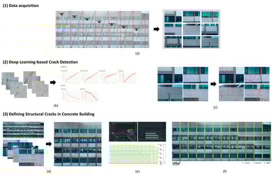
Figure 1.
Overview for defining structural cracks in the exterior walls of concrete buildings using a UAV: (a) Drone-based aerial photography; (b) construct deep learning dataset; (c) detect cracks through deep learning; (d) generate orthoimage based on point cloud technique and superimpose crack layer; (e) define the structure of exterior walls of the building using design drawings; (f) define structural cracks through superimposed building crack expression data and design drawings.
2.1. Data Acquisition
When acquiring data through UAV-based aerial photography, a flight plan must be set after sufficiently considering the photography conditions. The quality of data acquired through aerial photography significantly affects deep learning and spatial information construction. Accordingly, the flight plan in this study was established considering flight safety and the quality of the photographed data.
Before starting a flight using a UAV, the pilot must identify the factors affecting the flight and safety, including the structural system of the target building, layout of the surrounding terrain and buildings, and wire locations around the target building. Subsequently, a location without factors influencing flight and safety is selected, and aerial photography is performed. In photographing the building walls with a UAV, horizontal and vertical flights are used for changing the position and altitude of the UAV, respectively. Therefore, rotary-wing UAVs, which allow for hovering flight and can freely change altitude during flight, are more suitable than fixed-wing UAVs for aerial photography. Moreover, this study required close-up photography of the target building to acquire aerial images with cracks. A skilled pilot manually flew the UAV to handle unexpected situations with collision risks.
Considering the flight stability, data quality, and overlap of the acquired images is necessary for acquiring aerial photographs. The performance of the installed camera sensor and shooting distance affect the resolution of aerial images. Jeong et al. [22] used aerial images with a 12 MP resolution photographed from a distance of 5–10 m to detect cracks; however, the detection accuracy was low, and the range was limited. Liu et al. [23] used a UAV to detect cracks in a facility and acquired aerial images with 20.8 MP taken at a distance of 1–2 m. Kim and Cho [24] used a UAV for the automatic vision-based detection of cracks in concrete surfaces and acquired aerial images with a 20 MP resolution, taken at a distance of 2 m. Accordingly, this study aimed to obtain aerial images with a 20 MP resolution and set the shooting distance to 2 m considering safety.
Image overlap significantly affects spatial information construction based on the point cloud technique for defining the location of concrete cracks [25]. To detect cracks in deteriorated bridges, Ayele et al. [26] set the image overlap to 60–70% to construct spatial information. Zhu et al. [27] used aerial images with a 75% image overlap to detect road cracks based on deep learning. Yuhan Jiang et al. [28] set the image overlap to 50% to detect defects in buildings and infrastructure. Accordingly, this study set the image overlap to at least 65% for data acquisition to build spatial information and express concrete cracks.
2.2. Deep-Learning-Based Crack Detection
Detecting cracks based on deep learning involves two processes: (a) constructing a pretraining deep learning dataset and (b) detecting cracks through deep learning.
A pretraining dataset must first be constructed to detect cracks in concrete buildings based on deep learning. The quantity of data trained during dataset preparation significantly affects the model training and evaluation accuracy. This study used the SDNET2018 image dataset edited by Maguire et al. [29] for constructing the training dataset. SDNET2018 is an annotated image dataset for training, validating, and benchmarking AI-based algorithms for concrete crack detection. This dataset contains 56,000 images of bridge decks, walls, and roads. This study built a pretraining dataset of 12,500 images, comprising 6000 images with cracks and 6000 images without cracks selected from the SDNET2018 and 500 UAV-obtained aerial images with cracks.
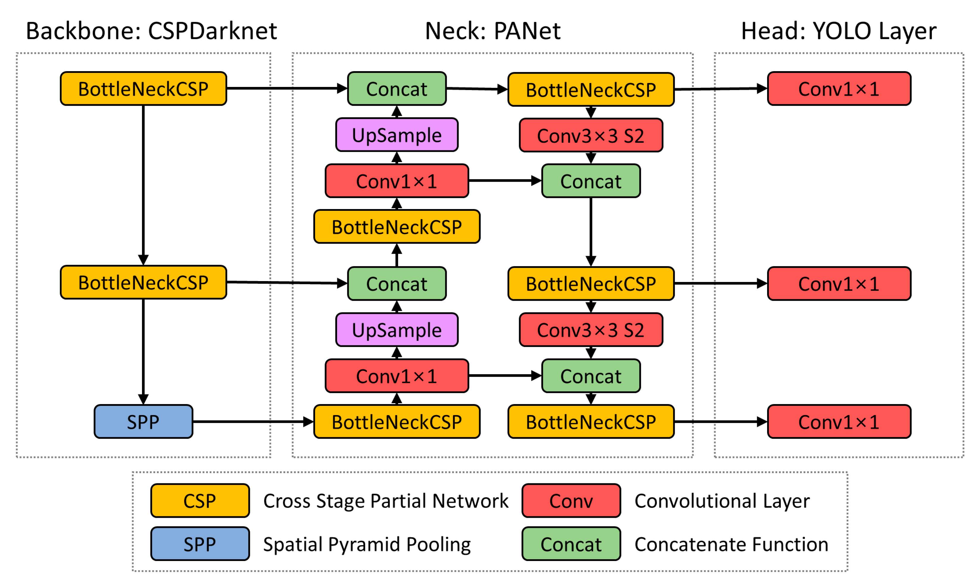
Subsequently, cracks in concrete buildings were detected using the YOLO V5 model, the latest object detection algorithm in the you-only-look-once (YOLO) product group. YOLO V5 is a machine learning algorithm with high processing speed and accuracy applicable for crack detection [30]. Figure 2 shows the architectural composition of YOLO V5.

Figure 2.
Architectural composition of YOLO V5.
The YOLO V5 architecture comprises a backbone (CSPDarknet), neck (PANet), and head (YOLO Layer), among which the backbone processes feature extraction at various levels in the cross-stage partial (CSP) network. Subsequently, BottleNeck formulates the image function and transfers it to the neck (PANet) and special pyramid pooling (SPP). The neck contains a series of connected BottleNeckCSPs and circuit networks. In the final step, the head uses a series of convolutional networks to combine the image features and process prediction boxes and their classes. The prediction box localization is based on an object-tracking algorithm that iteratively modifies the location of the bounding boxes [31]. This process significantly increases the efficiency of the YOLO V5 algorithm and makes it usable for crack detection in buildings.
2.3. Defining Structural Cracks in Concrete Building
Defining structural cracks in concrete buildings comprises three steps: (a) generate orthoimage based on point cloud technique and superimpose crack layer, (b) define the structure of exterior walls of building using design drawings, and (c) define structural cracks through superimposed building crack expression data and design drawings.
Spatial information of the UAV-acquired aerial images must first be built to generate an orthoimage to express building cracks. The point cloud technique can be applied to UAV-based aerial images to build spatial information. Spatial information construction based on the point cloud technique comprises three steps: (1) initial processing, (2) point cloud and mesh, and (3) digital surface model (DSM) and orthoimages. First, feature points are identified as key points in images, containing location information using the scale-invariant feature transform (SIFT) algorithm. Subsequently, images with the same feature points are searched and matched, and the internal and external parameters of the photographing sensor are corrected. Thereafter, a point cloud is constructed through point densification of the generated feature points. A 3D textured mesh can be generated based on the constructed point cloud. A 3D model can be established through this process. A DSM and an orthoimage can be generated based on the 3D model [32]. In segmenting and reconstructing the aerial images in points to create the 3D model, the image quality in the orthoimage generated based on the point cloud technique deteriorates compared with the raw data [33]. Consequently, millimeter-level crack detection is limited in orthoimages created based on the point cloud technique. In Section 2.2, the detected crack layer of the building was manually matched with the orthoimage using deep learning to construct superimposed orthoimage data expressing the building cracks. Subsequently, the structure of the exterior walls of the building was defined using design drawings. The size and position of the structural members were defined using the floor plan, elevation, sectional view, and structural drawings of the target building. Moreover, according to Article 2, Item 7 of the Korean Building Act, the main structure was defined as columns, beams, slabs, and load-bearing walls. The main structure and non-structural members were classified based on the design drawings. Subsequently, the building crack expression data were established by superimposing the elevation of the target building on the orthoimage data expressing the locations of the point-cloud-based cracks. The locations of structural cracks were defined based on these constructed building crack expression data. This study performed a comparative analysis with the location information values of cracks in real buildings using measuring equipment to verify the classified cracks.
3. Experiment
3.1. Data Acquisition
The model Phantom4 RTK from the Chinese company DJI was selected as the UAV for aerial photography. Phantom4 RTK is a rotary-wing drone with a camera sensor and real-time kinematic (RTK) receiver, enabling high accuracy, even when the position of the UAV cannot be corrected. The UAV used in this study had a vertical and horizontal accuracy of ±0.1 m when hovering and can detect surrounding obstacles from 0.7–30 m. It uses a 1” CMOS camera sensor with a 20 MP resolution and is equipped with a mechanical shutter to eliminate the risk of rolling shutter distortion during UAV motion.
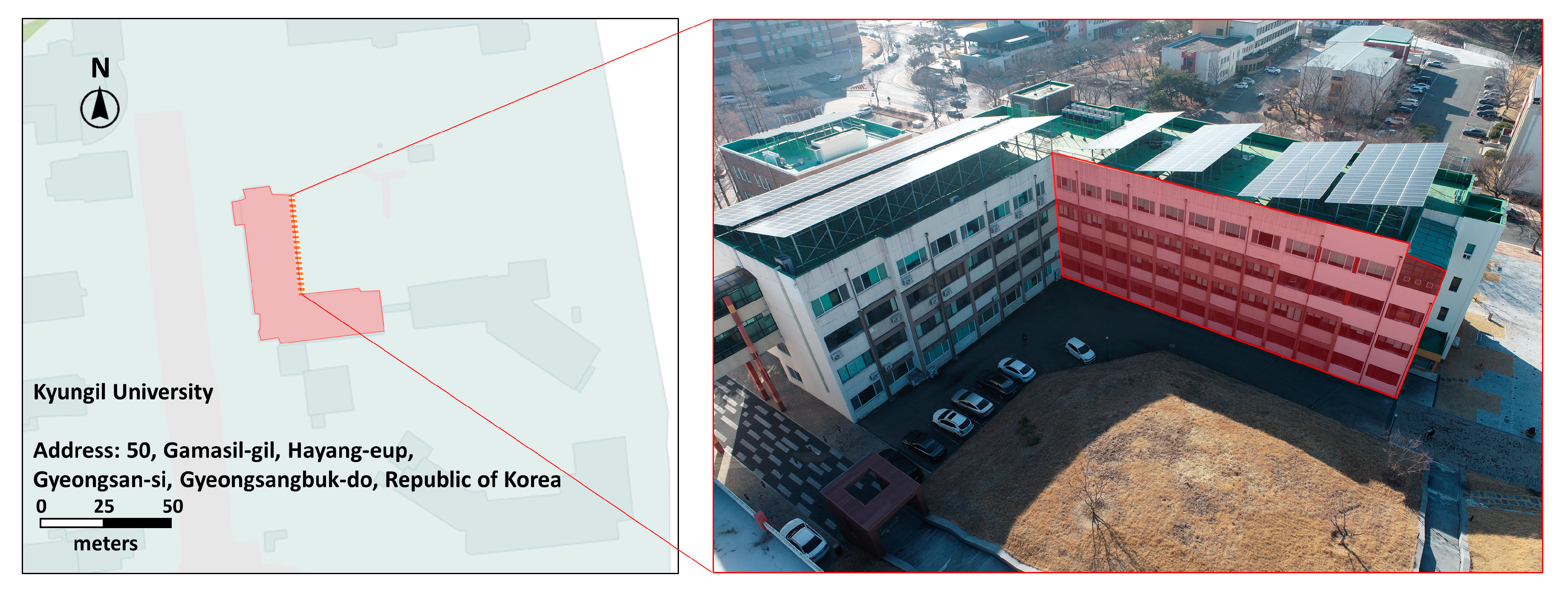
A target site was selected to verify the proposed method. The target site was a concrete building of Kyungil University in Gyeongsan-si, Gyeongsangbuk-do, Korea. The proposed crack detection process was possible because cracks were identified in the exterior of the building. Moreover, this building was suitable for the proposed research method because the cracks were distributed throughout the structural and non-structural parts of the building. Figure 3 shows an overview of the target site where the aerial photography was performed.
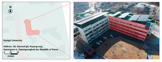
Figure 3.
Overview of the target site.
The UAV-based aerial photography was performed through manual flight in a single-grid format of the exterior of the target building on 10 December 2022. The 44 min flight yielded 647 images (ISO-100, aperture F/4, shutter speed 1/120 s, shooting angle 0°). The angle between the building exterior and camera sensor was set to perpendicular, and the shooting distance was set to 2 m, according to the literature review in Section 2.1. Although obtaining aerial photographs with uniform image overlap through manual flight is challenging, aerial photographs with image overlap of at least 65% were obtained. The ground sample distance (GSD) of the aerial images was found to be 0.16 cm/pixel, indicating their usability for crack detection.
3.2. Deep-Learning-Based Crack Detection
After taking aerial images of the exterior walls of the concrete building, a deep-learning-based object detection method was used to detect and identify cracks. Based on the collected SDNET2018 images and UAV-acquired dataset of 500 crack images, 12,500 images (12,500 data, 1 class) were divided into sets for crack detection training, validation, and testing, as shown in Table 1. The selection of only 12,000 images from the SDNET2018 dataset was made for practical reasons, such as reducing processing time or limited computational resources.

Table 1.
Dataset ratio.
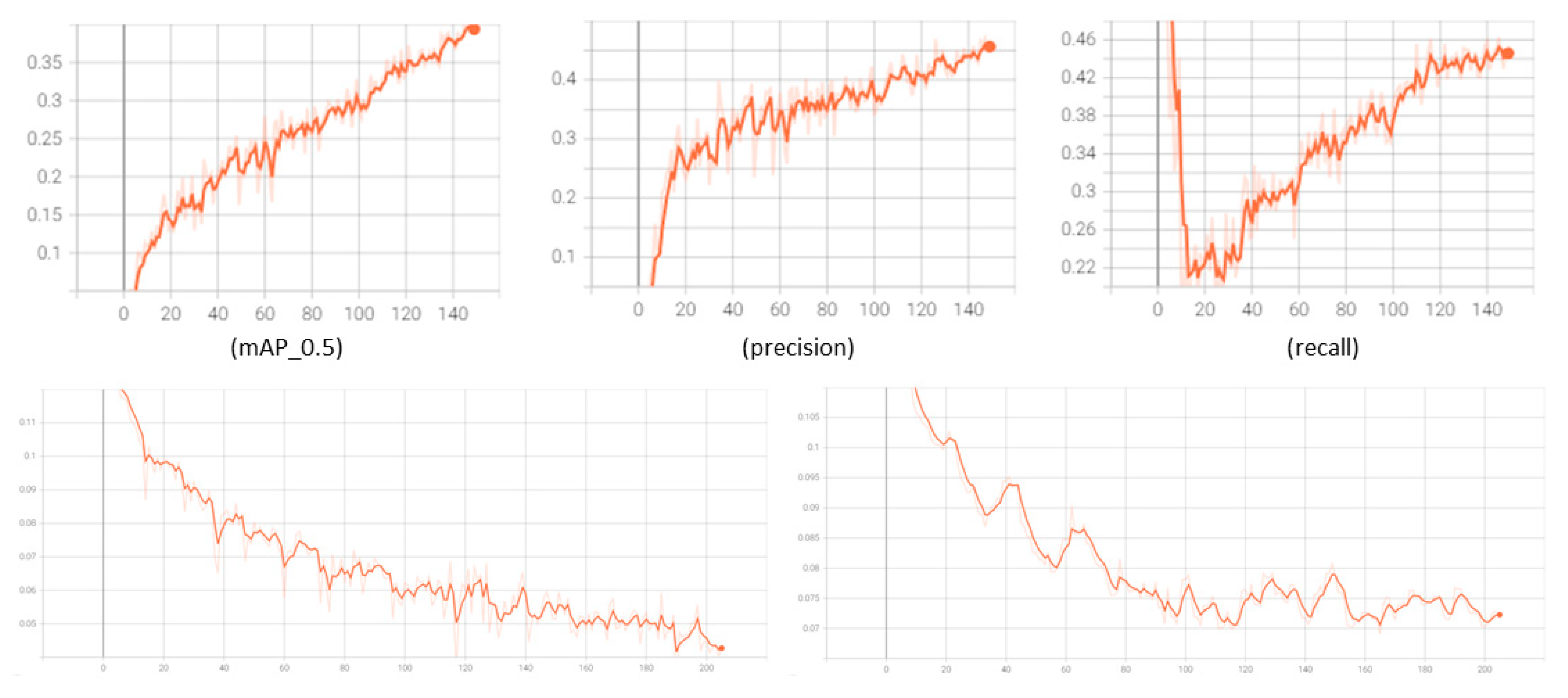
Subsequently, the model was trained with a batch size of 16 and 150 epochs. Figure 4 shows the mean Average Precision (mAP), precision, recall, train_loss, and validation_loss values obtained through training. mAP (mean average precision) is obtained by obtaining one AP value per object and obtaining the average value of AP for each class. Further, YOLO V5 uses the sum-squared error between the predicted value and the actual value to calculate the loss, which is represented by box_loss and obj_loss.
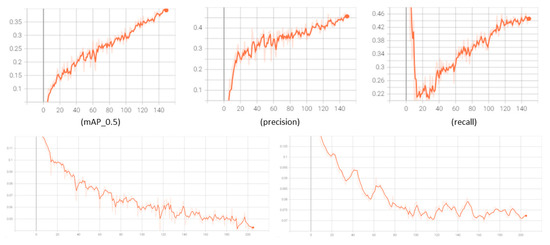
Figure 4.
Training result of dataset.
As shown in the figure, it was confirmed that the loss function is decreasing and overfitting does not occur. Further, since the learning results are converging to a certain level, additional epochs are not considered. Therefore, crack detection was performed to create an orthoimage-based crack layer using the training model.
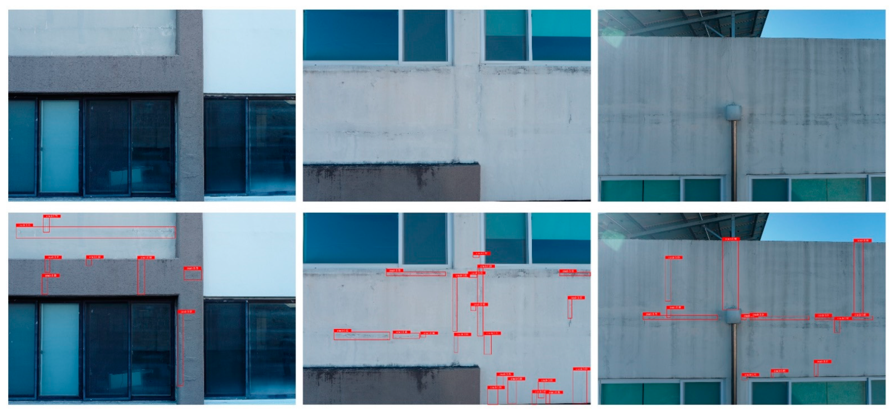
Crack detection was performed on 647 aerial images, and 265 cracks were detected. Figure 5 shows the crack detection results.

Figure 5.
Results of crack detection.
3.3. Defining Structural Cracks in Concrete Building
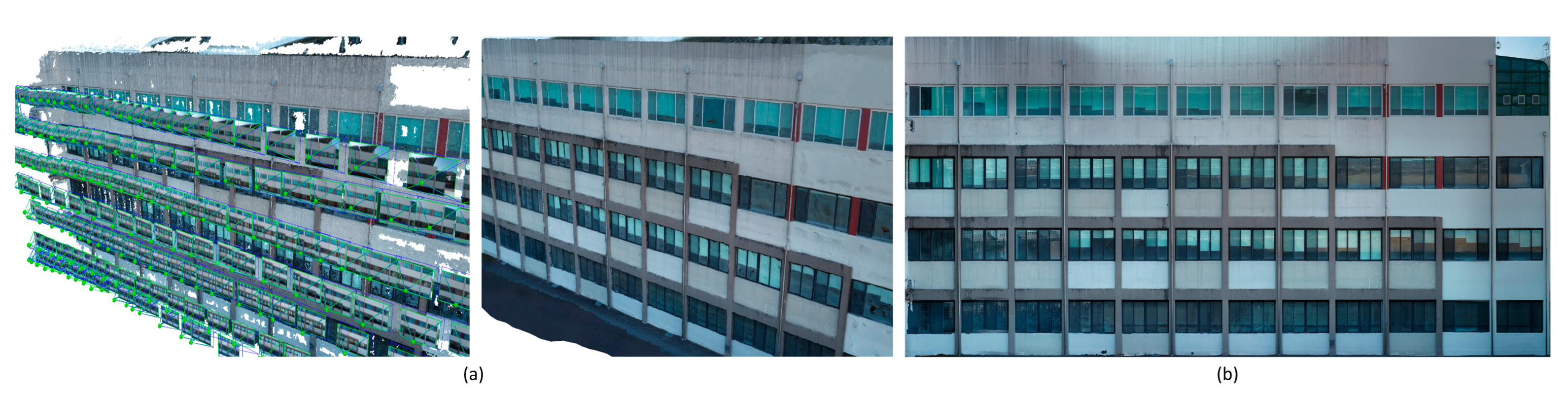
This study generated a 3D point cloud model of the building based on the obtained aerial images. PIX4Dmapper from Swiss company PIX4D was used to build the spatial information. Each aerial image was matched to create 20,073 tie points. Orthoimages were created with a GSD of 0.21 cm/pixel. Figure 6a shows the spatial information construction process of the building. Figure 6b shows the orthoimages generated to express the cracks.

Figure 6.
Process of spatial information construction. (a) Initial processing, point cloud, and mesh; (b) orthoimage.
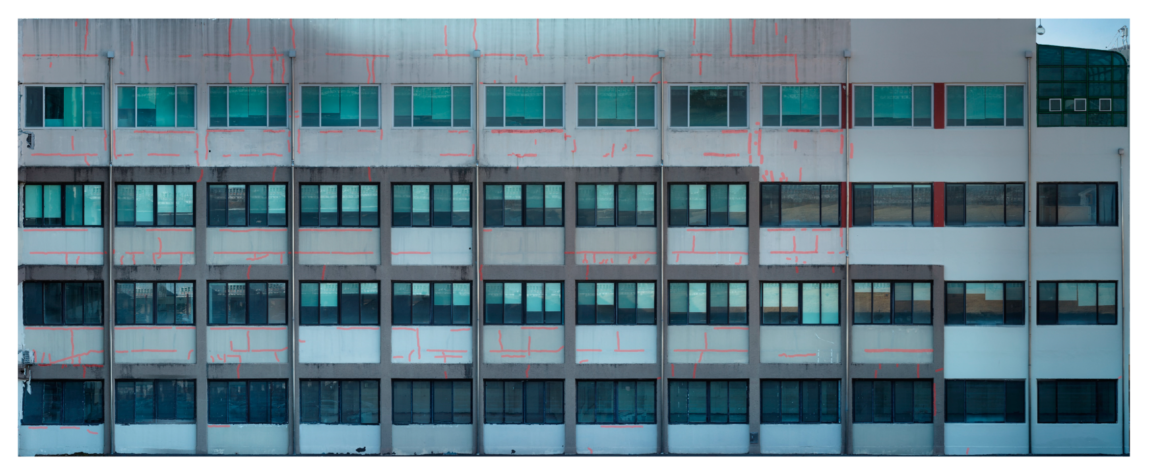
Construction of orthoimage-based crack layer defining structural and non-structural cracks was expressed based on the previously generated orthoimages in Figure 6b and the result of crack detection. The detected cracks were manually matched with the orthoimages, and 265 cracks were expressed in the orthoimages. Figure 7 shows the orthoimages expressing the crack locations detected in this study.
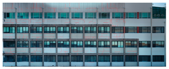
Figure 7.
Orthoimage with crack expression.
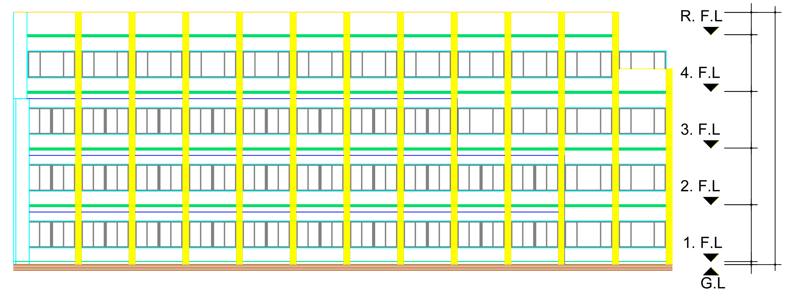
Using the design drawings, the exterior wall structure of the building was defined with the floor plan, elevation, sectional view, and structural drawings of the site. The structural members of the exterior walls of the building were defined using the floor plan, sectional view, and structural drawings. The locations of the structural parts in the exterior walls were defined using the floor plan and elevation. Figure 8 shows design drawings defining the locations of structural parts.
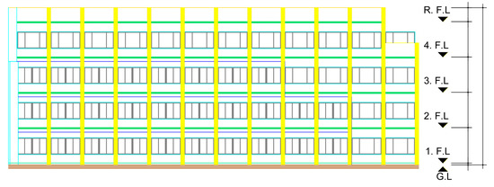
Figure 8.
Design drawings defining the locations of structural parts.
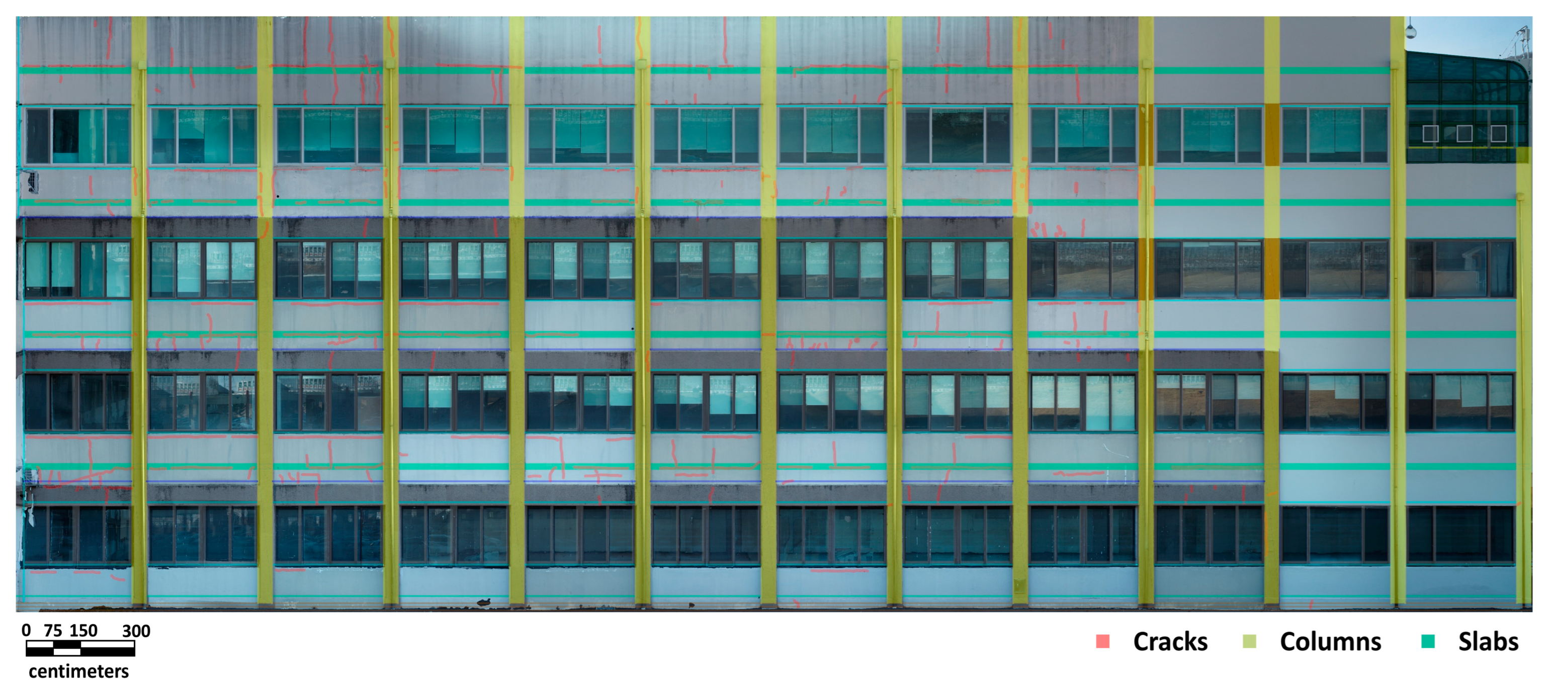
Subsequently, the orthoimages expressing the crack locations were superimposed with the design drawings defining the structural and non-structural parts of the target building to classify the crack locations. AutoCAD of the American company Autodesk was used for superimposing. The design drawings were converted to coordinates. The images were matched using the relative coordinates of the orthoimage data expressing the crack locations with the building design drawings containing coordinate values. First, the 1:200-scale design drawings and 1:1000-scale orthoimages were standardized. Subsequently, to superimpose the elevation of the target building with the orthoimages, the bottom-left starting point of the elevation was set as the reference point (0,0), the relative distance from the reference point was converted into (x,y) coordinates, and the relative location information was estimated. Figure 9 shows the constructed data expressing the building cracks.
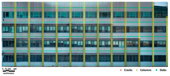
Figure 9.
Constructed data expressing the building cracks.
The crack definition was classified through merging of orthoimage-based crack layer and design drawing layer classified as structural and non-structural parts. The definitions of 265 cracks were classified, as shown in Table 2. Among the total of 265 cracks, there were 116 cracks in the structural part, 50 cracks in the column part, and 66 cracks in the slab part. In addition, there were 149 cracks in non-structural parts.
Table 2.
Definitions of classified cracks.
To verify the applicability of the methodology proposed in this study, the results in Table 2 and the on-site measurement data were compared and analyzed. In total, 261 cracks were measured through on-site measurements. Among the total 261 cracks, there were 115 cracks in the structural part, 49 cracks in the column part, and 66 cracks in the slab part. In addition, there were 146 cracks in non-structural parts. As a result of comparative analysis of the information of the cracks defined by the methodology proposed in this study and those measured through on-site measurements, it was confirmed that one information error occurred in the structural part and three information errors occurred in the non-structural parts. In the case of four information errors that appeared through comparative analysis, it was confirmed that they were not cracks, such as repaired crack traces and concrete contamination. Further, the occurrence of information errors was identified as false detections of deep learning when detecting cracks in the exterior walls of concrete buildings.
The proposed methodology in this study defined a total of 116 structural cracks. On-site measurements confirmed the existence of 115 cracks and one crack trace in the structural part. The purpose of this study is not to develop or improve deep learning algorithms for crack detection. Instead, the purpose is to define structural and non-structural cracks by merging detected crack layer, design drawing layer defining the structural part, and the orthoimage layer based on UAV images. Therefore, this study is judged to be useful in that the 116 cracks detected in this study were accurately detected in the form of cracks (crack and traces of cracks).
4. Discussion
This study used a UAV and deep learning to define structural cracks in the exterior walls of a concrete building. When using UAVs for safety diagnosis, objective data can be acquired in places difficult for human access. Moreover, with deep learning, the acquired data can be analyzed objectively and accurately without human intervention. Owing to these advantages, many studies on applying deep learning and UAVs for the safety inspection of buildings and other facilities have been conducted. However, current studies focused only on detecting the occurrence of damage (e.g., Kim et al. [34]) or estimating the crack locations (e.g., Baek et al. [9]).
This study applied UAVs and deep learning, technologies recently gaining attention for safety inspection, to define structural cracks that can severely threaten building safety. The purpose of this study is to provide a methodology for defining structural and non-structural cracks by utilizing technologies, such as location information of UAV images, point cloud technology, structural analysis of design drawings, and merging layers (design drawings, orthoimages, and deep-learning-based crack detection images). This study is different from previous studies in that it defines structural cracks by utilizing the crack layer and orthoimage layer processed from drone images and the structure definition layer processed from building design drawings. Moreover, this study differs from previous research in that it provides a method for judging the quality and risk level of cracks. In addition, this method defines the structural and non-structural parts of the outer wall of a concrete building and expresses cracks by merging layers of design drawings, orthoimages, and deep-learning-based crack detection images. It is judged that this can be used as basic data to determine the quality and risk of cracks using UAVs. Furthermore, the proposed method is expected to greatly contribute to facility safety inspections by being able to determine the quality and risk of cracks, along with drones and deep learning that have been attracting attention during safety inspections.
However, applying the proposed method to old buildings with no design information is challenging because the structural and non-structural parts are distinguished based on design information. Many recent studies on extracting design information using drones have been conducted, such as the study of Baek et al. [35]. A technology that defines structural and non-structural parts in the design information constructed by drones can be integrated with the proposed method to increase the utilization of drones and deep learning in safety inspections.
Another limitation is that this study only classified the risk of structural and non-structural parts based on location. Quantitatively analyzing the risk of cracks occurring in structural parts should be explored in future works. A technology that quantitatively analyzes the impact on building safety according to structural and non-structural parts and crack location can be integrated with the proposed method to increase the utilization of drones and deep learning in safety inspections.
Many studies (e.g., Muhammad Ali Akbar et al. (2019)) on detecting damage in facilities using deep learning and drone technology have been conducted [12,13,14,15]. Integrating the proposed method with damage detection technologies in the future can significantly contribute to facility safety inspections. Moreover, the proposed method can be used for judging the quality and risk level of cracks using drones.
5. Conclusions
This study proposed a method to define structural cracks on the outer wall of a concrete building by merging the orthoimage layer and the structural drawing layer with the UAV and deep learning that were previously applied during safety inspection. The expressed crack location information was compared with measured values to verify the accuracy of the defined crack locations.
Orthoimages with a 0.21 cm/pixel GSD spatial resolution were created using 647 aerial images obtained with a UAV. The images were manually matched to express 265 cracks detected based on the YOLO V5 model in the orthoimages. To define the crack locations in the constructed orthoimages expressing the crack information, the structural parts were defined using the design drawings, and the relative location information was estimated to superimpose the images. Structural and non-structural cracks were defined using detected crack layer, design drawing layer defined the structural part, and the orthoimage layer based on UAV images.
Author Contributions
Conceptualization, H.-J.W. and S.-C.B.; methodology, H.-J.W. and S.-C.B.; software, H.-J.W.; validation, H.-J.W., J.O. and S.-C.B.; formal analysis, W.-H.H.; investigation, H.-J.W.; resources, J.O. and S.-C.B.; data curation, H.-J.W. and J.O.; writing—original draft preparation, H.-J.W.; writing—review and editing, S.-C.B.; visualization, J.O.; supervision, W.-H.H. and S.-C.B.; project administration, H.-J.W. and S.-C.B.; funding acquisition, J.O. All authors have read and agreed to the published version of the manuscript.
Funding
This work was supported by the National Research Foundation of Korea (NRF), grant funded by the Korea government (MSIT) (No. 2021R1A2C1095145).
Conflicts of Interest
The authors declare no conflict of interest.
References
- Ali, R.; Chuah, J.H.; Talip, M.S.A.; Mokhtar, N.; Shoaib, M.A. Structural Crack Detection using Deep Convolutional Neural Networks. Autom. Constr. 2022, 133, 103989. [Google Scholar] [CrossRef]
- Yao, Y.; Tung, S.E.; Glisic, B. Crack Detection and Characterization techniques—An Overview. Struct. Control Health Monit. 2014, 21, 1387–1413. [Google Scholar] [CrossRef]
- Yoon, J.Y. Construction Dispute Relations Act, 7th ed.Sa, P.Y., Ed.; PAKYOUNGSA: Republic of Korea, 2018; pp. 291–298, 818–819. [Google Scholar]
- No.2021-1262; Investigation of Defects in Apartment Houses, Calculation of Repair Costs and Standards for Determining Defects. Ministry of Land, Infrastructure and Transport, MOLIT Notification: Republic of Korea, 2022. Available online: https://www.law.go.kr/행정규칙/공동주택하자의조사,보수비용산정및하자판정기준/ (accessed on 16 January 2023).
- Concrete Standard Specification. Ministry of Land, Infrastructure and Transport; MOLIT Specification: Republic of Korea, 2022; Available online: https://www.law.go.kr/LSW/admRulLsInfoP.do?admRulSeq=2100000214235 (accessed on 16 January 2023).
- Ministry of Land, Infrastructure and Transport, MOLIT Statistics System. 2023. Available online: http://stat.molit.go.kr/portal/cate/engStatListPopup.do (accessed on 16 January 2023).
- Park, J. Lightweighting for Repair Mortar with Crushed and Expanded Waste Glass Aggregates. Mag. RCR 2021, 16, 56–61. [Google Scholar]
- Lee, J.; Cho, J. Analysis of Safety Evaluation Guidelines for Practical Maintenance of Existing Concrete Structures. LHI J. Land Hous. Urban Aff. 2020, 11, 83–92. [Google Scholar]
- Woo, H.; Seo, D.; Kim, M.; Park, M.; Hong, W.; Baek, S. Localization of Cracks in Concrete Structures using an Unmanned Aerial Vehicle. Sensors 2022, 22, 6711. [Google Scholar] [CrossRef]
- Wang, L.; Zhang, Z. Automatic Detection of Wind Turbine Blade Surface Cracks Based on UAV-Taken Images. IEEE Trans. Ind. Electron. 2017, 64, 7293–7303. [Google Scholar] [CrossRef]
- Salaan, C.J.O.; Okada, Y.; Mizutani, S.; Ishii, T.; Koura, K.; Ohno, K.; Tadokoro, S. Close Visual Bridge Inspection using a UAV with a Passive Rotating Spherical Shell. J. Field Robot. 2018, 35, 850–867. [Google Scholar] [CrossRef]
- Akbar, M.A.; Qidwai, U.; Jahanshahi, M.R. An Evaluation of Image-based Structural Health Monitoring using Integrated Unmanned Aerial Vehicle Platform. Struct. Control Health Monit. 2019, 26, e2276. [Google Scholar] [CrossRef]
- Kim, I.; Jeon, H.; Baek, S.; Hong, W.; Jung, H. Application of Crack Identification Techniques for an Aging Concrete Bridge Inspection using an Unmanned Aerial Vehicle. Sensors 2018, 18, 1881. [Google Scholar] [CrossRef] [PubMed]
- Oh, S.; Ham, S.; Lee, S. Drone-Assisted Image Processing Scheme using Frame-Based Location Identification for Crack and Energy Loss Detection in Building Envelopes. Energies 2021, 14, 6359. [Google Scholar] [CrossRef]
- Munawar, H.S.; Ullah, F.; Heravi, A.; Thaheem, M.J.; Maqsoom, A. Inspecting Buildings using Drones and Computer Vision: A Machine Learning Approach to Detect Cracks and Damages. Drones 2021, 6, 5. [Google Scholar] [CrossRef]
- Wu, Z.Y.; Kalfarisi, R.; Kouyoumdjian, F.; Taelman, C. Applying Deep Convolutional Neural Network with 3D Reality Mesh Model for Water Tank Crack Detection and Evaluation. Urban Water J. 2020, 17, 682–695. [Google Scholar] [CrossRef]
- Tang, Y.; Zhu, M.; Chen, Z.; Wu, C.; Chen, B.; Li, C.; Li, L. Seismic Performance Evaluation of Recycled Aggregate Concrete-Filled Steel Tubular Columns with Field Strain Detected Via a Novel Mark-Free Vision Method. Structures 2022, 37, 426–441. [Google Scholar] [CrossRef]
- Que, Y.; Dai, Y.; Ji, X.; Leung, A.K.; Chen, Z.; Tang, Y.; Jiang, Z. Automatic Classification of Asphalt Pavement Cracks using a Novel Integrated Generative Adversarial Networks and Improved VGG Model. Eng. Struct. 2023, 277, 115406. [Google Scholar] [CrossRef]
- Seo, D.-M.; Woo, H.-J.; Kim, M.-S.; Hong, W.-H.; Kim, I.-H.; Baek, S.-C. Identification of Asbestos Slates in Buildings Based on Faster Region-Based Convolutional Neural Network (Faster R-CNN) and Drone-Based Aerial Imagery. Drones 2022, 6, 194. [Google Scholar] [CrossRef]
- No. 919; Regulations on Structural Standards, etc. of Buildings. Ministry of Land, Infrastructure and Transport, Ordinance of MOLIT: Republic of Korea, 2021. Available online: https://www.law.go.kr/법령/건축물의구조기준등에관한규칙 (accessed on 16 January 2023).
- Jung, S.; Lee, S.; Park, C.; Cho, S.; Yu, J. A Method for Detecting Concrete Cracks using Deep-Learning and Image Processing. J. Archit. Inst. Korea Struct. Constr. 2019, 35, 163–170. [Google Scholar]
- Jeong, D.; Lee, J.; Ju, Y. Photogrammetric Crack Detection Method in Building using Unmanned Aerial Vehicle. J. Archit. Inst. Korea Struct. Constr. 2019, 35, 11–19. [Google Scholar]
- Liu, Y.; Nie, X.; Fan, J.; Liu, X. Image-based Crack Assessment of Bridge Piers using Unmanned Aerial Vehicles and Three-dimensional Scene Reconstruction. Comput.-Aided Civ. Infrastruct. Eng. 2020, 35, 511–529. [Google Scholar] [CrossRef]
- Kim, B.; Cho, S. Automated Vision-Based Detection of Cracks on Concrete Surfaces using a Deep Learning Technique. Sensors 2018, 18, 3452. [Google Scholar] [CrossRef]
- Bang, S.; Kim, H.; Kim, H. UAV-Based Automatic Generation of High-Resolution Panorama at a Construction Site with a Focus on Preprocessing for Image Stitching. Autom. Constr. 2017, 84, 70–80. [Google Scholar] [CrossRef]
- Ayele, Y.Z.; Aliyari, M.; Griffiths, D.; Droguett, E.L. Automatic Crack Segmentation for UAV-Assisted Bridge Inspection. Energies 2020, 13, 6250. [Google Scholar] [CrossRef]
- Zhu, J.; Zhong, J.; Ma, T.; Huang, X.; Zhang, W.; Zhou, Y. Pavement Distress Detection using Convolutional Neural Networks with Images Captured Via UAV. Autom. Constr. 2022, 133, 103991. [Google Scholar] [CrossRef]
- Jiang, Y.; Han, S.; Bai, Y. Building and Infrastructure Defect Detection and Visualization using Drone and Deep Learning Technologies. J. Perform. Constr. Facil. 2021, 35, 04021092. [Google Scholar] [CrossRef]
- Maguire, M.; Dorafshan, S.; Thomas, R.J. SDNET2018: A Concrete Crack Image Dataset for Machine Learning Applications. Data Brief. 2018, 21, 1664–1668. [Google Scholar]
- Yaseen, M.U.; Anjum, A.; Rana, O.; Antonopoulos, N. Deep Learning Hyper-Parameter Optimization for Video Analytics in Clouds. IEEE Trans. Syst. Man Cybern. Syst. 2018, 49, 253–264. [Google Scholar] [CrossRef]
- Fang, Y.; Guo, X.; Chen, K.; Zhou, Z.; Ye, Q. Accurate and Automated Detection of Surface Knots on Sawn Timbers using YOLO-V5 Model. BioResources 2021, 16, 5390–5406. [Google Scholar] [CrossRef]
- Liao, Y.; Mohammadi, M.E.; Wood, R.L. Deep Learning Classification of 2D Orthomosaic Images and 3D Point Clouds for Post-Event Structural Damage Assessment. Drones 2020, 4, 24. [Google Scholar] [CrossRef]
- Zeybek, M.; Şanlıoğlu, İ. Point Cloud Filtering on UAV Based Point Cloud. Measurement 2019, 133, 99–111. [Google Scholar] [CrossRef]
- Kim, I.; Yoon, S.; Lee, J.H.; Jung, S.; Cho, S.; Jung, H. A Comparative Study of Bridge Inspection and Condition Assessment between Manpower and a UAS. Drones 2022, 6, 355. [Google Scholar] [CrossRef]
- Baek, S.; Hong, W. A Study on the Construction of a Background Model for Structure Appearance Examination Chart using UAV. In Proceedings of the 2017 World Congress on Advances in Structural Engineering and Mechanics (ASEM), Ilsan, Republic of Korea, 28 August–1 September 2017. [Google Scholar]

Disclaimer/Publisher’s Note: The statements, opinions and data contained in all publications are solely those of the individual author(s) and contributor(s) and not of MDPI and/or the editor(s). MDPI and/or the editor(s) disclaim responsibility for any injury to people or property resulting from any ideas, methods, instructions or products referred to in the content. |
© 2023 by the authors. Licensee MDPI, Basel, Switzerland. This article is an open access article distributed under the terms and conditions of the Creative Commons Attribution (CC BY) license (https://creativecommons.org/licenses/by/4.0/).