Abstract
Different from mobile ad hoc networks (MANETs) and vehicular ad hoc networks (VANETs), a flying ad hoc network (FANET) is a very low-density network where node topology changes rapidly and irregularly. These characteristics, the density, mobility, and speed of flight nodes, affect the performance of FANET. Furthermore, application scenarios and environmental settings could affect the performance of FANETs. In this paper, we analyzed the representative FANET protocols, AODV, DSDV, and OLSR, according to mobility models, SRWP, MP, RDPZ, EGM, and DPR, under the multi-UAV-based reconnaissance scenario. We evaluated them in terms of the number of nodes, network connectivity, mobility model’s reconnaissance rate, speed of nodes, and ground control station (GCS) location. As a result, we found that AODV showed the highest PDR performance (81%) with SRWP in multiple UAV-based reconnaissance scenarios. As for a mobility model under the consideration of reconnaissance rate, SRWP was excellent at 76%, and RDPZ and EGM mobility models were reasonable at 62% and 60%, respectively. We also made several interesting observations such as how when the number of nodes increases, the connectivity of the network increases, but the performance of the routing protocol decreases, and how the GCS location affects the PDR performance of the combination of routing protocols and mobility models.
1. Introduction
An ad hoc network is a wireless network of mobile nodes without using an existing network infrastructure. A flying ad hoc network (FANET) is an ad hoc network with aircraft as nodes. FANETs can be used for communication between unmanned aerial vehicles (UAVs) and a ground control station (GCS). The types of FANET can be classified according to the types of aircraft (e.g., rotary wing and fixed wing), because the speed of aircraft is different, which affects the topology of nodes in the network. The faster the nodes, the faster the network topology changes. The more nodes, the higher the density of the FANET is. For example, when the density of nodes is low, nodes frequently join and leave the network. Furthermore, the network topology changes regularly or irregularly according to mobility models. All of these characteristics of FANETs affect the performance of communication between UAVs and GCS.
When it comes to the FANET routing protocols, it is the most important to effectively maintain the FANET network topology in order to transmit packets from UAVs to GCS or vice versa. However, many factors, such as the density, mobility, speed of flight nodes, and GCS location, can affect the performance of FANET routing protocols. Therefore, there is no particular routing protocol that can be considered superior to others in all of FANET applications. Therefore, an appropriate routing protocol should be identified according to the scenarios and environments to which the FANET is applied.
Many studies have analyzed FANET routing protocols. However, as far as we know, most of the studies did not consider the scenarios and environments to which the FANET is applied. Many studies did not mention the mobility model, or used only simple mobility models such as random waypoints [1,2,3,4,5,6,7,8,9,10,11,12,13,14,15,16,17]. Three studies used two and four mobility models [18,19,20], but the studies did not consider specific FANET scenarios. The most similar works to ours are two studies that analyzed FANET routing protocols based on specific scenarios [21,22]. However, the study in [22] assumed different scenarios from ours. Only one study in [21] assumed a reconnaissance scenario like ours, but their experiment is based on a very particular circumstance that all of the nodes are connected to a satellite system, which differs from ours.
We assume the reconnaissance scenario, where UAVs should evenly reconnoiter the reconnaissance area. Meanwhile, the moving patterns of UAVs should be irregular so that the enemy must not be able to predict the movement of UAVs. With our assumed scenario, we analyze and evaluate three routing protocols (AODV, DSDV, and OLSR) with five mobility models (SRWP, RDPZ, DPR, EGM, and MP). It helps identify routing protocols and mobility models suitable for reconnaissance scenarios. We also evaluate combinations of routing protocols and mobility models under various conditions, such as the number, connectivity, and speed of nodes, and GCS location, so as to understand how the factors can affect the performance of transmitting packets from UAVs to GCS.
As a result, AODV showed the highest PDR performance in multiple UAV-based reconnaissance scenarios. In the combination of routing protocols and the mobility models, SRWP showed the highest PDR performance with AODV. RDPZ and EGM also showed reasonable performance under the consideration of the reconnaissance rate. We also observe interesting facts, as follows. First, even if network connectivity (i.e., density) increases, the performance of a routing protocol does not improve, rather degrades after at some point. Second, the GCS location affects the PDR performance of the combination of a routing protocol and a mobility model.
Our contributions are as follows. First, we defined a multi-UAV-based reconnaissance scenario to analyze routing protocols with mobility models. Second, based on the scenario, we analyzed fifteen combinations of three representative routing protocols (AODV, DSDV, and OLSR) with five reconnaissance mobility models (SRP, RDPZ, EGM, MP, and DPSR) in terms of PDR performance. Third, with consideration of a reconnaissance scenario, we measured the connectivity of nodes as well as the reconnaissance rate of a mobility model in our analysis. Based on these metrics, we could identify a protocol and a mobility model for the reconnaissance scenario. Last, for a fair evaluation of routing protocols, we developed and used our own mobility model simulator to generate the trace file of each mobility model. With the trace file, we could analyze each protocol under the same condition of a mobility model. Furthermore, the repeated simulation of the same trace file helped us to analyze the effect of node connectivity on the PDR performance of routing protocols and to analyze the effect of GCS location on the PDR performance of routing protocols.
This paper is organized as follows: Section 2 discusses the relevant studies and their limitations. Section 3 describes the routing protocols, mobility models, and a reconnaissance scenario. Section 4 describes research questions, experimental environment, performance parameters, and experimental procedures to evaluate routing protocols. Section 5 reports the experimental results. Section 6 discusses the additional metric, end-to-end delay, and an additional factor, speed of nodes. The section then summarizes all experimental results and other issues. Section 7 concludes the paper.
2. Related Work
Related studies have analyzed the performance of FANET routing protocols. We classify the studies into four groups. Group A specifies no mobility models [1,2,3,4,5,6,7]. Group B uses only one mobility model or one mobility model with a fixed one [8,9,10,11,12,13,14,15,16,17]. Group C uses several mobility models [18,19,20]. Group D analyzed routing protocols with specific scenarios [21,22]. Table 1 summarizes the related work.

Table 1.
Summary of the related work.
Group A analyzed routing protocols with no mobility models [1,2,3,4,5,6,7]. Garcia et al., Leonov et al., and Kumar et al. examined two protocols each, AODV and DSDV [3], AODV and OLSR [5], and AODV and LAR [7], respectively. Singh et al. and Rabahi et al. analyzed three protocols: AODV, DSDV, and OLSR [1,6]. Li et al. proposed the LEPR routing protocol based on AODV and compared the AODV, DSR, and LEPR routing protocols [2]. Nayyar et al. compared and analyzed six routing protocols: AODV, DSDV, DSR, OLSR, AOMDV, and HWMP [4]. In this group, most studies evaluated representative ad hoc routing protocols such as AODV, DSDV, and OLSR. However, no studies specified mobility models. As the performance of routing protocols will differ depending on mobility models, it is necessary to specify and analyze this information.
Group B analyzed routing protocols with only one mobility model [8,9,10,11,12,13,14,15,16,17]. Most of the studies used the random waypoint mobility model [8,9,10,11,12,13,14,15,16]. Leonov et al. analyzed the performance of AODV and OLSR routing protocols [10,11,12]. Leonov et al. initially analyzed the BeeAdHoc protocol as well [9]. Maistrenko et al. analyzed AODV, DSDV, DSR, and AntHocNet. [8]. Rahman et al. analyzed routing protocols considering two variables, node speed and network size [13]. Ema et al. analyzed three categories of proactive, reactive, and hybrid routing protocols [14]. Zhang et al. proposed a routing protocol called DC-OLSR that is applicable to heterogeneous dual-channel FANETs [15]. Tuli et al. proposed an optimized E-OLSR by adjusting parameters and compared its performance with existing routing protocols through simulation [16]. Guillen et al. analyzed routing protocol performance using 2.4 GHz and 5 GHz WiFi networks under real-world conditions [17]. Because those studies used only one mobility model, they could not demonstrate different protocol performances with different mobility models.
Group C analyzed routing protocols with various mobility models [18,19,20]. Singh et al. sought to optimize OLSR in FANETs rather than analyzing several routing protocols [18]. AlKhatieb et al. analyzed various routing protocols using the random waypoint, Manhattan Grid, Pursue, and SRCM mobility models [19]. Rahmani et al. proposed a fuzzy logic-based routing approach called OLSR+ and compared OLSR+ with OLSR and G-OLSR [20] Those studies analyzed the performance of routing protocols. However, those studies did not consider specific scenarios, while the performance of FANET routing protocols is affected by various factors embedded in the usage scenarios.
Group D analyzed routing protocols with specific scenarios [21,22]. However, their scenarios differ from ours. For example, Ahmed et al. evaluated a disaster scenario [22]. Sang et al. evaluated protocols based on battlefield reconnaissance missions [21]. Sang et al. focused on a very specific circumstance where all nodes are connected to the BeiDou satellite system. While their directions are in accordance with ours in the consideration of specific scenarios, their results did not address our research interests, what would be a desirable routing protocol and a mobility model for a reconnaissance scenario. Differently from theirs, we compare and analyze the performance of FANET routing protocols with various mobility models in multiple UAV-based reconnaissance scenarios.
3. FANET Routing Protocols, Mobility Models, and Reconnaissance Scenarios
Section 3 describes the FANET protocols, mobility models, and reconnaissance scenarios. Section 3.1 describes three routing protocols: Ad Hoc On-demand Distance Vector (AODV), Optimized Link State Routing Protocol (OLSR), and Destination Sequenced Distance Vector (DSDV). Section 3.2 describes five mobility models: Smooth Random Way Point (SRWP), Markov Process (MP), Enhanced Gauss–Markov (EGM), Distributed Pheromon Repel (DPR), and Random Destination with Partitioned Zone (RDPZ). Section 3.3 describes our reconnaissance scenario.
3.1. FANET Routing Protocol Descriptions
FANET routing protocols require different requirements from traditional ad hoc networks, such as low node density, high mobility, and frequent topology changes. It is difficult to design a FANET routing protocol by considering these characteristics. Researchers sought to design routing protocols suitable for FANETs. They extended existing MANET and VANET routing protocols [23,24,25] or designed new routing protocols [9,26,27]. These FANET routing protocols can be classified in several ways. For example, Oubbati et al. classified FANET routing protocols into three categories: topology-based, swarm-based, and position-based protocols in 2017 [28]. In 2019, they also classified FANET routing protocols into eight categories: topology-based, secure-based, bio-inspired, hierarchical-based, energy-based, heterogeneous-based, and position-based protocols and delay tolerant networks [29]. Lakew et al. classified routing protocols into four types: topology-based, geographic, hybrid (geographic and topology-based), and bio-inspired protocols [30]. Wheeb et al. classified topology-based routing protocols into four categories: proactive, reactive, hybrid, and static protocols [31]. Based on Wheeb et al. [31], we reviewed the basic topology-based routing protocols to identify the protocols for our reconnaissance scenario. We then selected AODV, DSDV, and OLSR from proactive and reactive routing protocols. Our intention was to analyze fundamental protocols for a reconnaissance scenario, because we believed that the analysis of the fundamental protocols could be a basis for designing an appropriate routing protocol for the target reconnaissance scenario.
Ad hoc On-demand Distance Vector (AODV) is a reactive routing protocol that searches for a route to a node only when there is a route request. When there is a route request from the source node, it broadcasts a route request (RREQ) to the neighbor nodes. The route request (RREQ) is propagated to neighbor nodes until the request arrives at the destination node. The intermediate node checks the sequence number and stores the reverse path to prevent a loop of the route. The destination node that has received the route request (RREQ) sends a route reply (RREP) to the source node by referring to the reverse path stored in the neighboring node.
Destination Sequenced Distance Vector (DSDV) is a proactive routing protocol in which all the nodes composing a network are maintained in a routing table, either as direct paths between nodes or indirect paths formed through neighboring nodes. DSDV is a routing protocol based on the Bellman–Ford algorithm and prevents a loop using sequence numbers. DSDV updates the table using two mechanisms: an update is either initiated by a trigger or occurs on a regular basis. When a node’s routing table is changed, an update is triggered. A regular update occurs at specific intervals and broadcasts the entire routing table from a node to neighbor nodes.
Optimized Link State Routing Protocol (OLSR) is a protocol that compensates for the shortcomings of a proactive routing protocol, which sends and receives many messages to manage a routing table. To reduce the number of messages, OLSR uses a multipoint relay (MPR) node. In the OLSR mechanism, the source node finds the neighbor node using the HELLO message and finally finds the node that is most connected to the neighbor nodes, called an MPR node. Only the MPR node can flood the control message. To manage the information of the nodes that constitute a network, OLSR uses topology control (TC) messages and MPR forwarding information.
3.2. Mobility Model Descriptions
In reconnaissance scenarios, UAVs need to move irregularly. If a UAV moves regularly, the enemy can easily predict the UAV path. Therefore, in a reconnaissance scenario, a mobility model is required to ensure irregular movement. In this section, we introduce five mobility models.
The random waypoint model has been used as a default model due to its simplicity [32]. In the model, a UAV randomly generates a new destination in the reconnaissance area and then flies to the destination. When a UAV reaches the destination, it repeats this process during a period of reconnaissance time. Smooth Random WayPoint (SRWP) operates in the same way as the random waypoint model. The difference is that it considers a smooth turn by considering the UAV speed [33].
The Markov Process model exhibits three types of mobility [34]. The three mobility decisions are left turn, straight ahead, and right turn. These decisions are determined probabilistically according to the current state. For example, if a UAV is currently turning left, the probability of continuing to turn left is 70%, and the probability of changing to go straight ahead is 30%. A right turn works in the same way. When a UAV is currently going straight, the probability of continuing to go straight is 80%, the probability of turning left is 10%, and the probability of turning right is 10%.
The Enhanced Gauss–Markov (EGM) model applies the Gauss–Markov model for UAV reconnaissance [35]. This model accounts for smooth movement within the reconnaissance area and a smooth turn in the border area. When a UAV approaches the border area, the UAV avoids a collision by changing the mean directional deviation as well as the mean variance in the directional deviation.
The Distributed Pheromone Repel (DPR) model was inspired by the pheromones of ants [34]. Ants share their local pheromone information and move toward areas with strong pheromones. The DPR model adopts the concept of ant movements but implements it in an opposite fashion. Since the DPR model is designed for reconnaissance, UAVs fly to areas with fewer pheromones. Each UAV has its own virtual map that accumulates the pheromone distribution and updates its map by communicating with nearby nodes.
The Random Destination with Partitioned Zone (RDPZ) model reconnoiters by communicating with each UAV [36]. The RDPZ model divides the reconnaissance area into n * n zones and manages the number of reconnoitered destinations in each zone by communicating with the nearby UAVs. When a UAV flies to a destination, the UAV stochastically chooses the intermediate zone with fewer destinations.
3.3. Reconnaissance Scenarios
A reconnaissance scenario is to discover an enemy in a targeted area. The enemy should have difficulty predicting the path of our UAVs. Therefore, UAVs should reconnoiter in an irregular route rather than a plan-based, regular route. Mobility models described in Section 3.2 helps to generate an irregular route for UAVs.
We suggest a reconnaissance scenario with multiple UAVs. Multiple UAVs can cover a larger reconnaissance area, as well as can help FANETs provide wider network coverage. In addition, the failure of a UAV does not cause a failure of the entire FANET network. In other words, multiple UAVs increase the redundancy and reliability of FANETs.
In our scenario, multiple UAVs reconnoiter a targeted area according to a reconnaissance mobility model. Once a UAV detects an enemy, the UAV should efficiently send the information of the detected enemy to GCS. In this scenario of sending information, other UAVs serve as communication nodes that transmit information to GCS. FANET protocols described in Section 3.1 help to transmit information from a UAV to GCS via several UAVs.
To be more specific in our scenario, we set up the following conditions. First, the GCS has a fixed position in the center of the reconnaissance area. Second, each UAV periodically sends packets to the GCS during its mission. Third, we assumed that the altitudes of UAVs are almost the same (We will discuss the altitude of UAVs in Section 6.4).
Based on the specific scenario, we conduct a routing protocol performance analysis. In our routing protocol performance analysis for the reconnaissance scenario, we consider the following characteristics of FANETs. In FANETs, the node density is very low and a node is frequently disconnected from the network. In FANETs, nodes frequently join and leave the network, so it is difficult to maintain the connectivity of nodes. Meanwhile, to deliver packets, a node should be connected to the network at the moment. In FANETs, node mobility affects network connectivity. For example, a mobility model can allocate nodes to one side. In this case, if the nodes are close to GCS, the packet delivery performance can be high, while the mobility model fails to achieve the original reconnaissance purpose to reconnoiter the target area. A mobility model that evenly reconnoiters the target area has a high reconnaissance rate. Therefore, in this paper, we evaluate routing protocols from the perspective of mobility models to be used for our reconnaissance scenario.
4. Experimental Setup
Section 4 explains research questions, experimental setup, evaluation metrics, and experiment procedure.
4.1. Research Question
To analyze protocols under the consideration of FANET characteristics and reconnaissance scenarios, we asked the following research questions:
- RQ1.
- Which routing protocol of AODV, DSDV, or OLSR shows the highest PDR performance in the reconnaissance scenario?
- RQ2.
- How does the connectivity of nodes in a network affect the performance of a protocol?
- RQ3.
- Which mobility model shows the highest PDR performance in the reconnaissance scenario?
- RQ4.
- How does the reconnaissance rate of a mobility model affect the performance of the mobility model in the reconnaissance scenario?
- RQ5.
- How does the GCS location affect the performance of the mobility model in the reconnaissance scenario?
We first identified the first two questions to understand the performance of protocols that can be used in FANETs where a network topology frequently changes. In the evaluation of FANET protocols, we anticipated that a reactive routing protocol AODV would show higher PDR performance than other proactive routing protocols OLSR and DSDV. We also anticipated that, as the number of nodes N in FANETs increased, the connectivity of nodes improved; however, at some point, due to the overhead for updating a routing table, the PDR performance of routing protocols could decrease.
We then identified the last three questions to understand the effect of other factors, such as mobility models, their reconnaissance rates , and GCS locations on the PDR performance of FANET protocols. We first anticipated that SWRP yields the best PDR performance in the five mobility models, because the mobility SWRP model randomly chooses the destination and flies to the destination in a straight line. The mobility patterns of the nodes could have many chances to pass through the center of the reconnaissance area, and the nodes have high possibility of being close to the GCS in the center of the reconnaissance area.
However, if we consider the reconnaissance rate as one of the performance factors of a mobility model, we anticipated that a mobility model with a high reconnaissance rate , RDPZ, would show higher RPDR performance than other mobility models. Last, we anticipated that the GCS location could affect the performance of a routing protocol. It is because the previous study [33] observed that a mobility model tends to have a biased direction in the reconnaissance area. The movements of nodes to the biased direction place nodes far from or close to the GCS location. The distance of a node to GCS could make a difference.
4.2. Experiment Environment
To simulate the reconnaissance scenario based on a mobility model and to conduct a performance analysis of routing protocols based on the simulation, we linked the self-developed mobility model simulator with the network simulator NS-3. First, we used our mobility model simulator so that nodes with a FANET protocol move according to the mobility model for reconnaissance. In detail, we generated a trace file for each of the 5 mobility models (RDPZ, RWP, DPR, EGM, MP) described in Section 3. We used the mobility model simulator developed in a previous study [33].
Next, we input the trace file of the mobility model into NS-3, a network simulator, and we simulated three routing protocols: AODV, DSDV, and OLSR. We linked the trace file generated by our mobility model simulator using the NS-2 MobilityHelper in NS-3. We implemented the three routing protocols by modifying the protocols provided by NS-3, and we analyzed their performance based on a reconnaissance mobility model.
We conducted this protocol simulation using the trace files of these reconnaissance mobility models to match the same experimental conditions in the evaluation of each routing protocol. Additionally, since the movement of the mobility model is random, a single trace file can produce different results depending on a specific movement path. Therefore, we created 10 trace files for each mobility model in the experiment. We derived the result of the experiment by averaging the resulting values of the 10 experiments.
Based on the scenario presented above, we analyzed the performance of three ad hoc routing protocols (AODV, DSDV, and OLSR) by setting up several configuration parameters for a network simulator in NS-3. We fixed the simulation area at 4000 m × 4000 m. We set the simulation time to 3600 s, the transmission range to 1000 m, and the node speed to 10 m/s. We ran the simulation by changing the number of nodes. Table 2 shows the parameters of the simulator in detail (As shown in Table 2, we used Friis transmission formula as the propagation model. Friis transmission formula includes the Free Space Path Loss (FSPL). FSPL is a mathematical model used in telecommunications to predict the decrease in power density (attenuation) of an electromagnetic wave as it propagates through free space. The FSPL model assumes an ideal free-space environment with no obstructions or reflections. Based on the assumptions, The FSPL model estimates the maximum distance a radio signal can travel. The FSPL model is expressed as an algebraic equation and is used to design and optimize wireless communication systems).
Table 2.
Parameters of the network simulator.
4.3. Performance Metrics
4.3.1. Packet Delivery Ratio
We assume that forwarding a packet is successful when the packet is successfully delivered from the source node to the destination node and returned to the source node. Our assumption is that the source node knows what to send as the next packet by receiving a packet and checking whether a packet sent from the source arrives at the destination. Therefore, we express the packet delivery ratio () metric as the ratio of packets delivered and returned to the source node compared to the packets sent from the source node as follows:
= Number of packets delivered and returned
= Total number of packets sent
4.3.2. Network Connectivity Ratio
The possibility that packets are successfully delivered to a destination node is limited by the percentage of the nodes that are connected in the network. Additionally, the ratio of connecting nodes in a network at each time point varies according to the mobility model. Therefore, we measured how many nodes are connected in a mobility model at each time point.
The network connectivity ratio counts the number of packets that have a possibility of being delivered while considering the nodes that are connected in FANETs. Different from PDR, NCR does not consider a specific routing protocol but considers the locations of nodes and their communication distances when a source node sends a packet. We express the network connectivity ratio metric as the ratio of the nodes in connection over the total number of packets as follows:
= 1 when the Kth packet could be delivered in the network connection; 0 otherwise
= Total number of packets sent
4.3.3. Reconnaissance Packet Delivery Ratio
How well reconnaissance is performed can be interpreted as how evenly UAVs scout through the reconnaissance area. The reconnaissance performance and packet delivery ratio have a trade-off relationship. If nodes are spread over an area, the reconnaissance performance increases, but the packet delivery ratio decreases. If nodes are concentrated in one place, the packet delivery ratio increases, but the reconnaissance performance decreases. Therefore, it is important to consider both the reconnaissance performance and the packet delivery ratio for a reconnaissance scenario of UAVs in FANETs.
We evaluated FANETs in a reconnaissance scenario using the reconnaissance rate over time T = 10 min, 30 min, and 60 min. The reconnaissance rate per time refers to the probability of finding an event during a specific time period, and it is one of the evaluation criteria of reconnaissance. The reconnaissance packet delivery ratio is obtained by multiplying the reconnaissance rate per time by the packet delivery ratio.
4.3.4. End-to-End Delay
The end-to-end delay represents the time taken for a packet to be delivered from the source node to the destination node. We measured the end-to-end delay only when the packet was successfully delivered. The end-to-end delay metric is defined as the time period between when the packet is sent from the source node and when the packet arrives at the destination node as follows:
= Time the packet arrived at the destination node
= Time the packet was sent by the source node
4.4. Experiment Procedure
To answer RQ1, we analyzed the PDR performance of routing protocols AODV, DSDV, and OLSR. For the simulation of each protocol, we created the trace file of each mobility model. This is to set up the same experimental condition to evaluate each protocol based on making the same movements of nodes. In the simulation, we changed the number of nodes to observe the changes in the protocol performance as the density of nodes increases.
To answer RQ2, we first measured the NCR value. The NCR value represents network connectivity. Therefore, we increased the number of nodes in the experiment and measured the change in network connectivity by calculating the NCR. Here, we already measured the PDR of each protocol for RQ1. By using these two performance metrics, NCR and PRD, we analyzed how changes in network connectivity affect the performance of routing protocols.
To answer RQ3, we found the mobility model that showed the highest PDR performance in the combination of mobility models and FANET protocols (AODV, DSDV, and OLSR).
To answer RQ4, we measured the reconnaissance rate on our own mobility model simulator. We calculated the reconnaissance packet delivery ratio (RPDR) for each mobility model. This analysis helps identify mobility models suitable for reconnaissance scenarios.
Finally, to answer RQ5, we changed the GCS location. Whenever we changed the GCS location, we measured the PDR performance of the mobility model to analyze how the change in the GCS location affected the performance of the mobility model.
5. Experimental Results
5.1. RQ1: Which Network Protocol of AODV, OLSR, or DSDV Shows the Highest PDR Performance in the Reconnaissance Scenario?
First, we compared the FANET protocols, AODV, DSDV, and OLSR in terms of PDR to identify a suitable protocol for the reconnaissance scenario. In FANETs, node density is sparse, making communication between nodes difficult. Therefore, we evaluated the performance of AODV, DSDV, and OLSR by increasing the number of nodes by five in our simulation. By doing so, we also could understand the impact of node density on the performance of FANET protocols.
Figure 1 shows the packet delivery ratio for each mobility model used for reconnaissance. In the figure, the x-axis represents the number of nodes, and the y-axis represents the packet delivery ratio. From Figure 1a–e, AODV shows the highest PDR. In our reconnaissance scenario, the topology of nodes changes quickly and frequently. Therefore, AODV, a reactive method that determines routes whenever needed, yields relatively high PDR performance. On the other hand, DSDV stores and manages all nodes in a table. The excessive overhead of updating the table could be one of the reasons that DSDV yields the lowest PDR performance.
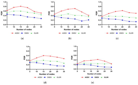
Figure 1.
Packet delivery ratio: (a) SRWP, (b) MP, (c) RDPZ, (d) EGM, and (e) DPR.
In addition, we checked our assumption that the PDR performance of a FANET protocol would increase as the node density increases. As expected, the PDR performance of AODV and OLSR increased to some extent and then began to decrease. For example, in Figure 1a, the PDR performance of AODV increases up to 15 nodes (81%) and then decreases. The PDR performance of OLSR increases up to 15 nodes (60%), and then degrades from 20 nodes. However, in the case of DSDV, the PDR performance did not increase even if the node density increased. DSDV shows the best performance (46%) with five nodes.
| Findings. The FANET routing protocol suitable for our reconnaissance scenario is the reactive routing protocol AODV. In addition, the PDR performance of a FANET protocol does not continue to improve as the density of FANET nodes increases. |
5.2. RQ2: How Does the Connectivity of Nodes in a Network Affect the Performance of a Protocol?
We first use a performance metric called network connectivity ratio (NCR) to find out how node connectivity in a network affects protocol performance. We define and use the NCR metric to understand the connectivity of nodes. The underlying assumption of NCR is that the higher the density of FANET nodes, the better the connectivity of the network.
Figure 2 shows how network connectivity affects routing protocol performance. Given the communication distance of UAV nodes and the topology of the nodes, NCR only indicates the percentage of packets that can be sent from a node to GCS in the network. Therefore, the PDR performance of a routing protocol cannot be higher than the value of NCR. In Figure 2, the center line indicates the maximum performance of PDR. Interestingly, when the NCR value is low, the PDR value is close to the center line. However, when the NCR value becomes higher, the PDR values are farther away from the center line. This means as the NCR value becomes higher, the performance of PDR decreases.
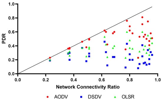
Figure 2.
Packet delivery ratio per network connectivity ratio.
In Figure 2, AODV, a reactive routing protocol, shows a reasonable PDR performance even when the NCR value is close to 1. The PDR performance of AODV is close to the center line. In contrast, the performance of DSDV, a proactive routing protocol, is stuck between 0.2 and 0.4, even if the NCR value becomes higher.
To understand the reasons, we marked the NCR values in Figure 3. For example, in Figure 3a, the gray area represents the NCR values. In the figure, as the number of nodes increases, the NCR value increases. If the number of nodes is 30, the NCR value is close to 1.0. It means that almost all nodes are connected. In this case, we expected that most of the packets could be sent from a node to GCS, and the PDR performance would increase. However, in our simulation, we observed that the PDR performance of AODV, OLSR, and DSDV decreased from when the number of nodes was 20, even if the number of nodes increased.
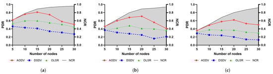
Figure 3.
Packet delivery ratio and network connectivity ratio: (a) SRWP, (b) MP, (c) RDPZ.
| Findings. Even if the connectivity of nodes become higher, the FANET routing protocol performance does not consistently increase. We inferred that it is because the increasing number of nodes causes the overhead of managing a routing table in a protocol. |
5.3. RQ3: Which Mobility Model Shows the Highest PDR Performance in the Reconnaissance Scenario?
We compared the PDR performance of the mobility models to identify the mobility model that shows the best PDR performance with routing protocols. Figure 4 shows the packet delivery ratio of the mobility models for each routing protocol. Figure 4a shows those for AODV, Figure 4b shows those for OLSR, and Figure 4c shows those for DSDV. Through the three figures, the SRWP mobility model shows the highest PDR performance. The MP mobility model comes next, followed by RDPZ and EGM, which yield similar performances. The DPR mobility model shows the lowest performance.
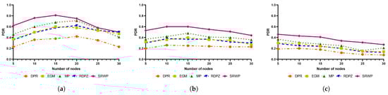
Figure 4.
Packet delivery ratio: (a) AODV, (b) OLSR, and (c) DSDV.
As a reason that mobility models show different PDR performances, we attribute to the proximity of nodes in the UAV-to-GCS communication. In the experiment, we placed the GCS in the center of the area. SRWP, which yields the best performance (81%), randomly selects a destination and then moves in a straight line from the current position to the destination. When moving in this way, it often passes more closely through the center of the operation area compared to other mobility models. It is the reason that SRWP shows the best performance because the nodes in SRWP are close to the GCS, which is located in the center.
Meanwhile, in DPR, which shows the worst performance (42%), the nodes tend to be concentrated in a specific area, but the location is concentrated on the outside rather than the center. Because the nodes are far from the GCS, the PDR performance of DPR could not be high. In the case of RDPZs, nodes move evenly throughout the operational area. As a result, RDPZ has the highest reconnaissance rate among the mobility models for reconnaissance but has a lower PDR than SRWP. Each mobility model may yield different PDR results depending on the location of the GCS, the starting point of the UAVs, and the communication distance.
| Findings. The mobility model suitable for protocol communication is SRWP. Many factors, including the distance between GCS and UAVs, could affect the PDR performance of mobility models. |
5.4. RQ4: How Does the Reconnaissance Rate of a Mobility Model Affect the Performance of the Mobility Model in the Reconnaissance Scenario?
RQ3 only evaluated the PDR performance of routing protocols with different mobility models. The RQ3 result is not enough to identify a suitable mobility model for our reconnaissance scenario, because a mobility model is also expected to evenly reconnoiter the reconnaissance area. For example, there is a mobility model that moves only near the GCS. In this case, the mobility model yields high PDR performance but is not desirable in the reconnaissance scenario. There is another mobility model that moves evenly throughout the reconnaissance area. The mobility model is desirable in the reconnaissance scenario. However, is the mobility model desirable for communication between GCS and nodes? In RQ4, we consider both factors, PDR and a reconnaissance ratio.
When we conducted the experiment, we set up the routing protocol to AODV, because AODV was identified as the best routing protocol through RQ1 and RQ2. Figure 5a–c show the reconnaissance rates of 10 min, 30 min, and 60 min, respectively. The reconnaissance rate becomes higher as time increases. The reconnaissance rate also becomes higher as the number of nodes increases. For instance, Figure 5a shows a 0.4 reconnaissance rate for 10 nodes and shows 0.8 for 30 nodes. Figure 5c shows that when there are 30 nodes, most mobility models cover the operational area. In the experiment, RDPZ shows the highest reconnaissance rate.
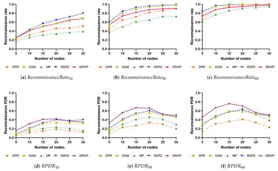
Figure 5.
Reconnaissance packet delivery ratio: (a) reconnaissance rate by the mobility model for 10 min, (b) reconnaissance rate by the mobility model for 30 min, (c) reconnaissance rate by the mobility model for 60 min, (d) RPDR for 10 min, (e) RPDR for 30 min, and (f) RPDR for 60 min.
Figure 5d–f show Reconnaissance PDRs for 10 min, 30 min, and 60 min, respectively. Reconnaissance PDR is the value obtained by multiplying the Reconnaissance Rate by the PDR. In Figure 5d, the SRWP model shows the highest Reconnaissance PDR performance (42%) up to when the number of nodes is 20. After that, the RDPZ model shows the highest Reconnaissance PDR performance (40%). EGM also shows a reasonable Reconnaissance PDR performance (33%). In contrast, DPR and MP show relatively low Reconnaissance PDR performance (19% and 24%, respectively). Figure 5f shows the Reconnaissance PDR performance over 60 min. The highest performance is 76% with SRWP when the number of nodes is 15. The second highest performance is 65% with MP when the number of nodes is 20. The performance of RDPZ is 62% when the number of nodes is 20. The performance of EGM is 59% when the number of nodes is 15. The lowest performance is 41% with DPR when the number of nodes is 20. The average PDR performance is 61% for SRWP, 50% for RDPZ, 49% for EGM, 48% for MP, and 30% for DPR.
We compare the results for RQ4 with the results for RQ3. The results for RQ3 showed good performance in the order of SRWP, MP, RDPZ, EGM, and DPR. The results for RQ4 showed good performance in the order of SRWP, RDPZ, EGM, MP, and DPR. From the comparison, we can see that SRWP reasonably performs in terms of PDR and a reconnaissance ratio. RDPZ model with excellent reconnaissance rate could be suitable for communication between GCS and nodes, as well. In contrast, MP showed high PDR performance. However, when a reconnaissance ratio was considered, MP was not appropriate for our reconnaissance scenario. The reason for this is that we observed that the MP model moves only near the GCS (center of the reconnaissance area) in our simulation.
| Findings. If we consider both the reconnaissance rate of a mobility model and the PDR performance of a mobility model, the mobility models suitable for protocol communication in the reconnaissance scenario is SRWP. Alternatively, RDPZ and EGM can be used for our reconnaissance scenario. |
5.5. RQ5: How Does the GCS Location Affect the Performance of the Mobility Model in the Reconnaissance Scenario?
Figure 6 shows the results of the performance analysis according to the change in the GCS location. In the experiment, we used the AODV routing protocol, which has shown good performance, and we analyzed the performance changes in five mobility models. We set the starting position of the UAV at the bottom. Even if the position of the GCS changes, the starting position of the UAV remains the same. Figure 6a shows the position of the GCS in the simulation area, Figure 6b shows the PDR when the GCS is located at the left top, Figure 6c shows the PDR when the GCS is located at the top, Figure 6d shows the PDR when the GCS is located at the middle, and Figure 6e shows the PDR when the GCR is located at the bottom.
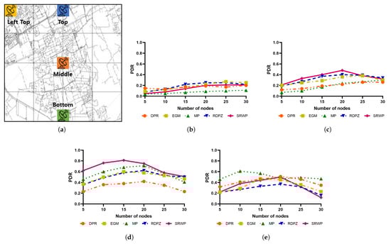
Figure 6.
Performance analysis according to the GCS location: (a) GCS location in the simulation area, (b) left top, (c) top, (d) middle, and (e) bottom.
When the GCS is located in the middle of the reconnaissance area, the mobility models yield high PDR values overall. The PDR values become lower when the GCS is located at the bottom, at the top, and at the left top. Additionally, the five mobility models show different trends across the different GCS locations.
At each different GCS location, a different mobility model shows the highest PDR value. When the GCS is located at the left top, RDPZ shows the highest PRD value. When the GCS is located at the top or in the middle, SWRP shows the highest PRD value. When the GCS is located at the bottom, MP shows a higher PDR value.
The mobility models show different performances according to different GCS locations due to the different mechanisms of the mobility models. For example, in the SRWP model, a UAV moves in a straight line by setting an arbitrary destination from the current location, and this method often passes through the middle. In the MP model, a UAV often hovers at the bottom. The RDPZ model maintains uniform reconnaissance of the operational area, so it is not affected much by the GCS location.
| Findings. the GCS location affects the performance of the mobility model. It is recommended to locate GCS at the center of the reconnaissance area. |
6. Discussion
This section discusses additional experiments that were not addressed in the previous section. Section 6.1 reports the experimental results for the end-to-end delay performance. Section 6.2 reports the experimental results of PDR by changing the speed of nodes. Section 6.3 summarizes all of the experimental results.
6.1. End-to-End Delay
We evaluated the end-to-end delay performance of AODV, DSDV, and OLSR in reconnaissance scenarios. To evaluate the end-to-end delay performance, we measured the end-to-end delay values from 5 nodes to 30 nodes in increments of 5 nodes and averaged the values. Figure 7 is the averaged end-to-end delay of AODV, DSDV, and OLSR. In Figure 7, OLSR yields the lowest end-to-end delay performance, while DSDV yields the highest end-to-end delay performance. AODV yields reasonable end-to-end delay performance. In this end-to-end delay performance, the smallest value represents the best performance, so OLSR has the best performance, followed by AODV and DSDV. Interestingly, DSDV and OLSR are proactive routing protocols, and AODV is a reactive routing protocol. In the reconnaissance scenario, because the topology of nodes frequently changes, many control messages are generated to update the routing table. OLSR selects MPR nodes to manage the routing table, so the control messages do not make much overhead. In contrast, DSDV makes all nodes manage their own routing tables, so the control messages create a great deal of overhead compared to OLSR. AODV updates the routing table only when the updates are needed. As AODV takes time to search the path among nodes, the end-to-end delay performance of AODV is worse than that of OLSR.
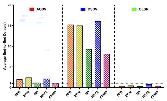
Figure 7.
Average end-to-end delay of routing protocols.
6.2. Speed of Nodes
We also evaluated the PDR performance of AODV, DSDV, and OLSR by changing the speed of nodes. In the experiment, we simulated AODV, DSDV, and OLSR using the SRWP mobility model, which showed the best PDR performance in Section 5.3. When it comes to the number of nodes, we set up 15 nodes which showed the best PDR performance in Section 5.3 overall. Figure 8 shows the experimental results. In our experiment, we find no significant changes in the PDR performance of AODV, DSDV, and OLSR according to the change in the node speed. Our results contradict the findings in the previous studies that reported the speed of nodes influenced the PDR performance changes [8].
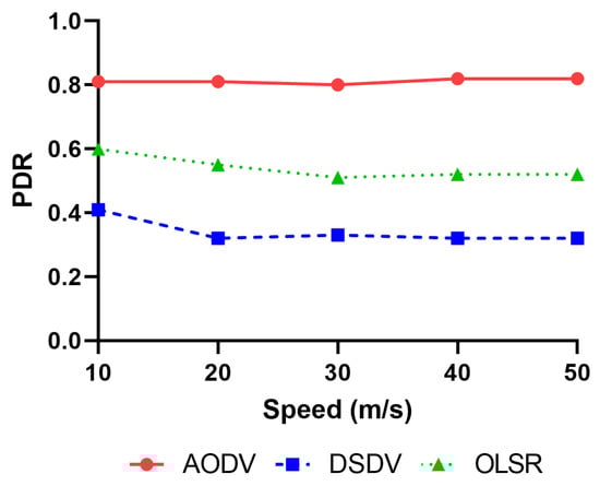
Figure 8.
Packet delivery ratio per speed.
6.3. Summary of Experiments
In this paper, we simulated AODV, DSDV, and OLSR, which are representative routing protocols of FANETs, according to the mobility models when performing multi-UAV-based reconnaissance. As a result, the AODV protocol yielded reasonable PDR performance, while OLSR showed good end-to-end delay performance. Therefore, AODV appears to be suitable for scenarios in which UAV movement is irregular and packet delivery is important, while OLSR is applicable when UAVs need to deliver packets quickly.
We also expected that the more UAVs forming the FANET, the denser the network connectivity; the denser the connectivity, the higher the PDR values. To verify this hypothesis, we conducted a simulation by increasing the number of nodes. However, in our simulation, the PDR decreased as the number of nodes increased. These simulation results help us infer that PDR performance does not improve as the node density increases. Rather, we observed that as the connectivity improves, more route searching overhead and routing table management overhead occur and affect the PDR performance. In FANETs, where topology changes are fast and irregular reconnaissance scenarios are used, the overhead is the largest cause of performance degradation.
In regard to the mobility models, we found that the SRWP model is an adequate model for the reconnaissance scenario because the model shows a high reconnaissance rate and a high packet delivery ratio. However, the SRWP model has an insufficient reconnaissance rate in the outer part of the reconnaissance area. As an alternative model, the RDPZ and EGM models could be used because these models also show a reasonable reconnaissance rate and a reasonable packet delivery ratio. In contrast, the MP model should not be used in the reconnaissance scenario because nodes are flocked to a specific area, so the reconnaissance rate is low. The DPR model should also not be used because of its low packet delivery ratios.
In addition, it was observed that the mobility model with good performance is different according to the GCS location. For example, SRWP shows high performance when the GCS is located in the middle of the reconnaissance area because, in the SRWP model, the node moves in a straight line from the source to the destination and has many chances to be near the GCS. RDPZ shows high performance when the GCS is located at the left top of the reconnaissance area because nodes move around the area evenly. MP shows high performance when the GCS is located at the bottom because nodes move to the bottom because of the mechanism of MP.
6.4. Remaining Issues
There are four remaining issues that we have not experimented with yet. The first issue is an energy-efficient analysis, the second issue is an analysis of the altitudes of UAVs, the third issue is an analysis of different routing protocols, and the last issue is an analysis of the physical characteristics of UAVs.
When it comes to the first issue, a flying ad hoc network (FANET) requires an energy-efficient routing protocol due to the limited battery life of unmanned aerial vehicles (UAVs). In FANETs, UAVs communicate with each other without centralized infrastructure support. Therefore, the energy efficiency of routing protocols is critical to the overall performance and longevity of the network. There are routing protocols that are energy-inefficient and energy-efficient. Energy-inefficient routing protocols may waste energy by selecting paths that are not optimal in terms of energy consumption. It can rapidly deplete battery life, leading to UAV failures and network outages. Energy-efficient routing protocols can choose a route that minimizes energy consumption while maintaining network connectivity. It can extend a UAV’s battery life. Overall, energy-efficient routing protocols are essential to the successful operation of FANETs and can significantly improve the reliability and longevity of networks. To evaluate the performance of FANET routing protocols in terms of energy efficiency, we need to consider several factors, such as the residual energy of a UAV, the distance between nodes, and the quality of the communication link. We leave such an evaluation as future work.
When it comes to the second issue, the choice of altitude for a reconnaissance mission depends on a number of factors such as objectives, threat environment, and capabilities of the reconnaissance UAVs. If a UAV operates at a higher altitude, the UAV’s camera has a wider field of view and can observe a larger area. However, lower image resolution can make it more difficult to identify specific objects. On the other hand, if a UAV operates at a lower altitude, the UAV’s camera may provide a better image resolution. Furthermore, we need to consider the risks of UAVs being detected by air defense systems or enemy forces. We have not experimented with the diversity of altitudes, leaving it as future work.
When it comes to the third issue, there are continuously evolving technologies such as hierarchical swarm scenarios [37] and hybrid routing methods of topology-based routing and geocast routing [28]. As a different direction from the topology-based routing protocols used in this paper, we can set up a new reconnaissance scenario with such technologies. With swarm scenarios, various reconnaissance scenarios could be identified. For example, a reconnaissance scenario in which a fixed wing flies at a high altitude and a rotary wing performs a mission at a lower level could be possible. In this case, we can consider forming a hierarchical network according to the operating altitudes of UAVs. In another case, such as geocast routing, we can consider routing protocols using GPS information maintained by UAVs for various reconnaissance scenarios.
When it comes to the last issue, the physical aspects of a UAV can affect its performance in reconnaissance scenarios. In reconnaissance scenarios, UAVs are used to collect information about a target or area of interest. The UAV’s physical characteristics can affect its ability to perform this effectively. For example, the size, shape, and color of a UAV can affect its ability to covertly collect information without being detected. A UAV’s propulsion system and battery life can affect its ability to stay in the air for a long period of time and cover a large area. A UAV’s payload capacity can also affect the determination of the type and the number of sensors or cameras it can carry to collect information. A UAV’s weight and aerodynamics can affect its stability and maneuverability, which are essential for capturing high-quality images. Therefore, the physical characteristics of a UAV should be designed for specific reconnaissance scenarios to achieve optimal performance and mission success. However, we only consider the communication distance and speed of the UAVs, which is implementable in our network simulator. We leave the considerations on the physical characteristics of the UAVs as future work.
In this paper, we did not include these issues as our experimental conditions. However, we could consider these issues in future research for a reconnaissance scenario closer to a more realistic environment and for adoption of more advanced technologies.
7. Conclusions
In this paper, we analyzed the performance of routing protocols and mobility models that could be used for the multi-UAV-based reconnaissance scenario. In RQ1, we analyzed the PDR performance of AODV, DSDV, and OLSR in the reconnaissance scenario, and we found that AODV, a reactive routing protocol, yielded the highest PDR performance (81%) with SRWP in the reconnaissance scenario. In RQ2, we analyzed routing protocols AODV, DSDV, and OLSR under the consideration of network connectivity in FANET. We found that as the density of nodes increases, the connectivity increases. However, we also found that, even if the connectivity continuously increases, the performance of the routing protocol does not continuously improve. In RQ3, we identified the mobility model with the highest PDR performance in the reconnaissance scenario. We found SWRP as the appropriate mobility model, only if we considered the PDR performance. As a reconnaissance rate was also important for a mobility model, we identified a mobility model adequate for the reconnaissance scenario in consideration of both the PDR performance and the reconnaissance rate in RQ4. As a result, SRWP showed the highest PDR performance of 76%, and RDPZ and EGM models were found to be effective at 62% and 59%. Finally, in RQ5, we analyze the impact of the GCS location on the PDR performance of mobility models in reconnaissance scenarios. We found that as the distribution of nodes was different depending on the mechanism of the mobility model, the GCS location has an impact on the PDR performance of mobility models.
In the future, we would like to evaluate routing protocols and mobility models in more realistic scenarios. For that, as we already discussed in Section 6.4, we could consider the remaining issues, an energy-efficient analysis, an analysis of altitudes of UAVs, an analysis of different routing protocols, and an analysis of the physical characteristics of UAVs. By considering these issues, we will first refine reconnaissance scenarios and classify them. We will then set up a physical environment or develop a simulator that can set up such conditions. Based on the scenarios and environment, we will experiment with and develop a FANET routing protocol that can show excellent performance in reconnaissance scenarios. We will finally evaluate the performance of FANET routing protocols more objectively by scaling up reconnaissance scenarios and experimental environments.
Author Contributions
Conceptualization, T.K. and S.L.; methodology, T.K. and K.H.K.; software, T.K., Y.-I.J. and K.H.K.; validation, T.K., K.H.K. and S.L.; formal analysis, T.K. and K.H.K.; investigation, S.L.; resources, T.K.; writing—original draft preparation, T.K.; writing—review and editing, T.K. and S.L.; visualization, T.K.; supervision, S.L. and K.H.K.; project administration, S.L.; funding acquisition, S.L. All authors have read and agreed to the published version of the manuscript.
Funding
These results were supported by the “Regional Innovation Strategy (RIS)” through the National Research Foundation of Korea (NRF), funded by the Ministry of Education (MOE) (2021RIS-003). This research was also supported by the Program through the National Research Foundation of Korea (NRF) grant, funded by the Ministry of Education (NRF-2021R1A2C1094167).
Institutional Review Board Statement
Not applicable.
Informed Consent Statement
Not applicable.
Data Availability Statement
Not applicable.
Acknowledgments
This research was also supported by Kyungpook National University Research.
Conflicts of Interest
The authors declare no conflict of interest.
Abbreviations
The following abbreviations are used in this manuscript:
| FANET | Flying Ad hoc network |
| MANETs | Mobile Ad hoc networks |
| VANETs | Vehicular Ad hoc networks |
| AODV | Ad hoc On-demand Distance Vector |
| DSDV | Destination Sequenced Distance Vector |
| OLSR | Optimized Link State Routing Protocol |
| SRWP | Smooth Random WayPoint |
| MP | Markov Process |
| RDPZ | Random Destination with Partitioned Zone |
| EGM | Enhanced Gauss–Markov |
| DPR | Distributed Pheromone Repel |
| GCS | Ground control station |
| UAVs | Unmanned aerial vehicles |
| PDR | Packet delivery ratio |
| NCR | Network connectivity ratio |
| RPDR | Reconnaissance packet delivery ratio |
References
- Singh, K.; Verma, A.K. Experimental analysis of AODV, DSDV and OLSR routing protocol for flying adhoc networks (FANETs). In Proceedings of the 2015 IEEE International Conference on Electrical, Computer and Communication Technologies (ICECCT), Coimbatore, India, 5–7 March2015; pp. 1–4. [Google Scholar]
- Li, X.; Yan, J. LEPR: Link stability estimation-based preemptive routing protocol for flying ad hoc networks. In Proceedings of the 2017 IEEE symposium on computers and communications (ISCC), Heraklion, Greece, 3–6 July 2017; pp. 1079–1084. [Google Scholar]
- Garcia-Santiago, A.; Castaneda-Camacho, J.; Guerrero-Castellanos, J.F.; Mino-Aguilar, G. Evaluation of AODV and DSDV routing protocols for a FANET: Further results towards robotic vehicle networks. In Proceedings of the 2018 IEEE 9th Latin American Symposium on Circuits & Systems (LASCAS), Puerto Vallarta, Mexico, 25–28 February 2018; pp. 1–4. [Google Scholar]
- Nayyar, A. Flying adhoc network (FANETs): Simulation based performance comparison of routing protocols: AODV, DSDV, DSR, OLSR, AOMDV and HWMP. In Proceedings of the 2018 International Conference on Advances in Big Data, Computing and Data Communication Systems (icABCD), Durban, South Africa, 6–7 August 2018; pp. 1–9. [Google Scholar]
- Leonov, A.V.; Ryabchevsky, V.O. Performance evaluation of AODV and OLSR routing protocols in relaying networks in organization in mini-UAVs based FANET: Simulation-based study. In Proceedings of the 2018 Dynamics of Systems, Mechanisms and Machines (Dynamics), Omsk, Russia, 13–15 November 2018; pp. 1–6. [Google Scholar]
- Rabahi, F.Z.; Bemmoussat, C.; Benaissa, M. A comparison of different dynamic routing protocols in FANETs. In Proceedings of the 2018 International Conference on Applied Smart Systems (ICASS), Medea, Algeria, 24–25 November 2018; pp. 1–5. [Google Scholar]
- Kumar, S.; Bansal, A.; Raw, R.S. Analysis of effective routing protocols for flying ad hoc networks. Int. J. Smart Veh. Smart Transp. (IJSVST) 2020, 3, 1–18. [Google Scholar] [CrossRef]
- Maistrenko, V.A.; Alexey, L.V.; Danil, V.A. Experimental estimate of using the ant colony optimization algorithm to solve the routing problem in FANET. In Proceedings of the 2016 International Siberian Conference on Control and Communications (SIBCON), Moscow, Russia, 12–14 May 2016; pp. 1–10. [Google Scholar]
- Leonov, A.V. Application of bee colony algorithm for FANET routing. In Proceedings of the 2016 17th International Conference of Young Specialists on Micro/Nanotechnologies and Electron Devices (EDM), Erlagol, Russia, 30 June–4 July 2016; pp. 124–132. [Google Scholar]
- Leonov, A.V.; Litvinov, G.A. Applying AODV and OLSR routing protocols to air-to-air scenario in flying ad hoc networks formed by mini-UAVs. In Proceedings of the 2018 Systems of Signals Generating and Processing in the Field of on Board Communications, Moscow, Russia, 14–15 March 2018; pp. 1–10. [Google Scholar]
- Leonov, A.V.; Litvinov, G.A. Considering AODV and OLSR routing protocols to traffic monitoring scenario in FANET formed by mini-UAVs. In Proceedings of the 2018 XIV International Scientific-Technical Conference on Actual Problems of Electronics Instrument Engineering (APEIE), Novosibirsk, Russia, 2–6 October 2018; pp. 229–237. [Google Scholar]
- Leonov, A.V.; Litvinov, G.A. About applying AODV and OLSR routing protocols to relaying network scenario in FANET with mini-UAVs. In Proceedings of the 2018 XIV International Scientific-Technical Conference on Actual Problems of Electronics Instrument Engineering (APEIE), Novosibirsk, Russia, 2–6 October 2018; pp. 220–228. [Google Scholar]
- Rahman, A.; Mou, J.R. A Comparative Analysis of Routing Protocols using 3D Graph for Flying Ad hoc Networks. In Proceedings of the 2019 4th International Conference on Electrical Information and Communication Technology (EICT), Khulna, Bangladesh, 20–22 December 2019; pp. 1–6. [Google Scholar]
- Ema, R.R.; Anik, A.; Nahar, N.; Rahman, M.A.; Eti, K.P.; Islam, T. Simulation Based Performance Analysis of Proactive, Reactive and Hybrid Routing Protocols in Wireless Sensor Network. In Proceedings of the 2020 11th International Conference on Computing, Communication and Networking Technologies (ICCCNT), Kharagpur, India, 1–3 July 2020; pp. 1–6. [Google Scholar]
- Zhang, W.; Peng, W.; Wang, P. A Heterogeneous Dual-Channel Routing Protocol Based on OLSR for FANETs. In Proceedings of the 2021 2nd International Conference on Electronics, Communications and Information Technology (CECIT), Sanya, China, 27–29 December 2021; pp. 57–64. [Google Scholar]
- Tuli, E.A.; Golam, M.; Kim, D.S.; Lee, J.M. Performance Enhancement of Optimized Link State Routing Protocol by Parameter Configuration for UANET. Drones 2022, 6, 22. [Google Scholar] [CrossRef]
- Guillen-Perez, A.; Montoya, A.M.; Sanchez-Aarnoutse, J.C.; Cano, M.D. A comparative performance evaluation of routing protocols for flying Ad-Hoc networks in real conditions. Appl. Sci. 2021, 11, 4363. [Google Scholar] [CrossRef]
- Singh, K.; Verma, A.K. Applying OLSR routing in FANETs. In Proceedings of the 2014 IEEE International Conference on Advanced Communications, Control and Computing Technologies, Ramanathapuram, India, 8–10 May 2014; pp. 1212–1215. [Google Scholar]
- AlKhatieb, A.; Felemban, E.; Naseer, A. Performance evaluation of ad hoc routing protocols in (FANETs). In Proceedings of the 2020 IEEE Wireless Communications and Networking Conference Workshops (WCNCW), Seoul, Republic of Korea, 6–9 April 2020; pp. 1–6. [Google Scholar]
- Rahmani, A.M.; Ali, S.; Yousefpoor, E.; Yousefpoor, M.S.; Javaheri, D.; Lalbakhsh, P.; Ahmed, O.H.; Hosseinzadeh, M.; Lee, S.W. OLSR+: A new routing method based on fuzzy logic in flying ad hoc networks (FANETs). Veh. Commun. 2022, 36, 100489. [Google Scholar] [CrossRef]
- Sang, Q.; Wu, H.; Xing, L.; Ma, H.; Xie, P. An energy-efficient opportunistic routing protocol based on trajectory prediction for FANETs. IEEE Access 2020, 8, 192009–192020. [Google Scholar] [CrossRef]
- Ahmed, S.B.M.; Hussain, S.A.; Latiff, L.A.; Ahmad, N.; Sam, S.M. Performance Evaluation of FANET Routing Protocols in Disaster Scenarios. In Proceedings of the 2021 IEEE Symposium On Future Telecommunication Technologies (SOFTT), Bandung, Indonesia, 6–7 December 2021; pp. 46–51. [Google Scholar]
- Bahloul, N.E.H.; Boudjit, S.; Abdennebi, M.; Boubiche, D.E. Bio-inspired on demand routing protocol for unmanned aerial vehicles. In Proceedings of the 2017 26th International Conference on Computer Communication and Networks (ICCCN), Vancouver, BC, Canada, 31 July–3 August 2017; pp. 1–6. [Google Scholar]
- Rosati, S.; Krużelecki, K.; Traynard, L.; Mobile, B.R. Speed-aware routing for UAV ad hoc networks. In Proceedings of the 2013 IEEE globecom workshops (GC Wkshps), Atlanta, GA, USA, 9–13 December 2013; pp. 1367–1373. [Google Scholar]
- Zheng, Y.; Wang, Y.; Li, Z.; Dong, L.; Jiang, Y.; Zhang, H. A mobility and load aware OLSR routing protocol for UAV mobile ad hoc networks. In Proceedings of the 2014 International Conference on Information and Communications Technologies (ICT 2014), Nanjing, China, 15–17 May 2014. [Google Scholar]
- Iordanakis, M.; Yannis, D.; Karras, K.; Bogdos, G.; Dilintas, G.; Amirfeiz, M.; Colangelo, G.; Baiotti, S. Ad-hoc routing protocol for aeronautical mobile ad hoc networks. In Proceedings of the Fifth International Symposium on Communication Systems, Networks and Digital Signal Processing (CSNDSP), Patras, Greece, 19–21 July 2006; pp. 1–5. [Google Scholar]
- Le, M.; Park, J.S.; Gerla, M. UAV assisted disruption tolerant routing. In Proceedings of the MILCOM 2006-2006 IEEE Military Communications Conference, Washington, DC, USA, 23–25 October 2006; pp. 1–5. [Google Scholar]
- Oubbati, O.S.; Lakas, A.; Zhou, F.; Güneş, M.; Yagoubi, M.B. A survey on position-based routing protocols for Flying Ad hoc Networks (FANETs). Veh. Commun. 2017, 10, 29–56. [Google Scholar] [CrossRef]
- Oubbati, O.S.; Atiquzzaman, M.; Lorenz, P.; Tareque, M.H.; Hossain, M.S. Routing in flying ad hoc networks: Survey, constraints, and future challenge perspectives. IEEE Access 2019, 7, 81057–81105. [Google Scholar] [CrossRef]
- Lakew, D.S.; Sa’ad, U.; Dao, N.N.; Na, W.; Cho, S. Routing in flying ad hoc networks: A comprehensive survey. IEEE Commun. Surv. Tutor. 2020, 22, 1071–1120. [Google Scholar] [CrossRef]
- Wheeb, A.H.; Nordin, R.; Samah, A.; Alsharif, M.H.; Khan, M.A. Topology-based routing protocols and mobility models for flying ad hoc networks: A contemporary review and future research directions. Drones 2021, 6, 9. [Google Scholar] [CrossRef]
- Broch, J. Dynamic source routing in ad hoc wireless networks. IETF Internet Draft. 1998. Available online: https://www.ietf.org/proceedings/43/I-D/draft-ietf-manet-dsr-00.txt (accessed on 16 February 2023).
- Jo, Y.i.; Lee, S.; Kim, K.H. Overlap Avoidance of Mobility Models for Multi-UAVs Reconnaissance. Appl. Sci. 2020, 10, 4051. [Google Scholar] [CrossRef]
- Kuiper, E.; Nadjm-Tehrani, S. Mobility models for UAV group reconnaissance applications. In Proceedings of the 2006 International Conference on Wireless and Mobile Communications (ICWMC’06), Bucharest, Romania, 29–31 July 2006; p. 33. [Google Scholar]
- Biomo, J.D.M.M.; Kunz, T.; St-Hilaire, M. An enhanced Gauss–Markov mobility model for simulations of unmanned aerial ad hoc networks. In Proceedings of the 2014 7th IFIP Wireless and Mobile Networking Conference (WMNC), Vilamoura, Portugal, 20–22 May 2014; pp. 1–8. [Google Scholar]
- Jo, Y.I.; Fathoni, M.F.; Kim, K. A new mobility model for multi-UAVs reconnaissance based on partitioned zone. Appl. Sci. 2019, 9, 3810. [Google Scholar] [CrossRef]
- Cheriguene, Y.; Bousbaa, F.Z.; Kerrache, C.A.; Djellikh, S.; Lagraa, N.; Lahby, M.; Lakas, A. COCOMA: A resource-optimized cooperative UAVs communication protocol for surveillance and monitoring applications. Wirel. Netw. 2022, 1–17. [Google Scholar] [CrossRef]


Disclaimer/Publisher’s Note: The statements, opinions and data contained in all publications are solely those of the individual author(s) and contributor(s) and not of MDPI and/or the editor(s). MDPI and/or the editor(s) disclaim responsibility for any injury to people or property resulting from any ideas, methods, instructions or products referred to in the content. |
© 2023 by the authors. Licensee MDPI, Basel, Switzerland. This article is an open access article distributed under the terms and conditions of the Creative Commons Attribution (CC BY) license (https://creativecommons.org/licenses/by/4.0/).