Abstract
In this study, we realized a relay network using drones and analyzed the impact of the sway angle of a drone’s attitude on communication in a windy flight environment. Drones in flight act as radio relay stations and communication among them is performed using radio equipment mounted on board. In a windy environment, a directional antenna is used for relay communication among them to avoid interference caused by the spread of radio waves in space and extend the relay distance. However, when wind occurs during flight, the flying attitude of the drone inclines, which causes the beam of the antenna to sway and the communication link to be disconnected, leading to a decrease in the transmission speed. In this study, we statistically evaluated the pitch, yaw, and roll axes of a drone through wind tunnel experiments. Furthermore, the pattern of the swing angle of the drone with respect to the wind speed was investigated using computer simulations to analyze the fluid dynamics and theoretically analyze the swing of the drone. Based on these results, the transmission speed when using a directional antenna was calculated. When the wind speed was 6.0 m/s, the pitch axis deflection angle of the drone was 13 at maximum, and the average transmission speed decreased by 33.3 Mbps. In this study, it was found that in communication between drones due to the wind, the transmission efficiency decreased depending on the sway angle of the aircraft.
1. Introduction
As a part of communication infrastructure, drones are expected to be used for building networks in the air for application in dead zones and during disasters [1,2,3,4]. As illustrated in Figure 1a, drones function as radio repeaters through formation flying in the air. In this case, it is necessary to extend the transmission distance between drones to cover a wide range of the communication area. In addition, in the event of a disaster, the amount of traffic is expected to increase such that high-resolution images of the disaster site and victims captured by cameras mounted on a drone can be transmitted [5]. Further, broadband transmission speed is required. However, in free-space propagation through air, the spread of radio waves is large, and there is a possibility of interference from other relay stations. To address these problems, for example, when using a wireless local area network as a wireless device, wireless stations within the range of radio waves share the wireless band through carrier sense functions and use time division (interference is avoided by performing communication through time division multiple access (TDMA)) [1]. However, when there are several drones in the communication area, there arises the challenge that the communication time allocated by TDMA is significantly reduced.

Figure 1.
Use of relays and directional antennas in drones.
The directional antenna is used as shown in Figure 1b to solve these problems [6,7,8,9,10]. By narrowing the beam widths of radio waves, space utilization efficiency is improved and interference with the surroundings is reduced. Furthermore, by narrowing the beam width, the gain of the antenna increases, and the transmission over a long distance is also improved. As examples of directional antenna implementations, previous studies have investigated lightweight directional antennas using metamaterial reflectors [11] and that for multiple frequency bands with aligned beam widths [12]. However, other problems are caused when directional antennas are used with drones. The drone may tilt its flight attitude owing to the impact of wind during flight. As the beam of the directional antenna swings based on the tilt, the transmission rate drops as the communication link formed by the beam is disconnected.
Because no clear analysis results have been obtained on how a drone shakes owing to wind, it is necessary to analyze the tendency of change in drone attitude based on the wind speed. In this study, we statistically evaluate pitch, yaw, and roll axis sway based on drone flight experiments. Furthermore, by theoretically analyzing the motion of the drone through computer simulation using fluid dynamics, the pattern of the motion angle of the drone corresponding to the wind speed was understood. Based on these results, we calculated the transmission speed when using a directional antenna and confirmed the relationship between the shaking of the drone and the communication speed.
The remainder of the paper is organized as follows. Section 2 summarizes the related works. The communication speed issues with directional antennas are described in Section 3, and the drone tilt based on wind speed is analyzed in Section 4. In Section 5, the communication speed based on shake angle accumulation frequency is evaluated. Finally, conclusions are drawn in Section 6.
2. Related Work
Effects of wind perturbations on drone communications have been studied so far. In this section, we review these related studies by classifying them into design and control of drone networks with wind effects [13,14,15,16,17] and measurement and channel modeling of wind effects [18].
Moorthy and Guan [13] proposed a beam control scheme called LeBeam for mmWave/THz-band wireless networks among drones. In LeBeam, under mobility uncertainties of drones due to the wind perturbations, the optimal beam width is determined by using echo state network (ESN) learning. In [13], ESN is trained with mobility traces collected through field experiments. In [14,15,16,17], wireless networks between drones and ground users or base stations are considered. In [14], drones are used as aerial base stations and cell coverage is analyzed by considering wind perturbations. In [15], cellular-connected drone networks, where drones connect to ground base stations, are considered and a soft-handover scheme is proposed to provide seamless handover between base stations. In [15], the fluctuations of drones are modeled by a random-walk statistical model. In [16], an offline path planning algorithm for cellular-connected drone networks, which determines the flight path of drones in a 2D space, is proposed to maximize the quality of video streaming applications during the flight. The path planning algorithm is formulated by considering the wind effects. In [17], multi-user drone networks, where drones communicate with multiple ground users, are considered, and trajectories of drones are optimized by considering wind effects. The above studies show that wind effects are important for the design and control of drone networks.
Nie et al. [18] study channel modeling in wireless agricultural networks, wireless networks among drones, ground vehicles, and agricultural machinery. To characterize the stability of wireless links with wind effects, the average and minimum signal-to-noise ratios (SNRs) are evaluated under different wind speed statistics collected through field experiments. Although reference [18] provides important experimental results on wind effects, this study has two different contributions. One is that the wind statistics are collected through the wind tunnel. By using the wind tunnel, the behaviors of the drone can be measured in detail because the wind speed can be adjusted and the motion of the drone can be properly captured with cameras placed inside the wind tunnel. The other is that the wind effects are analyzed in drone networks with directional antennas. Because wireless links among drones can be regarded as free-space propagation channels, directional antennas are important to alleviate interference. However, the communication qualities of wireless links are sensitive to the wind effects, especially in drone networks with narrow beam width antennas. Therefore, the analyses of the wind effects in this study provide important insights into the design of future drone networks.
3. Communication Speed Issues with Directional Antennas
When a directional antenna is mounted on a drone, a high transmission rate can be maintained, even between distant drones. If the beam width (half-value angle) of the antenna is reduced, the gain of the antenna increases:
The signal power on the receiver side is obtained by subtracting the free-space propagation loss L from the antenna gain and the antenna gain on the receiver side, with the power on the transmitter side of the drone . We refer to Table 1 for the received signal power and the Modulation and Coding Scheme (MCS) index and determine the transmission rate based on IEEE802.11a [9,19]. In addition, in Formula (1), is the beam width (half-value angle) of the directional antenna, (= 0 is the radiation angle at the front of the antenna, and L indicates the propagation loss in free space and is expressed by Formula (2). Furthermore, f is the frequency used, D is the distance between the transmitting and receiving drones, c is the speed of light, and the loss L attenuates logarithmically depending on the distance and frequency. In addition, the radiation pattern of the antenna is obtained using Formula (3) [9], and the antenna gain of the transmitter and receiver in Formula (1) is also obtained using Formula (3) [9,19,20]. The antenna gain is approximated using Formula (3) [20], and in Formula (3) refers to the radiation angle in the radiation pattern. Thus, the antenna gain for each antenna beam width can be derived. The radiation pattern in Figure 2 indicates that the beam width changes from 15 up to 90.

Table 1.
IEEE 802.11 standard transmission rate and reception sensitivity.
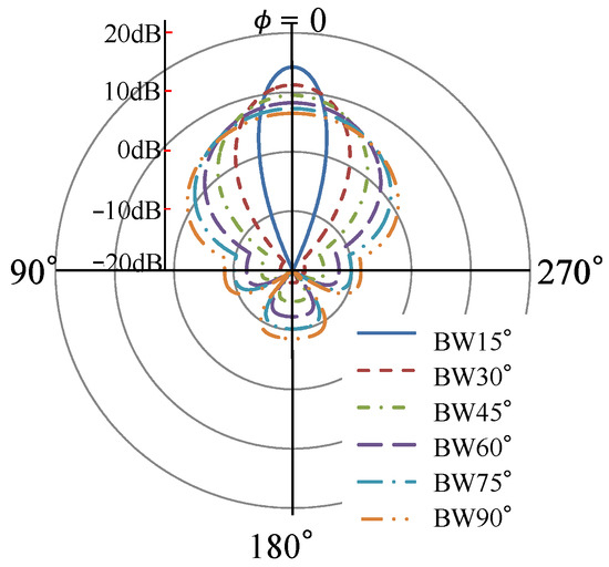
Figure 2.
Directional beam radiation pattern.
Figure 3 depicts the transmission rate versus the beam width of the radiation pattern obtained from these equations. As indicated in the figure, a narrower beam width results in a longer transmission distance between the drones and a higher transmission speed. However, when the beam width is narrow and the drone attitude is tilted by the wind, the beam axis between the drones is altered, as illustrated in Figure 4, and the transmission speed decreases. Formula (3) is used to calculate the transmission speed when the two relay drones are tilted simultaneously at the same angle, as depicted in Figure 4:
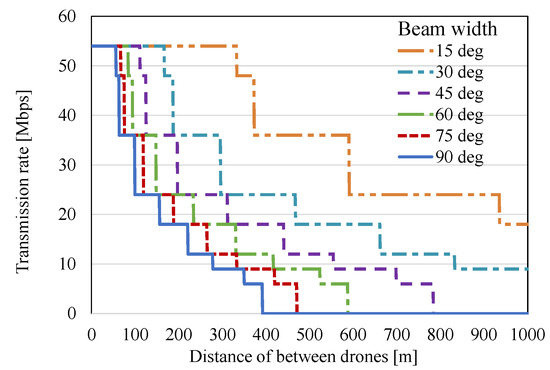
Figure 3.
Transmission speed versus transmission distance when the beam width is different.
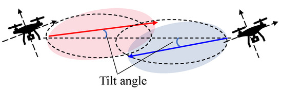
Figure 4.
Beam axis based on drone tilt.
Using Equation (5), the antenna gain at the tilt angle at the drone transmitter/receiver is used to calculate the signal power. Using the MCS index recommended by the IEEE802.11 standard and the received power at the minimum reception sensitivity recommended by the IEEE802.11a standard (Table 1), the transmission speed when the drone is tilted is calculated.
Figure 5 depicts the transmission speed versus the drone tilt when the beam width obtained from these equations was changed. The drone assumed a tilt of the pitch axis and was set in the range of 0–60. The narrower the beam width, the lower the transmission rate with respect to the drone tilt. At a beam width of 15, which achieved the highest transmission rate according to Figure 3, the link between the drones was cut off at a tilt of approximately 15. The drone tilt owing to the wind is a significant factor when using a directional antenna, and it is necessary to analyze the tendency of the drone tilt with respect to the wind speed.
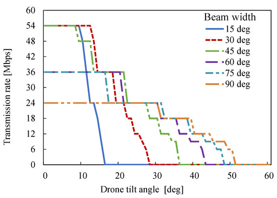
Figure 5.
Relationship between beam width and drone tilt.
4. Analysis of Drone Tilt Based on Wind Speed
4.1. Evaluation of Inclination through Wind Tunnel Experiment
A wind tunnel experiment was conducted to verify the tilt and shake patterns of the drone with respect to the wind speed. The experimental setup is illustrated in Figure 6. Through flight control, the drone was hovering and stationary at the same position, and the circulator generated wind from one direction. A reflective marker was installed on the drone, and motion capture using an infrared camera was used to analyze the drone tilt. These measurements were performed using the software Motive [21]. The wind speed of the circulator was changed from 0.0 to 6.0 m/s, which is above the flight limit wind speed of the drone, referring to the flight manual [22,23] published by the Ministry of Land, Infrastructure, Transport, and Tourism. In the experiment, we used the commercially available Mavic Air drone, which exhibits relatively stable hovering behavior [24]. Because the drone is equipped with a GPS and vision positioning sensor, it is equipped with a function that automatically controls the drone’s position and attitude itself. The measurement time through motion capture was set to 1 min, and data were collected at 0.1-s intervals.
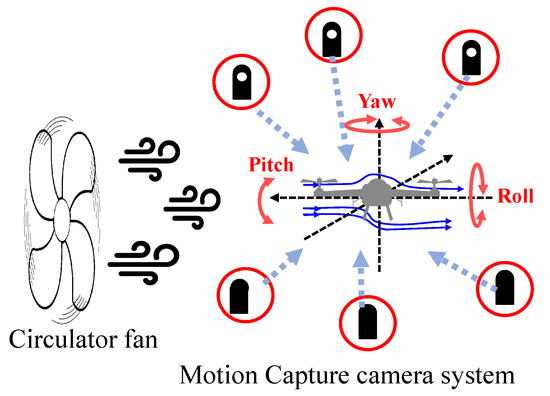
Figure 6.
Configuration of the wind tunnel experiment.
Figure 7 shows the experimental scene, in which the wind was generated by a circulator with adjustable wind speed. Surrounding multiple cameras show motion capture. This wind experiment conditions were the simple test method, such as the experiment scene shown in Figure 7. Since the actual flight environment is different between this experiment and the sky, atmospheric pressure may also have effects. However, the key aim of these experiments is to analyze the behavior of the drone against wind pressure. Moreover, similar results are obtained even if the shape of the drone is slightly different. Thus, in this experiment, we will investigate the tilt tendency that occurs even if the flight environment is different, and explore the possibility of influencing the transmission rate.
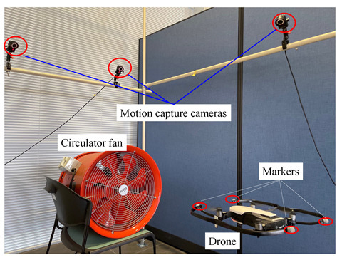
Figure 7.
Experiment scenery.
Figure 8a–c depicts the swing angles of the pitch, yaw, and roll axes, respectively, for each wind speed obtained in the experiment. The horizontal axis indicates the shake angle of each axis and the vertical axis indicates the normalized value of the occurrence frequency of the shake angle. The yaw axis in Figure 8b does not indicate a large deflection even when the wind speed is increased. However, the swing angles of the pitch and roll axes increase as the wind speed increases. The pitch axis has a maximum deflection angle of 20 at a wind speed of 6.0 m/s and is considered to have a significant effect on the direction of the directional beam. In addition, the roll axis has a high deflection frequency in the range of 10–13. However, in the case of a balloon-shaped radiation pattern, since the roll axis tilt rotates around the antenna, the beam direction does not have an influence significantly. However, if the polarization wave planes do not match, the antenna gain will decrease. As a result of the analysis, the reduced antenna gain was not occurred due to the plane of polarization wave. Details are explained in Appendix A. From these experimental results, it was confirmed that the swing angle of the pitch axis was dominant owing to the wind.
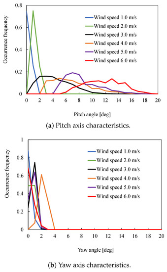
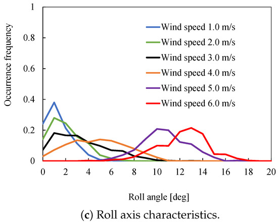
Figure 8.
Shaking characteristics against wind speed.
4.2. Hydrodynamic Verification
The results of the wind tunnel experiment confirmed that the swing of the pitch axis is dominant. However, in this study, we further analyzed the principle of the swing of the drone on the pitch axis hydrodynamically. For the hydrodynamic computer simulation, a simple-shaped drone was drawn and evaluated, as depicted in Figure 9. The figure presents the evaluation results for the air pressure distribution generated at a wind speed of 6.0 m/s, which had the most significant effect. In the experiment, it was confirmed that the impact of the pitch axis is large; therefore, the simulator (flowsquare+) [25] evaluated the fluid and its pressure distribution on a two-dimensional plane. Figure 9a depicts the air pressure distribution when a fluid (wind) is generated on the drone, which varies significantly over a period of approximately 0.2 s. It is assumed that the drone tilts either up or down because of the high pressure applied to the tip of the airframe. Figure 9b depicts a periodic variation in the atmospheric pressure distribution; the drone may swing along the pitch axis owing to the Karman vortices generated behind the drone and variations in the pressure above and below the fuselage. Figure 10a,b depicts the results of the analysis of the lift and drag forces, respectively, used to analyze the specific swing angle. The horizontal axis in each graph represents the lift and drag forces (at intervals of 0.01 N), and the vertical axis represents the normalized value of the force occurrence frequency (N). Maximum drag and lift forces of 6.3 and 4 N (at a wind speed of 6.0 m/s), respectively, were generated, and it was confirmed that both sets of data tend to be discrete. In addition, as a tendency of the data, the maximum and minimum values of the discrete data at each wind speed occur frequently. Therefore, it can be seen that the force applied to the airframe repeats the maximum and minimum values at regular intervals. Based on the obtained drag and lift data, we studied the drone swing angle using the theory depicted in Figure 11. As illustrated in the figure, when the fluid (wind) flows into the airframe, the drag force acts in a direction parallel to the fluid. A drone can hover by changing its attitude angle against this drag force, with the force lift acting in the direction perpendicular to gravity [26]. That is, the swing angle of the drone is generated because these two forces balance each other. The deflection angle for the drone is obtained using the following equation:
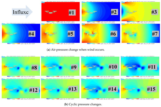
Figure 9.
Results of the evaluation of the fluid and pressure distribution.
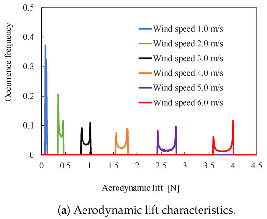
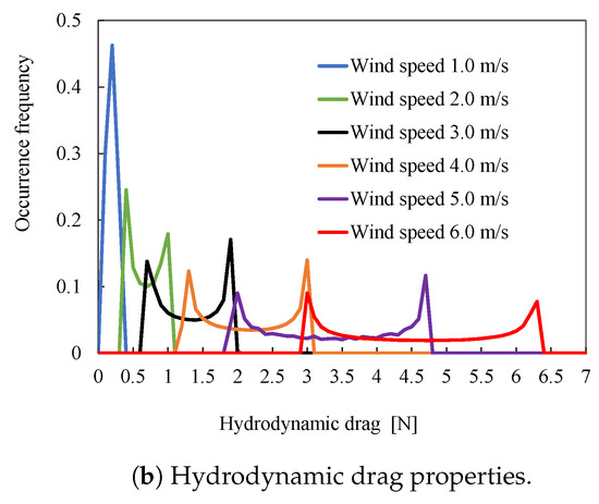
Figure 10.
Simulated force properties.
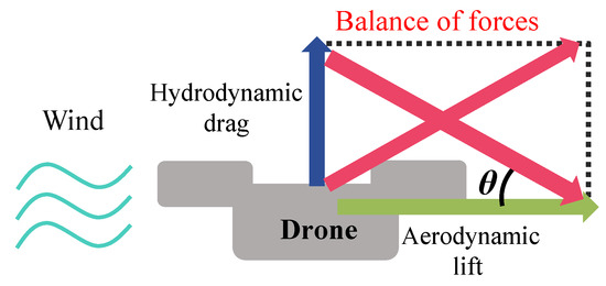
Figure 11.
Relationship between lift and drag.
As shown in Formula (6), the force acting in the vertical direction, lift A, gravity g, weight of the aircraft W, force acting in the horizontal direction, and drag force [27,28] can be used to obtain the theoretical drone swing angle from H. Figure 12 depicts the sway angle obtained theoretically from the two datasets of lift and drag obtained from the simulation. The maximum deflection angle was 20 at a wind speed of 6.0 m/s, and it was confirmed that there was a range of deflection angles for each wind speed. The simulation results are compared with the experimental values plotted on the pitch axis in Figure 8a. The distribution of the swing angle for each pitch angle at each wind speed is the same, and it can be confirmed that the tendency of the pitch axis swing and the characteristics according to the wind speed are almost the same. However, there is a difference in the statistical value of the cumulative frequency of the swing angle. In addition, the overall discrete tendency for the experimental values is large. The following reason is considered for this: the drone used in the experiment generates a drag force to offset its shaking owing to the attitude control incorporated in the flight controller [29,30]. From the experimental results as well as those of the fluid analysis, it was verified that the swing angle of the drone owing to the wind and its tendency were in general agreement theoretically.
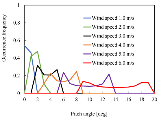
Figure 12.
Theoretical tilt caused by fluid dynamics.
5. Evaluation of Communication Speed Based on Shake Angle Accumulation Frequency
The transmission rate is calculated using the statistical value of the accumulated frequency at the shake angle obtained experimentally. The transmission speed is calculated based on the deflection angle using Formulas (2)–(5). Figure 13 depicts the ratio of each transmission rate (probability of establishing a link) based on the shaking and wind speed. The rate of transmission was calculated as follows:
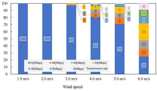
Figure 13.
Ratio of transmission rate to wind speed.
For each wind speed, the ratio P represented by the number of data U for each transmission speed to the total number A of data n for all transmission speeds is calculated as follows:
Assuming the probability X for all possible transmission rates to be 1, the transmission probabilities x for each transmission rate are accumulated. This enables us to determine how low the drone sways per unit time.
As for the change in the ratio of the transmission rate for each wind speed, the transmission speed begins to decrease from a wind speed of 3.0 m/s, and as the wind speed increases, the ratio at which communication can be performed at a high transmission speed decreases. As shown in Figure 14, the average transmission rate also decreases rapidly at the wind speed of 5.0 m/s; it drops to approximately 33 Mbps at the wind speed of 6.0 m/s. That is, the effect of wind fluctuations on communication can be attributed to the fact that the swing of the pitch axis leads to a decrease in the antenna gain. An antenna with a wide beam width is required on the pitch axis plane.
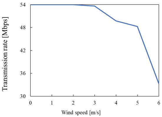
Figure 14.
Average transmission rate.
Transmission rate evaluation so far only considered the impact of beam misalignment. Rigorously practical environment will contain impacts of the small-scale fading and the Doppler shift by the drone’s movement due to the wind. With the former, air-to-air communication environment that we assume is line-of-sight (LoS) dominant channel. Further, beamforming originally attempts to obtain the dominant path and reflection paths are well-suppressed. Therefore, we can certainly expect almost stable frequency-flat channel without small-scale fading. As for the latter issue, the drone rotation due to the wind, especially in the pitch and the yaw axes, could cause the Doppler shift. The Doppler shift, , can be represented as [31]
where v, , and denote the moving speed of the drone, wavelength, and direction of arrival (DoA) of the incident wave, respectively. When the beam is mechanically directed to DoA, the drone’s rotation due to wind is approximately perpendicular to DoA. In other words, the DoA of the radio wave relative to the direction of movement, , is almost 90, so the effective Doppler shift is close to zero and its impact can be negligibly small.
6. Conclusions
In this study, we investigated how the sway angle of the drone’s attitude affects its communication performance in a windy flight environment. In the presence of wind during flight, the flying attitude of the drone tilts; therefore, the beam of the directional antenna swings, and the communication link in the repeater section is disconnected, leading to a decrease in the transmission speed. In this study, we statistically evaluated the pitch, yaw, and roll angles of a drone using wind tunnel experiments. Furthermore, by theoretically analyzing the motion of the drone using a computer simulation of fluid dynamics, we investigated the pattern of the motion angle of the drone based on the wind speed. Based on these results, we calculated the transmission speed when using a directional antenna. When the wind speed was 6.0 m/s, it was confirmed that the maximum deflection angle of the drone was 13, and the transmission speed decreased by 33.3 Mbps. In addition, because the deflection of the pitch axis caused a decrease in the antenna gain, an antenna with a wide beam width was required on the pitch axis plane.
Author Contributions
Conceptualization, T.H. and T.M.; methodology, T.H., T.I. and J.H.; validation, Y.T., T.H. and H.S.; investigation, Y.T. and T.K.; resources, Y.T.; data curation, Y.T.; writing—original draft preparation, Y.T. and T.H.; writing—review and editing, T.H. and T.K.; visualization, Y.T.; supervision, T.M., T.I., J.H. and K.M.; project administration, H.S. and K.M.; funding acquisition, T.H. All authors have read and agreed to the published version of the manuscript.
Funding
Part of the results of this research was supported by the Ministry of Internal Affairs and Communications SCOPE (receipt number JP215004001). Part of the results of this research were supported by the Institute of Biological Sciences Support Center “Innovation Creation Enhancement Research Promotion Project” (JPJ007097) and “Strategic Smart Agricultural Technology Development and Improvement Project” (JPJ011397).
Data Availability Statement
Data are available from the authors upon request.
Conflicts of Interest
The authors declare no conflict of interest.
Appendix A. Effects of Roll Axis Tilt
The roll axis tilt on the drone rotates around the antenna; the gain does not decrease due to the deviation of the beam direction because the antenna pattern is the balloon shape. However, the antenna must use the same polarization, either vertical or horizontal polarization wave, at both the transmitter and receiver. If this polarization plane shifts between the transmitter and the receiver, the antenna gain will decrease. Therefore, the roll axis tilt may cause a mismatch in the polarization plane between the transmitter and receiver. The following equation shows the effect of the roll axis tilt on the antenna gain.
where is the antenna gain including the tilt of the polarization plane, G is antenna gain, is the angle at which the roll axis of the transmitter and receiver fluctuates. The calculated is shown in Figure A1. This result is the sum of antenna gains in the transmitter and receiver. The transmission rate was calculated using this antenna gain calculated. Figure A2 shows the transmission rate when the roll axis on the drone changes up to 90. On the other hand, referring to the roll axis characteristics in Figure 8c, the maximum roll angle is about 18. However, the roll angle that the transmission rate is reduced to is 30 or more in Figure A2. Moreover, disconnected, it is impossible for the angle to be 70 or more. In these results, the roll axis tilt will not affect communication significantly. In the first place, if the drone tilts this much, the flight itself is very difficult. Therefore, in this study, we focused only on the pitch axis.

Figure A1.
The sum of antenna gains ( ) in the transmitter and receiver.
Figure A1.
The sum of antenna gains ( ) in the transmitter and receiver.


Figure A2.
Relationship between roll axis and transmission rate.
Figure A2.
Relationship between roll axis and transmission rate.

References
- Shiraki, N.; Hiraguri, T.; Shitara, I.; Honma, N. Theoretical analysis of interference between directional beams in drone-based 3D mesh network. IEICE Commun. Express 2020, 9, 72–76. [Google Scholar] [CrossRef]
- Hiraguri, T.; Nishimori, K.; Shitara, I.; Mitsui, T.; Shindo, T.; Kimura, T.; Matsuda, T.; Yoshino, H. A cooperative transmission scheme in drone-based networks. IEEE Trans. Veh. Technol. 2020, 69, 2905–2914. [Google Scholar] [CrossRef]
- Matsuda, T.; Kaneko, M.; Hiraguri, T.; Nishimori, K.; Kimura, T.; Nakao, A. Adaptive direction control for UAV full-duplex relay networks using multiple directional antennas. IEEE Access 2020, 8, 85083–85093. [Google Scholar] [CrossRef]
- Nakayama, Y.; Hisano, D.; Maruta, K. Adaptive C-RAN Architecture with Moving Nodes Toward Beyond the 5G Era. IEEE Netw. 2020, 34, 249–255. [Google Scholar] [CrossRef]
- Yu, T.; Takaku, Y.; Kaieda, Y.; Sakaguchi, K. Design and PoC Implementation of Mmwave-Based Offloading-Enabled UAV Surveillance System. IEEE Open J. Veh. Technol. 2021, 2, 436–447. [Google Scholar] [CrossRef]
- IEEE Std. 802.11; Part 11: Wireless LAN Medium Access Control (MAC) and Physical Layer (PHY) Specifications. IEEE Standards Association: Piscataway, NJ, USA, 2012.
- Morino, Y.; Hiraguri, T.; Yoshino, H.; Nishimori, K.; Matsuda, T. A novel collision avoidance scheme using optimized contention window in dense wireless LAN environments. IEICE Trans. Commun. 2016, 99, 2426–2434. [Google Scholar] [CrossRef]
- Hiraguri, T.; Nishimori, K. Survey of transmission methods and efficiency using MIMO technologies for wireless LAN systems. IEICE Trans. Commun. 2015, 98, 1250–1267. [Google Scholar] [CrossRef]
- Nishimori, K.; Yomo, H.; Popovski, P. Distributed interference cancellation for cognitive radios using periodic signals of the primary system. IEEE Trans. Wirel. Commun. 2011, 10, 2971–2981. [Google Scholar] [CrossRef]
- Pandi, S.; Gabriel, F.; Zhdanenko, O.; Wunderlich, S.; HP Fitzek, F. MESHMERIZE: An interactive demo of resilient mesh networks in drones. In Proceedings of the 2019 16th IEEE Annual Consumer Communications & Networking Conference (CCNC), Las Vegas, NV, USA, 11–14 January 2019; IEEE: Piscataway, NJ, USA, 2019; pp. 1–2. [Google Scholar]
- So, H.; Maruta, K. Directional Antenna With Lightweight Metamaterial Reflector for UAV-Based Networks. IEEE Access 2021, 9, 78735–78741. [Google Scholar] [CrossRef]
- So, H.; Maruta, K. Sector Design Using Multiband Antenna With Metamaterial Reflector for Cellular UAV System. IEEE Access 2022, 10, 4924–4933. [Google Scholar] [CrossRef]
- Moorthy, S.K.; Guan, Z. Beam Learning in MmWave/THz-Band Drone Networks Under In-Flight Mobility Uncertainties. IEEE Trans. Mob. Comput. 2022, 21, 1945–1957. [Google Scholar] [CrossRef]
- Sharma, N.; Sharma, V.; Magarini, M.; Pervaiz, H.; Alam, M.M.; Moullec, Y.L. Cell Coverage Analysis of a Low Altitude Aerial Base Station in Wind Perturbations. In Proceedings of the 2019 IEEE Globecom Workshops (GC Wkshps), Waikoloa, HI, USA, 9–13 December 2019; IEEE: Piscataway, NJ, USA, 2019; pp. 1–6. [Google Scholar] [CrossRef]
- Liu, Z.; Zhou, E.; Cui, J.; Dong, Z.; Fan, P. A Double-Beam Soft Handover Scheme and Its Performance Analysis for Mmwave UAV Communications in Windy Scenarios. IEEE Trans. Veh. Technol. 2022. [Google Scholar] [CrossRef]
- Mardani, A.; Chiaberge, M.; Giaccone, P. Communication-Aware UAV Path Planning. IEEE Access 2019, 7, 52609–52621. [Google Scholar] [CrossRef]
- Xu, D.; Sun, Y.; Ng, D.W.K.; Schober, R. Multiuser MISO UAV Communications in Uncertain Environments with No-Fly Zones: Robust Trajectory and Resource Allocation Design. IEEE Trans. Commun. 2020, 68, 3153–3172. [Google Scholar] [CrossRef]
- Nie, S.; Lunar, M.M.; Bai, G.; Ge, Y.; Pitla, S.; Koksal, C.E.; Vuran, M.C. mmWave on a Farm: Channel Modeling for Wireless Agricultural Networks at Broadband Millimeter-Wave Frequency. In Proceedings of the 2022 19th Annual IEEE International Conference on Sensing, Communication, and Networking (SECON), Stockholm, Sweden, 20–23 September 2022; pp. 388–396. [Google Scholar] [CrossRef]
- IEEE 802.11. 2008. Available online: http://www.ieee802.org/11/ (accessed on 2 February 2023).
- Kraus, J.D. Antennas, 2nd ed.; McGraw-Hill: New York, NY, USA, 1998. [Google Scholar]
- Motive2.0.2. 2018. Available online: https://www.optitrack.jp/products/software/ (accessed on 2 February 2023).
- Ministry of Land, Infrastructure, Transport and Tourism. Learn more about the registration system and remote ID! In Handbook for Unmanned Aircraft Registration; Ministry of Land, Infrastructure, Transport and Tourism: Tokyo, Japan, 2022. [Google Scholar]
- Ministry of Land, Infrastructure, Transport and Tourism. Unmanned Aerial Vehicle Manual (DID/Night/Out of Visual Line of Sight/30m/Hazardous Material/Object Drop). In Ministry of Land, Infrastructure, Transport and Tourism Civil Aviation Bureau Standard Manual; Ministry of Land, Infrastructure, Transport and Tourism: Tokyo, Japan, 2020. [Google Scholar]
- Mavic Air2. 2022. Available online: https://www.dji.com/jp/mavic-air-2/specs (accessed on 2 February 2023).
- Flowsquare+. 2021. Available online: http://flowsquare.com/ (accessed on 2 February 2023).
- Janszen, J.; Shahzaad, B.; Alkouz, B.; Bouguettaya, A. Constraint-aware trajectory for drone delivery services. In Proceedings of the Service-Oriented Computing–ICSOC 2021 Workshops: AIOps, STRAPS, AI-PA and Satellite Events, Dubai, United Arab Emirates, 22–25 November 2021; Springer: Berlin/Heidelberg, Germany, 2022; pp. 306–310. [Google Scholar]
- Drela, M. Power balance in aerodynamic flows. AIAA J. 2009, 47, 1761–1771. [Google Scholar] [CrossRef]
- Cambridge University Aeronautics Laboratory. Measurement of Profile Drag by the Pitot-Traverse Method; HM Stationery Office: Richmond, UK, 1936. [Google Scholar]
- Schiano, F.; Alonso-Mora, J.; Rudin, K.; Beardsley, P.; Siegwart, R.; Sicilianok, B. Towards estimation and correction of wind effects on a quadrotor UAV. In Proceedings of the International Micro Air Vehicle Conference and Competition 2014 (IMAV 2014), Delft, The Netherlands, 12–15 August 2014; pp. 134–141. [Google Scholar]
- Pflimlin, J.M.; Soueres, P.; Hamel, T. Hovering flight stabilization in wind gusts for ducted fan UAV. In Proceedings of the 43rd IEEE Conference on Decision and Control (CDC), Nassau, Bahamas, 14–17 December 2004; IEEE: Piscataway, NJ, USA, 2004; Volume 4, pp. 3491–3496. [Google Scholar]
- Jakes, W.C. Microwave Mobile Communications; IEEE Press: Piscataway, NJ, USA, 1974. [Google Scholar]


Disclaimer/Publisher’s Note: The statements, opinions and data contained in all publications are solely those of the individual author(s) and contributor(s) and not of MDPI and/or the editor(s). MDPI and/or the editor(s) disclaim responsibility for any injury to people or property resulting from any ideas, methods, instructions or products referred to in the content. |
© 2023 by the authors. Licensee MDPI, Basel, Switzerland. This article is an open access article distributed under the terms and conditions of the Creative Commons Attribution (CC BY) license (https://creativecommons.org/licenses/by/4.0/).