Cable-Driven Unmanned Aerial Manipulator Systems for Water Sampling: Design, Modeling, and Control
Abstract
1. Introduction
- (i)
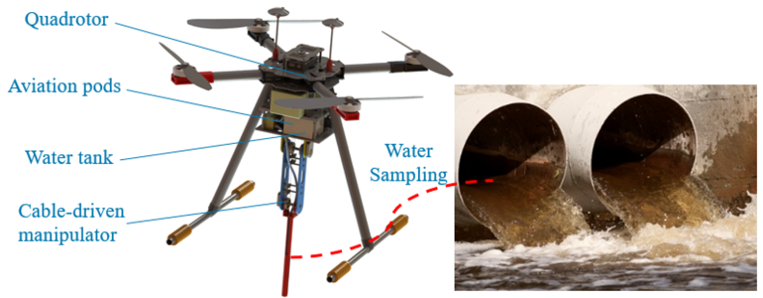
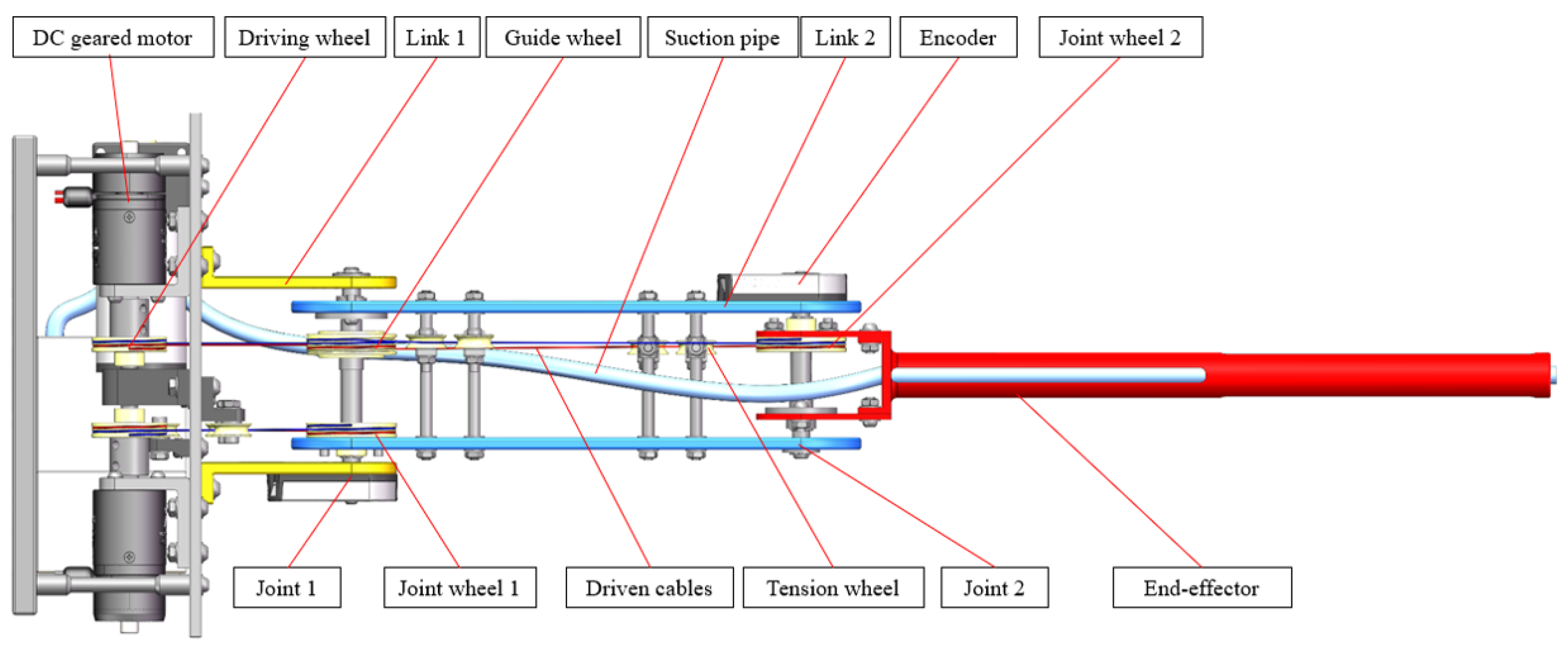
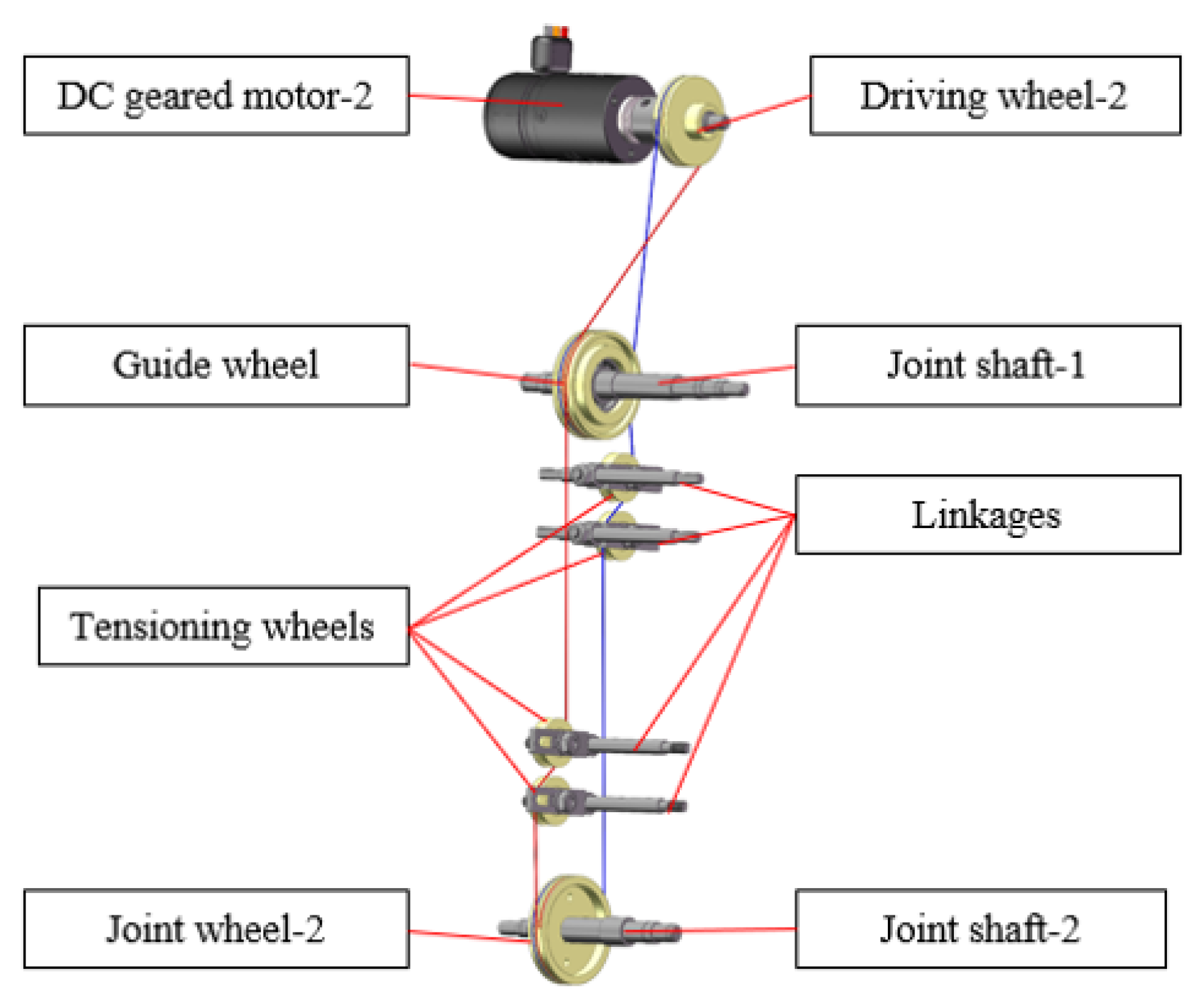
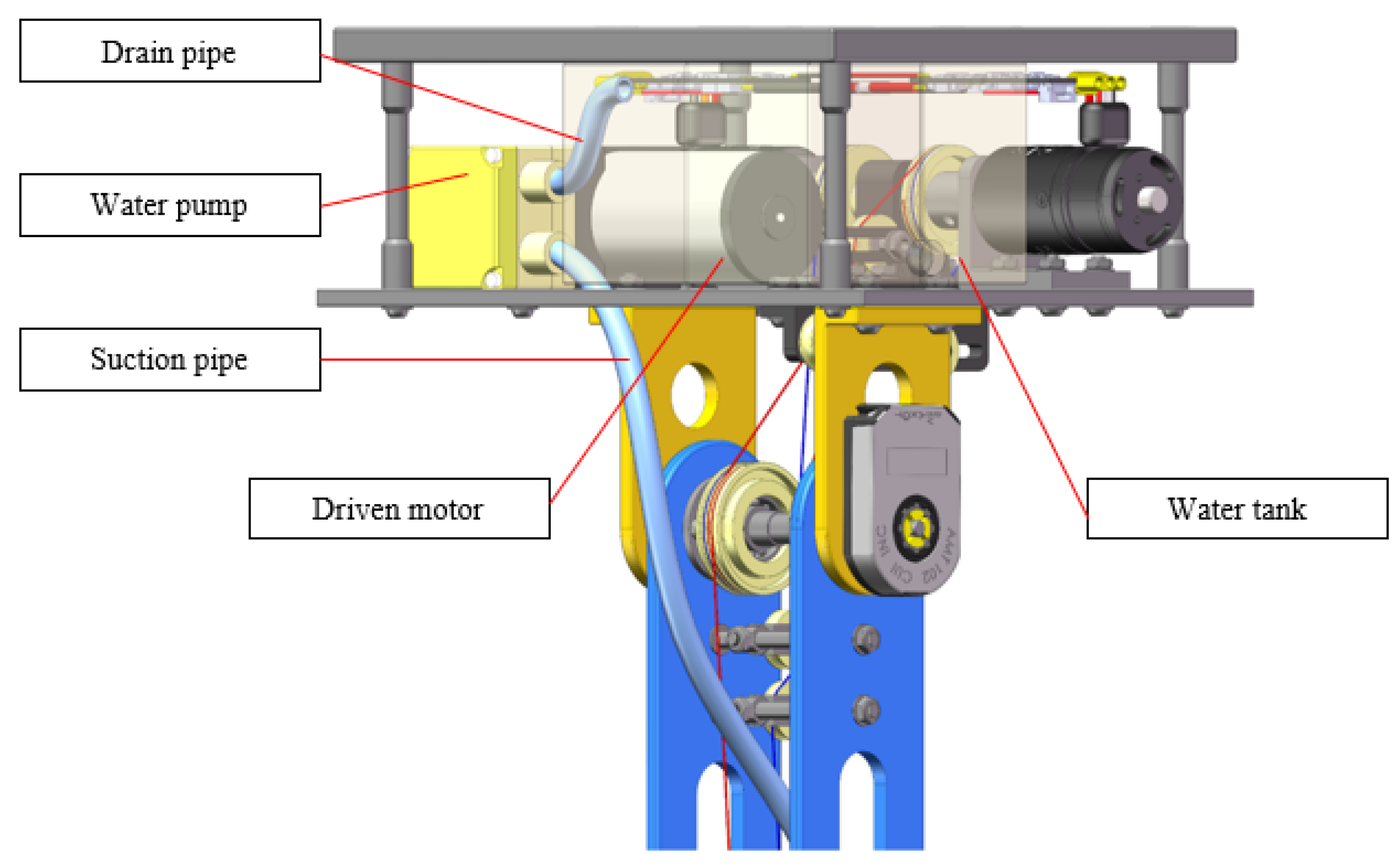
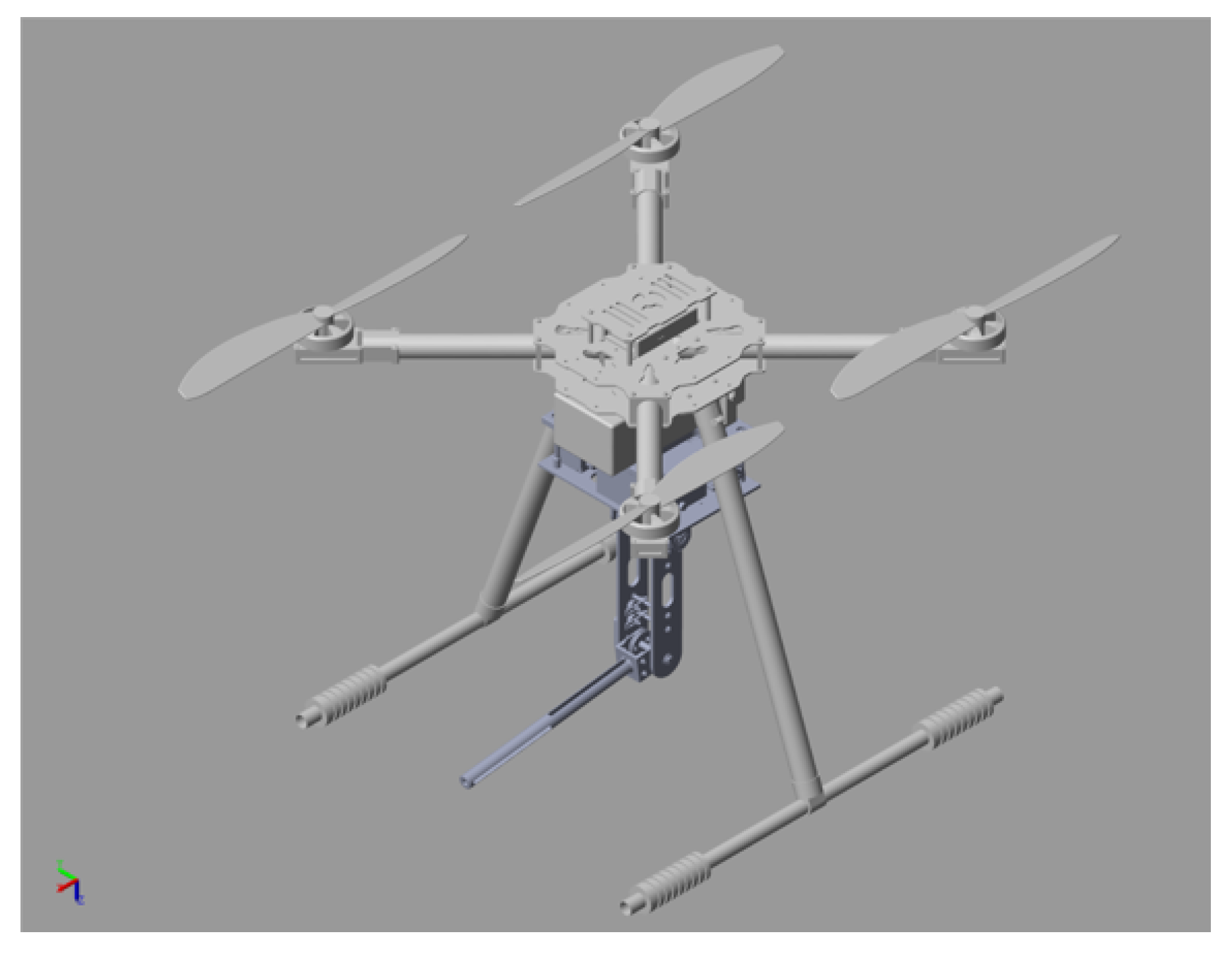
- We designed a flying robot equipped with a cable-driven aerial manipulator to collect water samples at the drain outlets. This design can effectively reduce the weight of the robotic arm and joint inertia, and improve the duty ratio of the end effector. As a result, our robotic arms are lightweight, dexterous, and capable of a fast response.
- (ii)
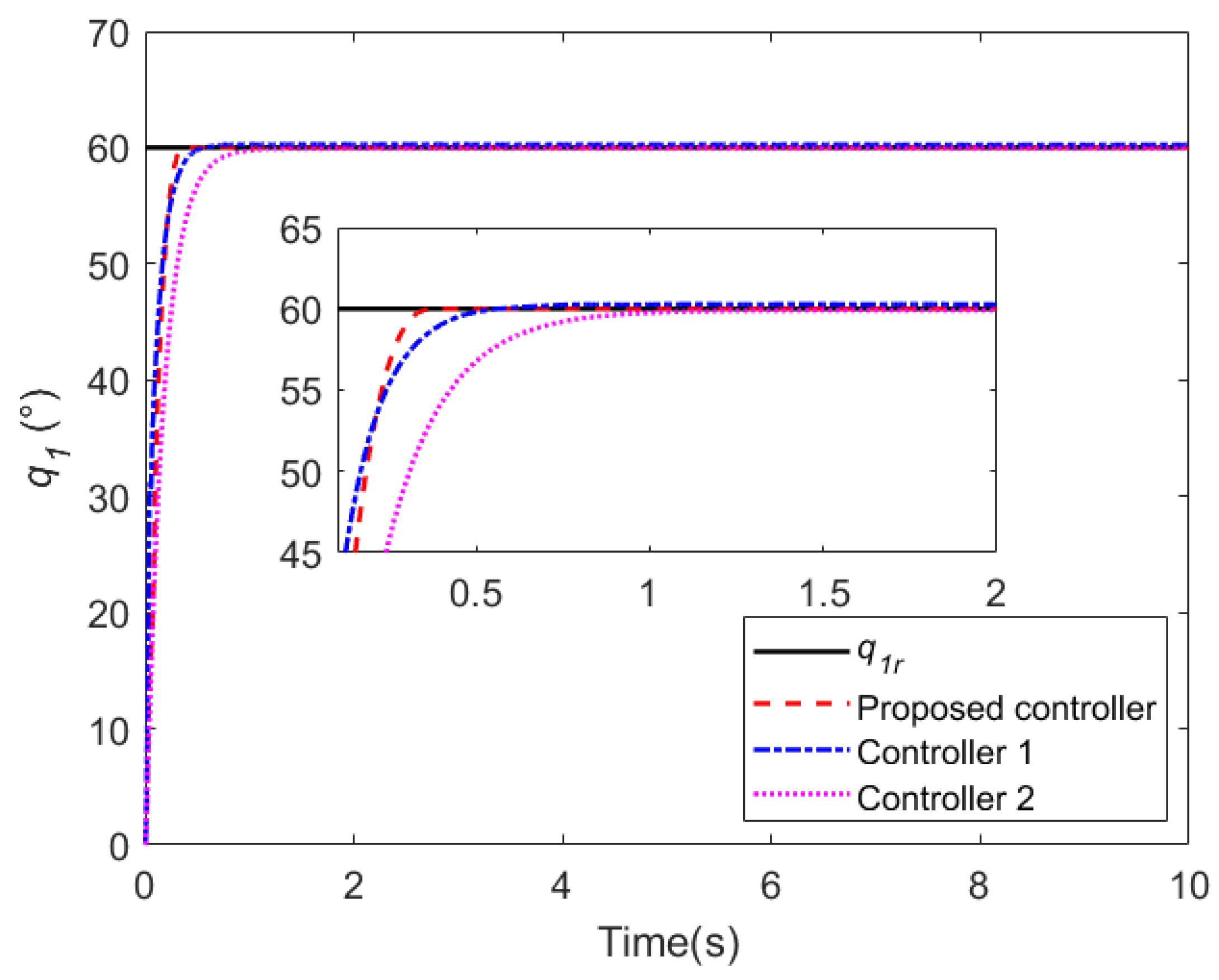
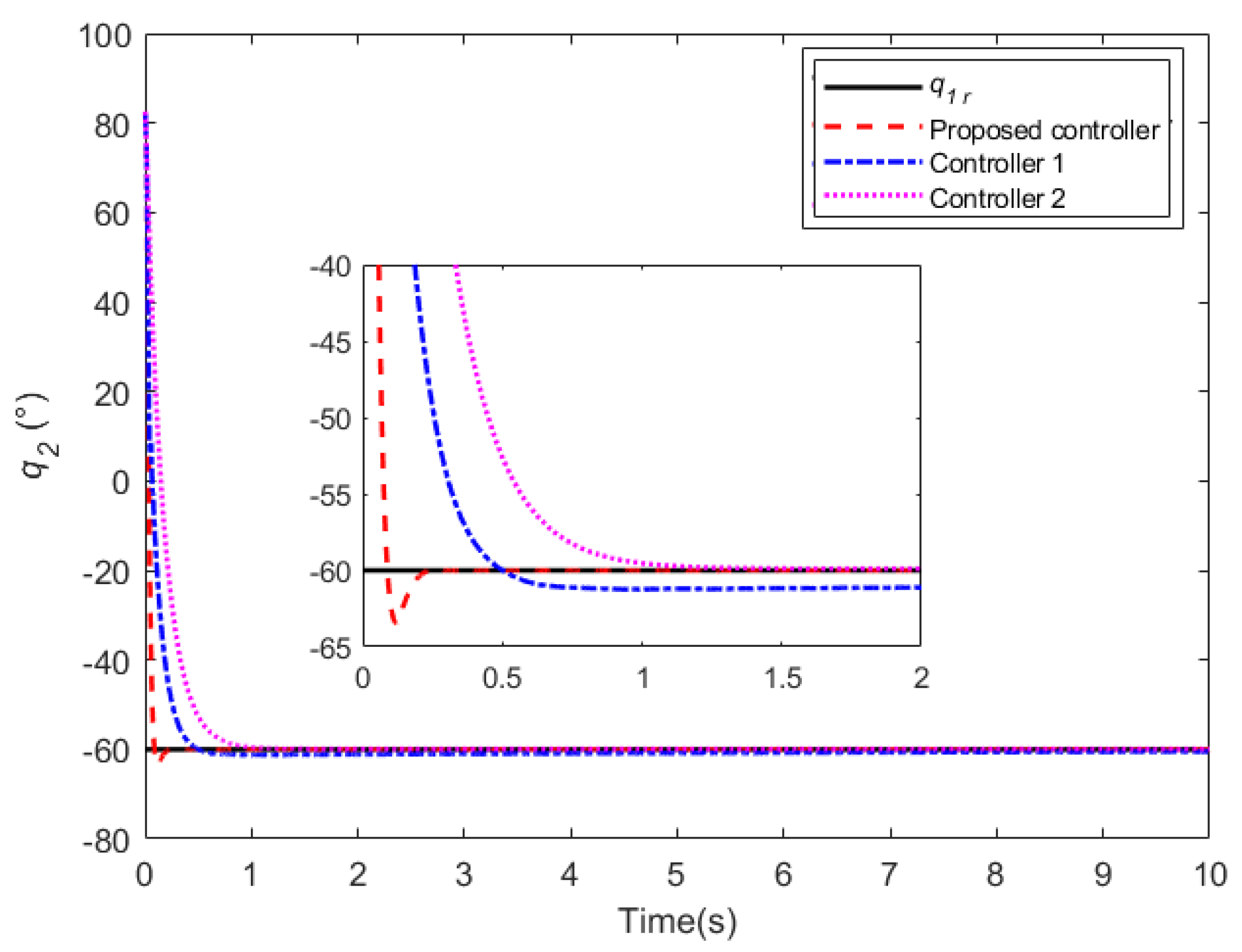
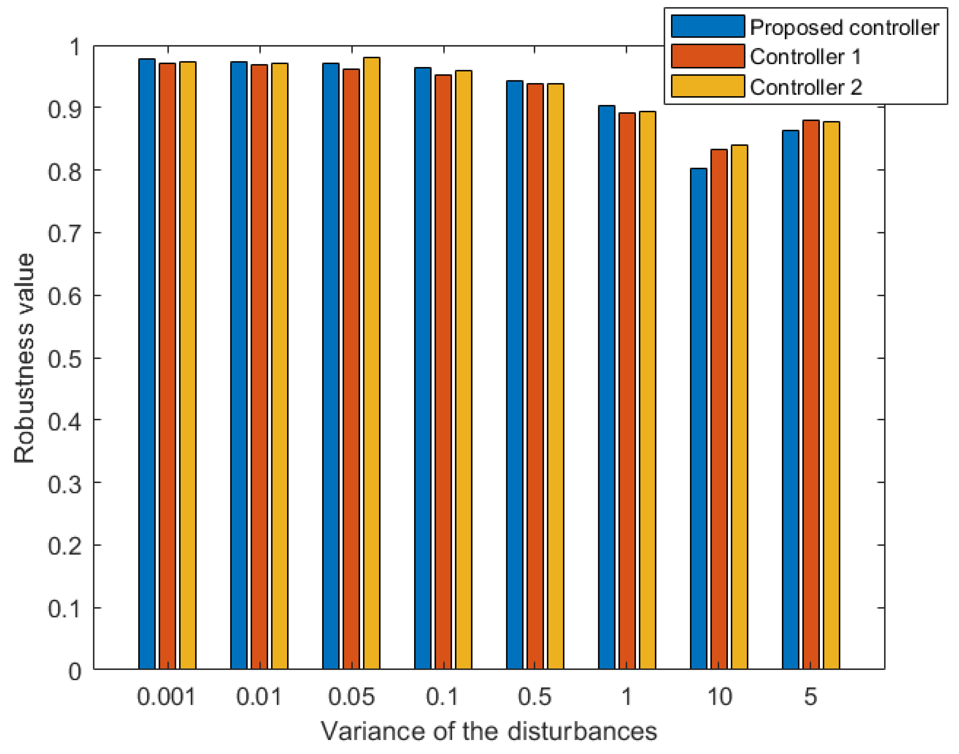
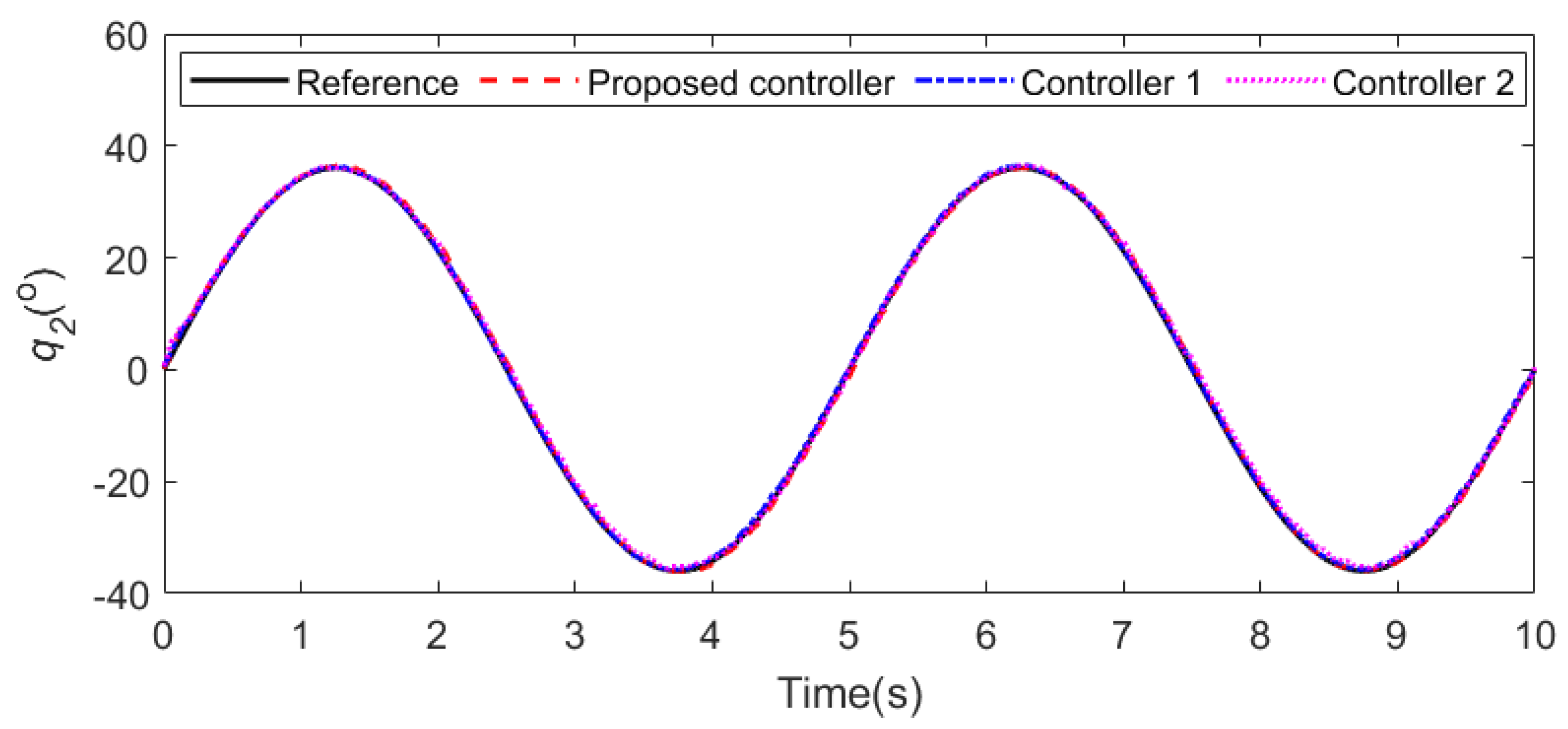
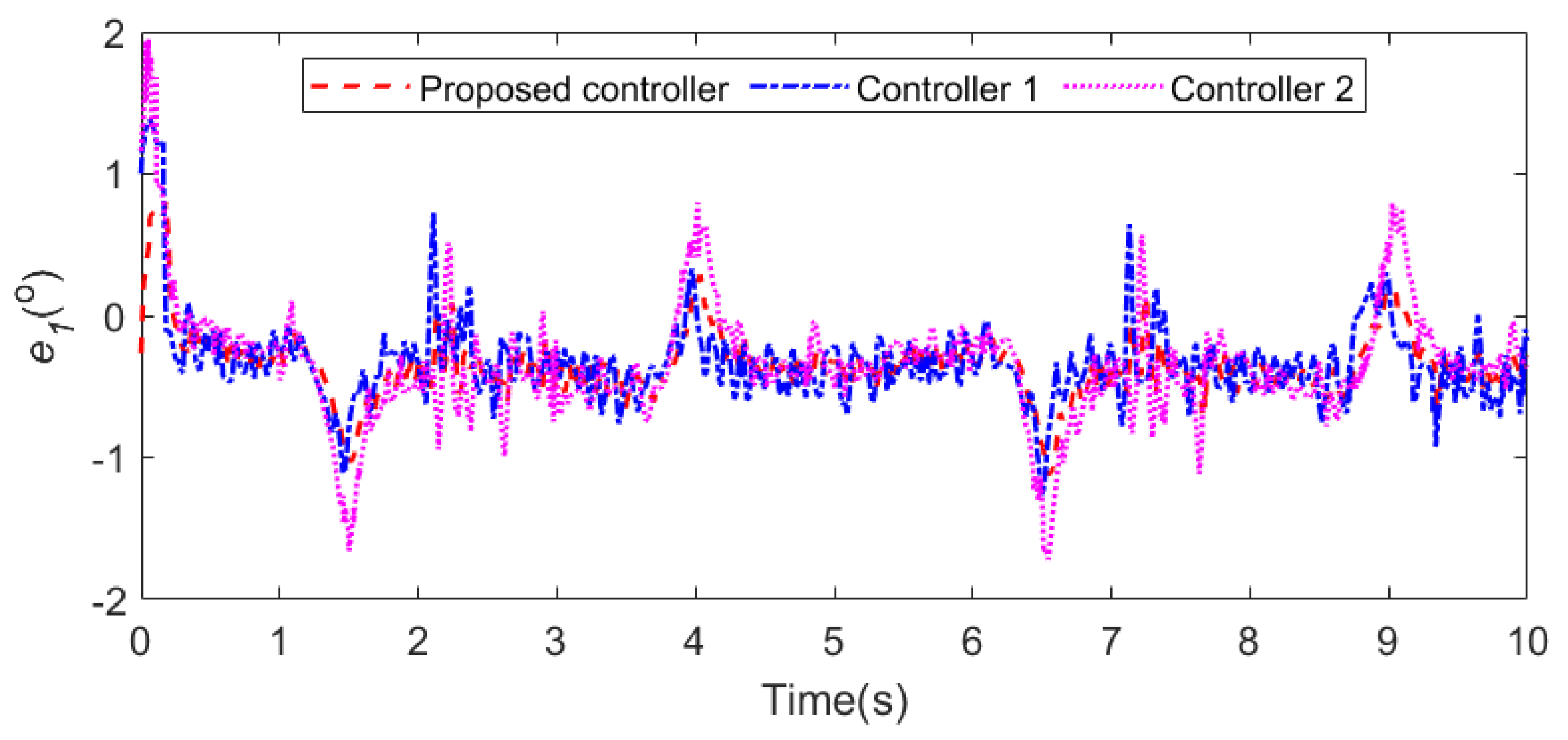
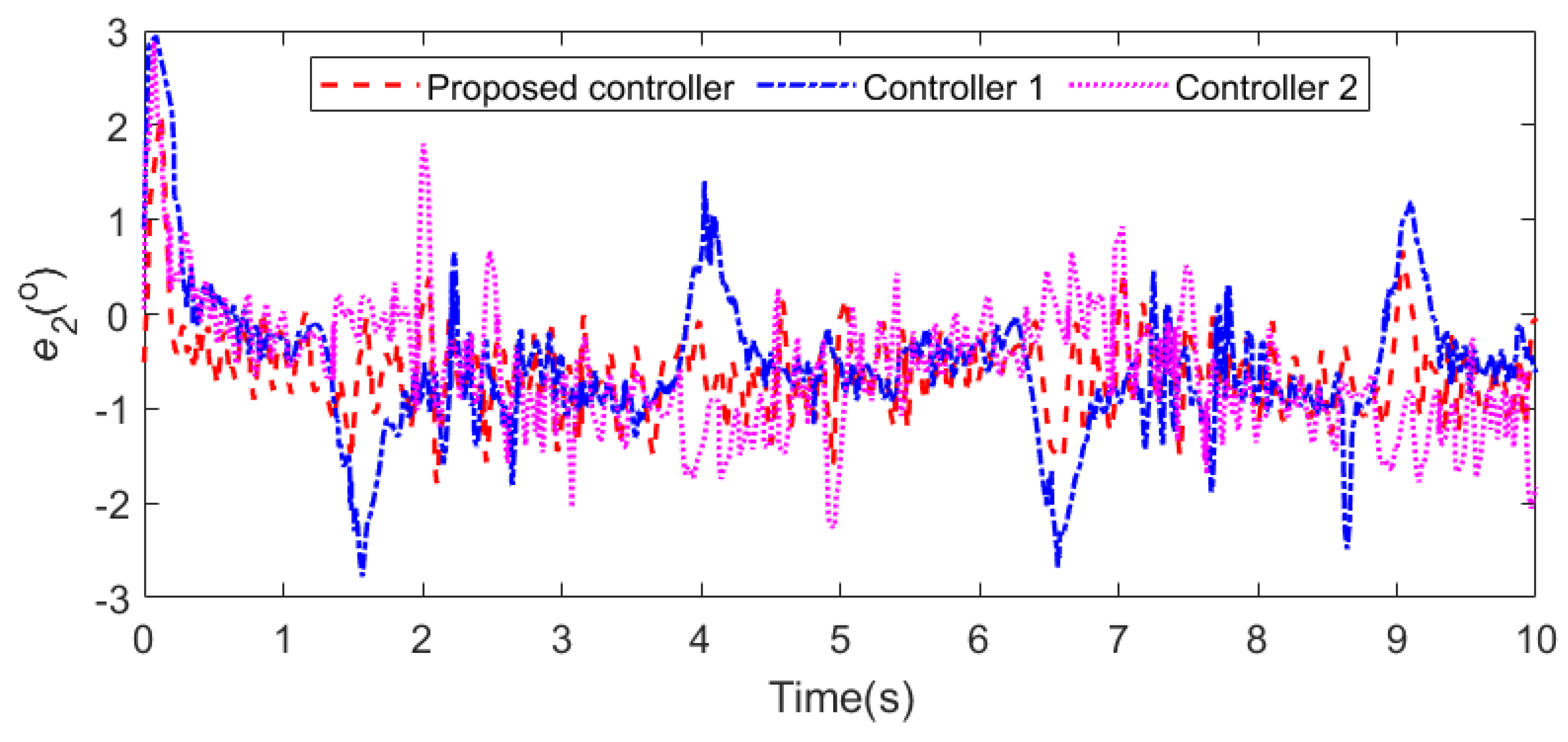
- Compared with SMC schemes [37,38], a backstepping integral fast terminal sliding mode control based on the linear extended state observer (BIFTSMC-LESO) for the cable-driven manipulator is designed for the first time. The hybrid controller ensures that the state quantities can converge in finite time, and has better transient and steady-state performance.
- (iii)
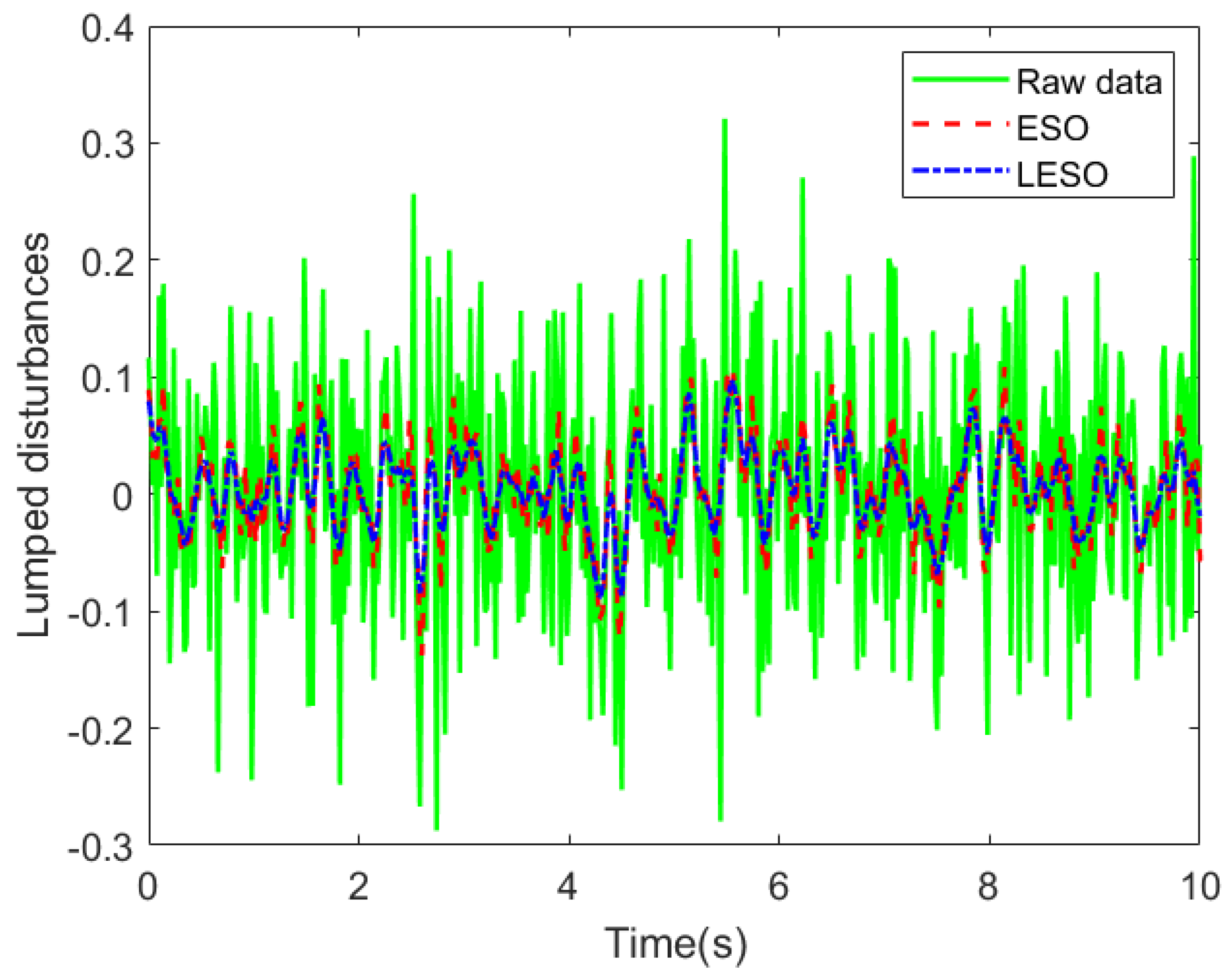
- Several practical factors, such as external disturbances, and internal unmodeled characteristics are considered in our work. We use DOB to observe the lumped disturbances for the quadrotor, and use the LESO to estimate the lumped disturbances for the manipulator, respectively. It can ensure stable tracking without information on the system compared with other controllers [27,39].
2. Mechanical Design
3. System Modeling
4. Controller Design
4.1. Quadrotor Controller Design
4.2. Stability of the Quadrotor Controller
4.3. LESO Design
4.4. Manipulator Controller Design
5. Simulation and Results
5.1. Case 1
5.2. Case 2
5.3. Case 3
6. Conclusions
Author Contributions
Funding
Data Availability Statement
Acknowledgments
Conflicts of Interest
Abbreviations
| AFONTSMC-NDOB | Adaptive fractional-order nonsingular terminal sliding mode based on |
| nonlinear disturbance observer | |
| BC | Backstepping control |
| BIFTSMC-LESO | Backstepping integral fast terminal sliding mode control based on linear |
| extended state observer | |
| BC-DOB | Backstepping based on disturbance observer |
| DOF | Degree-of-freedom |
| DOB | Disturbance observer |
| GPS | Global position system |
| ITSMC | Integral terminal sliding mode control |
| ISSA | Improved salp swarm algorithm |
| LESO | Linear extended state observer |
| LARC | Linear disturbance rejection controller |
| PD | Proportion derivative |
| PID | Proportion integral derivative |
| TSMC | Terminal sliding mode control |
| SMC | Sliding mode control |
| SMC-ESO | Sliding mode control based on extended state observer |
| UAM | Unmanned aerial manipulator |
References
- Hanhauser, E.; Bono, M.S., Jr.; Vaishnav, C.; Hart, A.J.; Karnik, R. Solid-phase extraction, preservation, storage, transport, and analysis of trace contaminants for water quality monitoring of heavy metals. Environ. Sci. Technol. 2020, 54, 2646–2657. [Google Scholar] [CrossRef]
- Ighalo, J.O.; Adeniyi, A.G. A comprehensive review of water quality monitoring and assessment in Nigeria. Chemosphere 2020, 260, 127569. [Google Scholar] [CrossRef]
- Zebral, Y.D.; Righi, B.D.P.; Abou Anni, I.S.; Escarrone, A.L.V.; Roza, M.; Vieira, C.E.D.; Costa, P.G.; Bianchini, A. Pollution levels and biomarker responses in zooplankton from three hydrographic regions of southern Brazil: An integrated approach for water quality monitoring. J. Environ. Chem. Eng. 2021, 9, 106180. [Google Scholar] [CrossRef]
- Bergazin, T.D.; Ben-Shalom, I.Y.; Lim, N.M.; Gill, S.C.; Gilson, M.K.; Mobley, D.L. Enhancing water sampling of buried binding sites using nonequilibrium candidate Monte Carlo. J. Comput. Aided Mol. Des. 2021, 35, 167–177. [Google Scholar] [CrossRef] [PubMed]
- Kose, O.; Oktay, T. Simultaneous design of morphing hexarotor and autopilot system by using deep neural network and SPSA. Aircr. Eng. Aerosp. Technol. 2023, 95, 939–949. [Google Scholar] [CrossRef]
- Khamseh, H.B.; Janabi-Sharifi, F.; Abdessameud, A. Aerial manipulation—A literature survey. Robot. Auton. Syst. 2018, 107, 221–235. [Google Scholar] [CrossRef]
- Ollero, A.; Heredia, G.; Franchi, A.; Antonelli, G.; Kondak, K.; Sanfeliu, A.; Viguria, A.; Martinez-de Dios, J.R.; Pierri, F.; Cortés, J.; et al. The aeroarms project: Aerial robots with advanced manipulation capabilities for inspection and maintenance. IEEE Robot. Autom. Mag. 2018, 25, 12–23. [Google Scholar] [CrossRef]
- Mohiuddin, A.; Tarek, T.; Zweiri, Y.; Gan, D. A survey of single and multi-UAV aerial manipulation. Unmanned Syst. 2020, 8, 119–147. [Google Scholar] [CrossRef]
- Li, L.; Zhang, T.; Zhong, H.; Li, H.; Zhang, H.; Fan, S.; Cao, Y. Autonomous Removing Foreign Objects for Power Transmission Line by Using a Vision-Guided Unmanned Aerial Manipulator. J. Intell. Robot. Syst. 2021, 103, 1–14. [Google Scholar] [CrossRef]
- Kutia, J.R.; Stol, K.A.; Xu, W. Aerial manipulator interactions with trees for canopy sampling. IEEE/ASME Trans. Mechatron. 2018, 23, 1740–1749. [Google Scholar] [CrossRef]
- Kondak, K.; Huber, F.; Schwarzbach, M.; Laiacker, M.; Sommer, D.; Bejar, M.; Ollero, A. Aerial manipulation robot composed of an autonomous helicopter and a 7 degrees of freedom industrial manipulator. In Proceedings of the 2014 IEEE International Conference on Robotics and Automation (ICRA), Hong Kong, China, 31 May–7 June 2014; pp. 2107–2112. [Google Scholar]
- Jimenez-Cano, A.; Heredia, G.; Bejar, M.; Kondak, K.; Ollero, A. Modelling and control of an aerial manipulator consisting of an autonomous helicopter equipped with a multi-link robotic arm. Proc. Inst. Mech. Eng. Part G J. Aerosp. Eng. 2016, 230, 1860–1870. [Google Scholar] [CrossRef]
- Li, J.; Lam, J.; Liu, M.; Wang, Z. Compliant control and compensation for a compact cable-driven robotic manipulator. IEEE Robot. Autom. Lett. 2020, 5, 5417–5424. [Google Scholar] [CrossRef]
- Wang, Y.; Zhu, K.; Chen, B.; Jin, M. Model-free continuous nonsingular fast terminal sliding mode control for cable-driven manipulators. ISA Trans. 2020, 98, 483–495. [Google Scholar] [CrossRef] [PubMed]
- Xu, W.; Liu, T.; Li, Y. Kinematics, dynamics, and control of a cable-driven hyper-redundant manipulator. IEEE/ASME Trans. Mechatron. 2018, 23, 1693–1704. [Google Scholar] [CrossRef]
- Ruggiero, F.; Lippiello, V.; Ollero, A. Aerial manipulation: A literature review. IEEE Robot. Autom. Lett. 2018, 3, 1957–1964. [Google Scholar] [CrossRef]
- Abaunza, H.; Castillo, P.; Victorino, A.; Lozano, R. Dual quaternion modeling and control of a quad-rotor aerial manipulator. J. Intell. Robot. Syst. 2017, 88, 267. [Google Scholar] [CrossRef]
- Kuciński, T.; Rybus, T.; Seweryn, K.; Banaszkiewicz, M.; Buratowski, T.; Chmaj, G.; Grygorczuk, J.; Uhl, T. Deployable manipulator technology with application for UAVs. In Aerospace Robotics II; Springer: Berlin/Heidelberg, Germany, 2015; pp. 93–103. [Google Scholar]
- Orsag, M.; Korpela, C.M.; Bogdan, S.; Oh, P.Y. Hybrid adaptive control for aerial manipulation. J. Intell. Robot. Syst. 2014, 73, 693–707. [Google Scholar] [CrossRef]
- Kannan, S.; Olivares-Mendez, M.A.; Voos, H. Modeling and control of aerial manipulation vehicle with visual sensor. IFAC Proc. Vol. 2013, 46, 303–309. [Google Scholar] [CrossRef]
- Kannan, S.; Alma, M.; Olivares-Mendez, M.A.; Voos, H. Adaptive control of aerial manipulation vehicle. In Proceedings of the 2014 IEEE International Conference on Control System, Computing and Engineering (ICCSCE 2014), Penang, Malaysia, 28–30 November 2014; pp. 273–278. [Google Scholar]
- Jimenez-Cano, A.E.; Martin, J.; Heredia, G.; Ollero, A.; Cano, R. Control of an aerial robot with multi-link arm for assembly tasks. In Proceedings of the 2013 IEEE International Conference on Robotics and Automation, Karlsruhe, Germany, 6–10 May 2013; pp. 4916–4921. [Google Scholar]
- Song, B.; Liu, Y.; Fan, C. Feedback linearization of the nonlinear model of a small-scale helicopter. J. Control Theory Appl. 2010, 8, 301–308. [Google Scholar] [CrossRef]
- Yang, B.; He, Y.; Han, J.; Liu, G. Rotor-flying manipulator: Modeling, analysis, and control. Math. Probl. Eng. 2014, 2014, 492965. [Google Scholar] [CrossRef]
- Imanberdiyev, N.; Kayacan, E. A fast learning control strategy for unmanned aerial manipulators. J. Intell. Robot. Syst. 2019, 94, 805–824. [Google Scholar] [CrossRef]
- Samadikhoshkho, Z.; Ghorbani, S.; Janabi-Sharifi, F.; Zareinia, K. Nonlinear control of aerial manipulation systems. Aerosp. Sci. Technol. 2020, 104, 105945. [Google Scholar] [CrossRef]
- Emami, S.A.; Banazadeh, A. Simultaneous trajectory tracking and aerial manipulation using a multi-stage model predictive control. Aerosp. Sci. Technol. 2021, 112, 106573. [Google Scholar] [CrossRef]
- Riache, S.; Kidouche, M.; Rezoug, A. Adaptive robust nonsingular terminal sliding mode design controller for quadrotor aerial manipulator. TELKOMNIKA (Telecommun. Comput. Electron. Control) 2019, 17, 1501–1512. [Google Scholar] [CrossRef]
- Ma, Z.; Sun, G. Dual terminal sliding mode control design for rigid robotic manipulator. J. Frankl. Inst. 2018, 355, 9127–9149. [Google Scholar] [CrossRef]
- Yi, S.; Zhai, J. Adaptive second-order fast nonsingular terminal sliding mode control for robotic manipulators. ISA Trans. 2019, 90, 41–51. [Google Scholar] [CrossRef]
- Qiao, L.; Zhang, W. Trajectory tracking control of AUVs via adaptive fast nonsingular integral terminal sliding mode control. IEEE Trans. Ind. Inform. 2019, 16, 1248–1258. [Google Scholar] [CrossRef]
- Müller, D.; Veil, C.; Sawodny, O. Disturbance observer based control for quasi continuum manipulators. IFAC-PapersOnLine 2020, 53, 9808–9813. [Google Scholar] [CrossRef]
- Homayounzade, M.; Khademhosseini, A. Disturbance observer-based trajectory following control of robot manipulators. Int. J. Control Autom. Syst. 2019, 17, 203–211. [Google Scholar] [CrossRef]
- Wang, Y.; Ma, Y.; Cai, Z.; Zhao, J. Quadrotor trajectory tracking and obstacle avoidance by chaotic grey wolf optimization-based backstepping control with sliding mode extended state observer. Trans. Inst. Meas. Control 2020, 42, 1675–1689. [Google Scholar] [CrossRef]
- Deng, W.; Yao, J. Extended-state-observer-based adaptive control of electrohydraulic servomechanisms without velocity measurement. IEEE/ASME Trans. Mechatron. 2019, 25, 1151–1161. [Google Scholar] [CrossRef]
- Zhang, J.; Feng, J.; Zhou, Y.; Fang, F.; Yue, H. Linear active disturbance rejection control of waste heat recovery systems with organic Rankine cycles. Energies 2012, 5, 5111–5125. [Google Scholar] [CrossRef]
- Bouzgou, K.; Benchikh, L.; Nouveliere, L.; Ahmed-Foitih, Z. PD sliding mode controller based decoupled aerial manipulation. In Proceedings of the 17th International Conference on Informatics in Control, Automation and Robotics (ICINCO 2020), Paris, France, 7–9 July 2020; pp. 484–489. [Google Scholar]
- Xu, W.; Cao, L.; Peng, B.; Wang, L.; Gen, C.; Liu, Y. Adaptive Nonsingular Fast Terminal Sliding Mode Control of Aerial Manipulation Based on Nonlinear Disturbance Observer. Drones 2023, 7, 88. [Google Scholar] [CrossRef]
- Khamseh, H.B.; Ghorbani, S.; Janabi-Sharifi, F. Unscented Kalman filter state estimation for manipulating unmanned aerial vehicles. Aerosp. Sci. Technol. 2019, 92, 446–463. [Google Scholar] [CrossRef]
- Mellinger, D.; Kumar, V. Minimum snap trajectory generation and control for quadrotors. In Proceedings of the 2011 IEEE International Conference on Robotics and Automation, Shanghai, China, 9–13 May 2011; pp. 2520–2525. [Google Scholar]
- Idrissi, M.; Salami, M.; Annaz, F. A review of quadrotor unmanned aerial vehicles: Applications, architectural design and control algorithms. J. Intell. Robot. Syst. 2022, 104, 22–33. [Google Scholar] [CrossRef]
- Dong, W.; Gu, G.Y.; Zhu, X.; Ding, H. High-performance trajectory tracking control of a quadrotor with disturbance observer. Sens. Actuators A Phys. 2014, 211, 67–77. [Google Scholar] [CrossRef]
- Dong, W.; Gu, G.Y.; Zhu, X.; Ding, H. Development of a quadrotor test bed—Modelling, parameter identification, controller design and trajectory generation. Int. J. Adv. Robot. Syst. 2015, 12, 7. [Google Scholar] [CrossRef]
- Yang, Z.J.; Tsubakihara, H.; Kanae, S.; Wada, K.; Su, C.Y. A novel robust nonlinear motion controller with disturbance observer. IEEE Trans. Control Syst. Technol. 2007, 16, 137–147. [Google Scholar] [CrossRef]
- Park, J.H.; Park, G.T. Adaptive fuzzy observer with minimal dynamic order for uncertain nonlinear systems. IEE Proc. Control Theory Appl. 2003, 150, 189–197. [Google Scholar] [CrossRef]
- Ding, L.; Li, Y. Optimal attitude tracking control for an unmanned aerial quadrotor under lumped disturbances. Int. J. Micro Air Veh. 2020, 12, 1756829320923563. [Google Scholar] [CrossRef]
- Truong, T.N.; Vo, A.T.; Kang, H.J. A backstepping global fast terminal sliding mode control for trajectory tracking control of industrial robotic manipulators. IEEE Access 2021, 9, 31921–31931. [Google Scholar] [CrossRef]
- Ding, L.; Wu, H. Dynamical modelling and robust control for an unmanned aerial robot using hexarotor with 2-DOF manipulator. Int. J. Aerosp. Eng. 2019, 2019, 1–12. [Google Scholar] [CrossRef]
- Ding, L.; Ma, R.; Wu, Z.; Qi, R.; Ruan, W. Optimal Joint Space Control of a Cable-Driven Aerial Manipulator. CMES Comput. Model. Eng. Sci. 2023, 135, 441–464. [Google Scholar] [CrossRef]
- Abe, A.; Hashimoto, K. A novel feedforward control technique for a flexible dual manipulator. Robot. Comput.-Integr. Manuf. 2015, 35, 169–177. [Google Scholar] [CrossRef]




| Parameter | Value | Explanation | Parameter | Value | Explanation |
|---|---|---|---|---|---|
| m | 3 kg | Mass of the quadrotor | m | 0.06 kg | Mass of the link 1 |
| m | 0.225 kg | Mass of link 2 | g | 9.8 m/s | Gravitational acceleration |
| l | 0.05 m | Length of link 1 | l | 0.15 m | Length of link 2 |
| J | 0.287 kg·m | Rotational inertia of the quadrotor around the x-axis | J | 0.314 kg·m | Rotational inertia of the quadrotor around the y-axis |
| J | 0.1477 kg·m | Rotational inertia of the quadrotor around the z-axis | I | 0.102 kg·m | Inertia of motor 1 |
| I | 0.811 kg·m | Inertia of motor 2 | D | 0.001 kg·m | Damp of motor 1 |
| D | 0.001 kg·m | Damp of motor 2 | L | 0.630 m | Distance between the rotation axes and center of quadrotor |
| k | 1.1719 × 10 | Thrust coefficient | k | 0.198 × 10 | Torque coefficient |
| Parameter | Value | Parameter | Value |
|---|---|---|---|
| 401 | 380 | ||
| 2 | 1 | ||
| 3 | 2 | ||
| 1 | 1 | ||
| 1 | 1 | ||
| k | 0.5 | k | 0.5 |
| Parameter | Value | Parameter | Value |
|---|---|---|---|
| 120 | 96 | ||
| 303 | 316 | ||
| 800 | 780 | ||
| 0.5 | 0.5 | ||
| 0.5 | 0.5 | ||
| 0.02 | 0.02 | ||
| k | 87 | k | 79 |
| c | 1.5 | c | 1.5 |
| Parameter | Value | Parameter | Value |
|---|---|---|---|
| 500 | 500 | ||
| 39 | 45 |
| Parameter | Value |
|---|---|
| [5,5,2] | |
| [0.02,0.02,0.01] | |
| [10,10,8] | |
| [6,7,1] | |
| [1,1,0.5] |
Disclaimer/Publisher’s Note: The statements, opinions and data contained in all publications are solely those of the individual author(s) and contributor(s) and not of MDPI and/or the editor(s). MDPI and/or the editor(s) disclaim responsibility for any injury to people or property resulting from any ideas, methods, instructions or products referred to in the content. |
© 2023 by the authors. Licensee MDPI, Basel, Switzerland. This article is an open access article distributed under the terms and conditions of the Creative Commons Attribution (CC BY) license (https://creativecommons.org/licenses/by/4.0/).
Share and Cite
Ding, L.; Zhu, G.; Li, Y.; Wang, Y. Cable-Driven Unmanned Aerial Manipulator Systems for Water Sampling: Design, Modeling, and Control. Drones 2023, 7, 450. https://doi.org/10.3390/drones7070450
Ding L, Zhu G, Li Y, Wang Y. Cable-Driven Unmanned Aerial Manipulator Systems for Water Sampling: Design, Modeling, and Control. Drones. 2023; 7(7):450. https://doi.org/10.3390/drones7070450
Chicago/Turabian StyleDing, Li, Guibing Zhu, Yangmin Li, and Yaoyao Wang. 2023. "Cable-Driven Unmanned Aerial Manipulator Systems for Water Sampling: Design, Modeling, and Control" Drones 7, no. 7: 450. https://doi.org/10.3390/drones7070450
APA StyleDing, L., Zhu, G., Li, Y., & Wang, Y. (2023). Cable-Driven Unmanned Aerial Manipulator Systems for Water Sampling: Design, Modeling, and Control. Drones, 7(7), 450. https://doi.org/10.3390/drones7070450


