Article

Intelligent Swarm: Concept, Design and Validation of Self-Organized UAVs Based on Leader–Followers Paradigm for Autonomous Mission Planning

by
Wilfried Yves Hamilton Adoni
1,2,*,†,
Junaidh Shaik Fareedh
2,†,
Sandra Lorenz
2,
Richard Gloaguen
2,
Yuleika Madriz
2,
Aastha Singh
2 and
Thomas D. Kühne
1
1
Helmholtz-Zentrum Dresden-Rossendorf, Center for Advanced Systems Understanding, Untermarkt 20, 02826 Görlitz, Germany
2
Helmholtz-Zentrum Dresden-Rossendorf, Helmholtz Institute Freiberg for Resource Technology, Chemnitzer Str. 40, 09599 Freiberg, Germany
*
Author to whom correspondence should be addressed.
These authors contributed equally to this work.
Drones 2024, 8(10), 575; https://doi.org/10.3390/drones8100575
Submission received: 15 August 2024 / Revised: 29 September 2024 / Accepted: 7 October 2024 / Published: 11 October 2024
(This article belongs to the Special Issue Distributed Control, Optimization, and Game of UAV Swarm Systems)

Abstract

:
Unmanned Aerial Vehicles (UAVs), commonly known as drones, are omnipresent and have grown in popularity due to their wide potential use in many civilian sectors. Equipped with sophisticated sensors and communication devices, drones can potentially form a multi-UAV system, also called an autonomous swarm, in which UAVs work together with little or no operator control. According to the complexity of the mission and coverage area, swarm operations require important considerations regarding the intelligence and self-organization of the UAVs. Factors including the types of drones, the communication protocol and architecture, task planning, consensus control, and many other swarm mobility considerations must be investigated. While several papers highlight the use cases for UAV swarms, there is a lack of research that addresses in depth the challenges posed by deploying an intelligent UAV swarm. Against this backdrop, we propose a computation framework of a self-organized swarm for autonomous and collaborative missions. The proposed approach is based on the Leader–Followers paradigm, which involves the distribution of ROS nodes among follower UAVs, while leaders perform supervision. Additionally, we have integrated background services that autonomously manage the complexities relating to task coordination, control policy, and failure management. In comparison with several research efforts, the proposed multi-UAV system is more autonomous and resilient since it can recover swiftly from system failure. It is also reliable and has been deployed on real UAVs for outdoor survey missions. This validates the applicability of the theoretical underpinnings of the proposed swarming concept. Experimental tests carried out as part of an area coverage mission with 6 quadcopters (2 leaders and 4 followers) reveal that the proposed swarming concept is very promising and inspiring for aerial vehicle technology. Compared with the conventional planning approach, the results are highly satisfactory, highlighting a significant gain in terms of flight time, and enabling missions to be achieved rapidly while optimizing energy consumption. This gives the advantage of exploring large areas without having to make frequent downtime to recharge and/or charge the batteries. This manuscript has the potential to be extremely useful for future research into the application of unmanned swarms for autonomous missions.

1. Introduction

Unmanned Aerial Vehicles (UAVs), commonly known as drones [1], are gaining popularity in academic and industry research due to advances in sensing and computational abilities, as well as reductions in size and operational costs. UAVs play an important role in industrial sector [2] such as surveys [3], natural disasters [4,5,6,7], forestry fire control [8], agriculture [9,10], transportation [11,12,13], and the field of geology [14]. For example, they enable one to carry out missions in dangerous environments or those difficult for humans to access [15,16,17,18]. In the agricultural sector [9], drones are frequently used for spraying plantations and gathering information that has an impact on crop yield quality and quantity, thanks to their ability to scan planting zones quickly. They are also used for forest mapping and soil heterogeneity analysis [10]. This research solely focuses on civilian use and, while we cannot discard potential indirect use for military purposes, this research is intended to improve the well-being of humankind.
UAVs offer a wide range of possibilities in the healthcare sector, including the delivery of medical equipment, blood samples, or laboratory results to isolated or hard-to-reach areas [19]. They are also used for parcel delivery [13,20,21], road traffic monitoring [12], and mapping volcanic terrain or seismic activity to predict and elaborate rescue operations in case of potential eruptions or natural disasters [4,5,6,14]. Because the first few hours after a disaster are crucial, it is when there is the best chance of saving people’s lives. In numerous catastrophe situations, such as earthquakes, avalanches, landslides, and fires, injured people need to rapidly localize for immediate medical assistance [6,7]. In this context, all available rescue teams must focus on the search and rescue mission. Rescue operations must be orchestrated, and the disaster’s impact must be identified as soon as feasible [5]. Time constraints, a lack of rescue staff, and an urgent need for information are more than enough reasons to justify the employment of drones that operate independently to gather as much information as possible and offer communication across the impacted regions [6].
This growing interest in drones has spawned the emergence of numerous types of UAVs with diverse designs and components in terms of dimension and form. They are classified into the following categories, rotor, fixed-wing, and hybrid, and they vary in size from small and medium to large [11]. Small drones, also known as micro- or nano-UAVs, refer to lightweight aerial vehicles [2,11] that have extended the limits of their applications even further. The portability and speed of micro-UAVs provide a plethora of advantageous applications [22,23,24,25]. They are more agile, allowing them to fly through narrow spaces and reduce potential collateral incidents due to their tiny weight and dimensions (between 30 and 200 cm 2 ). However, drones also pose a security issue that must be addressed [26,27]. Intrusions into protected airspace or inhabited areas must be dealt with in a safe, noninvasive manner to safeguard the area of interest, especially when public security is at stake. Particularly, Counter-Unmanned Aerial Systems (C-UASs) [28] might aid in the monitoring of industrial areas, hospitals, airports, and public domains such as forests or natural reserves [11,29]. Furthermore, the size of UAVs restricts their capabilities in terms of flight time, onboard sensor and computation energy, and payload, reducing the jobs that they can accomplish independently. This has led to the emergence of drone swarms or multi-UAV systems, in which several UAVs work together in hierarchical groups to overcome the limits of individual UAVs. Multi-UAV systems are a key example of multiagent systems [30]. They can complete missions that individual drones cannot. Another benefit of drone swarms is that they can accomplish many distributed tasks at once [11].
The advancement of technologies like onboard computer vision and autonomous capabilities [31] can boost the use of aerial swarms in a wider range of applications [13,32]. For example, they can collectively lift a hefty payload, while remaining far nimbler and more stable than a single larger drone [22,33]. A swarm can investigate unknown regions in search and rescue missions by traversing in a distributed manner multiple distinct pathways that, when combined, cover the entire region quickly [6,20,34,35]. They not only can help to determine the precise location where a portable device’s received signal is strongest, but they can also map the area and even acquire infrared scans to detect the body heat of victims otherwise left in the rubble. To perform this, drones must operate as quickly as possible and in a self-organizing way. The less time we take to assess the damage and identify victims, the greater our probability of rescuing individuals [36]. The usage of aerial swarms to tackle real-world issues has expanded gradually as prices have dropped and the effectiveness of communications, detection, and computation hardware has gotten better. The standardization of hardware has reduced the unit costs of components such as batteries, propellers, motors, radio transmitters, cameras, sensors, and many others. This has helped to popularize the use of drones, as well as lowering the barriers to their use in aerial swarm robotics.
UAV swarms are designed as completely distributed systems in which each drone analyzes the local perception of its environment and collaborates with others to carry out individual actions that collectively contribute to the achievement of an overall swarm goal [37]. These collaborative operations may be modeled as an optimization problem of path cost, i.e., a cost function based on the UAVs’ whereabouts and, eventually, information about their surroundings [36]. The design of Unmanned Aerial Systems (UASs) necessitates the tight integration of several components, such as global and relative localization, safe mission planning, and swarm-level synchronization of actions and movements. The operating principle of swarms is based on a family of algorithms that enable each swarm unit to communicate and delegate mission duties, plan trajectories, and coordinate flying to efficiently achieve the swarm’s overall objectives [36]. These algorithms generally operate in a highly hierarchical architecture, giving the swarm some autonomy at different levels. As a result, the human operator’s responsibility may be limited to basic oversight and higher-level engagement without direct action. This architecture depends on the environment, the complexity of the mission, the control consensus [38,39,40], energy consumption [5,23,34,41,42], and the communication topology [11,37]. We address these challenges in the present contribution. In this manuscript, we focus on the key aspects that concern the design architecture and deployment of a fully autonomous and hierarchical swarm for collaborative missions:
  • Mission planning: Unlike single-UAV systems, missions performed by multi-UAV systems are executed in a parallel and distributed manner to be completed faster [1]. This paradigm of computation involves two main challenges. The first challenge concerns the partition of the exploration environment into subareas. Depending on the homogeneity of the swarm, each area must be assigned to a UAV with respect to their local perception. This becomes even more difficult when dealing with a nonhomogeneous swarm operating in a dynamic environment. The second challenge relates to the collaborative execution of distributed tasks. Tasks must be allocated adaptively to allow for a high degree of parallelism if the UAVs are heterogeneous [11]. Alternatively, it will be handled based on the workload and computational capabilities of each UAV. In addition, the execution of the mission must be based on a consensus control [38,39,40] that promotes collaborative decision making in which the tasks carried out by the UAVs make it possible to converge towards a common goal.
  • Mobility: Navigation of the UAVs inside the swarm is organized in a tight formation [11,31,43,44]. Sometimes the swarm is organized hierarchically, according to the type of mission or action performed by each UAV. Issues emerge when the relative locations and directions of the UAVs vary. The difficulties to be addressed include avoiding crashes and collisions, obstruction detection, and signal stability within the swarm [11,45].
  • Communication: A single UAV must maintain a constant connection with the ground control station. A multi-UAV system, on the other hand, may have a unique UAV (gateway UAV) [11] that communicates with the ground control station and relays the messages to other UAVs [1]. The communication in the swarm is challenging because of the high mobility of the UAVs. To ensure a good communication signal, drones should be close to each other. The multi-UAV systems must guarantee interoperability in case the swarm consists of various types of drones independent of their communication protocols [11]. In an outdoor environment, interferences can disrupt communication and therefore, hamper the mission [26].
  • Energy consumption: Due to the small size of the drones, they cannot carry a substantial power supply [34]. Power limitations impact swarm communication, mobility, and flight time. Therefore, the coverage paths and the collaborative tasks must be optimized to significantly reduce the energy consumption of the UAV fleet [5,11]. This task is challenging and involves two major factors: (1) communication energy used for signal processing, routing protocol, and packet transmission of embedded sensors and (2) propulsion energy used to ensure drone mobility (speed, acceleration, propulsion type, altitude, and so on.) depending on load capacity and mission types.
  • Resilience: In a single-UAV scenario, if the running instance is stopped because of software or hardware failure, the mission fails [1]. Multi-UAV systems should avoid single point of failure (SPOF) because they need high availability and fault tolerance against running issues and hardware failure. If one UAV of the swarm is stopped, the mission must continue to operate on another available UAV, assuming downtime. It is challenging to implement a disaster recovery mechanism that describes how the swarm can continue to operate when a failure appears in multi-UAV systems. This is a three-stage process, and a few factors need to be considered, including the following: (1) Problem identification: This could be a collision, a crash, equipment or sensor failure, or bugs. (2) Drone selection: In the second step, we determine which drone will be tasked with continuing the execution of the failed task. (3) Business continuity: This involves determining the status of the mission to restart where the execution failed or go to fail-safe procedures (safe termination of the mission).
Contributions: The main objective of this study is to offer a framework for the conception and implementation of a fully autonomous multi-UAV system based on the Leader–Followers paradigm [46]. To fulfill the envisioned missions, the proposed system is distributed and handles several tasks at once allowing the aerial swarm to complete missions rapidly. Moreover, the communication occurs within a decentralized single-group architecture that encourages UAV-to-UAV interactions within the swarm, bypassing conventional centralized communication models that rely on a ground control station (GCS) [11]. Furthermore, the proposed system supports scalability so that we can add or remove UAVs from the swarm without network reconfiguration. It is also resilient and can continue operating in the event of a drone failure or bugs occurring during the execution of a task, even if there is a crash or collision.
Innovations: By leveraging the most recent breakthroughs in the literature review, this research bridges gaps in the implementation from scratch of a resilient, fully autonomous aerial swarm for autonomous and cooperative missions. More particularly, the following points emphasize the key added value of this work:
  • Because the area of autonomous aerial systems is still in its early stages, there is a scarcity of formal understanding of swarm intelligence. There is a lack of stable, reliable, and scalable multi-UAV system architecture that supports the collaborative actions of self-organized swarms. In this regard, our research provides substantial value by filling the gap in the design of actions performed by an autonomous swarm.
  • In most research, multi-UAV systems rely on a centralized communication infrastructure at the GCS. In this sense, the added value of our communication model is that it is based on a decentralized single-group architecture that can be extended to a multigroup one [11]. Thus, we suggest removing the dependency from the GCS and promoting UAV-to-UAV communication without operator involvement. This communication infrastructure is rarely implemented in existing works because of its susceptibility to failure, which we must address.
  • The study of intelligence and collaboration inside an autonomous swarm is challenging, with relatively few papers that completely investigate the complexities of how they operate. For example, the problem of the high availability (HA) and resilience of UAVs is not addressed in most works. Added to this, there is a lack of tracking and control of the mission being carried out in the swarm. To compensate for these omissions, we integrate a swarm management policy, and local rules based on consensus control, resulting in a scientific contribution that brings valuable knowledge to bear on the question of how to ensure high availability, fault tolerance, and resiliency when a UAV breaks down or in the event of bugs/collisions. We have proposed a series of ROS services that run continuously to ensure the proper functioning of a multi-UAV system.

2. Background and Existing Works

The usage of aerial swarms to tackle real-world issues has expanded gradually as prices have dropped and the effectiveness of communications, detection, and computation hardware has gotten better. The standardization of hardware has reduced the unit costs of components such as batteries, propellers, motors, radio transmitters, cameras, sensors, and many others. This has helped to popularize the swarming concept, as well as lowering the barriers to their use in aerial swarm robotics. This idea has been demonstrated to reduce mission time and increase satisfaction rates, especially for arduous operations. Although individual UAVs have been extensively researched in the literature and have found numerous applications, there are limits that may be only addressed by utilizing aerial swarms [6,20,22,33,34,35,36].

2.1. Swarm Intelligence

An intelligent UAV swarm is a fleet of autonomous UAVs working together according to a rule set for coordination, communication, and collaboration, with the aim of efficiently carrying out a complex mission without human intervention [47]. Unlike a single UAV system, their management involves challenges linked to the dynamic allocation of mission tasks but also risks of collision and loss of communication signal. Researchers have been very interested in this field of study for the past ten years because of the wide range of industrial [11] and civilian application [11,37] it has, such as emergency rescue and [6,7,16], investigation [48,49], as well as intelligent [22,25,50], agriculture [9,10] and delivery services [19,51]. Swarms are distinguished from multiagent UAVs [38,40] by a set of requirements, such as the existence of a minimum of three agents and a share of pertinent information like position, velocity, and state, among others [4,30]. Each UAV needs to be adapted and comply with the same set of defined consensuses that controls the whole swarm [35,38]. Furthermore, system stability and safety must not be affected when a drone is faulty or disconnected from the swarm.
In an intelligent swarm, the drones’ behavior is a key concern, as it involves the actions they perform, their interactions, and their local perceptions of the environment [11,52]. Muhammad et al. [38] characterized the fundamental behaviors of swarm UAVs by individual agents obeying local rules based on consensus control, which leads to an evolution towards global behavior through interactions to perform collective decision making. Collective decision making allows performing distributed tasks cooperatively in the swarm [11]. In [37], Schranz et al. presented a more detailed taxonomy of swarm behaviors that impact collective decision making:
  • Collective fault detection detects individual UAV flaws with the swarm, allowing the identification of possible drones that deviate from the swarm’s expected behavior due to hardware failures or computational issues [47,53].
  • Task allocation enables emerging tasks to be distributed dynamically between the different UAVs in the swarm. Its purpose is to enhance the overall effectiveness of the swarming system [37,48]. If the swarm is homogeneous, the tasks can be allocated equitably. When the UAVs have different capabilities, the tasks may be allocated according to the workload capacity of each UAV [11,37].
  • Consensus control enables the UAVs within the swarm to converge and settle toward a single common decision among multiple choices [37,39,47].
  • Collective perception merges the data perceived locally by the swarm’s UAVs into a complete image of the environment. It enables the swarm to make collective actions, such as multitarget tracking [31], efficient coverage mission [24], allocating a suitable proportion of UAVs to a particular job, or determining the optimal solution to a global problem [11,37].
  • Synchronization aligns the rate and timing of the swarm’s clocks. As a result, the UAVs acquire a common time, allowing them to conduct harmonized tasks.
Table 1 below presents all aspects involved in collective decision making within an autonomous drone swarm, considering their challenges, advantages, and weaknesses.

2.2. Swarm Mobility

Swarm organization is a typical approach for swarm navigation. It entails flying UAVs in a close formation to move efficiently around an environment in an organized way [2,11]. Difficulties emerge in the case of highly mobile swarms when UAV positions change relative to one another. The most common difficulties to handle are collision avoidance and obstacle detection [45]. The spatial organization of swarms for optimal navigation remains an open challenge, where the energy consumption or battery life constraint is a variant of this problem [23,41,42,51]. In addition, legislation on the use of UAVs in various jurisdictions poses another challenge, as it differs from one country to another [70]. Adoni et al. [11] discussed the rules and legislation on the implementation of swarms. The authors highlight a few key factors such as the UAV model, license to operate, field of exploration, and mission, followed by the most important rules and procedures governing the organization and navigation of aerial swarms.
Research work conducted in [37,47,71] presents the different formations of the spatial organization and navigation of a swarms. The spatial organization concerning the spatial arrangement of the movement of UAVs around an environment consists of four patterns:
  • Object clustering and assembly: The swarm of the UAVs can target spatially distant items that are geographically separated. These are essential for construction processes [37].
  • Pattern formation: The swarm is organized into a specific shape [47]. Chain formation is a specific pattern in which the UAVs form a line, usually to maintain communication stability across the swarm [11,71].
  • Self-assembly: The UAVs join together to form a predefined structure. They can be linked physically or remotely via wired or wireless communications [72]. Morphogenesis [73] is a particular scenario in which the swarm grows into a desired formation.
  • Aggregation: Individual UAVs congregate geographically in a certain area of the environment. This allows swarm elements to move closer to each other for further interaction [43,53].
When the swarm’s number of drones seems big, mobility difficulties arise. In [11], the authors suggested using the technique of divide-and-conquer [74]. It entails splitting the swarm into many subswarms. Each subswarm is given a formation that has a well-defined structure. The most common difficulties when dealing with the size of the swarm are collision avoidance and intracommunication stability [45].
Recent works conducted in [37,44,47,75,76] proposed approaches of cooperative navigation for flexible mobility relative to each neighbor UAVs in terms of their movement and position. These approaches are classified into four categories:
  • Collective exploration is a cooperative movement of a swarm of UAVs across an area to investigate. It may be used to acquire an overview of the surroundings to monitor the terrain or to set up a UAV-to-UAV communication network [75,76].
  • Coordinated motion shifts the vehicles in a well-defined formation such as line, triangle, or polygon shapes [11,47].
  • Collective transport allows the collective movement of the swarm to carry heavy objects for individual drones [47].
  • Collective localization allows the swarm’s UAVs to determine their relative position as well as orientation with regard to each other by establishing a system of local coordinates across the swarm [37].

2.3. Swarm Application

The capability of aerial vehicles to reach inaccessible regions is an important benefit for exploratory missions, particularly in aquatic as well as terrestrial environments [9,10]. In the recent decade, there has also been a surge in the interest of UAVs in both academic research and industry uses due to advances in remote sensing and computing capabilities, as well as reductions in size factor and cost. Although single drones have been extensively explored in the scientific community and have several industrial applications, as highlighted in the introduction, there are limits that may be solved by utilizing an aerial swarm, which are covered in this subsection.

2.3.1. Environmental Exploration

There are potential benefits to deploying UAV swarms in environmental monitoring applications. For example, Abdelkader et al. [35] used a swarm of UAVs for real-time flood surveillance, which is often a difficult task to complete using a single UAV. Each UAV is equipped with a disposable sensor that may be transported by flood streams. To evaluate the flood direction and velocity, they introduced a fast numerical technique for swiftly calculating each swarm UAV’s trajectory to optimize the accuracy of model parameter estimates across a time window.
Other research work conducted in [8,32] demonstrates the use of aerial swarms for tracking air pollution levels and forestry ecosystem assessments. Marco et al. [32] proposed a multi-UAV system composed of a wheeled rover and a set of UAVs working together to map the progression of air pollution. When one drone of the swarm evaluates the atmospheric pollutant level, it sends the information to the wheeled rover. In this way, they can gather data over a wide area from the atmospheric data collected by individual UAVs. Following the same concept, Bjurling et al. [8] proposed a connected swarm model for drones’ deployment in forest environment analysis. The model is based on a dynamic network topology that maintains the scalability, communicability, and connectivity of the swarm. These features are required to obtain a high-quality forest mapping through the data collected by the swarm.
Alberto et al. [77] proposed a deep reinforcement model on a swarm to better grasp the environment’s exploration policy. Each drone is characterized as an intelligent agent that interacts with its surroundings through various rewarded actions (bonus or malus). Following the same approach, Singh et al. [78] introduced a prelearning Gaussian process to the previous work. This allows each UAV to optimize its trajectory when exploring a broad and dynamic environment.
Furthermore, in [79], the authors presented an intelligent swarm-based decentralized multiagent to facilitate unsupervised coordination of the UAV swarm. Using the environment’s hyper-parameters the UAVs avoid collisions. Similarly, authors in [49] integrated a greedy decentralized strategy to control the coordination among the swarm, allowing each UAV to move and survey an unexplored environment without exceeding its limits.

2.3.2. Reconnaissance and Surveillance

Since the scalability of drones in a swarm promotes the coverage of vast areas in less time, the swarms are adapted to reconnaissance and surveillance missions. Works conducted in this field are varied [22,25,50,80]. Kartik et al. [80] showed the design architecture of a swarm of quadrotors capable of responding autonomously to emergency situations or safety issues when the situation is identified. Due to multiple constraints that must be met in outdoor environments, Martin et al. [25] suggested employing an evolutionary-based optimization approach. This guarantees that the swarm can cover the area of interest by onboard surveillance cameras while remaining within the mobility and relative localization limits.
In the same scope, authors in [22] presented a coverage search optimization task using multiple UAVs. Each UAV executes a Rapidly Random Tree (RRT) algorithm for this search mission. To avoid collisions in the swarm, an onboard localization camera is used so that each UAV remains in another’s perception range.
In another work, Daniel et al. [81] presented a decentralized multi-UAV system allowing the distribution of surveillance tasks across the swarm. The perception of each UAV is displayed as a 3D visualization in real time. This allows the operator to build a realistic mapping of the environment.

2.4. Industrial Applications

Aerial swarm application fields are diverse and practically ubiquitous. Aside from the work stated, other use cases remain to be investigated [11]. Although deploying UAV swarms for collaborative transportation [13,20,21] and environmental monitoring is now the most prominent use, the development of flying cellular networks [7] is gaining popularity. On the one hand, each UAV within the swarm may be outfitted with cellular connection modules to increase their operational range and hence considerably improve their service. This represents an interesting opportunity for the roll-out of hovering mobile base stations whose placement can be dynamically adjusted to improve network coverage [82]. Another relevant use of swarm is road traffic monitoring. In [12,26], the authors demonstrated that a swarm synchronized with a vehicular ad hoc network improves traffic control and decreases the number of accidents caused by reckless driving. They introduced a multi-UAV system that is built on two layers. The first layer controls the vehicles from the ground while the second layer promotes interaction between swarm UAVs for collaborative vehicle tracking.
In transport and logistics, drone swarming refers to the use of a coordinated group of drones to accomplish specified jobs more rapidly and efficiently. These swarm drones can transport multiple parcels or heavy payloads at once. Due to the size and energy limits, individual UAVs can only transport small and light payloads. As a result, heavy or heavy payloads necessitate heavy-duty UAVs, which are difficult to deploy awing to security as well as the rules and procedures related to the use of UAVs over a given weight (usually, 25 kg but it varies depending on national regulations) [11,70]. Heavy payloads, on the other hand, may be conveyed utilizing a swarm of tiny UAVs as proved in numerous research [11].
An early paper [20] described techniques for controlling a swarm of quadrotors to grip and convey a securely fastened payload of known weight to a given destination. The consensus control stated for each UAV utilizes position as well as orientation with respect to the payload body and provides instructions for the hovering position and intended path. Even though the controllers are decentralized, the estimation of the position and velocity of UAVs is centrally performed using a motion-capturing system. For payloads with a flexible structure rigidly attached to the swarm, Robin et al. [21] used a linear-quadratic regulator to predict payload deformation and stabilize it in a dynamic environment.
The bulk of research in this field gives experimental tests that take advantage of motion-capture systems. These systems are often appropriate for indoor settings. In outdoor conditions, estimating the state of interactions in the swarm becomes more difficult, as the modeling requires more degrees of freedom [22]. To face this challenge, authors in [13] formulated the problem as an optimization problem with constraints related to the environment, the UAVs, and the payload structure. The experimental tests were performed with a quadrotor swarm that was controlled by a visual–inertial navigation system.

3. Materials and Methods

For ease of understanding and greater clarity in the presentation of this paper, all notations used in this section are summarized in Appendix A.

3.1. Swarming Concept

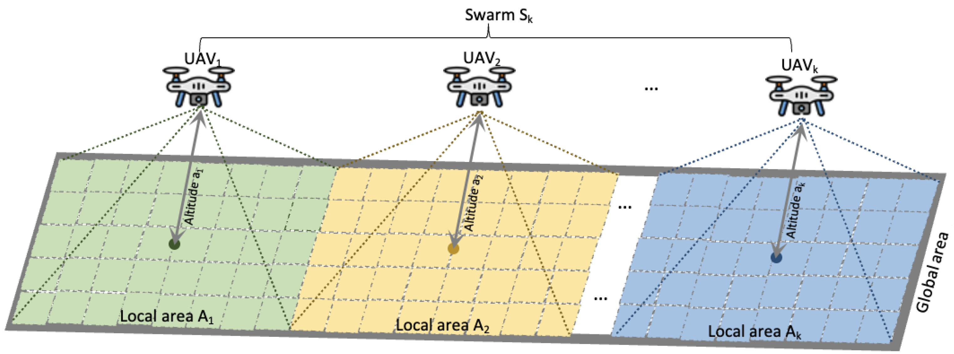
Scheduling a mission in a swarm is a scheduling problem that involves organizing the execution of Robot Operating System (ROS) (https://www.ros.org/ (accessed on 1 August 2024)) nodes in a parallel (multicore) and distributed (multi-UAVs) manner. As seen in Figure 1, adopting a multi-UAV system to enable collaboration missions entails three stages. The first stage concerns the assessment of the environment. It consists of partitioning the exploration environment into subregions. In accordance with the workload balancing constraint, each UAV is assigned to a subarea. This gives every UAV a local perception. Depending on the homogeneity of the swarm, the partitioning may be performed using the shape-based partition approach if the UAVs are homogeneous [76]. Shape-based partitioning splits exploration areas into preset shapes, like grids, cells, and regular or irregular geometric boundaries. Partitioning relies on the structure or geometry of the space itself, and the resulting divisions often adhere to rigid, often artificial borders. The well-known, common methods are grid partitioning, Voronoi partitioning, and geometric clustering [83,84]. In the opposite case, the density-based partition method is the most suitable [11]. Density-based partitioning divides exploration regions according to the density of waypoints, the types of UAVs involved, or the complexity of mission tasks. Rather than focusing on predefined geometric boundaries, this approach is tailored to identify dense subregions, concentrating on high-density zones and reducing partitions in sparse regions. Common methods such as DBSCAN, Mean Shift, and k-Means with Density-Based Refinement are suitable for this purpose [85,86]. Then, in the second stage, mission jobs are processed in priority order. Each job is executed in a distributed manner throughout the swarm depending on the number of core processes available per drone. The last stage concerns the coordination of the tasks running for the mission achievement. Synchronization of tasks is carried out via message-passing [87] and consensus definition [38], which, respectively, facilitate communication and control of swarm actions.
The topic covered in this work is a cooperative variant of a multiagent system (MAS), called Model-reflex agent [30], as shown in Figure 2. The agents in this MAS form a fleet of drones { UAV 1 , UAV 2 , ⋯, UAV k } composed of one leader and followers. The swarm is homogeneous if i , j 1 . . k , such as i j , and we have UAV i = UAV j . This means that the UAV i and UAV j share the same hardware and software properties and communication infrastructures [76]. Otherwise, it is considered heterogeneous if the UAVs of S k have different characteristics. The exploration environment defined as a set of waypoints covers a finite three-dimensional area A R 3 × N + such as A [11]. In addition, from a given altitude a i , each UAV i provides a sensing capability p i = { ( x i , y i ) } of its environment A i according to the perception function defined as p i : A i R 2 × N + , where A i A , | A i | 0 , 0 < a i z i .
The mission M to be planned in the swarm is defined as an ordered set of m jobs { j 1 , j 2 , , j m } such i j 1 . . m , j i j j . Depending on the field of application, the mission’s jobs are processed successively or simultaneously. For parallelism reasons, each job is chunked as a smaller and more manageable set of tasks { t i 1 , t i 2 , , t i k } , such as t i k being a unit process or thread of job j i that runs on the k t h drone. Let p N + be the number of core processors of each UAV. A given UAV i S k can perform a parallel execution of a set of different tasks { t 1 i , t 2 i , , t p i } , such as t k i t l i . Each UAV i interacts with the others via messages m i . Furthermore, every action performed has an impact on the drone’s state q i .
The complexity of the problem stems not only from the number of UAVs and their respective duties but also from the requirement for UAV collaboration [48]. The following are some intriguing complexity metrics for the problem assessment: (1) the number of core processors (parallelism complexity), (2) the time needed to accomplish the mission (time complexity), and (3) the amount of messages exchanges during the mission execution (communication complexity).

3.1.1. Stage 1: Area Partition

Initially, for a fixed number k of UAVs after the environment assessment, the first challenge consists of partitioning the exploration area A under k local areas A i A so that each UAV i S k is assigned to one local area A i . We consider that P k = { A 1 , A 2 , , A k } is a k-partition of the exploration space if [11]:
  • i 1 . . k , we have that A i 0 A i is a nonempty space.
  • i 1 . . k , we have that A i A j = A i and A j are disjoint two by two.
  • i = 1 k A i = A .
For k 2 , this problem becomes NP-Complete [88] since there is no polynomial-time method that allows one to have optimal results. In this work, we focus on the shape-based partition method [11] assuming that the UAVs are homogeneous, as shown in Figure 3. It consists of generating numerous local areas A i P k that are symmetrical in terms of size and weight so that A i , A j A , | A i | = | A j | . Thus, if | A i | > | A j | , this means that the i t h area is wider than the area A j . Consequently, the workload balancing will be unevenly distributed across the swarm S k , as UAV i will work more than UAV j . The partition P k must highlight the fundamental properties of workload balancing of the swarm S k . Let w i R + be the workload of the UAV i and w a v g be the average workload of the swarm, such as
k 2 , w a v g = i = 1 k w i k
Let ϵ be the acceptance of the deviation error of the partition of region A into a set of local areas A 1 , A 2 , , A k such that the workload w i of each UAV i does not exceed the average workload ( 1 + ϵ ) × w a v g , we use the DHPV algorithm proposed in [89]. The workload balancing w s of the swarm S k to perform the swarming mission depends on the partition P k . It is taken from [90] and is stated as:
w s = i = 1 k w i w a v g 1 2 k ] 0 , 1 ]
This workload is balanced if the constraint w s 1 + ϵ is met, which means that the workload w i of each UAV i S k is equitably correlated to the average workload w a v g [11].
Lemma (Dispersion of the workloads w i ) Given a k-partition S k of the exploration region A, the constraint of workload balancing w s is not respected if for all UAV j S k with respective workloads w j R + , there is a UAV i whose workload w i causes the imbalance of w s such as i , j 1 . . k , we have:
w i > w a v g k ( 1 + ϵ ) + k j = 1 , j i k w j
The coverage of a subarea A i depends on the targeted altitude a i R + of the UAV i . By flying at a higher altitude, the drone perceives a larger area in a single instance. This means a greater chance of gathering more information of the area but with a spatial sampling distance penalty. When switching to multiple UAVs, altitude a i variation impacts not only the UAV i ’s local perception p i , but also its workload and therefore the flight time of the swarm. In this work, to keep things simple, we assume that the UAVs fly at the same altitude, so that ∀ UAV i , UAV j S k such as i j , we have a i = a j .

3.1.2. Stage 2: Mission Planning

The second stage concerns the mission planning strategy for swarming. For high-performance computing involving distributed and parallel computation, mission jobs are distributed throughout the swarm S k and executed in parallel [48]. Figure 4 shows the computation model of the planning strategy M = { j 1 , j 2 , , j m } , it consists of three steps. First, the set of jobs { j 1 , j 2 , , j m } of the mission submitted by the operator is split into a set of ROS nodes [91] { t i j } such as j 1 . . k , i 1 . . m . Each node t i j j i assigned to a UAV j contributes to the achievement of its intermediate mission in its local region A j A . Then in the second step, the chunked jobs are sent to the follower UAVs having enough available resources (CPU, memory, and disk). Assuming we allocate one processor core per drone for each node, each follower UAV will be able to execute multiple ROS nodes to compute the mission tasks simultaneously and concurrently [91]. We consider O ( j l ) as the time needed to execute all mission’s jobs of the swarm. If we assume that the drones are homogeneous, the time spent by such a scheduled job j l to run across the swarm is equal to [11,90]:
O ( j l ) = max 1 i k { O ( t l i ) } i = 1 k O ( t l i ) k
We define O ( M ) as the time complexity of the mission M when a sufficiently number of processor cores p is available. It depends on the complexity of the tasks as well as the number of processor cores available on each UAV i S k and imposes certain precedence constraints on the priory order that these tasks are to be performed. To completely determine a swarming mission, we have to specify which processor core performs what task t l k of what job j l at what time. Let us assume that we have available a pool of p processors and each processor can perform any one of the desired jobs. For any job i ( i 1 . . m ) , let { c i 1 , , c i k } be, respectively, the small CPU of the drones { UAV 1 , UAV 2 , ⋯, UAV k } tasked with performing the corresponding operation. Also, we let t i be a positive integer variable specifying the time that the operation corresponding to job j i is completed. We initially assign no processor to any mission jobs, and we use the convention t i = 0 for every submitted job i. There are two constraints that must be imposed:
  • A core processor can perform at most one ROS node at a time. Thus, if i j , and t i t j , then t i k t j k for UAV k .
  • If t j > t i + 1 , this requirement reflects the fact that the node corresponding to job j j can only start after the node corresponding to job j i has been completed.
Once c i k , j i and t i have been fixed for UAV k , subject to the above constraints, the mission M can be scheduled for parallel operation across the entire swarm S k . So, we call the set { c i k , j i , t i } a schedule. The above-described setup could correspond to a variety of actual implementations. For example, a processor c i k could store the result x i of its task t i k in a shared memory from where it can be retrieved by other processors. Alternatively, in a message-passing implementation [87], processor c i k sends a message m i to any processor c j k that needs this value. In practice, memory access or the transmission of a message may require some time, and this has been neglected in our early discussion. If the transmission of a message requires exactly θ time units, then the constraint t j t i + 1 should be modified to [92]:
t j t i + 1 , if intra - process
and
t j t i + 1 + θ , if inter - process
In fact, even this requirement is rather crude because the message delay θ may depend on location of the processors in that interconnection network. In case that the processors c i k and c j k are inside the same UAV (intraprocess communication), the message delay is assumed to be negligible. Otherwise (inter-process communication), there is a delay θ . In the next stage, we address this aspect in detail.

3.1.3. Stage 3: Message Passing

The last stage concerns the setting up of the message-passing paradigm, in which UAVs communicate by publishing and subscribing to ROS messages over bus topics. Each topic provides a bidirectional communication between two UAVs [11,87].
More formally, the communication system is defined as a set of pairs { ( UAV i , m i ) } corresponding to the messages exchanged between the UAVs in the swarm. Each UAV i S k is theoretically modeled as a finite-state automaton with state q i . Each state of the UAV i allows two types of message access, publisher and subscriber [76]:
  • Publisher i [ m i ] : holds message m i that UAV i has sent to the other { UAV j | j i }.
  • Subscriber i [ m 1 , , m k ] : holds messages { m 1 , , m k } that have been received by UAV i .
The behavior of the swarm over time depends on the specific type of system being modeled. We classify this behavior as either publisher ( q i = p ) , subscriber ( q i = s ) and wait ( q i = w ) , as shown in Figure 5. The publisher state is an instance in which the UAV i can only send a message m i , unlike the subscriber state, where it only receives messages. In some cases, the UAV switches between the two states to send and receive messages at the same time. The last state q = w is when the UAV i is waiting. This waiting time depends on the time delay θ defined by the operator. During this delay, the UAV i can neither send nor receive a message.
The message-passing technique for invoking the behavior of the drones during communication with no failures depends on the time models: synchronous or asynchronous [87]. In the synchronous model, UAVs execute tasks in lockstep. The communication is partitioned into rounds, and in each round, each UAV i S k can publish its message m i and subscribe to messages { m 1 , , m k } published by the other ( k 1 ) UAVs of the swarm. On the other hand, the asynchronous model is a communication model based on both the time delay t i and the transition state q i of the UAV i . During the time delay θ , UAV i will oversee communication depending on its transition state:
  • q i = p , i j , q j = s for all UAV j S k { UAV i } . This means that UAV i publishes messages m i throughout the swarm.
  • q i = s , UAV j S k { UAV i } such as q j = p . This means that UAV i subscribes to the published messages m j of the UAV j .
  • q i = w , t i R + , q i s and q i p . This means that UAV i is on standby.

3.2. System Architecture

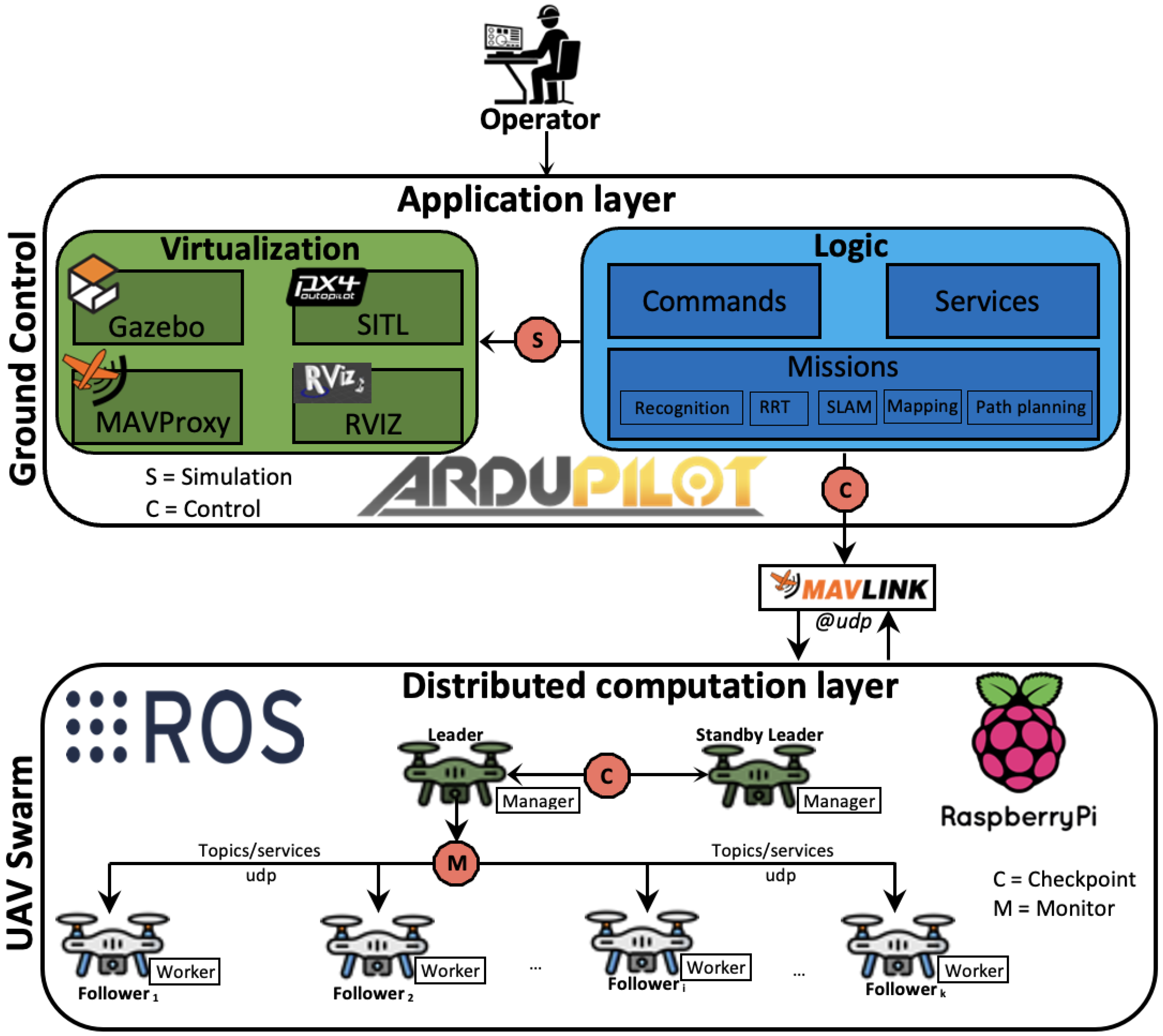
In this subsection, we present the architecture and design operation of the proposed multi-UAV system. Figure 6 depicts the architecture’s components. It is multilayers and based on both ardupilot (https://ardupilot.org/ardupilot/index.html (accessed on 3 October 2024)) and ROS framework [91] as they are open source and established as industry standards. It is a trustworthy, flexible, and portable system that can control several types of aerial vehicles: single-rotor, helicopters, multirotor, fixed-wing aircraft, and VTOL airplanes [11]. The design of the architecture relies on two main layers: application and computation layers. They are fully connected so that the output of the previous application layer is the input of the computation layer. Moreover, the interactions within the multi-UAV system are based on the MAVLink protocol (https://mavlink.io/en/ (accessed on 20 September 2024)), which guarantees interoperability with different types of UAVs and between onboard drone components.

3.2.1. Application Tier

The application tier is a well-established layer that organizes mission planning and swarm control of the system into two independent components: virtualization and logic. The virtualization tier is also known as the simulation component for preflight mission planning without physical infrastructure. It is built on top-level of open-source software such as MAVProxy (https://ardupilot.org/mavproxy/ (accessed on 20 September 2024)), Gazebo (https://gazebosim.org/home (accessed on 22 June 2024)), SITL (https://ardupilot.org/dev/docs/sitl-simulator-software-in-the-loop.html (accessed on 5 October 2024)), and RViz (http://wiki.ros.org/rviz (accessed on 6 May 2023)). MAVProxy is a lightweight ground station software that controls the UAVs through a powerful command-line architecture. It provides real-time telemetry data and manages the performance metrics of the UAVs. It is a conventional ground control station, similar to QGroundControl (http://qgroundcontrol.com/ (accessed on 2 October 2024)) or MissionPlanner (https://ardupilot.org/planner/ (accessed on 3 October 2024)), allowing to accomplish simple tasks like launch missions, monitor telemetry data, drone performance metrics, control flight modes, and gather flight logs. The Software In The Loop (SITL) simulator combined with Gazebo enables autopilot capability to simulate autonomous flights in a realistic world without any hardware (rotors, sensors, copters, and so on). It is built on top of C++ APIs allowing one to compile and launch executable robust and complex flight programs without hardware dependency. In contrast to Gazebo, which depicts the simulated world’s realism, Rviz shows the perception that UAVs have of their environment, whether real or virtual.
The logic tier or abstraction layer is the heart of the multi-UAV system. It allows one to call and implement the control commands, consensus, and rules associated with each of the tasks assigned to the swarm UAVs by concealing the implementation details. Since the programming paradigm of the UAVs is based on the ROS framework, it provides an API that supports higher-level functionality in both C+++ (roscpp) and python (rospy) libraries [91]. It is designed so that the built program can run both on virtual as well as real swarms. Eventually, the swarm communication is abstracted by the mavros [93] package that enables MAVLink extendable communication from one to many UAVs running ROS nodes. Commands and services provide application programming interfaces that enable two or more nodes to communicate with each other. They contain all the specifications required to call commands and services for the high parallelism of ROS nodes running on all the drones in the swarm. The mission component is dedicated to complex missions such as massive object detection, large unknown space exploration, and mapping activities [11,76].

3.2.2. Computation Layer

The computation layer is responsible for distributing the missions across the swarm regardless of the Leader–Followers paradigm [46]. The computation layer of the swarm is decentralized and involves two types of UAVs which establishes a dyadic relationship between leader UAVs and follower UAVs. It evolves over time in three phases: role assignment, role affectation, and role routing [94]. Role assignment is the initial phase in which the leader UAV assigns roles to followers UAV i S k and assesses their states from feedback controls. Because leader UAVs are unfamiliar with followers in the initial phases of the interaction, they may appraise their availability based on their current states and the consensus error from the goal state [40]. Convergences toward the goal state will increase mutual attraction and trust between leader and follower drones, leading to a decrease in consensus error [40]. In the role affectation phase, leaders assign roles to followers if they consider those UAVs to be in good condition and satisfy mission expectations. Simultaneously, follower UAVs will wait until they satisfy current roles before the acceptance of new role assignments. Finally, in the role routing phase, the relationship between leader UAVs and follower UAVs improves iteratively over time as they converge to a common state [46].
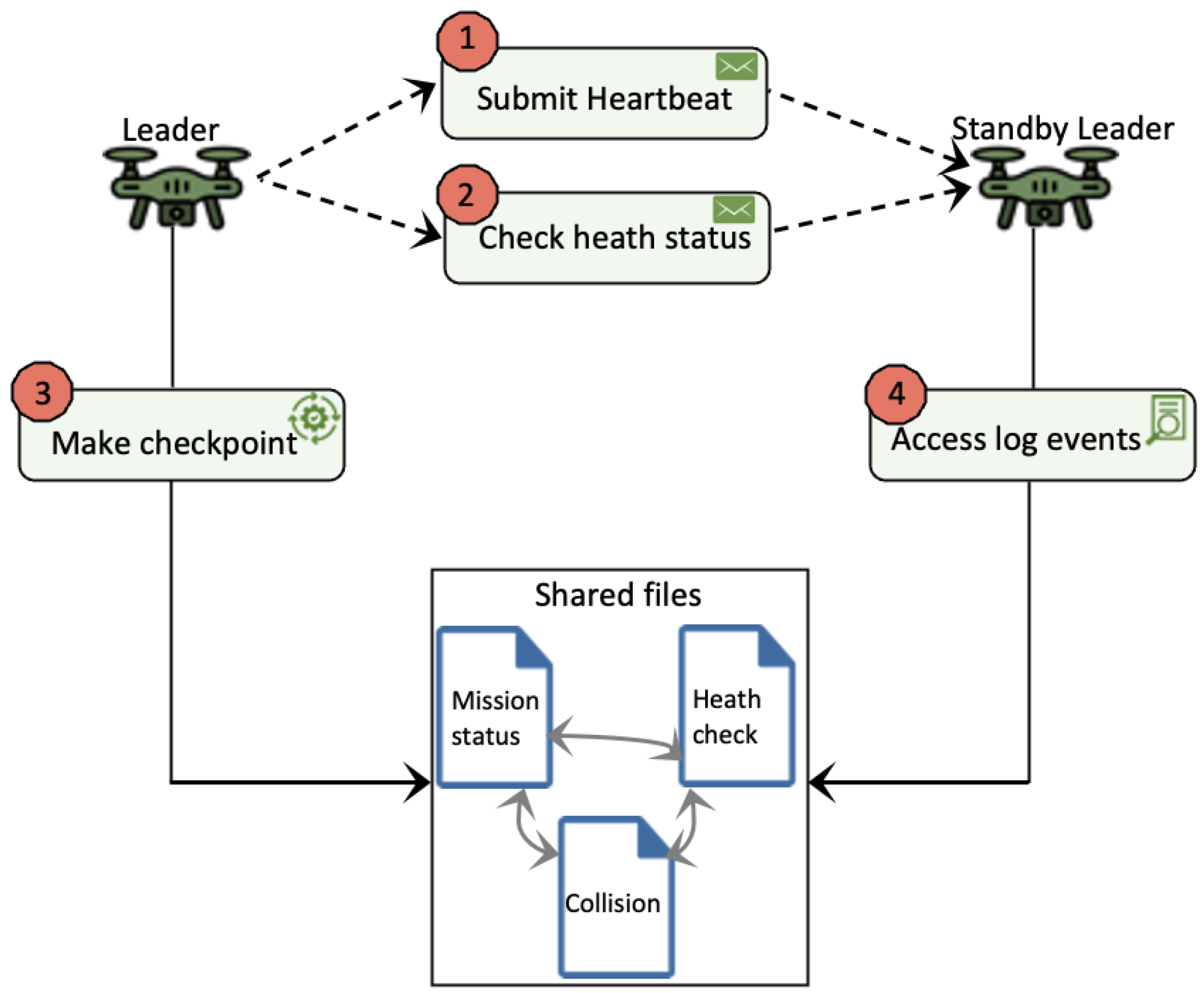
The communication between the application layer and the swarm is achieved through the leader UAV. The swarm is fully connected and uses UDP-based protocols for inter-UAV communications. It also receives the list of mission jobs and shares it with all the follower UAVs according to the swarm topology (ring, star, or meshed) [11]. Furthermore, the leader UAV serves as a gateway to relay the information between the GCS and the rest of the swarm. It is also responsible for swarm control and monitoring mission jobs throughout the swarm. When the operator submits a job, the leader UAV first requests for list of available processor cores on each follower UAV. Then, it sends the jobs as a task to be executed to the available drones. For fault tolerance, a secondary leader UAV also called “Standby Leader” provides fail-safe capabilities in case of leader UAV failure. It performs regular health checks on the leader and ensures mission continuity in case of problems. Leader UAV continuously sends a heartbeat to notify its availability, followed by a set of health status information. If, after a while, the standby leader UAV receives no information from the leader UAV, it automatically switches from standby to active state. This state occurs when the standby leader detects a negative event from the leader UAV. This may be due to a crash or hardware and software malfunctions.
On the other hand, the follower UAVs simultaneously execute the tasks assigned by the leader and periodically report back mission status. It is important to note that the total time to complete all mission jobs M = { j 1 , j 2 , , j m } depends on the number of drones k and processors p. When one UAV j finishes running its task t i j j i , it waits for the other drones to finish their tasks. This principle allows one to reduce the time complexity of the mission M by the number ( k 1 ) of follower UAVs.
The mission M to be performed with swarm S k is fully distributed and satisfied if the following hold [11]:
  • j 1 . . k , i 1 . . m , O ( t i j ) 0 , and all ROS nodes run.
  • For a given UAV j , the running nodes t i j , t l j are different two by two, t i j t l j = .
  • Once all the nodes t i j have been completed, we obtain i = 1 m j = 1 k t i j = M .
For good parallelism, the right number of ROS nodes n required to complete a mission job is calculated as follows [76,95]:
n = 0.95 × k × p , if homogeneous swarm 1.75 × k × p , if heterogeneous swarm
With 0.95, we assume that the swarm is homogeneous, this means that UAVs share the same hardware components (rotors, captors, batteries, and so on) and computational capabilities (RAM, Chipset, and CPU). While with 1.75, the swarm consists of different kinds of UAVs. The most efficient drones carry out a greater number of tasks and launch a new wave of tasks immediately when they have finished. Messages and services shared across the swarm are managed by ROS topics and services. During the computation, the topics are asynchronously published and subscribed by the UAVs allowing them to synchronize the called ROS services as client or server [91].

3.2.3. Service Thread Pool

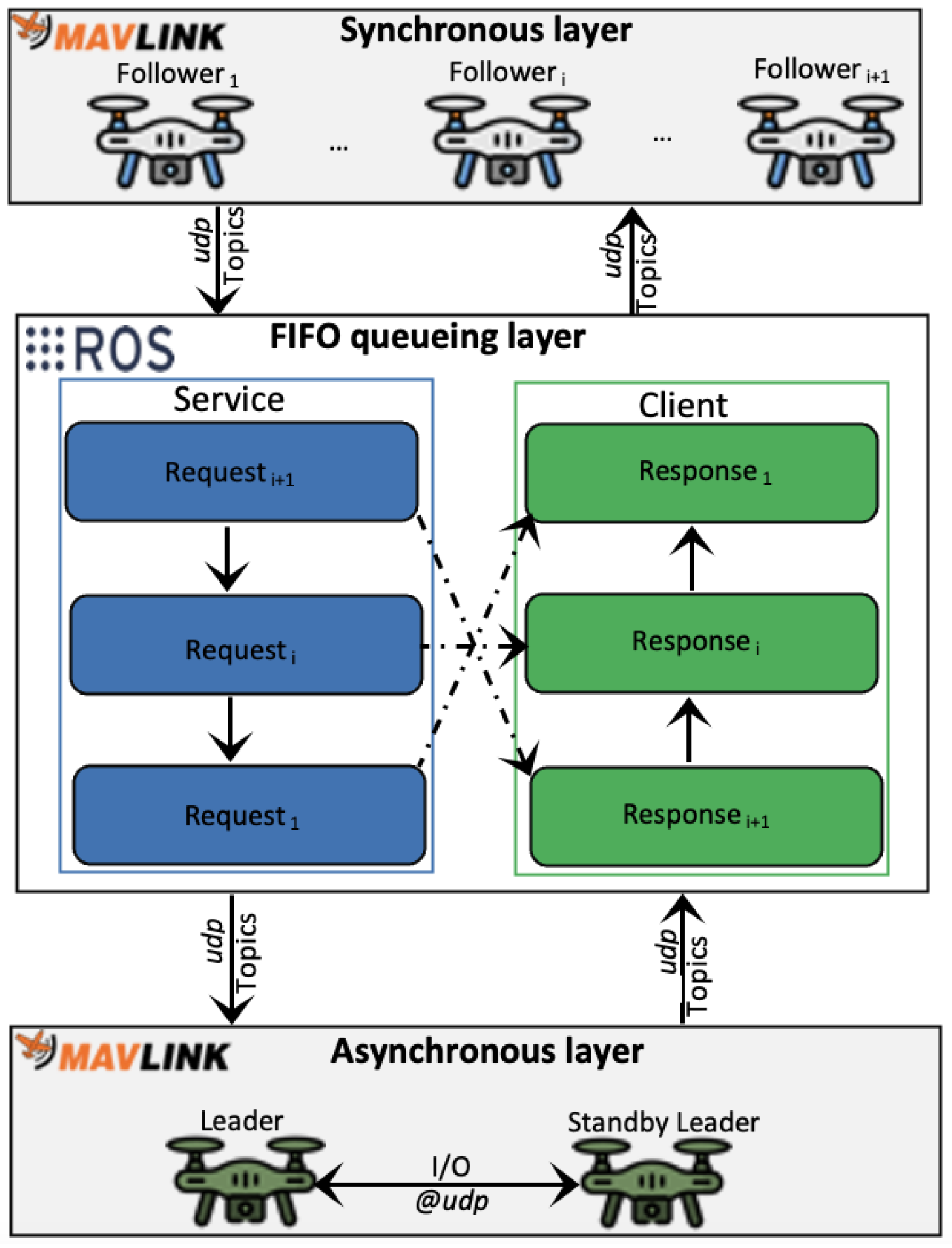
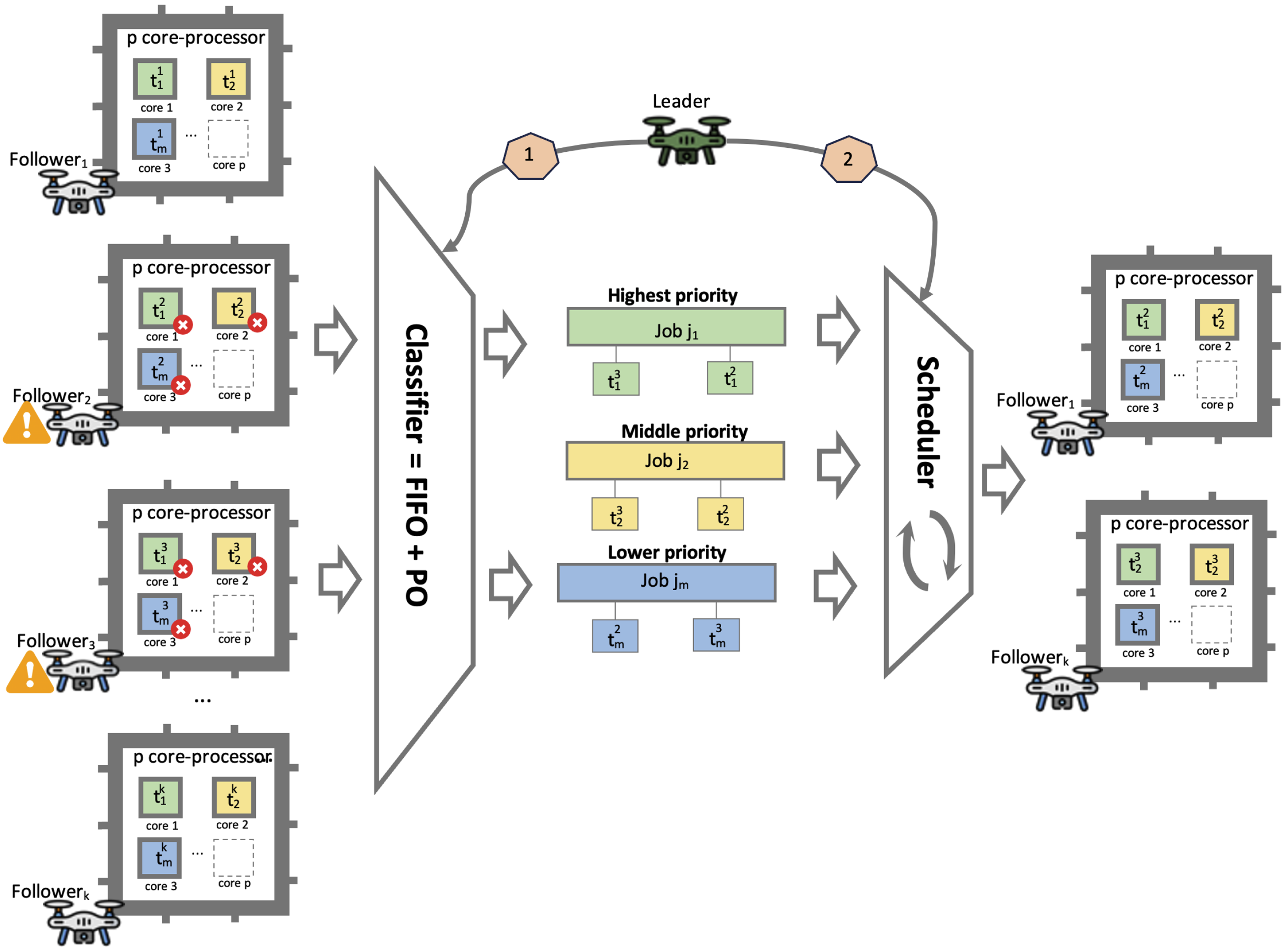
Collaborative mission achievement in a swarm involves numerous synchronous follower-to-follower and asynchronous leader-to-follower services as shown in Figure 7. Access to the service is based on the first in–first out (FIFO) queuing mechanism [96], and each UAV accesses them via ROS (https://www.ros.org/ (accessed on 1 August 2024)) topic buses that transfer data between components inside a drone or between drones [91]. Their handling is tricky because the services run in a distributed, parallel, and concurrent manner. In this context, a thread pool is a good fit for service access management. A service thread pool is a collection of threads available that operate a queue of services. It is used to boost speed when executing a wide range of synchronous and asynchronous services by lowering the invocation load per task and providing a mechanism of bounding and controlling the resources used when running a set of tasks [97,98]. To serve a single request, two threads are utilized by default: one for processing the request (service) and one for getting the response (client). When a service is called by a UAV, if it does not exist in the thread pool, then an instance of this service is created. Otherwise, it uses an instance of the available service for request/response.
The first UAV i to call for service is the first to be processed. The next UAV i + 1 waits until the first finishes and so on. If the number of services is greater than or equal to the capacity of the thread, the idle services are automatically stopped and removed from the thread pool. This enables to free up CPU and RAM resources for running other services in the queue. It is also important to mention that the maximum number of s i j services running by UAV i cannot be greater than its maximum number of core p. So, the total number s of services that can run simultaneously in the swarm S k is calculated as follows:
s = i = 1 k j = 1 p s i j p × k

3.2.4. Communication Scheme

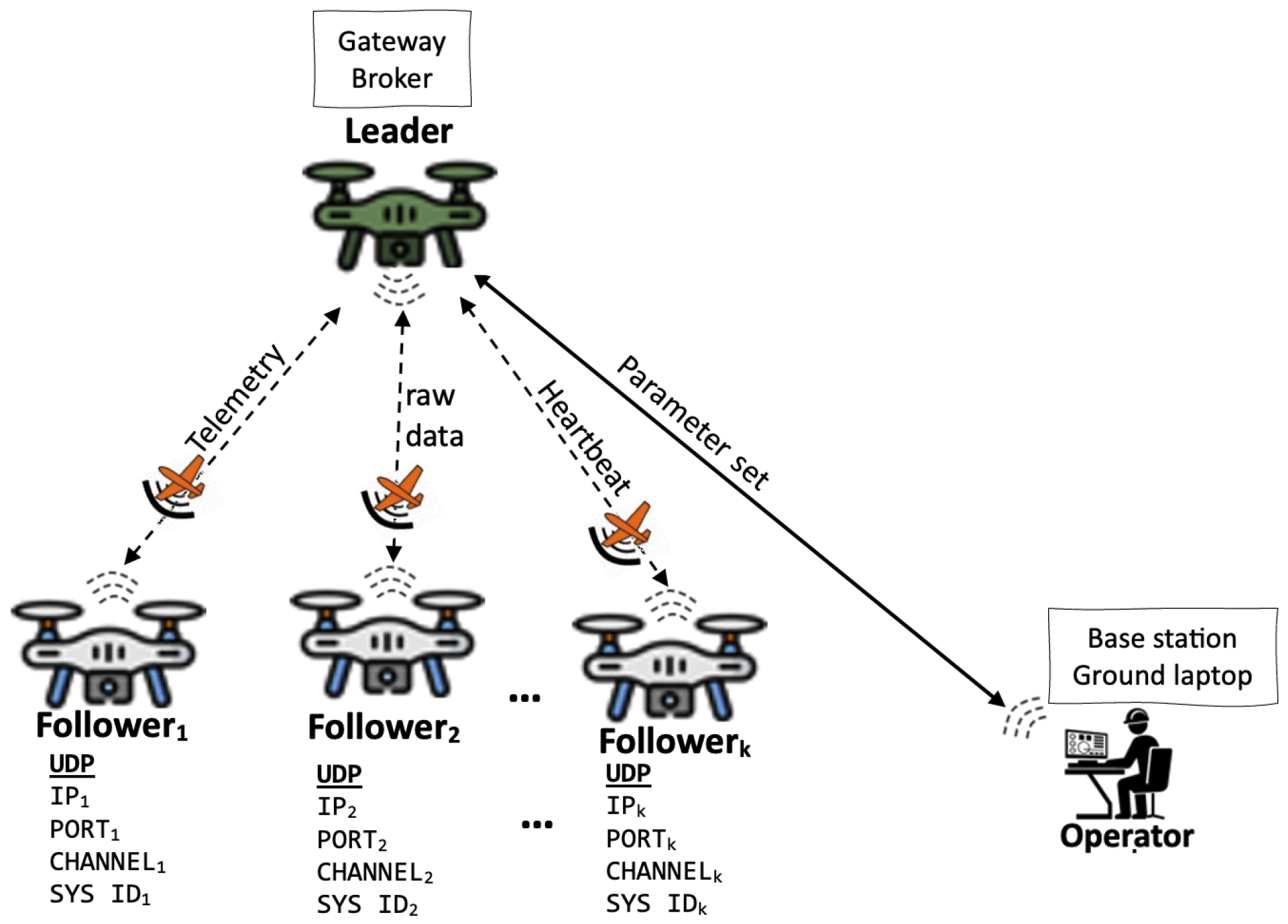
The communication design of the swarm is based on a single-group architecture. It is a decentralized scheme that fosters drone-to-drone communication, hence removing reliance on the GCS [11], as shown in Figure 8. The GCS communicates with the swarm via the leader drone, which acts as a “Gateway UAV”. It supervises and relays data between the GCS and all UAVs using MAVLINK protocol. Each follower UAV in the ad hoc network is equipped with a wireless point-to-point communication device allowing them to operate as a single access point. Meanwhile, the leader on-board communication module provides a point-to-multipoint link to the followers and the GCS. To maintain the swarm’s scalability, we use the ring topology, which means that all bidirectional interactions between two UAVs must take place via the leader drone. Since the communication infrastructure is supported by MAVLink protocol, the swarm is scalable up to 255 UAVs or sensors [93].
A UAV is integrated into the swarm’s wireless network via a bridge communication utilizing a UDP/Wi-Fi connection. When the connection is established, an end-to-end path is created in the routing table. This routing table serves as data transmission rules for each drone. The same process is repeated until k drones of the swarm are integrated. To ensure optimal message broadcasting and avoid packet collisions, each drone is recognized across the wireless network using unique identifiers, which ensures that each UAV is distinct:
  • SYS ID: System identifier assigned to each drone. Its value varies from 1 to 255.
  • IP: The IP address used to identify the drone on the wireless network.
  • PORT: The listening port used by the GCS and drones to send/receive packets and commands.
  • CHANNEL: Communication channel used by the GCS to transmit telemetry data to the fly control unit of each drone.
  • BAUDRATE: Speed at which each drone transmits and receives data.
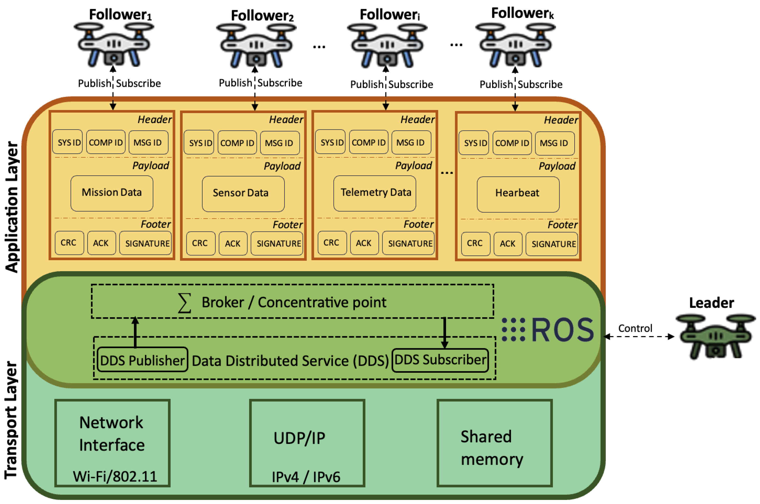
As shown in Figure 9, communication within the swarm is based on MAVLink message-oriented protocols, where messages are sent with a built-in priority order on different topics or channels. They occur in the (1) application layer, which defines the structure of messages exchanged throughout the swarm, and (2) transport layer, which ensures reliable message routing. Each message is encoded in a packet structure that guarantees transport-level reliability. Message structures consist of a header, payload, and footer. The header holds identity and verification information, the payload stores the data itself, and the footer contains information about the integrity and security of the message. Payload semantics depend on message types (control messages or data messages), which are highly context-dependent:
  • Heartbeat signal is a periodic message sent at a lower frequency by each drone to indicate that it is alive and operating normally.
  • Telemetry data provide feedback (waypoints, altitude, position, roll/pitch/yaw, speed, IMU, and diagnostics) concerning the drone’s mobility.
  • Mission control messages contain instructions (such as take-off, landing, set mode, rtl, etc.) used to send mission control commands with higher priority and frequency.
  • Sensor information contains raw data from onboard sensors (e.g., GPS, GNSS) or cameras (e.g., thermal, spectral, or hyperspectral camera).
  • Parameter set contains standard definitions (e.g., HEARTBEAT, SYS STATUS, or PARAM VALUE) used for the management of the multi-UAV system.
Each UAV uses a separate channel to broadcast these messages concurrently over the same communication link. To distinguish itself in multi-UAV scenarios, each drone uses its own SYS ID and COMPONENT ID. All messages are concentrated and controlled on the leader UAV, which acts as a broker or concentrative point, and data separation is not achieved by physical channels but through message IDs and types.

3.3. Self-Organization

3.3.1. Consensus Control and Policy

Policy control, often known as policy management, is a technology that allows to define and apply operational rules and security regulations in the swarm intelligence [38,39,40]. It is static and local for each UAV and depends on its function (leader or follower). As shown in Figure 10, the swarm control policy consists of three main control services: SwarmManager, Standby SwarmManager, and DroneManager. The three ROS services communicate via an asynchronous message-passing interface in which the publisher can send a topic without waiting for the subscriber to be ready. The topic is buffered and retrieved by the subscriber as soon as it is available. This nonblocking communication approach provides greater flexibility, which is required for large-scale swarm management. It is also adapted to support GCS-to-leader and leader-to-follower communications.
The SwarmManager is located on the leader UAV, and it consists of MissionPlanner and MissionManager components. It receives the missions submitted from the ground control station by the operator and processes them using the MissionPlanner component. On this basis, the leader decides the way missions are prioritized and how followers are allocated to the missions using FIFO scheduling policies [96]. After that, the MissionManager talks to the DroneManager(s) located on the follower UAVs via a message-passing interface (MPI) [87]. Based on the negotiations made with the DroneManagers of the swarm, SwarmManager successfully finds a follower UAV having enough resources (processor, RAM, power, sensors, autonomy, etc.) to create a ROSContainer, and then launches the ROS nodes, respectively, for a set of tasks. The number of ROS nodes running concurrently in the container is defined by the operator and cannot exceed the number of core-CPUs per drone. By default, two nodes are instantiated: the first instance for the autopilot and the second for the swarm control policy. In the meantime, the TaskManager monitors locally the nodes running in that follower UAV. Once all ROS nodes finish running, the TaskManager notifies the end of the mission to the SwarmManager.
The SwarmManager is the heart of the multi-UAV system, and it manages the swarm as well as being responsible for resource allocation. When it receives a job request from the operator, it splits tasks and forwards them to the appropriate followers, on which the actual execution occurs. It optimizes the swarm utilization (e.g., keeping all drones active) while considering different constraints such as autonomy, flying mode, maximum altitude, payload capability, etc. It is made up of two components: MissionPlanner and MissionManager.
  • MissionPlanner autonomously manages the assignment of the mission tasks on the whole swarm. The tasks are assigned to only active UAVs within the limitations of resource capacities, queues, and so on. It is referred to as a pure mission planner, which means that it does not track the status of the mission. Upon mission or UAV failures, the MissionPlanner reschedules the failed tasks to other active UAVs.
  • MissionManager is responsible for monitoring and tracking the status of the missions running in the swarm. It continuously receives information about the status of the drones and the mission in progress. It handles the execution of the TaskManagers in the swarm and commands the DroneManagers to restart the ROS nodes in case of failure.
The DroneManager is located on the follower UAVs, and it is responsible for monitoring the ROS node utilization and reporting to the SwarmManager. The health of the follower UAV on which the tasks are running is tracked by the DroneManager. If it receives an instruction from the SwarmManager, it may also stop or shut down the ROS nodes. It consists of two components: TaskMaster and ROSContainer.
  • TaskMaster is the component that negotiates the allocation of resource usage (CPU, memory, and disk) for executing the tasks on the ROS nodes. Its main role is to coordinate the execution of the mission tasks and handle faults. It reports the status and progress of the running tasks to the SwarmManager. Once launched, it transmits frequent heartbeats, as well as the diagnosis of onboard sensors to the SwarmManager to assert its health status.
  • ROSContainer is a collection of ROS nodes used to perform the computation of the tasks. For each ROS node, hardware CPU, ram, and disk resources are allocated to the follower UAV for the running of the assigned task.

3.3.2. Fault Tolerance and Failover

Since the communication architecture of the swarm is based on a single-group architecture [1,11,15,37], it would not allow to ensure a fault-tolerance. Therefore, the high availability of the swarm relies on the SwarmManager. In case of failure or crash, the whole multi-UAV system would stop. In this context, we introduce the Standby SwarmManager hosted in a separate leader UAV to remove the problem of a single point of swarm failure. If the SwarmManager fails, the Standby SwarmManager takes over automatically. Figure 11 shows the state transition diagram of the Standby SwarmManager. Initially, it issues diagnostic requests on the status of the batteries, rotors, and heartbeats of the active leader UAV. If it detects any anomaly, it automatically switches to an active state and notifies the follower UAVs that it has taken control of the swarm.
During the execution cycle of the mission (see Figure 12), the active leader regularly sends heartbeats to the standby leader as well as his health diagnosis. At the same time, it performs regular checks on the state of the swarm and the missions being executed. This information is stored in a shared file accessible to the standby leader which can use it for the continuity of activities in case of failure of the active leader.
During the execution of the jobs by the UAV followers, it is possible that in some situations the execution fails due to computational capacity problems. In this case, the remaining jobs are reassigned to the available follower UAVs that have completed their tasks. This reassignment is performed in a way that respects the workload balancing constraint (Equation (3)) of the swarm so that each follower UAV i has almost the same workload w i as the others.
Figure 13 depicts the process of rescheduling failed tasks. The tasks are first classified according to queuing priority and then reassigned according to the FIFO principle [96]. The first failed task is reassigned to the first available follower UAV and so on. We have three types of operator-defined priorities: (1) highest priorities, which are the tasks coming from the required jobs and on which the other jobs depend; (2) middle priorities, which are complementary jobs that support the highest priority tasks such as exploratory tasks, monitoring, etc.; and finally, (3) lower priorities, which are optional jobs. According to the classification made, the SwarmManager chooses the available follower UAVs and assigns the tasks according to the FIFO principle [96].

4. Experimental Results and Validation

We assessed the performance of our multi-UAV system in this section. Reliability tests were carried out on a real swarm composed of two homogeneous quadrotors based on pixhawk/ardupilot architecture. Each drone is equipped with a Raspberry PI 2-based ARM Cortex-A7 architecture operating on 1 GB of RAM and 4-core CPU running at 900 MHz with a soldered 802.11 bgn wireless 2.4 GHz radio frequency, allowing a short-range communication of 250 m, as illustrated in Figure 14a. Our two drones typically use 4200 mAh (4.2 Ah) in a 3-cell configuration, each with a voltage of 3.6 V. The voltage when the battery is full is 12.6 V and when it is empty is 9 V, which gives a total average of 12 V × 4.2 Ah for a maximum flight time of 18 min per drone. The navigation module used is based on an M10Q micro-GPS with a compass equipped with an arm-based flight controller.
On the other hand, simulations were carried out in Gazebo 11 with a virtual swarm comprising six IRIS quadcopters configured in a homogeneous manner, including one leader, one standby leader, and four follower UAVs, as shown in Figure 14b. Each UAV is equipped with 2 × 12.59 V × 3.1 Ah batteries. We used QGroundControl 3.2 with MAVLink 2.0 for the full flight control of the swarm from the ground station. Each drone flies at an altitude of 5 m with a speed of 1 m/s and a local perception of 2 m 2 . We also set the local navigation tolerance at 10%. The implemented program is based on the ROS distributions versioned to the latest Noetic and Humble Hawksbill running on Linux Ubuntu 20.04 for workspace. The experimental results discussed in this paper concern coverage area A, number of drones k, flight time O ( M ) , power consumption, and latency θ (See Appendix B).

4.1. Proof of Concept: Rapid Coverage Mission

To highlight the effectiveness and reliability and validate our proof of concept, we carried out simulation tests with the Localization with a Mobile Anchor node based on Trilateration (LMAT) coverage mission [99]. It has been used to cover areas of interest ranging from 400 m 2 to 3.2 km 2 . In terms of complexity, the LMAT algorithm consumes quite a lot of energy due to the frequent acceleration and deceleration maneuvers during UAV navigation. In addition, for a large exploration area, the flying time jumps to an exponential complexity with respect to the size [100].
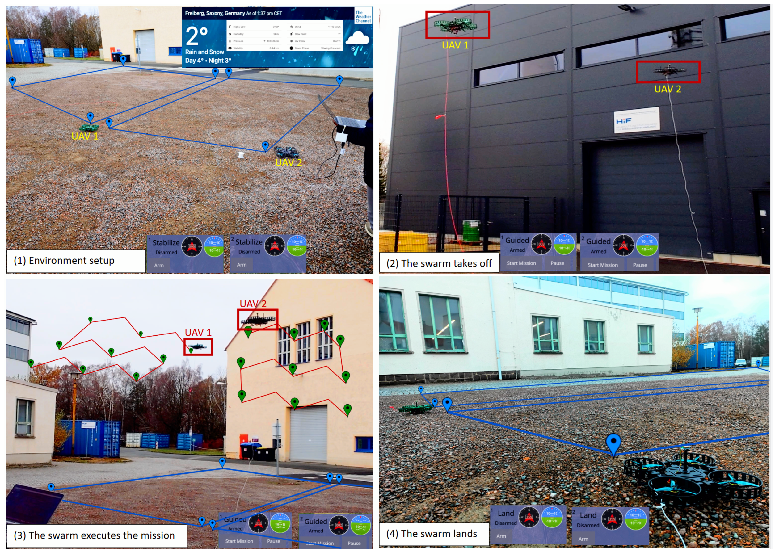
Figure 15 validates the proof of concept during a coverage mission in an outdoor test. It demonstrates the operational aspects of the swarm, from environmental assessment to overall area coverage. The mission tasks consist of three ROS nodes, each assigned to a single-core CPU. Two higher-priority nodes are used, respectively, for the execution of the LMAT coverage path and the messaging/swarm control policy, whereas the third, middle-priority task is used for collision avoidance (https://wiki.ros.org/teb_local_planner/Tutorials/Obstacle%20Avoidance%20and%20Robot%20Footprint%20Model (accessed on 5 July 2024)). During the operation, the black and green UAVs operate simultaneously as workers. Each UAV takes off, carries out its mission in its assigned area, and lands when its local coverage is complete. Compared with the current state of the art, ours is more convincing and validated from simulation to reality.
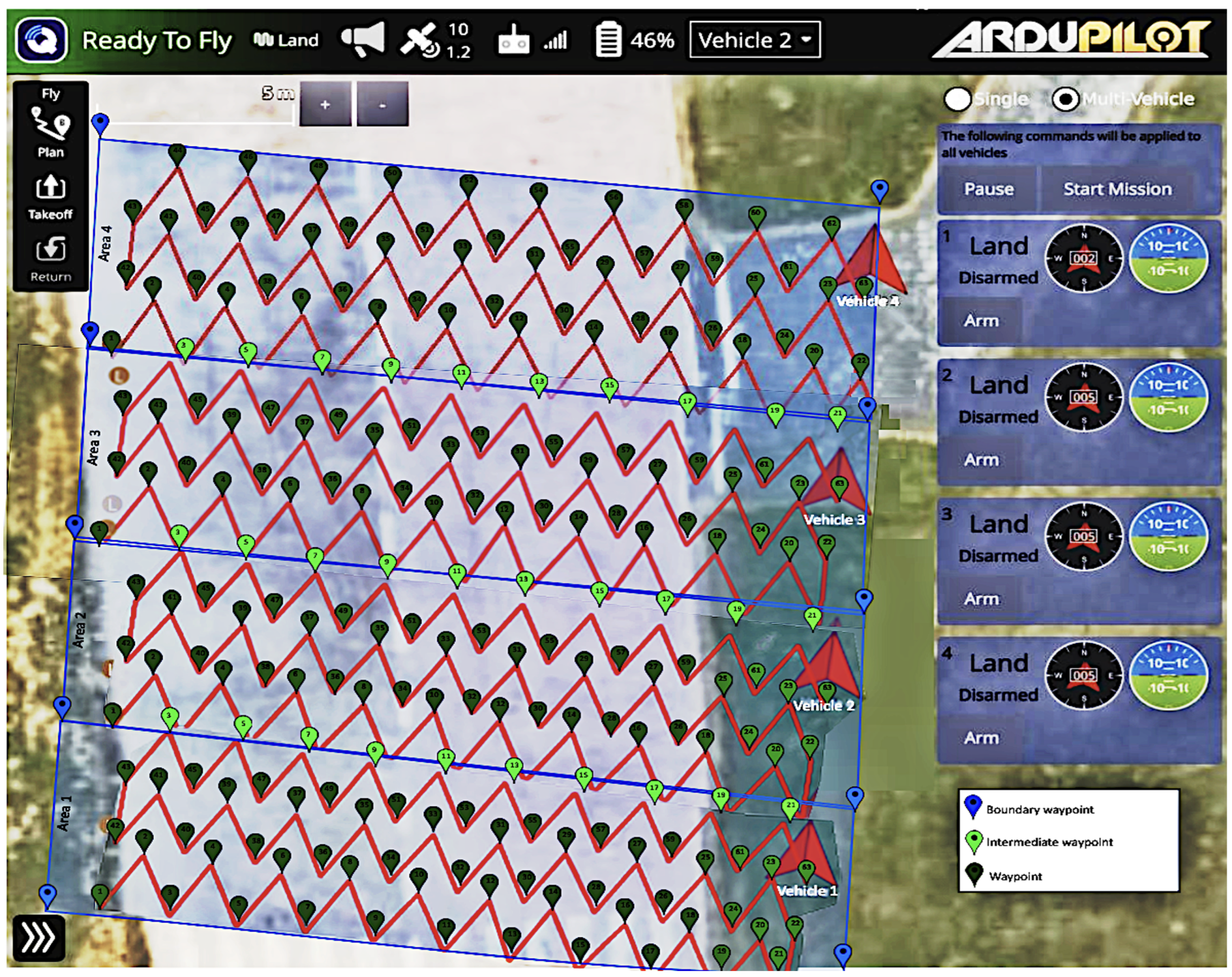
Figure 16 shows the coverage mission using the 4-UAV swarm. The coverage zone is divided into four subregions. Each subregion size is approximately equal to 100 m 2 and is assigned to one UAV of the swarm. Each subregion is bounded by a series of frontier points so that two adjacent UAVs share their intermediate waypoints. Blue markers are the points that delimit the area shape. While green map markers represent the waypoints to visit. Red straight lines are the intermediate paths to cover the whole environment. From its point of origin (the take-off point), each UAV flies towards these waypoints until it covers it local region. The coverage mission is carried out in a distributed way across the 4-UAV swarm. We obtained four intermediate coverage paths, each of which represents a partial path. Then, the complete coverage is obtained by merging the partial paths of the UAVs in such a way that the ending waypoint (landing point) of the UAV i becomes the starting waypoint (take-off point) of the UAV i + 1 and so on until the concatenation of the last intermediate coverage path.

4.2. Flight Time vs. Number of UAVs

The first topic of interest concerns the analysis of the impact of the number k of UAVs on flight time. We conducted experiments on spaces ranging from small to large dimensions and by varying the swarm from 1 to 4 follower UAVs. Figure 17 highlights how increasing the number of follower UAVs affects the flying time. We observed that as the swarm is extended from 1 to 4 follower UAVs, the flight time is considerably improved. Up until the linearity time is attained, the scalability of the swarm reduces the exponential time complexity to linear time. For an area of 3.2 km 2 , the coverage time decreases from 2 h 36 min (156 min) to 1 h 32 min (92 min) with a 2-UAV swarm, a saving of 1 h 04 min. This time is further improved from 32 min to 22 min with, respectively, three- and four-UAV swarms.
We also note that for small areas (400 and 800 m 2 ), adding more than two UAVs does not speed up the flying time. This means that the tasks performed by UAV 3 and UAV 4 can be assigned to those of UAV 1 and UAV 2 , respectively, for an almost identical coverage time. This led us to deduce that the swarming concept is dedicated to large exploration areas.

4.3. Energy Consumption vs. Number of UAVs

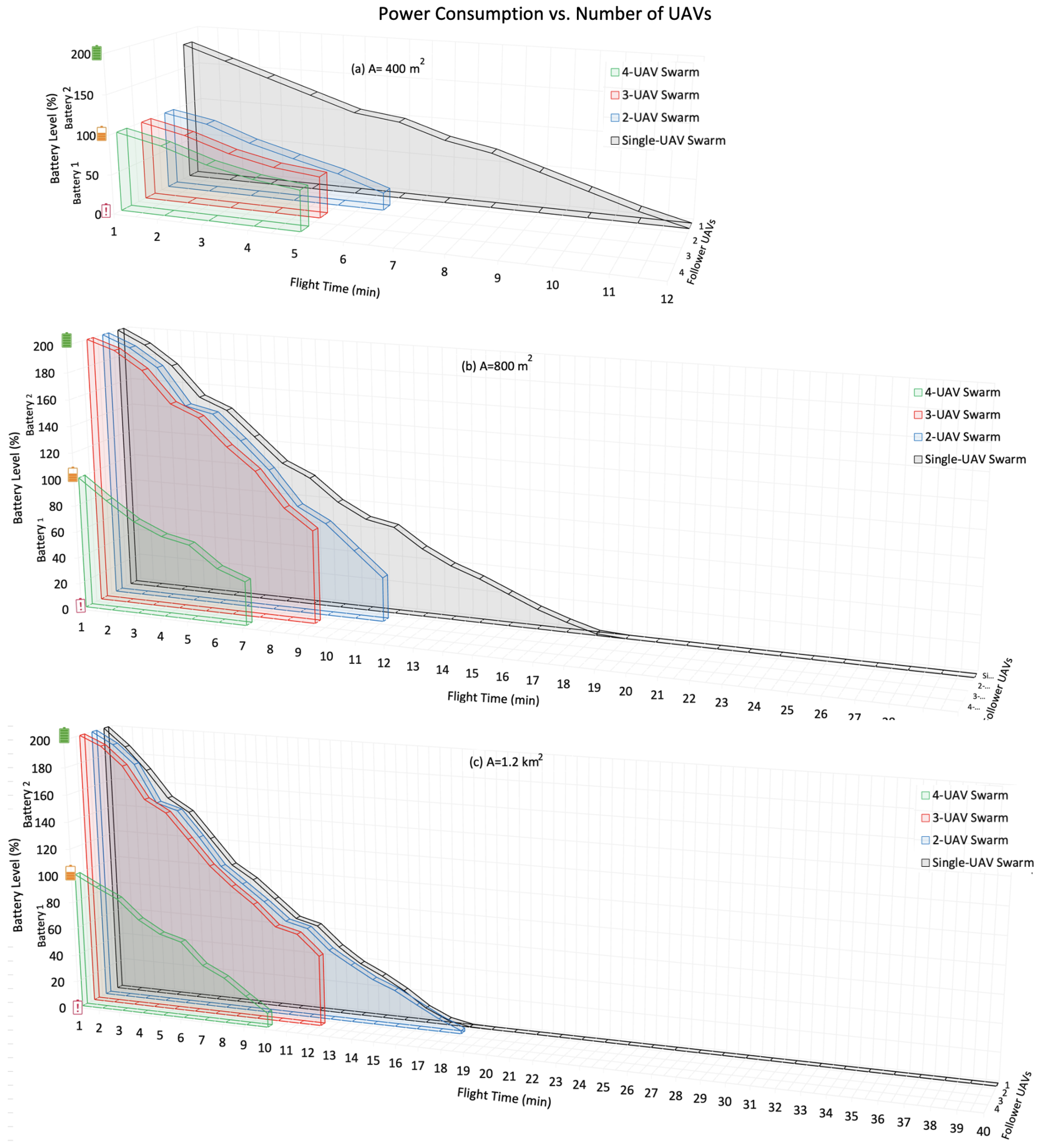
The second topic of interest is the average power consumption of each UAVs. Figure 18 depicts the result of energy consumption per follower UAV relative to swarm scalability. Firstly, we note that the swarming approach considerably reduces the average energy expended by UAVs to achieve coverage missions.
For an area of 400 m 2 , with the conventional approach, the full 200% (62 A) battery level is consumed for the mission. However, with the swarming concept, each UAV uses one battery and consumes an average of 78%, 49%, and 48% energy, respectively, for a swarm of two, three, and four follower UAVs. This represents energy savings of 22% (2.77 V), 51% (6.43 V), and 52% (6.55 V), respectively. On the other hand, for large areas (as shown in Figure 18a,b, the results are remarkable. With the conventional approach (single-UAV), the 200% energy is completely used up without the missions being completed. Our approach, on the other hand, makes optimum use of energy, enabling long-distance flights.
For example, for a 1.2 km 2 coverage (Figure 18a) with a two-UAV swarm, the coverage mission is barely completed by exhausting the entire 200% energy charge available in the two batteries of each follower UAV. With a three-UAV swarm, each UAV uses on average 2 / 3 of its energy consumption (140%) to complete the mission simultaneously. When the swarm is increased to four-UAV, energy optimization improves considerably. Each UAV uses almost half (90%, i.e., 11.34 V of 200%, i.e., 25.2 V) of its energy capacity. This represents an energy gain of 110% (13.85 V) per UAV.
The proposed approach shows good performance in terms of energy consumption over large areas. Unlike the conventional approach, it avoids downtime for recharging or replacing batteries, which has a major impact on mission duration.

4.4. Network Bandwidth and Latency

The third topic of interest concerns the network bandwidth and latency. Figure 19 shows the network packets per UAV transferred over the swarm. The first thing we remark is that the increasing number of follower UAVs reduces the published and subscribed packets of each UAV. This significantly reduces network bandwidth consumption and avoids network bottlenecks. If the communication architecture is decentralized single-group, it takes the strain off intra-UAV communication by spreading processed packets over the entire swarm.
In addition, the network latency that presents the delay in network communication presents good performances as shown in Table 2. This latency also known as ping rate represents the time it takes for data to undergo propagation throughout the swarm network. The lower the latency, the better the performance. A latency of less than 100 ms is deemed acceptable, however for outstanding performance, or delay of 30 to 40 milliseconds is desired. As seen in Table 2, it varies from 40 to 48 milliseconds, and the mean time delay is 44.39 milliseconds. This means that the swarm’s communication latency is acceptable and very close to the desirability threshold performance. Furthermore, we also observe that response time is not affected by swarm scalability.

4.5. High Availability

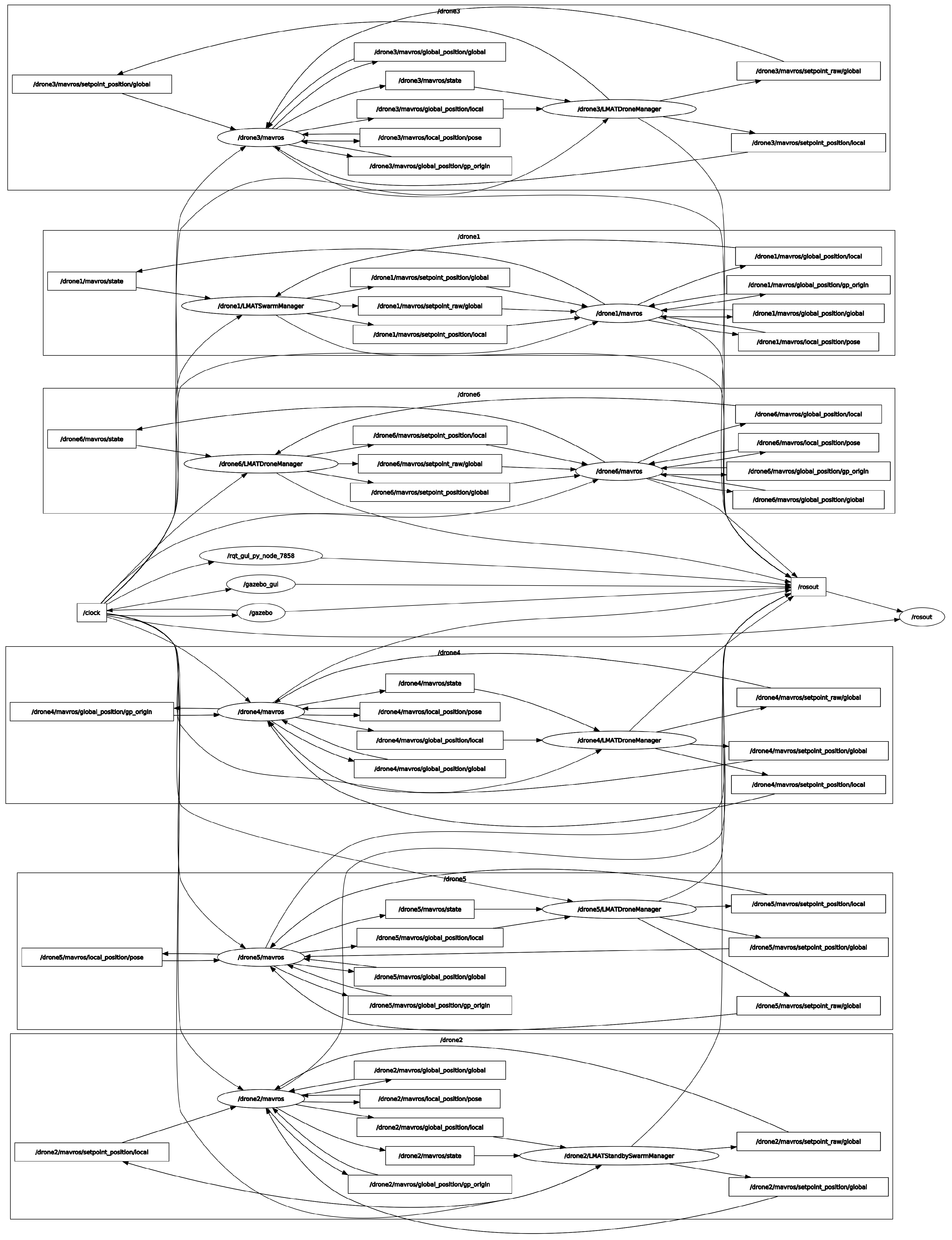
The swarm’s high availability is based on access to topics and services among all UAVs. Figure 20 shows the ROS communication graph for the entire swarm. Overall, we remark that the graph is connected, meaning that each UAV can access all the resources (topics and services) of another UAV. In addition, the graph is made up of six subgraphs, each corresponding to a UAV. Each subgraph is characterized by a complete graph, emphasizing the high availability of resources inside each UAV in the swarm and their distribution throughout the whole swarm. So, in the event of a failure, the mission will continue without interruption, thanks to the availability of resources on the other UAVs.

4.6. Comparative Study

In this subsection, we discuss the advantages and limitations of the proposed multi-UAV system.
Table 3 presents an evaluation of our system in relation to recent works proposed in [97,98,101]. The investigation criteria are defined in the column “Features”. Compared with [97,98], decentralized communication architecture as a single group offers greater flexibility. This gives the advantage of seamless migration to more resilient multigroup or multilevel architectures [11]. Since it is scalable, it could be used to gather large volumes of streaming data to be remotely integrated and processed in a big data infrastructure. Another advantage is that it eliminates dependency on the GCS and favors the Air2Air communication mode. In terms of onboard intelligence, our system is more autonomous than those proposed in [97,98,101]. It is the only one to offer a failover and continuity system in the event of one of the drones breaking down. It is self-organized according to the leader–followers hierarchical model and performs collaborative tasks based on a control consensus that regulates the actions of the drones in such a way as to promote convergence towards the desired goal.
Although the tests carried out show that our system is reliable, trustworthy, and consistently performs well, there are some limitations regarding the main features. The fact that the communication scheme is based on single-group architecture restricts the swarm’s mobility to limited areas, as the UAV leader acting as a relay must not move away from the GCS at the risk of losing the communication signal. What’s more, the communication mode is insecure and remains closed essentially to MAVLINK protocols, making it non-inter-operable with other connected objects. Added to this is the problem of coordinating UAV mobility, since our system does not offer a particular capability of collision avoidance for swarm flying. This obviously involves collecting data via various embedded sensors as well as data from external sources and calculating the most efficient maneuvers (roll/pitch/yaw) for the UAV to catty out to avoid colliding with its nearby neighbors. To deal with this problem, we need to think about integrating a collective navigation model (UAVs flying in tight formation) for obstacle and collision avoidance [11]. Complications emerge when the relative positions of the UAVs shift from one to another in a vast and highly dynamic swarm.

4.7. Key Problems and Limitations

In our test bed, we observed that the reliability and robustness of the proposed multi-UAV system is affected by the following limitations:
  • Asynchronous message passing interface: As this communication model does not implement instantaneous acknowledgment, it is therefore unreliable due to the risk of lost packets, data inconsistency, or out-of-time delivery. This can hamper the smooth running of the mission and optimal control of the swarm by the leader. In addition, the retry mechanisms of these buffered messages can lead to communication bottlenecks.
  • Network stability: A number of external factors, such as noise, wind, trees, hills, and the effect of highly urbanized areas, can alter network stability and cause communication delays due to degraded signal quality. In such situations, signal power can vary from extremely low to very high, with a greater probability of being close to zero.
  • Swarm mobility: The drones have a short communication range, which limits the swarm’s mobility in restricted areas. They must therefore always remain within the GCS transmission range. As a result, the drones will be close to each other. This can lead to collisions and signal interference. In practice, the proximity of one drone to another causes interference. This occurs when the signal from one drone’s receiver interferes with that of another drone. As a result, network stability is often disrupted, affecting not only latency but also the delivery of transmitted raw data and telemetry.
  • Energy constraints: Battery life has a direct impact on swarm performance. A drone with a low battery takes longer to react to cooperative actions and coordinate these movements with the others. This can hamper the convergence of consensus control and, in the worst case, lead to paralysis of the multi-UAV system when it comes to the leader drone.
  • Security: Our multi-UAV system is not secure, as the proposed communication scheme does not incorporate a security layer to protect data and the swarm. This vulnerability can be exploited by an attacker to initiate routing, jamming, and denial-of-service (DoS), Sybil, or Byzantine-type fault tolerance attacks.

5. Conclusions and Future Work

Autonomous aerial swarms are of tremendous interest to both industry and the scientific community since they provide a wide variety of potential. Setting them up is a matter that involves a couple of important challenges: communication, coordination, collaboration, and intelligence. The swarm needs to be fully equipped with a decentralized, scalable network infrastructure, enabling new UAVs to be easily added and/or removed. Maintaining the quality of the communication signal is another challenge arising from the swarm’s mobility. As a result, the UAVs must navigate in tight formation to avoid losing the signal, which is not often the case due to collisions. We also need to define a rule set based on a rigorous control consensus that regulates collective decision making, detects failures, and ensures the system’s reliability.
Although a variety of scientific works have already explored and investigated solutions to these problems, specific topics, such as mathematical formulation of swarm intelligence, self-organization, mission planning in a distributed manner, consensus control, and collective fault detection considerations, remain unaddressed. With growing interest in aerial swarms, these questions cannot be overlooked. That is why this paper is intended as a springboard and a solid cornerstone for any research work aimed at implementing a multi-UAV system whatever the field of application. This manuscript offers a thorough review of multi-UAV systems, with reference to the intelligence, applicability, and self-organization of aerial swarms. A collaborative swarming concept associated with autonomous swarm control in a distributed environment has been presented. This contribution deals with the complexity of environment assessment, distributed mission planning, communication paradigm, and finally, the consensus control problem to regulate the actions carried out by the drone fleet. The multi-UAV system presented in this paper is based on a decentralized single-group architecture that could be extended to other more robust types as a perspective. Compared with the current literature review, our swarming concept is more autonomous and resilient. Experimental tests have shown very conclusive results in terms of flight time reduction, energy consumption optimization, and area coverage during missions. It is true that the principles of flying in close formation are not covered in this work, but this paper could be extremely instructive for research into the use of autonomous swarms for collaborative missions.
The proposed swarming concept is freely accessible; the source code, demonstration videos, and documentation are accessible on github via this link: https://github.com/adoni91/autotarget.git (accessed on 20 September 2024).

Author Contributions

Conceptualization, W.Y.H.A. and S.L.; methodology, W.Y.H.A.; software, W.Y.H.A. and J.S.F.; validation, S.L., R.G. and T.D.K.; formal analysis, W.Y.H.A.; investigation, W.Y.H.A.; resources, Y.M. and J.S.F.; network infrastructure, J.S.F. and A.S.; writing—original draft preparation, W.Y.H.A.; writing—review and editing, W.Y.H.A., J.S.F. and Y.M.; visualization, R.G. and T.D.K.; supervision, S.L.; project administration, R.G. and T.D.K.; funding acquisition, R.G. and T.D.K.; logistic support, Y.M. and A.S. All authors have read and agreed to the published version of the manuscript.

Funding

This research was funded by CASUS Open X Projects.

Data Availability Statement

Data are contained within the article.

Conflicts of Interest

The authors declare no conflicts of interest.

Abbreviations

The following abbreviations are used in this manuscript:
UAVUnmanned Aerial Vehicle
GCSGround Control Station
VTOLVertical Take-Off and Landing
ROSRobot Operating System
SILSoftware-In-The Loop
LMATLocalization with a Mobile Anchor node based on Trilateration
MASMultiAgent System
UDPUser Datagram Protocol
FIFOFirst In–First Out
CPUCentral Processing Unit
C-UASCounter-Unmanned Aerial System
RAMRandom Access Memory
SPOFSingle Point Of Failure
RRTRapidly Random Tree

Appendix A

The following notations are used in this manuscript:
AArea
A i i t h Subarea of A
P k k-partition of the area
UAV i Drone i
q i State of UAV i
a i Altitude of UAV i
p i Perception capability of UAV i
S k Swarm composed of k UAVs
MMission
kNumber of UAVs
mNumber of jobs associated to M
pNumber of processor cores per UAV
j i i t h job of M
c i j j t h core of UAV j
t i Execution time of job i
t i j i t h task (ROS node) of UAV j
w i Workload of UAV i
w s Workload balancing of the swarm
w a v g Average workload

Appendix B

Table A1, Table A2 and Table A3 summarize the results for flight time O ( M ) , power consumption, and swarm latency θ with respect to coverage area A and k number of UAVs.
Table A1. Experimental results by varying the coverage area A from 400 m 2 to 1.2 km 2 .
A = 400 m 2 A = 800 m 2 A = 1.2 km 2
k Time
(min)
Energy Used 
per UAV (V)
Latency
(ms)
Time
(min)
Energy Used
per UAV (V)
Latency
(ms)
Time
(min)
Energy Used
per UAV (V)
Latency
(ms)
113.4225.2044.2829.0525.0243.8539.0825.2045.12
25.5611.0843.6610.3621.0245.4217.4525.2044.31
33.476.5542.788.5115.9842.7611.2518.6544.55
43.456.4244.706.328.3946.079.1110.3744.90
Table A2. Experimental results by varying the coverage area A from 1.6 km 2 to 2.4 km 2 .
A = 1.6 km 2 A = 2 km 2 A = 2.4 km 2
k Time
(min)
Energy Used 
Per UAV (V)
Latency
(ms)
Time
(min)
Energy Used
Per UAV (V)
Latency
(ms)
Time
(min)
Energy Used
Per UAV (V)
Latency
(ms)
148.0730.9944.2870.2345.2843.5592.3359.5344.32
221.4130.9143.6628.1640.6644.523753.4345.51
315.0925.0142.7819.3532.0742.5422.3937.1144.95
411.112.6344.9613.5215.3946.1617.1619.5344.81
Table A3. Experimental results by varying the coverage area A from 2.8 km 2 to 3.2 km 2 .
A = 2.8 km 2 A = 3.2 km 2
k Time
(min)
Energy Used 
Per UAV (V)
Latency
(ms)
Time
(min)
Energy Used
Per UAV (V)
Latency
(ms)
112379.3145.28156100.5943.88
258.2784.1443.8692.17133.0944.96
327.0944.9044.8532.1053.0443.68
419.2821.9445.7822.2525.3244.72

References

  1. Chen, X.; Tang, J.; Lao, S. Review of Unmanned Aerial Vehicle Swarm Communication Architectures and Routing Protocols. Appl. Sci. 2020, 10, 3661. [Google Scholar] [CrossRef]
  2. Abdelkader, M.; Güler, S.; Jaleel, H.; Shamma, J.S. Aerial Swarms: Recent Applications and Challenges. Curr. Robot. Rep. 2021, 2, 309–320. [Google Scholar] [CrossRef] [PubMed]
  3. Shakhatreh, H.; Sawalmeh, A.H.; Al-Fuqaha, A.; Dou, Z.; Almaita, E.; Khalil, I.; Othman, N.S.; Khreishah, A.; Guizani, M. Unmanned Aerial Vehicles (UAVs): A Survey on Civil Applications and Key Research Challenges. IEEE Access 2019, 7, 48572–48634. [Google Scholar] [CrossRef]
  4. Aljehani, M.; Inoue, M. Communication and Autonomous Control of Multi-UAV System in Disaster Response Tasks. In Agent and Multi-Agent Systems: Technology and Applications; Jezic, G., Kusek, M., Chen-Burger, Y.H.J., Howlett, R.J., Jain, L.C., Eds.; Springer International Publishing: Cham, Switzerland, 2018; Volume 74, pp. 123–132, Series Title: Smart Innovation, Systems and Technologies. [Google Scholar] [CrossRef]
  5. Chang, I.C.; Liao, C.S.; Yen, C.E. The Energy-Aware Multi-UAV Dispatch and Handoff Algorithm for Maximizing the Event Communication Time in Disasters. Appl. Sci. 2021, 11, 1054. [Google Scholar] [CrossRef]
  6. Câmara, D. Cavalry to the rescue: Drones fleet to help rescuers operations over disasters scenarios. In Proceedings of the 2014 IEEE Conference on Antenna Measurements & Applications (CAMA), Antibes Juan-les-Pins, France, 16–19 November 2014; pp. 1–4. [Google Scholar] [CrossRef]
  7. Hayajneh, A.M.; Zaidi, S.A.R.; McLernon, D.C.; Ghogho, M. Drone Empowered Small Cellular Disaster Recovery Networks for Resilient Smart Cities. In Proceedings of the 2016 IEEE International Conference on Sensing, Communication and Networking (SECON Workshops), London, UK, 27 June 2016; pp. 1–6. [Google Scholar] [CrossRef]
  8. Bjurling, O.; Granlund, R.; Alfredson, J.; Arvola, M.; Ziemke, T. Drone Swarms in Forest Firefighting: A Local Development Case Study of Multi-Level Human-Swarm Interaction. In Proceedings of the 11th Nordic Conference on Human-Computer Interaction: Shaping Experiences, Shaping Society, New York, NY, USA, 25–29 October 2020; NordiCHI ’20. pp. 1–7. [Google Scholar] [CrossRef]
  9. Rejeb, A.; Abdollahi, A.; Rejeb, K.; Treiblmaier, H. Drones in agriculture: A review and bibliometric analysis. Comput. Electron. Agric. 2022, 198, 107017. [Google Scholar] [CrossRef]
  10. Goodrich, P.; Betancourt, O.; Arias, A.C.; Zohdi, T. Placement and drone flight path mapping of agricultural soil sensors using machine learning. Comput. Electron. Agric. 2023, 205, 107591. [Google Scholar] [CrossRef]
  11. Adoni, W.Y.H.; Lorenz, S.; Fareedh, J.S.; Gloaguen, R.; Bussmann, M. Investigation of Autonomous Multi-UAV Systems for Target Detection in Distributed Environment: Current Developments and Open Challenges. Drones 2023, 7, 263. [Google Scholar] [CrossRef]
  12. Menouar, H.; Guvenc, I.; Akkaya, K.; Uluagac, A.S.; Kadri, A.; Tuncer, A. UAV-Enabled Intelligent Transportation Systems for the Smart City: Applications and Challenges. IEEE Commun. Mag. 2017, 55, 22–28. [Google Scholar] [CrossRef]
  13. Loianno, G.; Kumar, V. Cooperative Transportation Using Small Quadrotors Using Monocular Vision and Inertial Sensing. IEEE Robot. Autom. Lett. 2018, 3, 680–687. [Google Scholar] [CrossRef]
  14. Thiele, S.T.; Varley, N.; James, M.R. Thermal photogrammetric imaging: A new technique for monitoring dome eruptions. J. Volcanol. Geotherm. Res. 2017, 337, 140–145. [Google Scholar] [CrossRef]
  15. Chriki, A.; Touati, H.; Snoussi, H.; Kamoun, F. UAV-GCS Centralized Data-Oriented Communication Architecture for Crowd Surveillance Applications. In Proceedings of the 2019 15th International Wireless Communications & Mobile Computing Conference (IWCMC), Tangier, Morocco, 24–28 June 2019; pp. 2064–2069. [Google Scholar] [CrossRef]
  16. Scherer, J.; Yahyanejad, S.; Hayat, S.; Yanmaz, E.; Andre, T.; Khan, A.; Vukadinovic, V.; Bettstetter, C.; Hellwagner, H.; Rinner, B. An Autonomous Multi-UAV System for Search and Rescue. In Proceedings of the First Workshop on Micro Aerial Vehicle Networks, Systems, and Applications for Civilian Use, Florence Italy, 18 May 2015; DroNet ’15. pp. 33–38. [Google Scholar] [CrossRef]
  17. Adamopoulos, E.; Rinaudo, F. UAS-Based Archaeological Remote Sensing: Review, Meta-Analysis and State-of-the-Art. Drones 2020, 4, 46. [Google Scholar] [CrossRef]
  18. Patel, M.; Bandopadhyay, A.; Ahmad, A. Collaborative Mapping of Archaeological Sites Using Multiple UAVs. In Proceedings of the Intelligent Autonomous Systems 16, Zagreb, Croatia, 13–16 June 2022; Ang, M.H., Jr., Asama, H., Lin, W., Foong, S., Eds.; Springer: Cham, Switzerland, 2022. Lecture Notes in Networks and Systems. pp. 54–70. [Google Scholar] [CrossRef]
  19. Nyaaba, A.A.; Ayamga, M. Intricacies of medical drones in healthcare delivery: Implications for Africa. Technol. Soc. 2021, 66, 101624. [Google Scholar] [CrossRef]
  20. Mellinger, D.; Shomin, M.; Michael, N.; Kumar, V. Cooperative Grasping and Transport Using Multiple Quadrotors. In Distributed Autonomous Robotic Systems: The 10th International Symposium; Martinoli, A., Mondada, F., Correll, N., Mermoud, G., Egerstedt, M., Hsieh, M.A., Parker, L.E., Støy, K., Eds.; Springer Tracts in Advanced Robotics; Springer: Berlin/Heidelberg, Germany, 2013; pp. 545–558. [Google Scholar] [CrossRef]
  21. Ritz, R.; D’Andrea, R. Carrying a flexible payload with multiple flying vehicles. In Proceedings of the 2013 IEEE/RSJ International Conference on Intelligent Robots and Systems, Tokyo, Japan, 3–7 November 2013; pp. 3465–3471. [Google Scholar] [CrossRef]
  22. Saska, M.; Vonásek, V.; Chudoba, J.; Thomas, J.; Loianno, G.; Kumar, V. Swarm Distribution and Deployment for Cooperative Surveillance by Micro-Aerial Vehicles. J. Intell. Robot. Syst. 2016, 84, 469–492. [Google Scholar] [CrossRef]
  23. Citroni, R.; Di Paolo, F.; Livreri, P. A Novel Energy Harvester for Powering Small UAVs: Performance Analysis, Model Validation and Flight Results. Sensors 2019, 19, 1771. [Google Scholar] [CrossRef]
  24. Campo, L.V.; Ledezma, A.; Corrales, J.C. MCO Plan: Efficient Coverage Mission for Multiple Micro Aerial Vehicles Modeled as Agents. Drones 2022, 6, 181. [Google Scholar] [CrossRef]
  25. Petrlík, M.; Vonásek, V.; Saska, M. Coverage optimization in the Cooperative Surveillance Task using Multiple Micro Aerial Vehicles. In Proceedings of the 2019 IEEE International Conference on Systems, Man and Cybernetics (SMC), Bari, Italy, 6–9 October 2019; pp. 4373–4380. [Google Scholar] [CrossRef]
  26. Choudhary, G.; Sharma, V.; Gupta, T.; Kim, J.; You, I. Internet of Drones (IoD): Threats, Vulnerability, and Security Perspectives. arXiv 2018, arXiv:1808.00203. [Google Scholar] [CrossRef]
  27. Krichen, M.; Adoni, W.Y.H.; Mihoub, A.; Alzahrani, M.Y.; Nahhal, T. Security Challenges for Drone Communications: Possible Threats, Attacks and Countermeasures. In Proceedings of the 2022 2nd International Conference of Smart Systems and Emerging Technologies (SMARTTECH), Riyadh, Saudi Arabia, 9–11 May 2022; pp. 184–189. [Google Scholar] [CrossRef]
  28. Cline, T.; Lercel, D.; Karabiyik, U.; Dietz, J.E. The Current State of Counter Unmanned Aerial System Policy in the U.S. Int. J. Aviat. Aeronaut. Aerosp. 2020, 7, 11. [Google Scholar] [CrossRef]
  29. Kang, H.; Joung, J.; Kim, J.; Kang, J.; Cho, Y.S. Protect Your Sky: A Survey of Counter Unmanned Aerial Vehicle Systems. IEEE Access 2020, 8, 168671–168710. [Google Scholar] [CrossRef]
  30. De Campos, G.A.; Freire, E.S.; Cortés, M.I. Norm-based behavior modification in reflex agents. In Proceedings of the International Conference on Artificial Intelligence (ICAI). The Steering Committee of The World Congress in Computer Science, Computer, London, UK, 4–6 July 2012; p. 1. [Google Scholar]
  31. Qamar, S.; Khan, S.H.; Arshad, M.A.; Qamar, M.; Gwak, J.; Khan, A. Autonomous Drone Swarm Navigation and Multitarget Tracking With Island Policy-Based Optimization Framework. IEEE Access 2022, 10, 91073–91091. [Google Scholar] [CrossRef]
  32. Carpentiero, M.; Gugliermetti, L.; Sabatini, M.; Palmerini, G.B. A swarm of wheeled and aerial robots for environmental monitoring. In Proceedings of the 2017 IEEE 14th International Conference on Networking, Sensing and Control (ICNSC), Calabria, Italy, 16–18 May 2017; pp. 90–95. [Google Scholar] [CrossRef]
  33. Chung, S.J.; Paranjape, A.A.; Dames, P.; Shen, S.; Kumar, V. A Survey on Aerial Swarm Robotics. IEEE Trans. Robot. 2018, 34, 837–855. [Google Scholar] [CrossRef]
  34. Boggio-Dandry, A.; Soyata, T. Perpetual Flight for UAV Drone Swarms Using Continuous Energy Replenishment. In Proceedings of the 2018 9th IEEE Annual Ubiquitous Computing, Electronics & Mobile Communication Conference (UEMCON), New York, NY, USA, 8–10 November 2018; pp. 478–484. [Google Scholar] [CrossRef]
  35. Abdelkader, M.; Shaqura, M.; Ghommem, M.; Collier, N.; Calo, V.M.; Claudel, C.G. Optimal multi-agent path planning for fast inverse modeling in UAV-based flood sensing applications. In Proceedings of the 2014 International Conference on Unmanned Aircraft Systems (ICUAS), Orlando, FL, USA, 27–30 May 2014. [Google Scholar] [CrossRef]
  36. Manikandan, K.; Sriramulu, R. Optimized Path Planning Strategy to Enhance Security under Swarm of Unmanned Aerial Vehicles. Drones 2022, 6, 336. [Google Scholar] [CrossRef]
  37. Schranz, M.; Umlauft, M.; Sende, M.; Elmenreich, W. Swarm Robotic Behaviors and Current Applications. Front. Robot. AI 2020, 7, 36. [Google Scholar] [CrossRef] [PubMed]
  38. Ahmed, Z.; Khan, M.M.; Saeed, M.A.; Zhang, W. Consensus control of multi-agent systems with input and communication delay: A frequency domain perspective. ISA Trans. 2020, 101, 69–77. [Google Scholar] [CrossRef] [PubMed]
  39. Moussa, M.; Beltrame, G. On the robustness of consensus-based behaviors for robot swarms. Swarm Intell. 2020, 14, 205–231. [Google Scholar] [CrossRef]
  40. Wang, Z.; Zhang, H. Consensus error of the linear multi-agent systems with noises. In Proceedings of the 2017 Chinese Automation Congress (CAC), Jinan, China, 20–22 October 2017; pp. 5776–5780. [Google Scholar] [CrossRef]
  41. Galkin, B.; Kibilda, J.; DaSilva, L.A. UAVs as Mobile Infrastructure: Addressing Battery Lifetime. IEEE Commun. Mag. 2019, 57, 132–137. [Google Scholar] [CrossRef]
  42. Chen, Y.; Baek, D.; Bocca, A.; Macii, A.; Macii, E.; Poncino, M. A Case for a Battery-Aware Model of Drone Energy Consumption. In Proceedings of the 2018 IEEE International Telecommunications Energy Conference (INEC), Turino, Italy, 7–11 October 2018; pp. 1–8. [Google Scholar] [CrossRef]
  43. Bayındır, L. A review of swarm robotics tasks. Neurocomputing 2016, 172, 292–321. [Google Scholar] [CrossRef]
  44. Ducatelle, F.; Di Caro, G.A.; Förster, A.; Bonani, M.; Dorigo, M.; Magnenat, S.; Mondada, F.; O’Grady, R.; Pinciroli, C.; Rétornaz, P.; et al. Cooperative navigation in robotic swarms. Swarm Intell. 2014, 8, 1–33. [Google Scholar] [CrossRef]
  45. Digulescu, A.; Despina-Stoian, C.; Stănescu, D.; Popescu, F.; Enache, F.; Ioana, C.; Rădoi, E.; Rîncu, I.; Șerbănescu, A. New Approach of UAV Movement Detection and Characterization Using Advanced Signal Processing Methods Based on UWB Sensing. Sensors 2020, 20, 5904. [Google Scholar] [CrossRef]
  46. Chen, Y.; Wen, Z.; Peng, J.; Liu, X. Leader-follower congruence in loneliness, LMX and turnover intention. J. Manag. Psychol. 2016, 31, 864–879. [Google Scholar] [CrossRef]
  47. Shahzad, M.M.; Saeed, Z.; Akhtar, A.; Munawar, H.; Yousaf, M.H.; Baloach, N.K.; Hussain, F. A Review of Swarm Robotics in a NutShell. Drones 2023, 7, 269. [Google Scholar] [CrossRef]
  48. Alitappeh, R.J.; Jeddisaravi, K. Multi-robot exploration in task allocation problem. Appl. Intell. 2022, 52, 2189–2211. [Google Scholar] [CrossRef]
  49. Stan, A.C. A decentralised control method for unknown environment exploration using Turtlebot 3 multi-robot system. In Proceedings of the 2022 14th International Conference on Electronics, Computers and Artificial Intelligence (ECAI), Ploiesti, Romania, 30 June–1 July 2022; pp. 1–6. [Google Scholar] [CrossRef]
  50. Mohta, K.; Turpin, M.; Kushleyev, A.; Mellinger, D.; Michael, N.; Kumar, V. QuadCloud: A Rapid Response Force with Quadrotor Teams. In Experimental Robotics: The 14th International Symposium on Experimental Robotics; Hsieh, M.A., Khatib, O., Kumar, V., Eds.; Springer Tracts in Advanced Robotics; Springer International Publishing: Cham, Switzerland, 2016; pp. 577–590. [Google Scholar] [CrossRef]
  51. Zhang, J.; Campbell, J.F.; Sweeney II, D.C.; Hupman, A.C. Energy consumption models for delivery drones: A comparison and assessment. Transp. Res. Part Transp. Environ. 2021, 90, 102668. [Google Scholar] [CrossRef]
  52. Bio-inspired artificial intelligence: Theories, methods, and technologies. Choice Rev. Online 2009, 46, 46–4490. [CrossRef]
  53. Sion, A.; Reina, A.; Birattari, M.; Tuci, E. Controlling Robot Swarm Aggregation through a Minority of Informed Robots. arXiv 2022, arXiv:2205.03192. [Google Scholar] [CrossRef]
  54. Tahir, A.; Böling, J.; Haghbayan, M.H.; Plosila, J. Development of a Fault-Tolerant Control System for a Swarm of Drones. In Proceedings of the 2020 International Symposium ELMAR, Zadar, Croatia, 14–15 September 2020; pp. 79–82. [Google Scholar] [CrossRef]
  55. Jiang, Z.; Song, T.; Yang, B.; Song, G. Fault-Tolerant Control for Multi-UAV Exploration System via Reinforcement Learning Algorithm. Aerospace 2024, 11, 372. [Google Scholar] [CrossRef]
  56. Hwang, N.E.; Kim, H.J.; Kim, J.G. Centralized Task Allocation and Alignment Based on Constraint Table and Alignment Rules. Appl. Sci. 2022, 12, 6780. [Google Scholar] [CrossRef]
  57. Chakraa, H.; Leclercq, E.; Guérin, F.; Lefebvre, D. A Centralized Task Allocation Algorithm for a Multi-Robot Inspection Mission With Sensing Specifications. IEEE Access 2023, 11, 99935–99949. [Google Scholar] [CrossRef]
  58. Choi, H.L.; Brunet, L.; How, J.P. Consensus-Based Decentralized Auctions for Robust Task Allocation. IEEE Trans. Robot. 2009, 25, 912–926. [Google Scholar] [CrossRef]
  59. Zhang, Z.; Jiang, J.; Xu, H.; Zhang, W.A. Distributed dynamic task allocation for unmanned aerial vehicle swarm systems: A networked evolutionary game-theoretic approach. Chin. J. Aeronaut. 2024, 37, 182–204. [Google Scholar] [CrossRef]
  60. Peng, Q.; Wu, H.; Xue, R. Review of Dynamic Task Allocation Methods for UAV Swarms Oriented to Ground Targets. Complex Syst. Model. Simul. 2021, 1, 163–175. [Google Scholar] [CrossRef]
  61. Alsolami, F.; Alqurashi, F.A.; Hasan, M.K.; Saeed, R.A.; Abdel-Khalek, S.; Ben Ishak, A. Development of Self-Synchronized Drones’ Network Using Cluster-Based Swarm Intelligence Approach. IEEE Access 2021, 9, 48010–48022. [Google Scholar] [CrossRef]
  62. Khosiawan, Y.; Park, Y.; Moon, I.; Nilakantan, J.M.; Nielsen, I. Task scheduling system for UAV operations in indoor environment. Neural Comput. Appl. 2019, 31, 5431–5459. [Google Scholar] [CrossRef]
  63. Poudel, S.; Moh, S. Task assignment algorithms for unmanned aerial vehicle networks: A comprehensive survey. Veh. Commun. 2022, 35, 100469. [Google Scholar] [CrossRef]
  64. You, R.; Tang, M.; Guo, S.; Cui, G. Proportional Integral Observer-based Consensus Control of Discrete-time Multi-agent Systems. Int. J. Control. Autom. Syst. 2022, 20, 1461–1472. [Google Scholar] [CrossRef]
  65. Chen, Y.; Deng, T. Leader-Follower UAV formation flight control based on feature modelling. Syst. Sci. Control. Eng. 2023, 11, 2268153. [Google Scholar] [CrossRef]
  66. Dong, X.; Yu, B.; Shi, Z.; Zhong, Y. Time-Varying Formation Control for Unmanned Aerial Vehicles: Theories and Applications. IEEE Trans. Control. Syst. Technol. 2015, 23, 340–348. [Google Scholar] [CrossRef]
  67. Hamadi, H.; Lussier, B.; Fantoni, I.; Francis, C. Data fusion fault tolerant strategy for a quadrotor UAV under sensors and software faults. ISA Trans. 2022, 129, 520–539. [Google Scholar] [CrossRef]
  68. Zuo, Y.; Yao, W.; Chang, Q.; Zhu, X.; Gui, J.; Qin, J. Voting-Based Scheme for Leader Election in Lead-Follow UAV Swarm with Constrained Communication. Electronics 2022, 11, 2143. [Google Scholar] [CrossRef]
  69. Almansoori, A.; Alkilabi, M.; Tuci, E. On the evolution of mechanisms for three-option collective decision-making in a swarm of simulated robots. In Proceedings of the Genetic and Evolutionary Computation Conference, Lisbon, Portugal, 15–19 July 2023; GECCO ’23. pp. 4–12. [Google Scholar] [CrossRef]
  70. Hall, O.; Wahab, I. The Use of Drones in the Spatial Social Sciences. Drones 2021, 5, 112. [Google Scholar] [CrossRef]
  71. Rubenstein, M.; Cornejo, A.; Nagpal, R. Robotics. Programmable self-assembly in a thousand-robot swarm. Science 2014, 345, 795–799. [Google Scholar] [CrossRef]
  72. Carrillo-Zapata, D.; Sharpe, J.; Winfield, A.F.T.; Giuggioli, L.; Hauert, S. Toward Controllable Morphogenesis in Large Robot Swarms. IEEE Robot. Autom. Lett. 2019, 4, 3386–3393. [Google Scholar] [CrossRef]
  73. Slavkov, I.; Carrillo-Zapata, D.; Carranza, N.; Diego, X.; Jansson, F.; Kaandorp, J.; Hauert, S.; Sharpe, J. Morphogenesis in robot swarms. Sci. Robot. 2018, 3, eaau9178. [Google Scholar] [CrossRef]
  74. Bentley, J.L. Multidimensional divide-and-conquer. Commun. ACM 1980, 23, 214–229. [Google Scholar] [CrossRef]
  75. Varga, M.; Bogdan, S.; Dragojević, M.; Miklić, D. Collective search and decision-making for target localization. Math. Comput. Model. Dyn. Syst. 2012, 18, 51–65. [Google Scholar] [CrossRef]
  76. Adoni, W.Y.H.; Fareedh, J.S.; Lorenz, S.; Gloaguen, R.; Kühne, T.D. Autotarget*: A Distributed Robot Operating System Framework for Autonomous Aerial Swarms. In Proceedings of the 2024 21st International Conference on Ubiquitous Robots (UR), New York, NY, USA, 24–27 June 2024; pp. 153–160. [Google Scholar] [CrossRef]
  77. Viseras, A.; Garcia, R. DeepIG: Multi-Robot Information Gathering With Deep Reinforcement Learning. IEEE Robot. Autom. Lett. 2019, 4, 3059–3066. [Google Scholar] [CrossRef]
  78. Singh, A.; Krause, A.; Guestrin, C.; Kaiser, W.J. Efficient Informative Sensing using Multiple Robots. J. Artif. Intell. Res. 2009, 34, 707–755. [Google Scholar] [CrossRef]
  79. Xu, D.; Guo, Y.; Yu, Z.; Wang, Z.; Lan, R.; Zhao, R.; Xie, X.; Long, H. PPO-Exp: Keeping Fixed-Wing UAV Formation with Deep Reinforcement Learning. Drones 2023, 7, 28. [Google Scholar] [CrossRef]
  80. Michael, N.; Shen, S.; Mohta, K.; Mulgaonkar, Y.; Kumar, V.; Nagatani, K.; Okada, Y.; Kiribayashi, S.; Otake, K.; Yoshida, K.; et al. Collaborative mapping of an earthquake-damaged building via ground and aerial robots. J. Field Robot. 2012, 29, 832–841. [Google Scholar] [CrossRef]
  81. Perez, D.; Maza, I.; Caballero, F.; Scarlatti, D.; Casado, E.; Ollero, A. A Ground Control Station for a Multi-UAV Surveillance System. J. Intell. Robot. Syst. 2013, 69, 119–130. [Google Scholar] [CrossRef]
  82. Kishk, M.A.; Bader, A.; Alouini, M.S. On the 3-D Placement of Airborne Base Stations Using Tethered UAVs. arXiv 2019, arXiv:1907.04299. [Google Scholar] [CrossRef]
  83. Reitsma, R.; Trubin, S.; Mortensen, E. Weight-proportional Space Partitioning Using Adaptive Voronoi Diagrams. GeoInformatica 2007, 11, 383–405. [Google Scholar] [CrossRef]
  84. Soltanolkotabi, M.; Candés, E.J. A geometric analysis of subspace clustering with outliers. Ann. Stat. 2012, 40, 2195–2238. [Google Scholar] [CrossRef]
  85. Wardana, T.K.; Arkeman, Y.; Priandana, K.; Kurniawan, F.; Prabowo, G.S.; Hasim, F. Implementation of DBSCAN and K-Means Algorithm for Clustering Agricultural Drone Flying Areas. In The 18th IMT-GT International Conference on Mathematics, Statistics and their Applications; Sciendo: Warsaw, Poland, 2024; pp. 117–122. [Google Scholar] [CrossRef]
  86. Comaniciu, D.; Meer, P. Mean shift: A robust approach toward feature space analysis. IEEE Trans. Pattern Anal. Mach. Intell. 2002, 24, 603–619. [Google Scholar] [CrossRef]
  87. Walker, D.W.; Dongarra, J.J. MPI: A standard message passing interface. Supercomputer 1996, 12, 56–68. [Google Scholar]
  88. Garey, M.R.; Johnson, D.S.; Stockmeyer, L. Some simplified NP-complete problems. In Proceedings of the Sixth Annual ACM Symposium on Theory of Computing, Seattle, WA, USA, 30 April–2 May 1974; STOC ’74. pp. 47–63. [Google Scholar] [CrossRef]
  89. Adoni, W.Y.H.; Nahhal, T.; Krichen, M.; El byed, A.; Assayad, I. DHPV: A distributed algorithm for large-scale graph partitioning. J. Big Data 2020, 7, 76. [Google Scholar] [CrossRef]
  90. Adoni, W.Y.H.; Nahhal, T.; Aghezzaf, B.; Elbyed, A. The MapReduce-based approach to improve the shortest path computation in large-scale road networks: The case of A* algorithm. J. Big Data 2018, 5, 16. [Google Scholar] [CrossRef]
  91. Quigley, M.; Conley, K.; Gerkey, B.P.; Faust, J.; Foote, T.; Leibs, J.; Wheeler, R.; Ng, A.Y. ROS: An open-source Robot Operating System. In Proceedings of the ICRA Workshop on Open Source Software, Kobe, Japan, 12–17 May 2009. [Google Scholar]
  92. Fent, P.; Renen, A.v.; Kipf, A.; Leis, V.; Neumann, T.; Kemper, A. Low-Latency Communication for Fast DBMS Using RDMA and Shared Memory. In Proceedings of the 2020 IEEE 36th International Conference on Data Engineering (ICDE), Dallas, TX, USA, 20–24 April 2020; pp. 1477–1488. [Google Scholar] [CrossRef]
  93. Ladeira, M.; Ouhammou, Y.; Grolleau, E. RoBMEX: ROS-based modelling framework for end-users and experts. J. Syst. Archit. 2021, 117, 102089. [Google Scholar] [CrossRef]
  94. Ye, Y.; Wang, Z.; Lu, X. Leader–Follower Congruence in Work Engagement and Leader–Member Exchange: The Moderating Role of Conscientiousness of Followers. Front. Psychol. 2021, 12, 666765. [Google Scholar] [CrossRef]
  95. Adoni, W.Y.H.; Nahhal, T.; Aghezzaf, B.; Elbyed, A. MRA*: Parallel and Distributed Path in Large-Scale Graph Using MapReduce-A* Based Approach. In Proceedings of the Ubiquitous Networking, Casablance, Morocco, 9–12 May 2017; Springer: Cham, Switzerland, 2017. Lecture Notes in Computer Science. pp. 390–401. [Google Scholar] [CrossRef]
  96. Mustafa, M.E.G.; Talab, S.A. The Effect of Queuing Mechanisms First in First out (FIFO), Priority Queuing (PQ) and Weighted Fair Queuing (WFQ) on Network’s Routers and Applications. Wirel. Sens. Netw. 2016, 8, 77. [Google Scholar] [CrossRef]
  97. Jacobsen, R.H.; Matlekovic, L.; Shi, L.; Malle, N.; Ayoub, N.; Hageman, K.; Hansen, S.; Nyboe, F.F.; Ebeid, E. Design of an Autonomous Cooperative Drone Swarm for Inspections of Safety Critical Infrastructure. Appl. Sci. 2023, 13, 1256. [Google Scholar] [CrossRef]
  98. Ramos, J.; Ribeiro, R.; Safadinho, D.; Barroso, J.; Rabadão, C.; Pereira, A. Distributed Architecture for Unmanned Vehicle Services. Sensors 2021, 21, 1477. [Google Scholar] [CrossRef] [PubMed]
  99. Jiang, J.; Han, G.; Xu, H.; Shu, L.; Guizani, M. LMAT: Localization with a Mobile Anchor Node Based on Trilateration in Wireless Sensor Networks. In Proceedings of the 2011 IEEE Global Telecommunications Conference—GLOBECOM 2011, Houston, TX, USA, 5–9 December 2011; pp. 1–6. [Google Scholar] [CrossRef]
  100. Cabreira, T.; Brisolara, L.; Ferreira, P.R., Jr. Survey on Coverage Path Planning with Unmanned Aerial Vehicles. Drones 2019, 3, 4. [Google Scholar] [CrossRef]
  101. Sial, M.B.; Zhang, Y.; Wang, S.; Ali, S.; Wang, X.; Yang, X.; Liao, Z.; Yang, Z. Bearing-Based Distributed Formation Control of Unmanned Aerial Vehicle Swarm by Quaternion-Based Attitude Synchronization in Three-Dimensional Space. Drones 2022, 6, 227. [Google Scholar] [CrossRef]
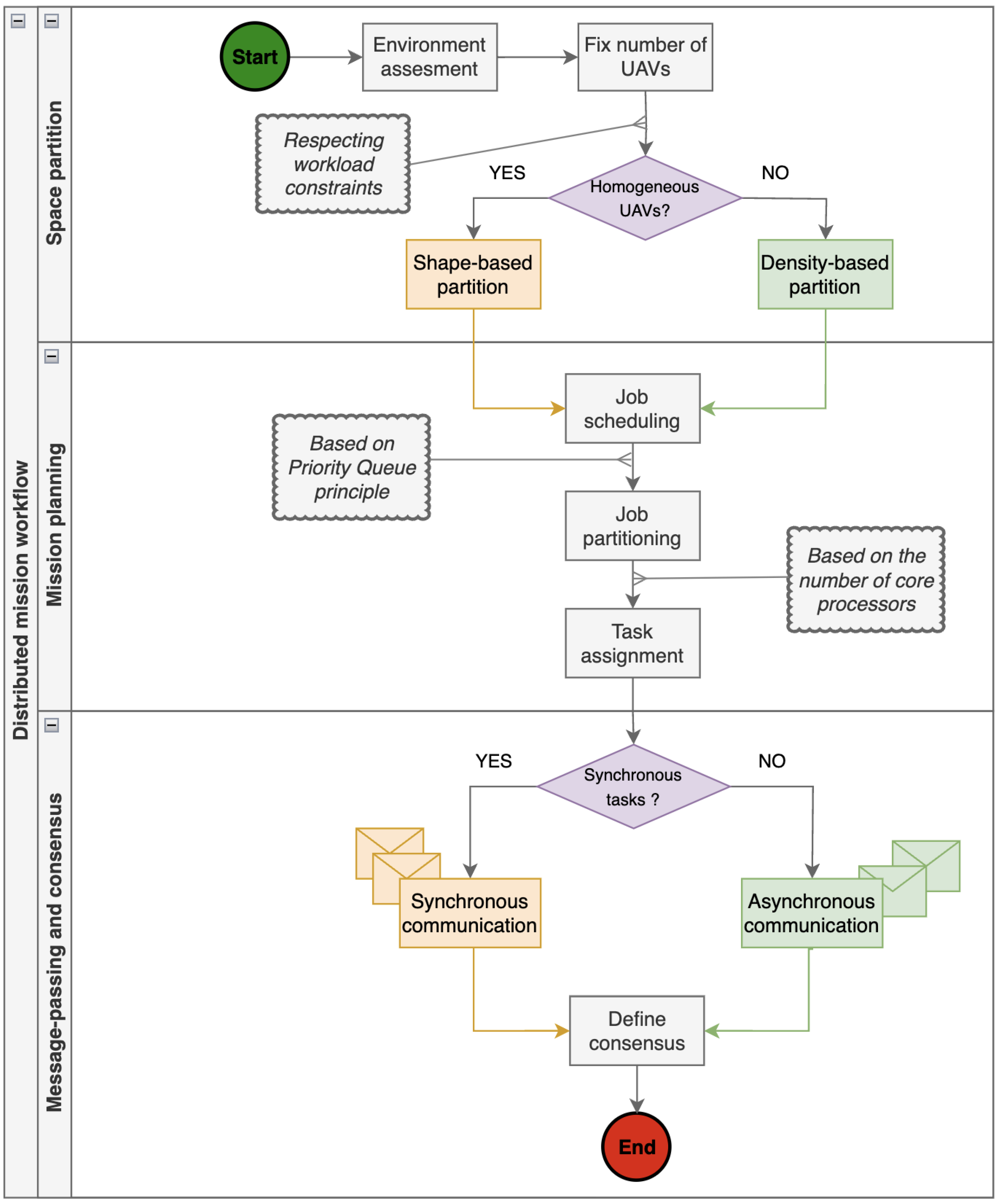
Figure 1. Proposed swarming workflow. It consists of three main stages: (1) space partitioning stage, (2) mission planning stage, and (3) communication and consensus control stage.
Drones 08 00575 g001
Figure 2. Autonomous UAV-based model-reflex agent.
Drones 08 00575 g002
Figure 3. Illustration of the shape-based partition of A for k-drone swarm [11].
Drones 08 00575 g003
Figure 4. Swarm configuration for high-level mission parallelism.
Drones 08 00575 g004
Figure 5. Communication topology: (a) Synchronous communication. (b) Asynchronous communication.
Drones 08 00575 g005
Figure 6. Architecture design of our multi-UAV system.
Drones 08 00575 g006
Figure 7. Service thread pool management of the swarm. Two threads are allocated for each service. Follower-to-follower services are performed in a synchronous manner. While leader-to-leader services are asynchronous.
Drones 08 00575 g007
Figure 8. Communication model of the swarm based on single-group architecture.
Drones 08 00575 g008
Figure 9. Message passing interface for swarm communication via MAVLink.
Drones 08 00575 g009
Figure 10. Execution workflow of the swarm services based on leader–followers hierarchy.
Drones 08 00575 g010
Figure 11. State transition diagram of the standby leader UAV. The standby UAV passes to active mode when one of the three events is detected.
Drones 08 00575 g011
Figure 12. Cooperative execution workflow of leader UAVs for fault-tolerance policy management.
Drones 08 00575 g012
Figure 13. Illustration of task failure management for the followers UAV 2 and UAV 3 . The SwarmManager reschedules the failed jobs on UAV 1 and UAV 4 according to the FIFO and priority order queue.
Drones 08 00575 g013
Figure 14. UAV Swarm used for the experimental tests: (a) Real swarm used for reliability and deployment testing. It consists of two homogeneous quadrotors and based on ardupilot architecture. (b) virtual swarm used for the simulation. It consists of two leaders and four follower UAVs.
Drones 08 00575 g014
Figure 15. LMAT coverage operation with the 2-UAV swarm in outdoor environment. The green UAV operates on the left side while the black one on the right.
Drones 08 00575 g015
Figure 16. Swarming version of the coverage mission with a 4-UAV swarm. The mission is performed simultaneously across the four follower UAVs.
Drones 08 00575 g016
Figure 17. Time complexity O ( M ) of the LMAT coverage algorithm with varying number of follower UAVs k = 1 . . 4 .
Drones 08 00575 g017
Figure 18. Swarm energy consumption from small to large areas ( | A | { 0.4 ; 0.8 ; 1.2 } ). Small area is covered by (a), while (b,c) show the results for large areas.
Drones 08 00575 g018
Figure 19. Network bandwidth (pkts) of the swarm based on the number of UAV k = 1 . . 4 .
Drones 08 00575 g019
Figure 20. ROS communication graph of the six-UAV swarm. Each block represents a communication subgraph of each UAV. The nodes and arcs within each block represent the services/topics and their interactions.
Drones 08 00575 g020
Table 1. Comparative methods of collective decision making and task dependency problem in autonomous drone swarming.
AspectMethodsChallengesAdvantagesWeak Points
Fault detection-Redundancy-based monitoring [54]
-AI-based anomaly detection [55]
-Significant supervision and redundancy
of drone actions and status
-Real-time processing of data fusion
-Real-time recognition of
anomalies
-Proactive failure management
-Misdiagnosis of faults or
false positives leading to
complete mission failures
Task allocation-Centralized allocation [56,57]
-Decentralized allocation [58]
-Dynamic allocation [59,60]
-Resilience to faults
-Communication overheads
-Reassignment of tasks on available resources
-Highly resource efficient
-Adaptive fault response
-Misallocation of tasks leads
to bottlenecks or unbalanced
resources and workloads
Task synchronization-Time-based synchronization [61]
-Event-based synchronization [62,63]
-Reliability of communication network
-Time constraints
-Sharing global timing clocks
-Fine-tuned coordination for
intricate task planning
-Adaptive task allocation
-Synchronization delays or
misaligned tasks cause mission
failure
Consensus control-Proportional consensus [64]
-Leader–Follower consensus [65]
-Time-delayed consensus [66]
-Time-consuming communication
-Vulnerable to erroneous consensus
-Convergence rapidity
-Uniform behaviors throughout
the swarm
-Convergence to optimal
decision making
-Vulnerability to hardware
failure or loss of communication
-Divergent behavior quickly
affects the drones swarm
Collective perception-Data fusion [67]
-Voting mechanism [68]
-Distributed perception [69]
-Merging multisource data from
multi-UAV sensors
-Holistic understanding of
the environment
-Coordinated swarm mobility
-Incoherent perceptions
may result in navigation errors
or collisions
Table 2. Network latency of the swarm with varying number of drones k = 1 . . 4 .
Time Delay θ (ms)
pktsk = 1k = 2k = 3k = 4
5 × 10 3 40.5445.2841.9246.84
10 × 10 3 45.5041.1849.4846.20
15 × 10 3 44.2843.1645.8242.32
20 × 10 3 49.0744.2442.8242.84
25 × 10 3 42.7645.9846.9443.96
30 × 10 3 43.3443.6645.0947.24
Average time (ms)44.2443.4145.0144.9
Mean latency (ms)44.39
Table 3. Comparative key features of our multi-UAV system versus work carried out in [97,98,101].
FeaturesOur SystemSial [101]Rune [97]João [98]
Programming
framework
ROS1
ROS2
Network
architecture
Centralized
Decentralized
Communication
mode
Air2Ground
Air2Air
Air2Cloud
Secure
Swarm
intelligence
Collaborative
Consensus control
Resilience
Self-organized
Failover system
Collision avoidance
Proofs of
concept
Simulation
Real-world
Disclaimer/Publisher’s Note: The statements, opinions and data contained in all publications are solely those of the individual author(s) and contributor(s) and not of MDPI and/or the editor(s). MDPI and/or the editor(s) disclaim responsibility for any injury to people or property resulting from any ideas, methods, instructions or products referred to in the content.