Article

MPC-Based Dynamic Trajectory Spoofing for UAVs

by
Bo Hou
1,2,*,
Zhongjie Yin
1,
Xiaolong Jin
1,
Zhiliang Fan
1 and
Haiyang Wang
1
1
Rocket Force University of Engineering, Xi’an 710025, China
2
Northwestern Polytechnical University, Xi’an 710072, China
*
Author to whom correspondence should be addressed.
Drones 2024, 8(10), 602; https://doi.org/10.3390/drones8100602
Submission received: 15 September 2024 / Revised: 15 October 2024 / Accepted: 16 October 2024 / Published: 19 October 2024
(This article belongs to the Special Issue Path Planning, Trajectory Tracking and Guidance for UAVs: 2nd Edition)

Abstract

:
Navigation spoofing has been widely utilized in unmanned aircraft vehicle (UAV) countermeasures, due to its advantages of covertness, effectiveness, and dynamic trajectory control ability. However, existing research faces two primary challenges. Firstly, sudden changes in the target UAV’s trajectory can result in a significant degradation in the spoofing performance, which may enable the onboard inertial components to detect and identify the ongoing spoofing attempts. Secondly, gradual accumulation of control errors over time degenerates the spoofing effect. To address these problems, we propose a dynamic trajectory spoofing approach for UAVs based on model predictive control (MPC), which progressively steers the UAVs towards the predetermined trajectory of the spoofer. Simulation results demonstrate a substantial enhancement in dynamic trajectory control performance and decrease in accumulation error compared to the existing methods.

1. Introduction

The decreasing manufacturing costs, size miniaturization, and enhanced ease of operation of UAVs have significantly boosted their popularity. This popularity spans various domains, including aerial photography, flood rescue operations, law enforcement, and aerial reconnaissance [1,2,3,4,5]. However, the illicit use of UAVs poses substantial threats in both civilian and military contexts. UAVs are used to target critical civilian infrastructure such as oil fields, airports and nuclear power plants. In military operations, they are extensively utilized for reconnaissance, targeted strikes, and long-range assaults. Consequently, the development of counter-UAV technologies has emerged as a critical area of research.
Most UAVs rely on global navigation satellite system (GNSS) signals, which provide position, velocity, and time information [6,7,8,9], to maintain steady and accurate flight control. However, the signals transmitted from navigation satellites are weak and susceptible to interference. Moreover, civilian GNSS signals are publicly accessible, making it feasible to create counterfeit GNSS signals as a means to disrupt UAV flight control. This tactic, known as navigation spoofing, is the process of intruding into a UAV’s flight control link by transmitting counterfeit satellite signals, thereby misleading the UAV’s receiver into providing incorrect location, speed, or time information [10]. Due to the difficulty in detecting spoofing [11], its capacity to manipulate the dynamics of UAVs, and its high success rate, it has emerged as a significant countermeasure for UAVs, noteworthy for its covert nature, effectiveness, and ability to control dynamic trajectories.
Research interest in GNSS spoofing techniques arose in the early 2000s. Warner and Johnston demonstrated that civilian GPS spoofing attacks can be easily implemented with a satellite simulator [12]. The same research group proposed seven potential countermeasures against GPS spoofing [13], including monitoring absolute GPS signal strength, checking relative GPS signal strength, and conducting time comparisons. Humphreys outlined the necessary hardware and software components for spoofing and developed a portable GNSS spoofing jamming device [14]. Shepard et al. [15] conducted the first field test of GPS spoofing on a UAV in publicly available literature, successfully hijacking the UAV by altering its perceived location. The effects of GNSS spoofing on UAVs were measured through various experimental scenarios in [16] and [17]. Low-cost software-defined radio (SDR) platforms have been widely employed as spoofing signal generators, and their feasibility has been verified by field experiments [18,19]. To address the UAV intrusion problems, He et al. proposed a novel “repulsion” method that involves the deployment of sensors and spoofing devices to establish a no-fly zone [20]. In contrast to most research on multi-rotator UAVs, Chae et al. investigated the GNSS spoofing method for fixed-wing drones, and proposed two flight redirection strategies [21]. Alharasees et al. conducted a series of studies on human factors in UAV operations, and noted that as autonomy increases and artificial intelligence is applied to UAV flight control, there is a corresponding reduction in both operators’ workload and vigilance [22,23,24]. This vigilance reduction, in turn, increases the potential for spoofing.
Where there is a spear, there is a shield. Numerous methods and algorithms have been proposed to detect, identify, and mitigate spoofing attacks on UAVs. These methods include the use of machine learning algorithms, array antennas, visual odometry, inertial navigation systems (INS), magnetometer sensors, and barometer sensors [25,26,27,28,29,30,31,32,33]. As a cost-effective and reliable solution, an increasing number of newly developed UAVs are equipped with inertial navigation modules. This equipment improves their navigational capabilities and enhances their resilience against spoofing attempts. Kerns proposed a comprehensive model for spoofing UAVs integrated with GNSS/INS components, which is capable of conducting trajectory spoofing and incorporates a UAV state estimator and spoofing controller [34]. Guo conducted a mathematical analysis of the trajectory tracking errors in the model referenced in [34] and designed a position tracking controller [35]. By selecting suitable control gain matrices, the team optimized the spoofing effect and reduced state errors. Furthermore, Guo et al. theoretically proved that when the acceleration component of the counterfeit GPS signal accounts for the difference between the UAV’s current acceleration and the spoofing control input, the target UAV can be covertly spoofed [36]. Gao introduced a covert spoofing strategy that enhances spoofing effectiveness and enables directional control over UAV flight [37]. The proposed approach can swiftly guide tightly-coupled GNSS/IMU UAVs toward specific directions by employing a directional spoofing strategy. Geng proposed a directional spoofing method for loosely integrated INS/GNSS UAVs [38].
The primary objective of spoofing non-cooperative UAVs is to gain control over their dynamics. Consequently, compared to directional spoofing, dynamic trajectory spoofing is not only of greater significance in real-world applications but also more challenging. It is worth noting that the trajectory spoofing methods described in existing the literature, such as [34] and [36], exhibit an error accumulation phenomenon, whereby the difference between the actual trajectory of the UAV and the preset one of the spoofer escalates over time. The escalating discrepancy poses a significant setback for the effectiveness and efficiency of the spoofing operation. The duration of the spoofing operation remains uncertain. Additionally, the inertial components of UAVs may identify the difference between the estimated trajectory and its reference trajectory. This can result in the failure of the spoofing attempt. Furthermore, the existing method demonstrates a delayed response when the UAV undergoes sudden acceleration changes, leading to significant spoofing errors between the actual trajectory and the spoofer’s desired one, which means significant degradation in the spoofing performance. Consequently, this discrepancy hinders the consistent alignment of the UAV with the spoofer’s preset path. To address these issues, we propose a UAV dynamic trajectory spoofing method based on model predictive control. The main contributions of this paper are as follows.
(1)
A novel non-cooperative UAV dynamic trajectory spoofing method is proposed, which significantly reduces the errors between the actual trajectory of the UAV and the desired trajectory of the spoofer.
(2)
An MPC algorithm has been employed to optimize the spoofing operation. Control input of the spoofing model is optimized using predictive information, enabling the UAV to follow the intended trajectory of the spoofer more precisely.
(3)
Extensive simulation experiments have been conducted in various scenarios, demonstrating that the proposed method significantly enhances the spoofing effect, leading to a considerable reduction in cumulative errors and a marked improvement in spoofing accuracy.
The remainder of the article is organized as follows. Section 2 presents and analyses the UAV trajectory control model. Section 3 introduces a novel UAV dynamic spoofing method based on MPC. Numerical simulations are provided in Section 4, where the results of the proposed method are compared with existing algorithms. In Section 5, we summarize the paper, and concluding remarks are stated.

2. UAV Trajectory Control Model

Assume that the UAV’s trajectory dynamics satisfy the double-integrator kinematic model in a two-dimensional plane:
x ˙ ( k ) = A x ( k ) + B a ( k ) ,
where x = [ r x r y v x v y ] T is the state of the UAV, r x and r y are the positions of x and y axis respectively, v x and v y are the velocities, a = [ a x a y ] T , A = [ 0 2 × 2 I 2 × 2 0 2 × 2 0 2 × 2 ] , B = [ 0 2 × 2 I 2 × 2 ] , I n × n and 0 m × n stand for identity and
This paper considers UAVs equipped with both GNSS receivers and INS components. The INS can be utilized to identify potential GNSS spoofing attempts, while GNSS is leveraged to correct the accumulated errors in the INS output. The integrated navigation module enhances both navigation precision and anti-spoofing capabilities. For UAVs equipped with INS, its measured acceleration features a zero bias, indicating that the acceleration output by the INS can be described as
a m ( k ) = a ( k ) b ( k ) ,
where b = [ b x b y ] T is the zero bias, a is the actual acceleration of the UAV, and a m is the measurement output of the onboard inertial component.
Most UAVs use the Kalman filtering techniques [37,38,39,40,41,42] to integrate the state information measured by INS with that outputted by the GNSS receivers. In each localization process, the UAV obtains its current state from the GNSS receiver as x * = [ r x * r y * v x * v y * ] T . The integration procedure can be described by
[ x ^ ˙ ( k ) b ^ ˙ ( k ) ] = [ A B 0 0 ] [ x ^ ( k ) b ^ ( k ) ] + L ( x * ( k ) x ^ ( k ) ) + [ B 0 ] a m ( k ) ,
where x ^ is the UAV’s estimation of its own state, and b ^ is estimation of the zero bias of the measurements of inertial devices. L is the steady state gain matrix of the Kalman filter for the UAV, which can be determined by the following two steps.
Step 1: By solving the algebraic Riccati equation
A e P + P A e T + Q P C T R 1 C P = 0 ,
the UAV estimation error covariance P can be obtained, where A e = [ A B 0 0 ] , and C = [ I 0 ] is measured matrix. Q is the system noise matrix, which takes the following form:
Q = [ 0 3 × 3 0 3 × 3 0 3 × 3 0 3 × 3 Q 1 0 3 × 3 0 3 × 3 0 3 × 3 Q 2 ] .
Here
Q 1 = [ σ a , x 2 0 0 0 σ a , y 2 0 0 0 σ a , z 2 ] ,   Q 2 = [ σ b , x 2 0 0 0 σ b , y 2 0 0 0 σ b , z 2 ] ,
σ a , x 2 , σ a , y 2 , σ a , z 2 are acceleration noise errors of X, Y, Z axes, and σ b , x 2 , σ b , y 2 , σ b , z 2 are zero-bias instability of accelerometers of X, Y, Z axes.
In Equation (4), R is the measurement noise matrix, which the takes following form:
R = [ R 1 0 3 × 3 0 3 × 3 R 2 ] ,
with
R 1 = [ σ r , x 2 0 0 0 σ r , y 2 0 0 0 σ r , z 2 ] ,   R 2 = [ σ v , x 2 0 0 0 σ v , y 2 0 0 0 σ v , z 2 ] ,
where σ r , x 2 , σ r , y 2 , σ r , z 2 are position errors of X, Y, Z axes, and σ v , x 2 , σ v , y 2 , σ v , z 2 are velocity errors of X, Y, Z axes.
Step 2: Using the obtained UAV estimation error covariance P , the steady state gain matrix L of the Kalman filter for the UAV can be calculated with
L = P C T R 1 .
Without loss of generality, we assume that the UAV to be spoofed has a preset reference flight trajectory, and the reference trajectory also satisfies the double-integrator kinematics as follows:
x ¯ ˙ ( k ) = A x ¯ ( k ) + B a ¯ ( k ) ,
where x ¯ = [ r ¯ x r ¯ y v ¯ x v ¯ y ] T is the state of the UAV’s preset reference trajectory, and a ¯ is the corresponding acceleration with composition structure similar to a .
Most trajectory trackers are designed using a proportional (P) control strategy
a ( k ) = K ( x ^ ( k ) x ¯ ( k ) ) ,
where K is the controller gain. The actual trajectory of the UAV can be obtained by taking a ( k ) into Equation (1).

3. UAV Dynamic Trajectory Spoofing

Dynamic trajectory spoofing refers to moment-by-moment spoofing of UAVs, which steers the UAV’s movement in a point-by-point manner and adapts in real time to the movement of the target. As the target moves, the spoofer calculates and sends new, misleading signals that mimic a believable path. Successful spoofing operations depend on the use of continuous spoofing GNSS signals. These signals steer the target UAV towards the desired trajectory. Meanwhile, they create the illusion that the UAV is following the preset reference path. The difference between the desired trajectory of the spoofer and the reference path of the UAV can be significant. Additionally, changes in the reference trajectory may occur abruptly. As a result, conducting the spoofing operation in a covert manner is quite challenging. This difficulty lies in avoiding the activation of the UAV’s protection mechanism. In the following subsection, the methodology of dynamic trajectory spoofing and MPC-based spoofing method are introduced in detail.

3.1. The Methodology of Dynamic Trajectory Spoofing

As illustrated in Figure 1, without loss of generality, we assume that at time instance k, the target UAV is located at position r, and its reference trajectory position at time instance k + 1 is r ¯ . Meanwhile, the position of the spoofing trajectory set by the spoofer at time instance k + 1 is r ¯ s . At time instance k, the position of the false GNSS signal is r*, which causes the UAV to perceive that it is near position r*. Since the UAV’s own flight control mechanism is designed to track the preset reference trajectory, the control loop will compel the UAV to fly towards position r ¯ . As a result, the UAV will fly towards position r ¯ s without noticing that it is being spoofed.
The spoofer generates spoofing signals continuously and cumulatively, allowing for real-time control of the UAV’s movement, which means progressively steering the non-cooperative UAVs towards the predetermined trajectory of the spoofer. By manipulating the UAV’s dynamics at each moment, the trajectory can be effectively altered. It is essential to note that the spoofer has prior knowledge of the reference trajectory information of the target UAV to execute the spoofing operation. This prerequisite is the common assumption in the literature concerning dynamic trajectory spoofing for UAVs [34,35,36,37]. While this may seem challenging in some scenarios, it is feasible through an analysis of the UAV’s dynamics. Additionally, the spoofing operation usually involves a trial-and-error procedure. Reference trajectory information may be unavailable at the beginning of the spoofing operation. However, it is possible to retrieve the complete reference trajectory by progressively analyzing the responses of non-cooperative targets.

3.2. MPC-Based Dynamic Trajectory Spoofing Method

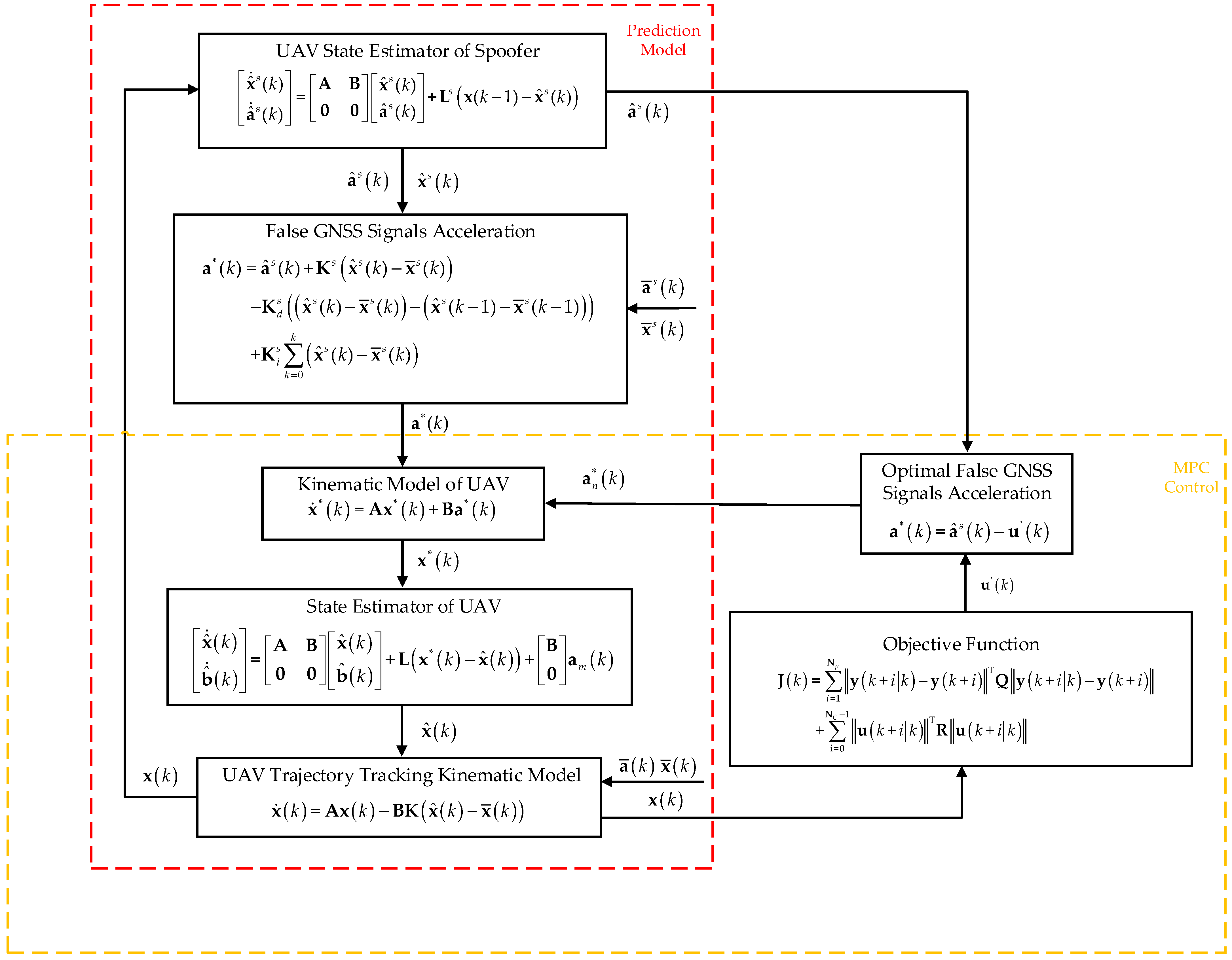
MPC is an advanced control strategy that uses a mathematical model of a dynamic system to predict its future behavior over a specified time horizon. It optimizes the control inputs at each time step by solving a constrained optimization problem, thereby allowing for ratified control actions that achieve desired performance while adhering to system constraints [43,44,45,46]. By deriving optimal control inputs based on these predictions, MPC facilitates optimal system control. Widely utilized in industrial automation, robotics control, and intelligent transportation, MPC provides a structured approach to control methodology that can be integrated into the steps of spoofing. The detailed framework of the proposed dynamic trajectory spoofing method is illustrated in Figure 2. It can be noticed that the framework is composed of two primary components: the prediction model and the MPC control model. The mutual composition of these two components is the UAV’s trajectory tracking control model, which plays a crucial role in the method. The inputs of the method include several key components. First, there is the predetermined reference trajectory of the UAV. This trajectory serves as the target path for the UAV. Second, the preset spoofing trajectory is generated by the spoofer. This trajectory is intended to mislead the UAV’s navigation system. Finally, the initial state x ( 0 ) of the UAV is also included as an input.
The procedure of the method can be summarized as follows. The spoofer uses the UAV state information acquired from external sensors, and the current UAV state x ( k ) to estimate the current state quantity x ^ s ( k ) and acceleration a ^ s ( k ) of the UAV. Then, the spoofer calculates the possible control input using proportional, integral and differential state information. Based on the aforementioned steps, the MPC control loop calculates the control effects of the possible control input and determines the optimal one by minimizing the objective function. The optimal u ( k ) is used to obtain the acceleration quantity a n * ( k ) , corresponding to the new false satellite signal to the UAV trajectory tracking model.
For a linear system of general form
{ x ˙ = A m x + B m u y = C m x ,
where x is system state vector, A m is state matrix, B m is input matrix, u is system input, y is system output, and C m is output matrix.
To fit with the UAV spoofing model, Equation (12) is discretized to obtain
{ x ( k + 1 ) = A d x ( k ) + B d u ( k )   y ( k ) = C d x ( k ) ,
where d indicates that the coefficient matrices are corresponding to those of Equation (12) in the discrete state.
With the UAV spoofing control model, we can predict the value of the future state of the UAV, denoted as
x ( k + i | k ) ,   i = 1 , , N p .
Substituting Equation (14) into Equation (13) yields the prediction output as
[ y ( k + 1 | k ) y ( k + 2 | k ) y ( k + N p | k ) ] = [ C d 0 0 0 C d 0 0 0 C d ] [ x ( k + 1 | k ) x ( k + 2 | k ) x ( k + N p | k ) ] .
To enhance the effectiveness of spoofing by utilizing future state information, the objective function is formulated as follows:
J ( k ) = i = 1 N p y ( k + i | k ) y ( k + i ) T Q y ( k + i | k ) y ( k + i ) + i = 0 N C - 1 u ( k + i | k ) T R u ( k + i | k ) ,
where Q is the error weighting matrix, and R is the control incremental weighting matrix. The optimal control input u ( k ) for the spoofing control model is the one that minimizes the objective function.
The prediction model used in MPC encompasses the complete UAV spoofing control model, which integrates both the UAV spoofing control model and the trajectory control model. Furthermore, the trajectory spoofing control model adheres to the double-integrator kinematics equation, with its initial state aligned with the UAV’s predetermined path:
x ¯ ˙ s ( k ) = A x ¯ s ( k ) + B a ¯ s ( k ) ,
where x ¯ s is the state of the spoofing trajectory at time instance k , and a ¯ s ( k ) is the acceleration of the spoofing trajectory.
In order to measure the actual state of the target UAV, external devices such as electrooptic sensors or radar can be employed to acquire the state x ^ s ( k ) and acceleration a ^ s ( k ) information. The target UAV is non-cooperative, and the sensor measurements are influenced by various factors. These factors include device resolution and environmental uncertainties. As a result, the acquired data may contain noise. Therefore, these data cannot be used directly. Hence, a linear estimator is employed to model the UAV state estimation process using the information obtained from external sensors, as outlined below:
[ x ^ ˙ s ( k ) a ^ ˙ s ( k ) ] = [ A B 0 0 ] [ x ^ s ( k ) a ^ s ( k ) ] + L s ( x ( k 1 ) x ^ s ( k ) ) ,
where the composition of L s resembles that of L .
The acceleration of the spoofing signal is derived by comparing the spoofer’s desired UAV state with the state estimated by the spoofer:
a * ( k ) = a ^ s ( k ) + K s ( x ^ s ( k ) x ¯ s ( k ) ) K d s ( ( x ^ s ( k ) x ¯ s ( k ) ) ( x ^ s ( k 1 ) x ¯ s ( k 1 ) ) ) + K i s k = 0 k ( x ^ s ( k ) x ¯ s ( k ) ) ,
where K s , K d s , K i s signify the spoofing controller parameters. The input is then substituted with u ( k ) which minimizes the objective function.
a * ( k ) = a ^ s ( k ) u ( k )
The acceleration, velocity, and position features of the spoofing signals also conform to the double-integrator kinematic model:
x ˙ * ( k ) = A x * ( k ) + B a * ( k ) .
It can be noticed that a * ( k ) is designed as a PID controller. The procedure for calculating the optimal spoofing control input is as follows:
(1)
Estimate the system state x ( k ) at time instance k ;
(2)
Use the input u ( k ) ,   u ( k + 1 ) , , u ( k + N C 1 ) to calculate the system output y ( k ) ,   y ( k + 1 ) , , y ( k + N p ) based on the spoofing model and the objective function (16). Here N C is the control horizon and N p is the prediction horizon;
(3)
Substitute the input and output into the objective function to determine the optimal input, and use the optimal input as the current time instance input in the spoofing model;
(4)
Return to step (2) and continue the calculations from the subsequent time instance, and apply the aforementioned steps repeatedly until the end of the spoofing operation.
Thus, by generating a spoofing signal with dynamics depicted a * ( k ) , and replacing the real satellite signal in the UAV trajectory tracking control model with such spoofing signal, the dynamic trajectory of the UAV can be manipulated in a covert manner. As for the spoofing signal generation, literature such as [18,19] already provided some suitable SDR platforms. It is worth noting that the requirements for dynamic trajectory spoofing are much stricter than those for point spoofing or time spoofing, since the spoofing signal featuring dynamics is changing more frequently and needs timely adjustment based on the closed-loop responses of the UAV target throughout the entire spoofing operation. The state information of non-cooperative UAVs must be fed into the control loop in real time from external sensors. Additionally, the optimal model control input and the corresponding parameters for spoofing signal generation must be calculated within the control intervals to avoid unnecessary control delays.
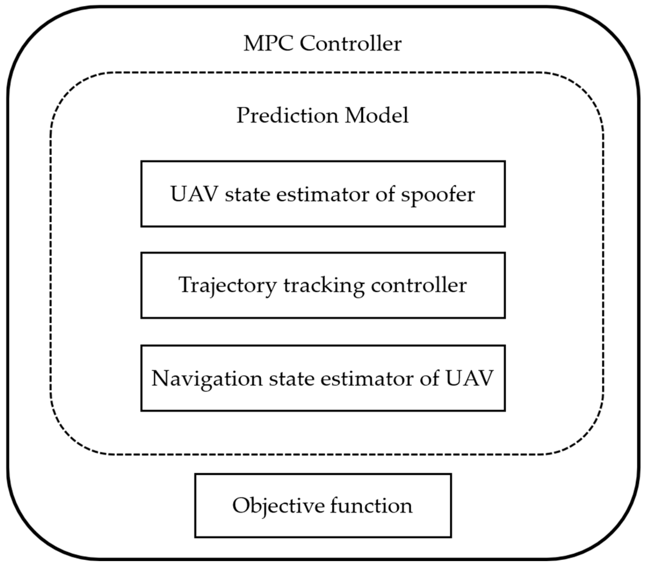
A block diagram of the MPC-based UAV dynamic trajectory spoofing controller is shown in Figure 3. The method consists of two parts: the prediction model and the objective function. The prediction model includes the UAV state estimator of the spoofer, trajectory tracking controller and navigation state estimator of the UAV. The dynamic trajectory spoofing algorithm procedure is shown in Algorithm 1.
Algorithm 1. MPC-based UAV dynamic trajectory spoofing algorithm procedure
Input: Reference trajectory, spoofing trajectory
1: Initialization: x = 0
2: for k = 1 until meeting terminal condition
3:   Use state estimator of spoofer to get UAV state x ^ s ( k )
4:   Acquire a s ( k ) with x ^ s ( k ) and spoofing trajectory
5:   Calculate a * ( k ) with Equation (19)
6:   Substitute a * ( k ) into the double-integrator kinematic model to get x * ( k )
7:   Use state estimator of UAV to get x ^ ( k )
8:   Calculate UAV actual state x ( k ) with Equations (1) and (11)
9:   Calculate the output y ( k ) with x ( k )
10:   Substitute input and output to objective function
11:   if a n s ( k ) minimizes objective function
12:    Update input a s ( k ) with a n s ( k )
13:    Substitute a n s ( k ) to step 5 to 9
14:   end if
15:   Update: Set k = k + 1
16: end for
Output: x ( k )

4. Simulation Verification and Discussion

To quantitatively evaluate the spoofing effectiveness of the proposed method, two distinct dynamic reference trajectory scenarios, a triangular trajectory and a square one, have been considered, respectively.
  • Experiment 1: Triangular Reference Trajectory (see Figure 4).
The first side and fourth side of the trajectory are set as
a ¯ x = { 0.1 ,   0 t < 20 ,   270 t < 290 0 ,   20 t < 70 ,   290 t < 340 0.1 ,   70 t < 90 ,   340 t < 360 , a ¯ y = { 0.1 ,   0 t < 20 ,   270 t < 290 0 ,   20 t < 70 ,   290 t < 340 0.1 ,   70 t < 90 ,   340 t < 360 .
The second side and fifth side are set as
a ¯ x = { 0.1 ,   90 t < 110 ,   360 t < 380 0 ,   110 t < 160 ,   380 t < 430 0.1 ,   160 t < 180 ,   430 t < 450 ,
a ¯ y = { 0.1 ,   90 t < 110 ,   360 t < 380 0 ,   110 t < 160 ,   380 t < 430 0.1 ,   160 t < 180 ,   430 t < 450 .
The third side and sixth side are set as
a ¯ x = { 0.2 ,   180 t < 200 ,   450 t < 470 0 ,   200 t < 250 ,   470 t < 520 0.2 ,   250 t < 270 ,   520 t < 540 ,
a ¯ y = 0 ,   180 t < 270 ,   450 t < 540 .
The spoofing target trajectory is a straight line,
a ¯ x s = 0.002 ,   a ¯ y s = 0.002 .
To compare the performance of the proposed method with that of the existing one, the control parameters are set the same with those in [36]:
K = [ 1 1 2 2 0.1 1 1 2 ] ,
K s = [ 0.01 0 0.1 0 0 0.01 0 0.1 ] .
The control gains for the derivative and integral components are set as
K d s = [ 0.2 0 0.2 0 0 0.2 0 0.2 ] ,
K i s = [ 0.01 0 0.003 0 0 0.01 0 0.003 ] .
The gain matrices can be obtained by solving the Riccati Equation (4) as
L = [ 0.1322 0 0.5270 0 0 0.1322 0 0.5270 0.0119 0 0.1470 0 0 0.0119 0 0.1470 0.0293 × 10 4 0 0.3642 × 10 4 0 0 0.0293 × 10 4 0 0.3642 × 10 4 ] ,
L s = [ 0.1500 0 0.9885 0 0 0.1500 0 0.9885 0.0222 0 1.8197 0 0 0.0222 0 1.8197 0.0029 0 1.6666 0 0 0.0029 0 1.6666 ] .
The value of A m varies over time, and A m at each moment can be calculated by solving the entire MPC-based UAV spoofing control model. The output matrix is set as the identity matrix for simplicity:
C d = [ 1 0 0 0 0 1 0 0 0 0 1 0 0 0 0 1 ] .
Figure 3 shows the dynamic trajectory spoofing effect of the UAV. It can be seen that the reference trajectory is represented as a triangle (the black line), and the spoofing trajectory set by the spoofer is a straight line (the yellow line). The actual trajectory of the UAV (the blue line) follows the spoofing trajectory. The black arrow represents the direction of movement of the UAV. The two trajectories do not coincide exactly due to control errors. By providing the UAV with false spoofing signals with kinematics calculated by the spoofer’s model, we can lead the UAV’s state estimator to believe that its trajectory closely resembles the reference trajectory, despite the fact that it does not. The estimated trajectory by the UAV is shown in the figure as the red dashed line.
The experiment settings in this study differ slightly from those described in [36] in terms of the spoofing operation durations. Specifically, the duration employed in this research is twice that reported in the literature, allowing for a more intuitive demonstration of the spoofing control effect. In order to analyze the effects of spoofing quantitatively, the root mean square errors (RMSEs) of position and velocity between the reference trajectory and the actual trajectory of the UAV are utilized as the evaluation metrics:
RMSE r = ( r x r ¯ x s ) 2 + ( r y r ¯ y s ) 2 ,
RMSE v = ( v x v ¯ x s ) 2 + ( v y v ¯ y s ) 2 .
Figure 4. Dynamic trajectory spoofing effect with triangular reference trajectory.
Drones 08 00602 g004
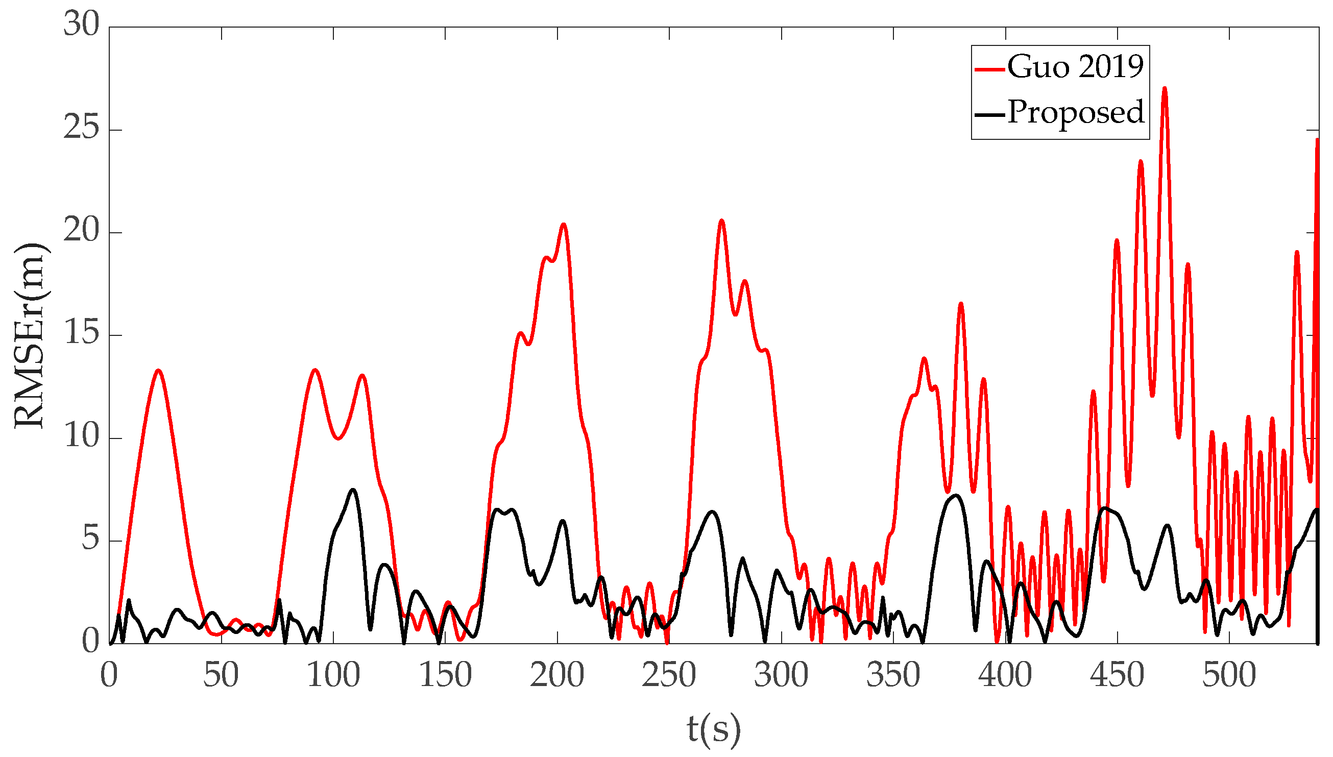
As illustrated in Figure 5, there is a notable trajectory spoofing effect enhancement compared to the spoofing method referenced in [36], especially during time intervals such as 70~120 s and 170~210 s. A review of the predefined trajectory configuration indicates that these intervals coincide with abrupt changes in acceleration and sudden changes in the target UAV’s trajectory. Existing methods such as the one presented in [36] exhibit fast rising spoofing control errors. In contrast, the method proposed in this paper demonstrates a considerable error reduction. This improvement can be attributed to the utilization of a differential approach, enhancing the tracking speed of the spoofer’s trajectory. Furthermore, the MPC algorithm anticipates future changes and adjusts control inputs in response to significant errors, thereby contributing to the observed spoofing performance enhancement.
Figure 6 shows the velocity tracking RMSE of the two spoofing methods. It can be noticed that there is a significant increase in spoofing errors over time with the method presented by [36], indicating a substantial cumulative effect. In contrast, the method introduced in this paper effectively mitigates the cumulative errors, which makes the spoofing more accurate and covert. This enhancement is attributed to calculating the optimal control input based on the error integration information and the preceding time instances control effect.
To conduct a comprehensive assessment of the proposed method, we calculated and compared the maximum and mean errors across the spoofing operation, and compared the results of the method proposed in this paper with those of the method in [36]. As shown in Table 1, the result reveals a substantial spoofing performance improvement with the proposed method, demonstrating a 67.48% reduction in terms of the mean value of RMSEr, and a 69.79% decrease in the mean value of RMSEv, compared with the results of the proposed method in [36].
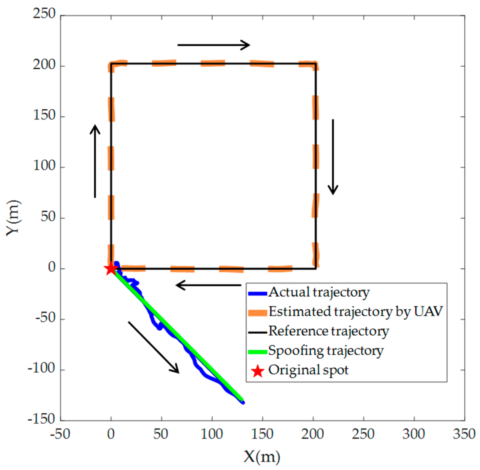
In order to verify the spoofing effectiveness and adaptability of the proposed method in various scenarios, the reference trajectory is defined as a square trajectory, while the other conditions remain unchanged.
  • Experiment 2: Square Reference Trajectory (see Figure 7).
The first side of the reference trajectory is set as follows:
a ¯ x = { 0 ,   0 t < 45 0 ,   45 t < 90 ,
a ¯ y = { 0.1 ,   0 t < 45 0.1 ,   45 t < 90 .
The second side:
a ¯ x = { 0.1 ,   90 t < 135 0.1 ,   135 t < 180 ,
a ¯ y = { 0 ,   90 t < 135 0 ,   135 t < 180 .
The third side:
a ¯ x = { 0 ,   180 t < 225 0 ,   225 t < 270 ,
a ¯ y = { 0.1 ,   180 t < 225 0.1 ,   225 t < 270
The fourth side:
a ¯ x = { 0.1 ,   270 t < 315 0.1 ,   315 t < 360
a ¯ y = { 0 ,   270 t < 315 0.1 ,   315 t < 360 .
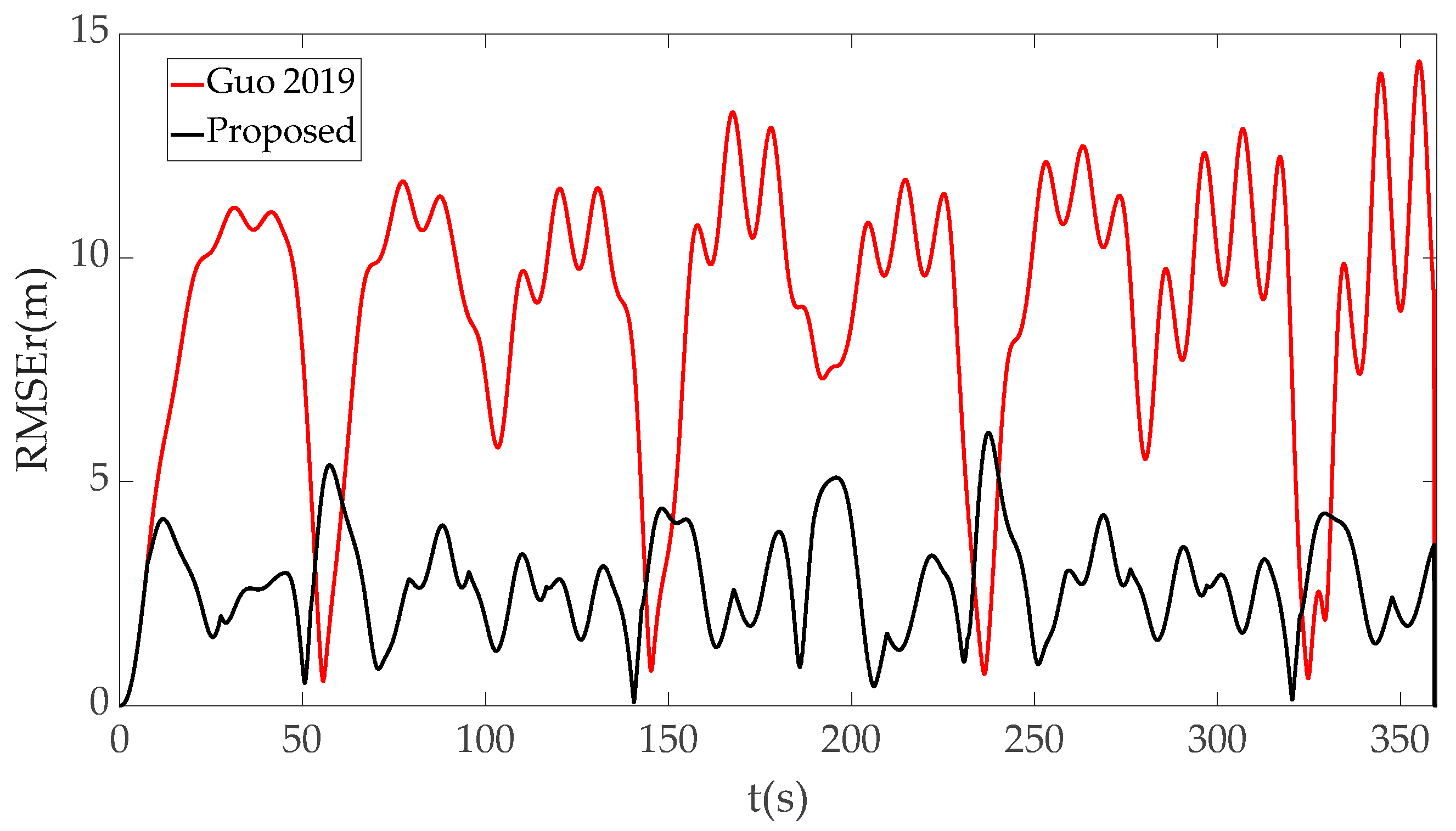
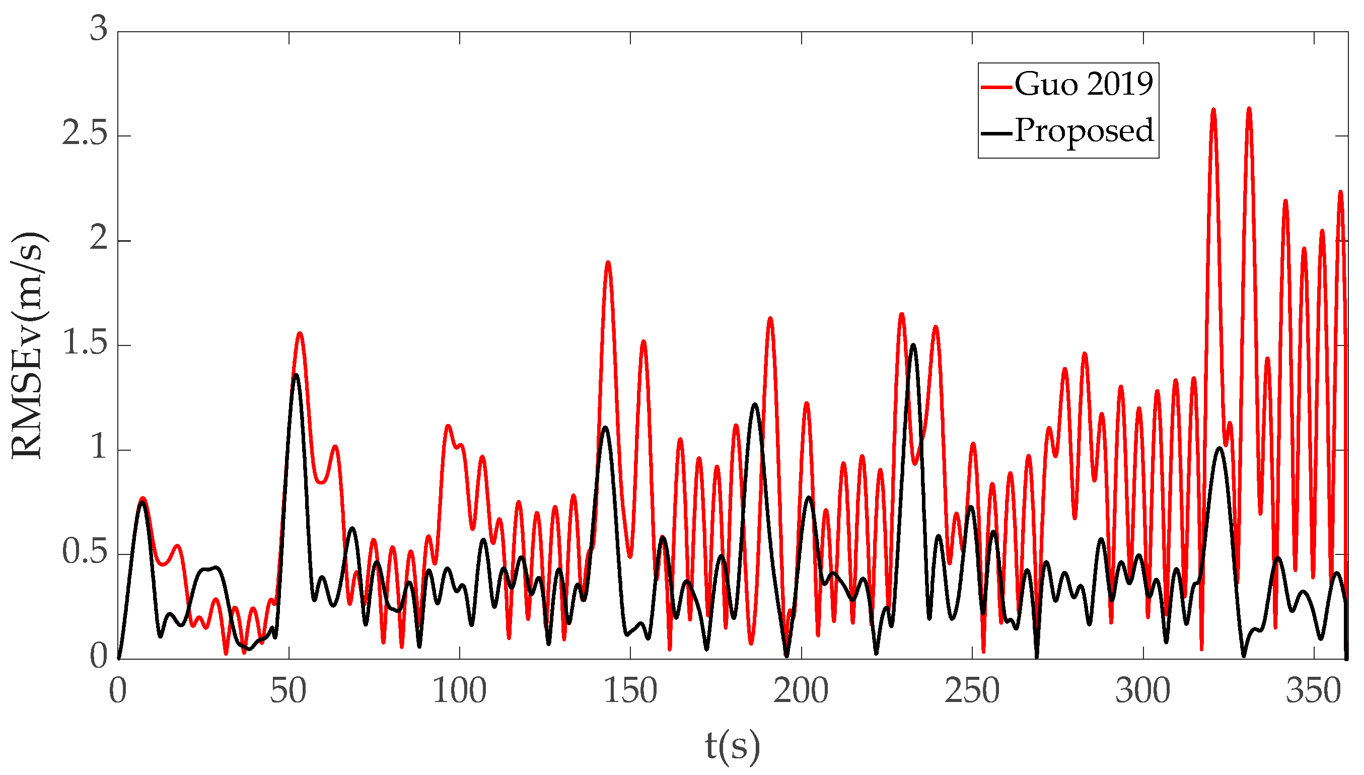
The dynamic trajectory spoofing effect with square reference trajectory is shown in Figure 7. As illustrated in Figure 8 and Figure 9, the proposed spoofing method exhibited significant reductions in both the RMSEr and RMSEv values compared with the method in [36], demonstrating that high-quality spoofing performance can also be achieved with the square reference trajectory. From the statistical data presented in Table 2, it can be noticed that the proposed spoofing method outperformed the method in [36], reducing the mean RMSEr and mean RMSEv values by 69.46% and 49.06%, respectively, across the entire spoofing operation. A substantial enhancement in both position and velocity spoofing accuracy has been achieved for the UAV’s dynamic trajectory control by implementing the proposed method.
Figure 7. Dynamic trajectory spoofing effect with square reference trajectory.
Drones 08 00602 g007
With the results of the two aforementioned experiments and the accompanying analysis, it can be seen that the proposed spoofing method demonstrated superior effectiveness compared to the existing method in both the dynamic trajectory control accuracy and control response timeliness. It is worth noting that the control gain matrices such as K s , K d s and K i s are set as constants in the two experiments. By optimizing these control parameters, the spoofing performance can be further enhanced.

5. Conclusions

The dynamic trajectory spoofing problem for UAVs has been investigated in this paper. To address challenges such as significant spoofing errors during rapid acceleration changes and the accumulation of errors over time in existing methods, a spoofing method based on MPC with superior performance has been proposed. The details of the spoofing procedure have been provided. Results from the simulation experiments demonstrate a substantial enhancement in trajectory control accuracy and a reduction in cumulative errors. The proposed method makes spoofing detection more difficult and the spoofing operation more covert, which paves the way for successful dynamic trajectory spoofing of UAVs. For future studies, it is important to acknowledge that verifying the effectiveness of spoofing through numerical simulations may be insufficient. Developing a comprehensive closed-loop control system for field experiments on spoofing requires significant effort, but such endeavors are likely to yield more valuable insights. An alternative validation method involves using software-in-the-loop (SITL) simulation, such as ArduPilot. It also should be noted that the UAV dynamics in this paper are modeled as double-integrator. Although this model adequately describes UAV movement characteristics in most scenarios, it may not demonstrate optimal performance under conditions such as wind or sudden unstable movements. Implementing spoofing in such non-ideal conditions presents additional challenges. The dynamic models utilized by some UAVs and the SITL environment may differ significantly from the one used in this paper, which could hinder the performance of the proposed method. One potential solution to this issue is to employ advanced control technologies, such as reinforcement learning, instead of traditional methods. As UAV anti-spoofing capabilities continue to advance with emerging technologies like array antennas and integrated visual-inertial navigation systems, the challenge of spoofing and gaining control over these UAVs remains an unresolved issue that warrants further investigation.

Author Contributions

Conceptualization, B.H.; methodology, B.H.; validation, Z.Y., B.H. and Z.F.; software, Z.Y.; resources, H.W. and B.H.; formal analysis, Z.Y. and B.H.; investigation, Z.Y. and X.J.; data curation, Z.Y.; writing—original draft preparation, B.H and Z.Y.; writing—review and editing, B.H. and Z.Y.; visualization, X.J.; supervision, B.H.; project administration, B.H. and H.W.; funding acquisition, B.H. and H.W. All authors have read and agreed to the published version of the manuscript.

Funding

This research was supported in part by National Natural Science Foundation of China Youth Program, grant number 62003363 and 62303485, Shaanxi Province Natural Science Basic Research Program, grant number 2022KJXX-99, and Defense Industrial Technology Development Program, grant number JCKY2021912B001.

Data Availability Statement

Data are contained within the article.

Conflicts of Interest

The authors declare no conflicts of interest.

Abbreviations

The following abbreviations are used in this manuscript:
UAVUnmanned aircraft vehicle
MPCModel predictive control
GNSSGlobal navigation satellite system
INSInertial navigation system
IMUInertial measurement unit
SDRSoftware-defined radio

References

  1. Muchiri, G.; Kimathi, S. A review of applications and potential applications of UAV. In Proceedings of the Sustainable Research and Innovation Conference, Riyadh, Saudi Arabia, 19–22 February 2022; pp. 280–283. [Google Scholar]
  2. Tsouros, D.; Bibi, S.; Sarigiannidis, P. A review on UAV-based applications for precision agriculture. Information 2019, 11, 349. [Google Scholar] [CrossRef]
  3. Fan, B.; Li, Y.; Zhang, R. Review on the technological development and application of UAV systems. Chin. J. Electron. 2020, 29, 199–207. [Google Scholar] [CrossRef]
  4. Perikleous, D.; Koustas, G.; Velanas, S.; Margariti, K.; Velanas, P.; Gonzalez-Aguilera, D. A novel drone design based on a reconfigurable unmanned aerial vehicle for wildfire management. Drones 2024, 8, 203. [Google Scholar] [CrossRef]
  5. Kovács, B.; Vörös, F.; Vas, T.; Károly, K.; Gajdos, M.; Varga, Z. Safety and security-specific application of multiple drone sensors at movement areas of an aerodrome. Drones 2024, 8, 231. [Google Scholar] [CrossRef]
  6. Novák, A.; Kováčiková, K.; Kandera, B.; Sedláčková, A.N. Global navigation satellite systems signal vulnerabilities in unmanned aerial vehicle operations: Impact of affordable software-defined radio. Drones 2024, 8, 109. [Google Scholar] [CrossRef]
  7. Mugnai, M.; Teppati Losé, M.; Herrera-Alarcón, E.; Baris, G.; Satler, M.; Avizzano, C. An efficient framework for autonomous UAV missions in partially-unknown GNSS-denied environments. Drones 2023, 7, 471. [Google Scholar] [CrossRef]
  8. Lemieszewski, Ł.; Prochacki, S. Decision support for autonomous drone flight based on satellite navigation signal. Procedia Comput. Sci. 2023, 225, 1691–1698. [Google Scholar] [CrossRef]
  9. Zhang, R.; Hao, G.; Zhang, K. Unmanned aerial vehicle navigation in underground structure inspection: A review. Geol. J. 2023, 58, 2454–2472. [Google Scholar] [CrossRef]
  10. Lemieszewski, Ł.; Borkowski, P.; Radomska-Zalas, A.; Dobryakova, L.; Ochin, E. Cybersecurity of the Unmanned Marine Vehicles in the Conditions of Partial or Complete Interruption Multi-GNSS Signals by Jamming and/or Spoofing. In Emerging Challenges in Intelligent Management Information Systems; Springer: Cham, Switzerland, 2024; pp. 83–94. [Google Scholar]
  11. Ochin, E.; Lemieszewski, A. Chapter 3—Security of GNSS. In GPS and GNSS Technology in Geosciences; Petropoulos, G.P., Srivastava, P.K., Eds.; Elsevier: Amsterdam, The Netherlands, 2021; pp. 51–74. [Google Scholar]
  12. Warner, J.; Johnston, R. A simple demonstration that the global positioning system (GPS) is vulnerable to spoofing. J. Secur. Adm. 2002, 25, 19–27. [Google Scholar]
  13. Warner, J.; Johnston, R. GPS spoofing countermeasures. Homel. Secur. J. 2003, 25, 19–27. [Google Scholar]
  14. Humphreys, T.; Ledvina, B.; Psiaki, M. Assessing the spoofing threat: Development of a portable GPS civilian spoofer. In Proceedings of the ION GNSS Conference, Savannah, GA, USA, 16–19 September 2008; pp. 2314–2325. [Google Scholar]
  15. Shepard, D.; Bhatti, J.; Humphreys, T. Evaluation of smart grid and civilian UAV vulnerability to GPS spoofing attacks. In Proceedings of the ION GNSS Conference, Nashville, TN, USA, 17–21 September 2012; pp. 3591–3605. [Google Scholar]
  16. Seo, S.; Lee, B.; Im, S.; Jee, G. Effect of spoofing on unmanned aerial vehicle using counterfeited GPS signal. J. Position. Navig. Timing 2015, 4, 57–65. [Google Scholar] [CrossRef]
  17. Norhashim, N.; Kamal, N.; Sahwee, Z.; Shah, S.; Sathyamoorthy, D.; Alfian, N. Effect of Global Navigation Satellite Signal (GNSS) spoofing on unmanned aerial vehicles (UAVs) via field measurement. In Proceedings of the IEEE 16th Malaysia International Conference on Communication (MICC), Kuala Lumpur, Malaysia, 10–12 December 2023; pp. 41–45. [Google Scholar]
  18. Feng, W.; Friedt, J.; Goavec-Merou, G.; Meyer, F. Software-defined radio implemented GPS spoofing and its computationally efficient detection and suppression. IEEE Aerosp. Electron. Syst. Mag. 2021, 36, 36–52. [Google Scholar] [CrossRef]
  19. Ferreira, R.; Gaspar, J.; Sebasti, A.; Souto, N. A software defined radio based anti-UAV mobile system with jamming and spoofing capabilities. Sensors 2022, 22, 1487. [Google Scholar] [CrossRef] [PubMed]
  20. He, D.; Qiao, Y.; Chen, S. A friendly and low-cost technique for capturing non-cooperative civilian unmanned aerial vehicles. IEEE Netw. 2019, 33, 146–151. [Google Scholar] [CrossRef]
  21. Chae, M.; Park, S.; Choi, S.; Choi, C. Commercial fixed-wing drone redirection system using GNSS deception. IEEE Trans. Aerosp. Electron. Syst. 2023, 59, 5699–5713. [Google Scholar] [CrossRef]
  22. Alharasees, O.; Abdalla, M.; Kale, U. Analysis of human factors analysis and classification system (HFACS) of UAV operators. In Proceedings of the New Trends in Aviation Development (NTAD), Novy Smokovec, Slovakia, 24–25 November 2022; pp. 10–14. [Google Scholar]
  23. Alharasees, O.; Adali, O.; Kale, U. Human factors in the age of autonomous UAVs: Impact of artificial intelligence on operator performance and safety. In Proceedings of the International Conference on Unmanned Aircraft Systems, Warsaw, Poland, 6–9 June 2023; pp. 798–805. [Google Scholar]
  24. Alharasees, O.; Adali, O.; Kale, U. UAV operators’ cognition and automation: Comprehensive measurements. In Proceedings of the New Trends in Aviation Development (NTAD), Stary Smokovec, Slovakia, 23–24 November 2023; pp. 15–20. [Google Scholar]
  25. Lee, Y.; Yeom, J.; Jung, B. A novel array antenna-based GNSS spoofing detection and mitigation technique. In Proceedings of the IEEE 20th Consumer Communications & Networking Conference, Las Vegas, NV, USA, 8–11 January 2023; pp. 489–492. [Google Scholar]
  26. Burbank, J.; Greene, T.; Kaabouch, N. Detecting and mitigating attacks on GPS devices. Sensors 2024, 24, 5529. [Google Scholar] [CrossRef]
  27. Nayfeh, M.; Li, Y.; Shamaileh, K.A.; Devabhaktuni, V.; Kaabouch, N. Machine learning modeling of GPS features with applications to UAV location spoofing detection and classification. Comput. Secur. 2023, 126, 103085. [Google Scholar] [CrossRef]
  28. Aissou, G.; Slimane, H.O.; Benouadah, S.; Kaabouch, N. Tree-based supervisedmachine learningmodels for detecting GPS spoofing attacks on UAS. In Proceedings of the IEEE 12th Annual Ubiquitous Computing, Electronics & Mobile Communication Conference (UEMCON), New York, NY, USA, 1–4 December 2021; pp. 0649–0653. [Google Scholar]
  29. Jiang, P.; Wu, H.; Xin, C. DeepPOSE: Detecting GPS spoofing attack via deep recurrent neural network. Digit. Commun. Netw. 2022, 8, 791–803. [Google Scholar] [CrossRef]
  30. Talaei Khoei, T.; Ismail, S.; Kaabouch, N. Dynamic selection techniques for detecting GPS spoofing attacks on UAVs. Sensors 2022, 22, 662. [Google Scholar] [CrossRef]
  31. Jayaweera, M. A novel deep learning GPS anti-spoofing system with DOA time-series estimation. In Proceedings of the 2021 IEEE Global Communications Conference (GLOBECOM), Madrid, Spain, 7–11 December 2021; pp. 1–6. [Google Scholar]
  32. Varshosaz, M.; Afary, A.; Mojaradi, B.; Saadatseresht, M.; Ghanbari Parmehr, E. Spoofing detection of civilian UAVs using visual odometry. ISPRS Int. J. Geo-Inf. 2020, 9, 6. [Google Scholar] [CrossRef]
  33. Finn, A.; Jia, M.; Li, Y.; Yuan, J. Detecting Stealthy GPS spoofing attack against uavs using onboard sensors. In Proceedings of the IEEE Conference on Computer Communications Workshops (INFOCOM WKSHPS), Vancouver, BC, Canada, 20–23 May 2024; pp. 1–6. [Google Scholar]
  34. Kerns, A.; Shepard, D.; Bhatti, J. Unmanned aircraft capture and control via GPS spoofing. J. Field Robot. 2014, 31, 617–636. [Google Scholar] [CrossRef]
  35. Guo, Y.; Wu, M.; Tang, K. Position deceptive tracking controller and parameters analysis via error characteristics for unmanned aerial vehicle. Int. J. Adv. Robot. Syst. 2018, 16, 172988141882540. [Google Scholar] [CrossRef]
  36. Guo, Y.; Wu, M.; Tang, K. Covert spoofing algorithm of UAV based on GPS/INS-integrated navigation. IEEE Trans. Veh. Technol. 2019, 68, 6557–6564. [Google Scholar] [CrossRef]
  37. Gao, Y.; LI, G. A GNSS instrumentation covert directional spoofing algorithm for UAV equipped with tightly-coupled GNSS/IMU. IEEE Trans. Instrum. Meas. 2023, 72, 99. [Google Scholar] [CrossRef]
  38. Geng, X.; Guo, Y.; Tang, K.; Wu, W.; Ren, Y. Research on covert directional spoofing method for INS/GNSS loosely integrated navigation. IEEE Trans. Veh. Technol 2023, 72, 5654–5663. [Google Scholar] [CrossRef]
  39. Dong, P.; Xiang, X.; Liang, Y. The research on channel estimation and signal-noise ratio estimation based on minimum error entropy Kalman filter for single carrier frequency domain equalization system. Int. J. Commun. Syst. 2023, 36, e5403. [Google Scholar] [CrossRef]
  40. Hu, G.; Xu, L.; Gao, B. Robust unscented Kalman filter-based decentralized multi sensor information fusion for INS/GNSS/CNS integration in hypersonic vehicle navigation. IEEE Trans. Instrum. Meas. 2023, 72, 1–11. [Google Scholar]
  41. Kiswanto, G.; Baskoro, A.; Hasymi, Z.; Ko, T. Tool wear monitoring in micro-milling based on digital twin technology with an extended Kalman filter. J. Manuf. Mater. Process 2024, 8, 108. [Google Scholar]
  42. Li, D.; Felix, J.; Chin, Y.; Jusuf, L.; Susanto, L. Integrated extended Kalman filter and deep learning platform for electric vehicle battery health prediction. Appl. Sci. 2024, 14, 4354. [Google Scholar] [CrossRef]
  43. Richalet, J.; Rault, A.; Testud, J. Model predictive heuristic control: Applications to industrial processes. Automatica 1978, 14, 413–428. [Google Scholar] [CrossRef]
  44. Yang, L.; Wang, X.; Zhou, Y.; Liu, Z.; Shen, L. Online predictive visual servo control for constrained target tracking of fixed-wing unmanned aerial vehicles. Drones 2024, 8, 136. [Google Scholar] [CrossRef]
  45. Wang, S.; Guo, J.; Mao, Y.; Wang, H.; Fan, J. Research on the model predictive trajectory tracking control of unmanned ground tracked vehicles. Drones 2023, 7, 496. [Google Scholar] [CrossRef]
  46. Li, B.; Song, C.; Bai, S.; Huang, J.; Ma, R.; Wan, K.; Neretin, E. Multi-UAV trajectory planning during cooperative tracking based on a fusion algorithm integrating MPC and standoff. Drones 2023, 7, 196. [Google Scholar] [CrossRef]
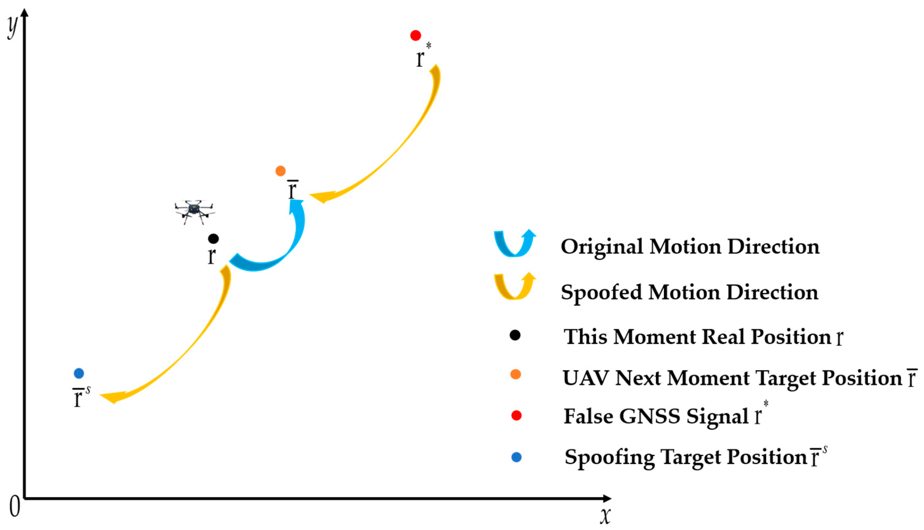
Figure 1. Schematic diagram of the spoofing principle.
Drones 08 00602 g001
Figure 2. MPC-based UAV dynamic trajectory spoofing control algorithm flow.
Drones 08 00602 g002
Figure 3. Block diagram of the MPC-based UAV dynamic trajectory spoofing controller.
Drones 08 00602 g003
Figure 5. RMSEr of [36] and the proposed method with triangular reference trajectory.
Drones 08 00602 g005
Figure 6. RMSEv of [36] and the proposed method with triangular reference trajectory.
Drones 08 00602 g006
Figure 8. RMSEr of [36] and the proposed method with square reference trajectory.
Drones 08 00602 g008
Figure 9. RMSEv of [36] and the proposed method with square reference trajectory.
Drones 08 00602 g009
Table 1. RMSE of [36] and the proposed method with triangular reference trajectory.
Spoofing MethodRMSEr MaxRMSEr MeanRMSEv MaxRMSEv Mean
Literature [36]27.04917.76197.88161.4832
Proposed7.50432.52411.56870.4481
Table 2. RMSE of [36] and the proposed method with square reference trajectory.
Spoofing MethodRMSEr MaxRMSEr MeanRMSEv MaxRMSEv Mean
Literature [36]14.38798.83672.63390.7807
Proposed6.09562.69851.50320.3977
Disclaimer/Publisher’s Note: The statements, opinions and data contained in all publications are solely those of the individual author(s) and contributor(s) and not of MDPI and/or the editor(s). MDPI and/or the editor(s) disclaim responsibility for any injury to people or property resulting from any ideas, methods, instructions or products referred to in the content.