Article

A Hierarchical Deep Reinforcement Learning Approach for Throughput Maximization in Reconfigurable Intelligent Surface-Aided Unmanned Aerial Vehicle–Integrated Sensing and Communication Network

by
Haitao Chen
,
Jiansong Miao
*,
Ruisong Wang
,
Hao Li
and
Xiaodan Zhang
Beijing Laboratory of Advanced Information Networks, Beijing University of Posts and Telecommunications, Beijing 100876, China
*
Author to whom correspondence should be addressed.
Drones 2024, 8(12), 717; https://doi.org/10.3390/drones8120717
Submission received: 18 October 2024 / Revised: 21 November 2024 / Accepted: 26 November 2024 / Published: 29 November 2024
(This article belongs to the Special Issue Space–Air–Ground Integrated Networks for 6G)

Abstract

:
Integrated sensing and communication (ISAC) is considered a key technology supporting Beyond-5G/6G (B5G/6G) networks, which allows the spectrum resources to be used for both sensing and communication. In this paper, we investigate an unmanned aerial vehicle (UAV)-enabled ISAC scenario, where the UAV sends ISAC signals to communicate with multiple users (UEs) and senses potential targets simultaneously, and a reconfigurable intelligent surface (RIS) is deployed to enhance the communication performance. Aiming at maximizing the sum-rate throughput of the system, we formulate the joint optimization problem of the trajectory and the beamforming matrix of the UAV, the passive beamforming matrix of the RIS. Currently, many researchers are working on using deep reinforcement learning (DRL) to address such problems due to its non-convex nature; however, as the environment becomes increasingly complex, high-dimensional state space and action space lead to a decrease in the performance of DRL. To tackle this issue, we propose a novel hierarchical deep reinforcement learning (HDRL) framework to solve the optimization problem. Through decomposing the original problem into the trajectory optimization problem and the sum-rate throughput optimization problem, we adopt a hierarchical twin-delayed deep deterministic policy gradient (HTD3) structure to optimize them alternately. The experimental results demonstrate that the obtained system sum-rate throughputs of the proposed HDRL with an HTD3 structure are 33%, 50%, and 10% higher than those obtained by TD3, twin-TD3 (TTD3), and TD3 with hovering only (TD3HO), respectively.

1. Introduction

With the emergence of various Beyond-5G(B5G)/6G concepts [1], numerous applications requiring sensing functionalities such as wireless localization, 4D imaging, autonomous driving, and activity sensing have aroused great interest in both academia and industry. Integrated sensing and communication (ISAC), which allows wireless devices to share spectrum resources for joint radar sensing and data communications, has been regarded as one of the key technologies to support B5G/6G networks [2]. ISAC provides significant advantages in many scenarios with high spectrum utilization efficiency. In addition, with the deployment of multiple-input-multiple-output (MIMO), which plays an important role in improving the performance of ISAC systems, ISAC networks could perform sensing and communication works synchronously with ultra-high sensing accuracy and communication performance [3]. However, the existence of severe channel degradation caused by complex environmental factors such as obstruction from trees and buildings results in unsatisfactory performance [4]. Thanks to the assistance of the reconfigurable intelligent surface (RIS), which adjusts the amplitude and phase shift of incident signals, the communication or sensing capabilities are significantly facilitated even when the direct path is blocked [5,6,7].
Unmanned aerial vehicles (UAVs) are regarded as a new type of aerial ISAC platform due to their flexibility and high line-of-sight (LoS) probability [8], whereas conventional terrestrial ISAC networks can only provide communication and sensing services within a limited distance, leading to a poor sensing performance. Many recent studies have demonstrated the superiority of UAV-ISAC systems (e.g., [2,9,10,11]). Lyu et al. [2] studied a UAV-enabled ISAC system and jointly optimized the beamforming matrix and trajectory of the UAV for the maximum average sum-rate throughput. Liu et al. [9] studied the joint optimization of task scheduling, transmit power allocation, and trajectory for maximum average sum-rate throughput of a UAV-aided ISAC system; notably, they considered 3D flight parameters to better utilize the flexibility of the UAV. Meng et al. [10] proposed a periodic ISAC system which is able to balance resources effectively in multi-user, multi-objective scenarios. Zhang et al. [11] studied a multi-UAV-assisted ISAC system; by utilizing the advantages of multi-UAVs, the performance of the UAV-ISAC system was further improved. Additionally, some studies have focused on secure transmission in UAV-ISAC networks (e.g., [12,13]). Wu et al. [12] utilized UAV-assisted ISAC to locate users and ensure secure transmission. Liu et al. [13] jointly optimized the scheduling policy, transmit power, and trajectory of the UAV to maximize the secure rate in the UAV-assisted ISAC system. Although these works provided outstanding results, the above studies still face many challenges; to be specific, most of them only considered ideal channel conditions (e.g., [2,9,10,12,13]), while imperfect channel conditions must be considered in specific UAV-ISAC applications. Moreover, the use of new technologies (e.g., RIS) provides further opportunities for improvement in the performance of UAV-ISAC systems, but many studies have not taken this into consideration.
RIS is a promising solution which can be used to enhance both communication and sensing, and improve channel quality affected by environmental factors. Some research studies have focused on RIS-aided UAV-ISAC networks (i.e., [14,15,16]). Yu et al. [16] studied the ISAC via RIS-UAV, where the UAV is not used as an ISAC platform, but rather as a carrier for RIS. Zhang et al. [15] investigated secure transmission for an RIS-aided UAV-ISAC network; they jointly designed the transmit power allocation, the scheduling policy, the passive beamforming matrix of RIS, and the trajectory and velocity of the UAV to maximize the average achievable rate (AAR). Wu et al. [16] jointly optimized the phase shift, the UAV’s trajectory, the beamforming matrix of the UAV, and the scheduling policy to maximize the weighted sum of average sum-rate and sensing signal-to-noise ratio (SNR). These studies have demonstrated the performance improvement of RIS on UAV-ISAC networks through reasonable comparison schemes. However, most works adopted convex optimization to solve approximate solutions to these problems, which may lead to local optimal solutions. On the one hand, such problems involve highly non-convex and intricate multi-variable coupling; on the other hand, channels affected by the environment are always time-varying, and traditional algorithms cannot adapt well to this characteristic. Hence, new approaches should be proposed to overcome the shortcomings of existing solutions.
Fortunately, the development of the deep learning field provides new solutions. Deep reinforcement learning (DRL), which combines deep neural networks (DNNs) and reinforcement learning (RL), is suitable for resolving the time-segmented tasks by abstracting them as a Markov decision process (MDP). DRL overcomes the complex time-varying characteristic of the environment, and has been widely used in research on UAVs [17,18,19,20,21]. Zhang et al. [17] proposed a safe deep Q-learning network (DQN) to ensure energy-efficient secure video streaming in UAV-enabled wireless networks. Miao et al. [18] applied deep deterministic policy gradient (DDPG) to optimize the energy efficiency of UAV-assisted mobile edge computing (MEC) video transmission. Yan et al. [19] combined long short-term memory (LSTM) with DDPG and jointly optimized the trajectory of the UAV and the task offloading strategy to minimize the system delay. Yao et al. [20] proposed a TD3 framework with Lyapunov optimization, which ensures the stability of the learning process in RIS-aided UAV networks. Wang et al. [21] proposed a TD3 approach for minimizing the completion time of data collection of UAV-based Internet of Things (IoT). These works provide sufficient conclusions and simulation results to demonstrate that DRL is an effective solution for solving UAV optimization problems. Other studies have focused on the application of DRL on optimization problems in ISAC (e.g., [22,23]). Liu et al. [22] proposed a DRL approach for an RIS-aided secure ISAC system; although they employed DRL in adjusting the transmit beamforming matrix and passive beamforming matrix of the RIS, they only considered the traditional ground ISAC scenario. Qin et al. [23] applied DRL to ISAC scenarios with multiple UAVs; nonetheless, they only considered the UAVs with a single antenna while ignoring the balance of communication and sensing resources. Generally speaking, few studies have considered a complete solution scheme of DRL applied to RIS-aided UAV-ISAC networks, which is a non-convex problem with high-dimensional state space and action space.
Even though DRL approaches have good adaptability to environments with high complexity, the use of DRL still faces challenges. On the one hand, normal DRL approaches suffer from inefficient exploration. On the other hand, large action space and state space may lead to low solving performance, and it is easy to fall into local optimal solutions [24]. Some studies improved the structure of DRL to alleviate these issues [25,26]. Tham et al. [25] proposed a twin-delayed deep deterministic policy gradient (TTD3) approach, where two agents are set to perform trajectory optimization and transmission performance optimization synchronously. Yang et al. [26] proposed a hybrid-proximal policy optimization (HPPO) approach to solve the optimization of mixed variables in UAV networks. These works adopted a parallel structure DRL; they first split the action space and state space, and then adopted multiple agents to solve the subproblems separately. However, such a structure ignores the correlation between the agents used to solve subproblems, leading to some limitations in solving performance. Fortunately, hierarchical deep reinforcement learning (HDRL), which decomposes the original problem into several subproblems, was proposed to resolve these problems. Not only can HDRL reduce the complexity of the problem but also it considers the correlation between hierarchical agents [27]. Susarla et al. [28] proposed a hierarchical deep Q-learning approach to consider mmWave beams with different beam width resolutions in a hierarchical manner in the beam pair alignment problem. Ren et al. [27] studied a UAV-assisted MEC scenario where the whole problem was decomposed into the location optimization problem and offloading optimization problem, and a hierarchical trajectory optimization and offloading optimization (HT3O) method was proposed to solve them alternately.
Although there are many studies focusing on UAV-ISAC networks, few studies have considered the RIS-aided UAV-ISAC networks and how to efficiently balance communication and sensing resources in such networks. Furthermore, there is still a lack of efficient DRL methods to solve such non-convex problems with high-dimensional state space and action space. Motivated by these challenges, we propose an RIS-aided UAV-ISAC system, where the UAV senses multiple potential targets and communicates with multiple users (UEs) synchronously within ISAC signals; the original problem is decomposed and solved with HDRL. Our detailed contributions can be listed as follows:
  • We investigate a RIS-aided UAV-ISAC system, where the UAV is equipped with the ISAC devices and sends ISAC signals, and an RIS is deployed to improve the link quality for better system performance. Subject to constraints on the maximum transmission power, maximum flight speed, and minimum sensing beampattern gain requirements, we jointly optimize the trajectory of the UAV, the beamforming matrix of the UAV, and the passive beamforming matrix of the RIS to maximize the sum-rate throughput of the system.
  • We transform the non-convex problem into a semi-Markov decision process (SMDP); the orignal problem is first decomposed into two subproblems, which are trajectory optimization and sum-rate throughput optimization. We then propose an HDRL framework with a hierarchical twin-delayed deep deterministic policy gradient (HTD3) structure for the joint optimization of the trajectory and beamforming matrix of the UAV as well as the passive beamforming matrix of the RIS.
  • We simulate the proposed algorithm and other benchmarks for comparison. Extensive results represent the effectiveness and superiority of the proposed HTD3. Specifically, we verify the convergence of the proposed algorithm via different environment parameters based on numerous experiments, and the experimental results demonstrate that HTD3 achieves a higher sum-rate throughput compared to other benchmarks.
The rest of the paper is organized as follows. Section 2 introduces the system model and formulates the sum-rate throughput optimization problem of the RIS-aided UAV-ISAC system. HDRL with an HTD3 structure is introduced in Section 3. Section 4 shows and analyzes the simulation results to represent the effectiveness and superiority of the proposed HTD3. The paper is concluded in Section 5.

2. System Model

2.1. System Overview

The model of the RIS-aided UAV-ISAC system is shown in Figure 1. One UAV with ISAC devices is deployed for synchronous radar sensing and transmission; to be specific, the UAV senses ground targets and synchronously sends the generated sensing data to UEs. Considering the obstruction of trees, buildings, and other obstacles, the channel between the UAV and UEs is the non-line-of-sight (NLOS). Moreover, the user’s location is far from the sensing area, and hence an RIS, which reflects the signals transmitted from the UAV and adjusts their electromagnetic wave characteristics, is adopted to enhance the performance of communication through improving the channel’s quality and the system’s performance. The sensing area contains J potential targets, which can be represented as a set J = { 1 , , J } . The ISAC devices in the UAV perform joint radar sensing and communication through sending combined communication and sensing signals. The set of UEs can be represented as K = { 1 , , K } . The UAV is equipped with an A-element uniform linear array (ULA) and the RIS is equipped with a uniform planar array (UPA) which consists of M passive reflecting elements. The finite ISAC mission duration is divided into N time slots, which can be denoted as N = { 1 , , N } . In each time slot, the UAV could move horizontally to adjust its position and perform sensing and communication synchronously.

2.2. Transmission Model

Let q u [ n ] = ( x u [ n ] , y u [ n ] , H ) denote the time-varying position of the UAV, where H is a fixed value representing the flight altitude. Let q k [ n ] = ( x k [ n ] , y k [ n ] , z k [ n ] ) , q R = ( x R , y R , z R ) denote the time-varying position of the k t h UE and the fixed position of the RIS, respectively; RIS is fixed on a building [20,25] and each UE randomly moves in a small area. Assuming that the duration of each time slot is δ f l y , the average flight speed of the UAV in the n t h time slot can be expressed as
v u [ n ] = | | q u [ n ] q u [ n 1 ] | | 2 δ f l y .
The channel from the UAV to the RIS can be regarded as an LoS link due to few obstacles, and hence the channel gain from the UAV to the RIS in time slot n can be expressed as
h U , R [ n ] = ρ 0 d U , R 2 [ n ] a p ( φ U , R [ n ] , θ U , R [ n ] ) a L H ( θ U , R [ n ] ) ,
where ρ 0 denotes the channel power gain at reference distance d 0 = 1 m , and d U , R [ n ] = | | q u [ n ] q R | | 2 denotes the distance between the UAV and the RIS in the n t h time slot. φ U , R [ n ] and θ U , R [ n ] denote the azimuth angle and the elevation angle of the RIS considering the position of the UAV. The steering vector of ULA and UPA can be calculated as:
a L ( θ ) = [ 1 , e j π cos ( θ ) , , e j π ( A 1 ) cos ( θ ) ] T ,
and
a P ( φ , θ ) = [ 1 , , e j π sin ( θ ) [ ( m 1 ) cos ( φ ) + ( a 1 ) sin ( φ ) ] , , e j π sin ( θ ) [ ( M 1 ) cos ( φ ) + ( A 1 ) sin ( φ ) ] ] T ,
respectively, where m { 1 , , M } , a { 1 , , A } .
For the channel from the UAV to UEs and from the RIS to UEs, the NLoS link is considered due to the obstruction of obstacles such as trees and buildings. A kind of probabilistic LoS channel is adopted [29], which can be expressed as
P L [ n ] = ( ϵ L o S ϵ N L o S ) 1 + a p l e b p l ( θ [ n ] a p l ) + 20 log 4 π f c d [ n ] v c + ϵ N L o S ,
where ϵ L o S , ϵ N L o S , and a p l , b p l denote the coefficients determined by the environment, and θ [ n ] denotes the elevation angle from the UEs to the UAV or RIS. Then, the channel from the UAV to the k t h UE and from the RIS to the k t h UE in time slot n can be expressed as
h U , k [ n ] = 10 P L U , k [ n ] 20 a L ( θ U , k [ n ] ) , k K ,
and
h R , k [ n ] = 10 P L R , k [ n ] 20 a P ( φ U , k [ n ] , θ U , k [ n ] ) , k K ,
respectively, and P L U , k [ n ] and P L R , k [ n ] can be expressed as
P L U , k [ n ] = ( ϵ L o S ϵ N L o S ) 1 + a p l e b p l ( θ U , k [ n ] a p l ) + 20 log 4 π f c d U , k [ n ] v c + ϵ N L o S ,
and
P L R , k [ n ] = ( ϵ L o S ϵ N L o S ) 1 + a p l e b p l ( θ R , k [ n ] a p l ) + 20 log 4 π f c d R , k [ n ] v c + ϵ N L o S ,
respectively, where d U , k [ n ] denotes the time-varying distance between the UAV and the k t h UE, d R , k [ n ] denotes the time-varying distance between the RIS and the k t h UE, θ U , k [ n ] denotes the time-varying elevation angle from the k t h UE to the UAV, and θ R , k [ n ] denotes the time-varying elevation angle from the k t h UE to the RIS. In particular, the cascaded channel gain from the UAV to the k t h UE in time slot n can be represented as
H U , k [ n ] = h U , k H [ n ] + h R , k H [ n ] Θ [ n ] h U , R [ n ] , k K ,
where Θ [ n ] denotes the passive beamforming matrix of RIS in time slot n, which can be expressed as Θ [ n ] = d i a g ( ξ 1 [ n ] e j ϕ 1 [ n ] , , ξ m [ n ] e j ϕ m [ n ] , , ξ M [ n ] e j ϕ M [ n ] ) , and ξ m [ n ] and ϕ m [ n ] are the amplitude coefficient and phase shift of the m t h RIS element, with ξ m [ n ] [ 0 , 1 ] and ϕ m [ n ] [ 0 , 2 π ] . To maximize the performance of RIS, we fix the ξ m [ n ] as 1.
Let s [ n ] = [ s 1 [ n ] , , s K [ n ] ] T C K × 1 with E [ | s k [ n ] | 2 ] = 1 denoting the transmitted symbol in time slot n, and s 0 [ n ] is a zero mean random vector with covariance matrix E [ s 0 [ n ] s 0 H [ n ] ] 0 denoting the dedicated radar sensing signal [2]. W [ n ] = [ w 1 [ n ] , , w K [ n ] ] C A × K denotes the beamforming matrix of the UAV, assuming that the communication signal could be used to facilitate sensing; the UAV transmits communication signals together with sensing signals, and hence the transmitted signal of the UAV in time slot n can be expressed as
x u [ n ] = W [ n ] s [ n ] + s 0 [ n ] ,
and overall, the received signal at the k t h UE can be expressed as
y k [ n ] = H U , k [ n ] x u [ n ] + z k [ n ] , k K ,
where z k [ n ] CN ( 0 , σ k 2 ) represents the Gaussian white noise.
For the k t h UE, interference comes from the undesired signal, sensing signal, and noise, and thus the received signal-to-interference-plus-noise ratio (SINR) at the k t h UE can be expressed as
S I N R k [ n ] = | H u , k [ n ] w k [ n ] | 2 k | H u , k [ n ] w k [ n ] | 2 + H u , k [ n ] E [ s 0 [ n ] s 0 H [ n ] H u , k H [ n ] + σ k 2 , k K , k K , k k ,
and then, the achievable rate of the k t h UE can be calculated by
r k [ n ] = l o g 2 ( 1 + S I N R k [ n ] ) , k K .

2.3. Sensing Model

The sensing performance can be described as the beam pattern gain of the radar towards the locations of the potential targets [2,10], and we assume that the communication signals are also used for sensing. The transmit beam pattern gain from the UAV to the j t h target with its location q j = ( x j , y j , z j ) can be given by
Γ ( q u [ n ] , q j ) = E [ | a L H ( θ U , j [ n ] ) x u [ n ] | 2 ] = a L H ( θ U , j [ n ] ) ( t r ( W u [ n ] W u H [ n ] ) + E [ s 0 [ n ] s 0 H [ n ] ) a L ( θ U , j [ n ] ) ,
where θ U , j [ n ] denotes the elevation from the j t h target to the UAV in time slot n; in this case, ISAC devices extract information from the reflected signals from the target, and its power is related to the distance between the UAV and the target. To ensure effective sensing, the beam pattern gain threshold Γ t h is set to represent the lowest sensing performance. Thus, the following constraint must be satisfied:
Γ ( q u [ n ] , q j ) d U , j 2 [ n ] Γ t h ,
where d U , j [ n ] denotes the distance between the UAV and the j t h target in time slot n. This constraint first ensures sufficient power allocation in the target direction to achieve successful sensing; then, considering that a larger beam pattern gain necessarily means better overall sensing performance, in this paper, this constraint is sufficient to represent sensing performance. In general, we maximize the communication performance of the system while satisfying this constraint.
UAVs extract sensing information from echo signals. Hence, we use average sensing SNR, which represents the quality of echo signals, to express the sensing performance throughout the entire transmission process. The average sensing SNR can be calculated by [30]
S N R s = 1 N n = 1 N j = 1 J s e ρ 0 2 Γ ( q u [ n ] , q j ) 16 π d U , j 4 [ n ] σ k 2 ,
where s e denotes the radar cross-section of the targets.

2.4. Problem Formulation

In the proposed RIS-aided UAV-ISAC system, we aim to optimize the accumulated sum-rate throughput of N time slots. The optimization is formulated as (P1):
(18a) ( P 1 ) : max Q , W [ n ] , Θ [ n ] , R s [ n ] 1 N n = 1 N k = 1 K r k [ n ] , (18b) s . t . t r ( W [ n ] W H [ n ] ) + t r ( R s [ n ] ) P max , n N , (18c) v u [ n ] v max , n N , (18d) Γ ( q u [ n ] , q j ) d U , j 2 [ n ] Γ t h , n N , (18e) ϕ m [ n ] [ 0 , 2 π ) , m 1 , , M , n N ,
where Q = { q u [ 1 ] , , q u [ N ] } denotes the trajectory of the UAV, R s [ n ] = E [ s 0 [ n ] s 0 H [ n ] ] denotes the covariance matrix of the sensing signal, Equation (18b) is the transmission power constraint, Equation (18c) indicates that the maximum UAV speed, Equation (18d) defines sensing threshold to ensure the sensing performance, and Equation (18e) defines a range of the phase shift of the RIS.

3. The Proposed Algorithm
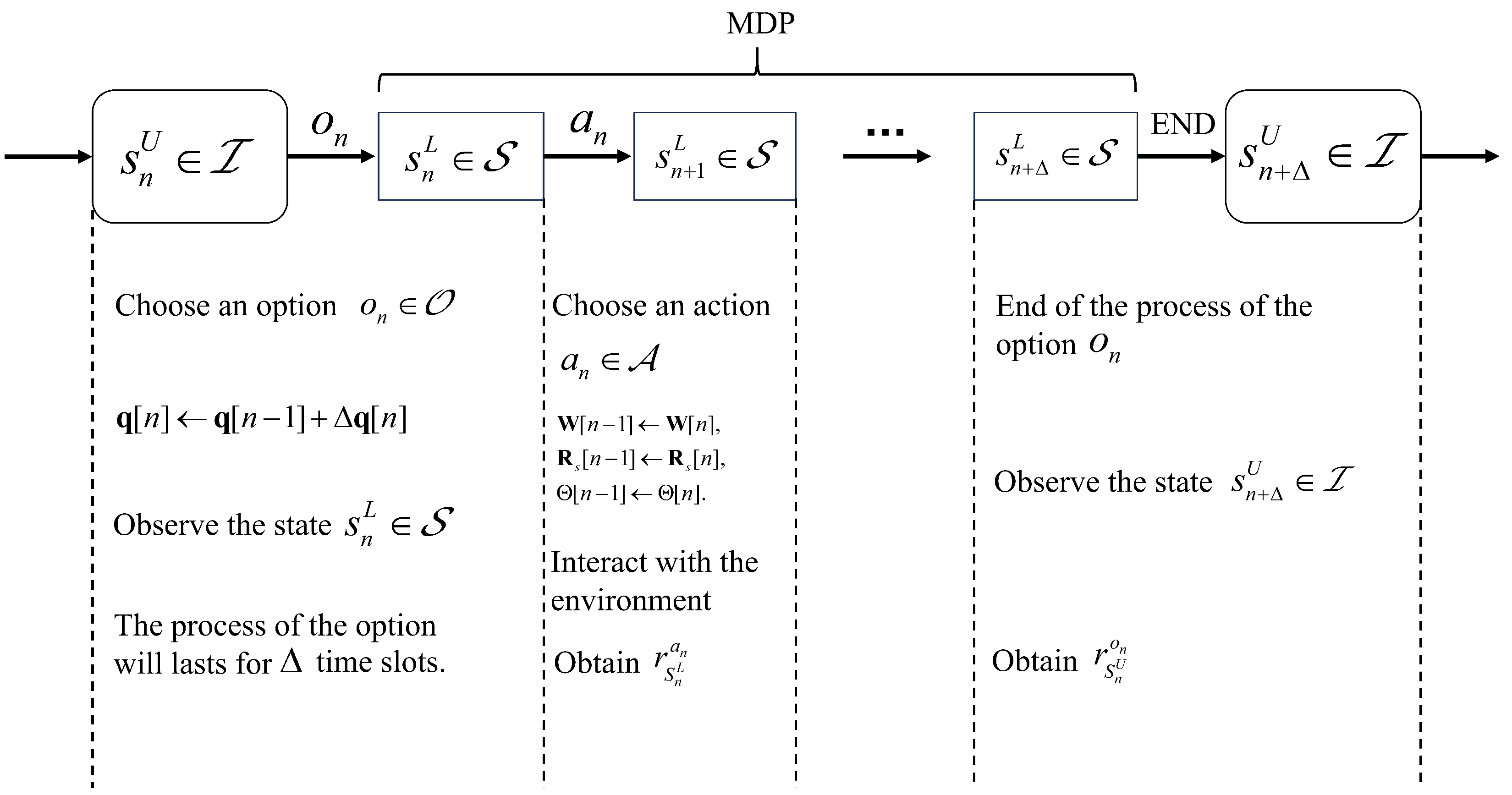
In this section, we propose an HTD3-structure HDRL framework for joint-trajectory beamforming optimization. The original problem is decomposed into two subquestions, which solve the trajectory optimization and beamforming task offloading optimization, respectively. The entire process is constructed as an SMDP, and the mechanism of our HTD3 is discussed.

3.1. SMDP

To reduce the dimension of action space and state space of the original problem, in this paper, the original problem can be decomposed into two parts, which are:
(19a) ( P ˜ 1 ) : max Q P ˜ 2 , (19b) s . t . v u [ n ] v max , n N ,
and
(20a) ( P ˜ 2 ) : max W [ n ] , Θ [ n ] , R s [ n ] 1 N n = 1 N k = 1 K r k [ n ] , (20b) s . t . t r ( W [ n ] W H [ n ] ) + t r ( R s [ n ] ) P max , n N , (20c) Γ ( q u [ n ] , q j ) d U , j 2 [ n ] Γ t h , n N , (20d) ϕ m [ n ] [ 0 , 2 π ) , m 1 , , M , n N .
These subproblems are regarded as a hierarchical structure. In the time slot n, we adjust the UAV’s location and for the next Δ time slots, we adjust the beamforming matrix, the sensing signal of the UAV, and the passive beamforming matrix of the RIS to perform sensing and communication. As shown in (19a) and (20a), we solve (20a) to achieve a higher sum-rate throughput, while we solve (19a) (i.e., adjust the UAV’s location) to maximize (20a).
The hierarchical structure mentioned earlier can be abstracted as an SMDP, and the UAV can be treated as an agent which executes options and actions. An SMDP consists of several MDPs, and each MDP starts from the agent’s option; an option set O is characterized by the state set I , the policy function π o , and the termination probability of an option β . In this article, the option o n O denotes the adjustment of the locations of the UAV (i.e., Δ q u [ n ] , the next location for the UAV to perform sensing and communication). We use M n = < S , A , R > to represent the MDP of the option, which denotes the process completing the sensing and communication tasks in the location chosen by option o n of the UAV. The details of the option set O can be described as follows:
(1)
State space  I : CSI is the most influential factor, which includes the estimated CSI between the UAV and the RIS, and between the UAV and the UEs. To evaluate the sensing performance, the distance between the UAV and the targets is also considered, and thus the state set of the options can be described as:
I = { d U , j [ n ] , h U , R [ n ] , h U , k [ n ] } , j J , k K .
(2)
Policy set  π o : π o denotes the policy set under an option o n ; since our option is the adjustment of locations of the UAV and we choose proper options to maximize ( P ˜ 2 ), the policy function can be described as the adjustment of the beamforming matrix, the sensing signal of the UAV, and the passive beamforming matrix of the RIS under the option o n , which are actions required to complete an option and can be described as:
π o = { W [ n ] , Θ [ n ] , R s [ n ] } .
(3)
Termination probability  β : β ( s n H ) denotes the termination probability at state s n H I . Each option o n denotes the location adjustment of the UAV in time slot n, and the UAV performs the sensing and communication tasks for the later Δ time slots; hence, β ( s n + Δ H ) = 1 means the termination probability of the option o n in the time slot n + Δ is 1, where s n + Δ H I denotes the state in time slot n + Δ .
Then, for a location chosen by the option o n , the UAV hovers to complete the sensing and communication in the later Δ time slots, which can be modeled as an MDP. The details of the MDP can be described as:
(1)
State space  S : The observed state consists of the location of the UAV, which is determined by the option o n , the estimated CSI between the UAV and the RIS, and between the UAV and the UEs, and the distance between the UAV and the targets; thus, the state space can be expressed as
S = { q u [ n ] , d U , j [ n ] , h U , R [ n ] , h U , k [ n ] } , j J , k K .
(2)
Action space  A : The action space contains the actions to perform the sensing and communication during the Δ time slots, which is consistent with the policy set π o , (i.e., Equation (22)).
(3)
Reward  R : Since our object is to maximize the sum-rate throughput during the whole N process, the sum-rate throughput within time slot n can be directly used as the reward, which can be expressed as
r s n L a n = P e , c o n s t r a i n t i s v i o l a t e d k = 1 K r k [ n ] , e l s e ,
where r s n L a n denotes the reward obtained by executing action a n A at the state s n L S , and P e denotes the penalty coefficient, which is set to 0 (i.e., no data transmission).
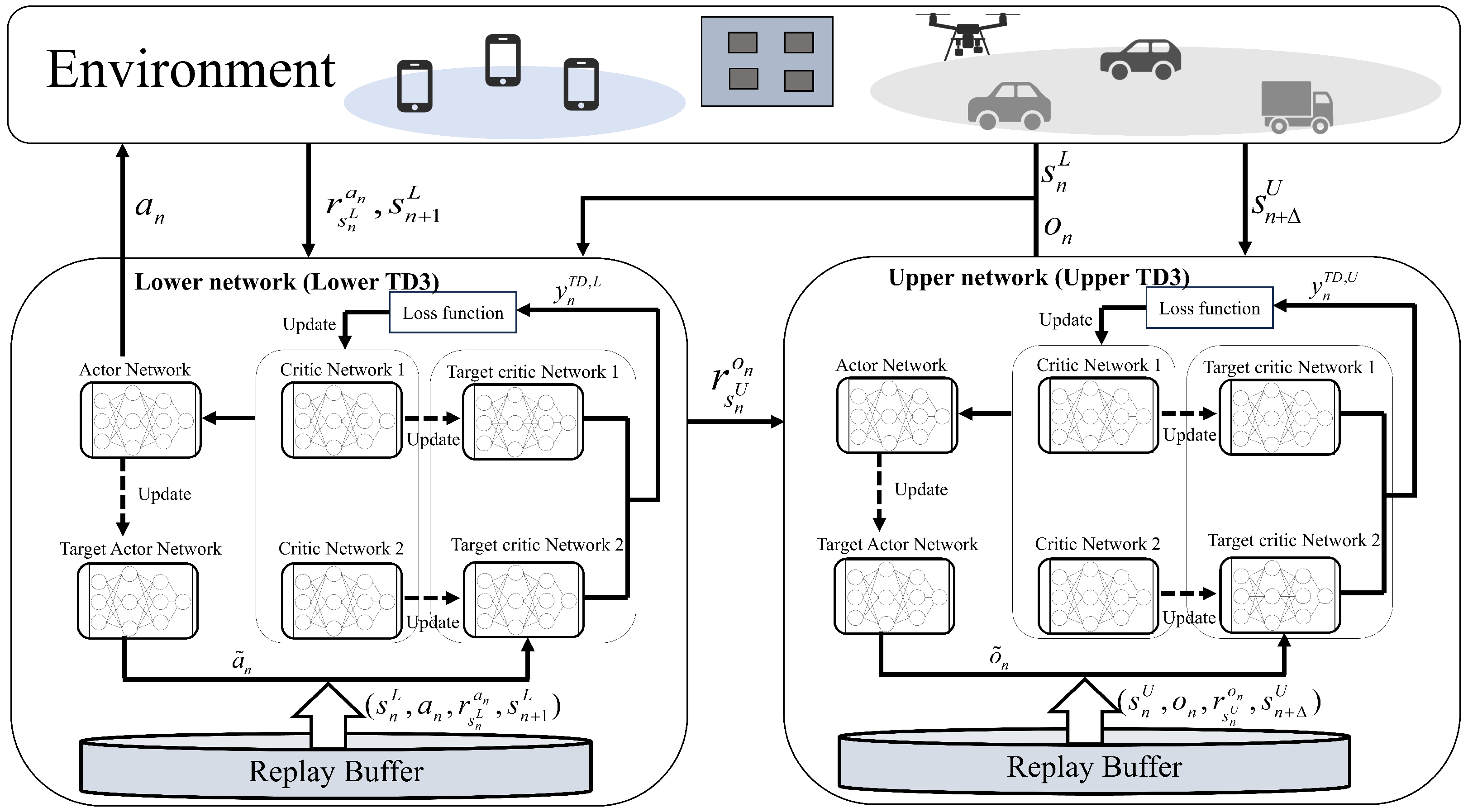
In summary, the process of the SMDP is shown in Figure 2. In time slot n, the state s n U is observed. An option o n is chosen to adjust the UAV’s location. The later Δ time slots can be regarded as an MDP. In each time slot, the UAV chooses an action a n to perform sensing and communication at the fixed location determined by the option o n . At the end of the process, we observe the state s n + Δ U at time slot n + Δ , obtain the reward r s n U o n for the option o n , and then start the next option selection.

3.2. HDRL Framework

The aforementioned SMDP can be solved with HDRL; hence, we design a two-layer HDRL to perform continuous action control, where the lower layer network is adopted to maximize the sum-rate throughput and the upper layer network is adopted to maximize the average reward of the lower layer network.
Similar to reward r s n L a n , the reward of executing option o n at state s n H can be expressed as
r s n U o n = E [ r s n + 1 L a n + 1 + γ r s n + 2 L a n + 2 + + γ Δ 1 r s n + Δ L a n + Δ | ε ( o n , s n U , n ) ] , s n U I , s n + 1 L , , s n + Δ L S ,
where ε ( o n , s n U , n ) denotes that option o n begins to be executed at time slot n and in state s n U . Thus, for option set O , the B e l l m a n equation is given by
Q O * ( s n U , o n ) = E [ r s n U o n + γ Δ max o O Q O * ( s n + Δ U , o ) | ε ( o n , s n U ) ] , s n U , s n + Δ U I , o n O ,
where Q O * ( s n U , o n ) denotes the optimal option-value function, and γ ( 0 , 1 ) denotes the discount factor, which represents the importance of the long-term return. And for MDP, the B e l l m a n equation can be given by
Q * ( s n L , a n ) = E [ r s n L a n + γ Δ max a A Q * ( s n + 1 L , a ) ] , s n L , s n + 1 L S , a n , a n + 1 A ;
if we use Q O ( s n U , o n ) and Q ( s n L , a n ) to represent the estimated optimal action-value function, then they can be updated by
Q O ( s n U , o n ) Q O ( s n U , o n ) + α [ r s n U o n + γ Δ max o O Q O * ( s n + Δ U , o ) Q O ( s n U , o n ) ] ,
and
Q ( s n L , a n ) Q ( s n L , a n ) + α [ r s n L a n + γ Δ max a A Q ( s n + 1 L , a ) Q ( s n L , a n ) ] ,
respectively, where α ( 0 , 1 ) denotes the learning rate.
The structure of the HDRL is an HTD3 structure, which is shown in Figure 3, where the upper network is adopted to solve (26), the lower network is adopted to solve (27), and both networks adopt a TD3 structure for continuous action control. The critic networks in the upper network can be expressed as Q ( s n U , o n , ϑ c , 1 U ) , Q ( s n U , o n , ϑ c , 2 U ) , which are adopted to estimate Q O * ( s n U , o n ) , where ϑ c , 1 U , ϑ c , 2 U are network parameters. The actor network in the upper network can be expressed as π ( s n , ϑ a U ) , which is adopted to estimate a r g m a x o O Q O * ( s n + Δ U , o ) . Similarly, the networks Q ( s n L , a n , ϑ c , 1 L ) , Q ( s n L , a n , ϑ c , 2 L ) and π ( s n , ϑ a L ) in the lower network are adopted to estimate Q * ( s n L , a n ) and a r g m a x a A Q * ( s n + 1 L , a ) , respectively.
The update process of HTD3 is divided into two parts, which are the storing experience and network updating. Let B U and B L denote the replay buffers of the upper network and the lower network, respectively. B U stores transitions ( s n U , o n , r s n U o n , s n + Δ U ) while B L stores transitions ( s n L , a n , r s n L a n , s n + 1 L ) , where o n and a n are, respectively, output by π ( s n , ϑ a U ) and π ( s n , ϑ a L ) . Then, the networks extract transitions from the replay buffer for training.
For the lower network, the objective of the critic networks is to estimate the action value as accurately as possible, and hence the TD target is adopted to represent the true value of the action value; with the transition ( s n L , a n , r s n L a n , s n + 1 L ) , the TD target can be calculated as
y n T D , L = r s n L + γ min i = 1 , 2 Q ( s n + 1 L , a ˜ n , ϑ ^ c , i L ) ,
where Q ( s n L , a n , ϑ ^ c , i L ) denotes the target network of the Q ( s n L , a n , ϑ c , i L ) . The minimum value of two target networks is adopted to avoid overestimation. Action a ˜ n denotes the action of the agent at state s n + 1 L , which can be calculated as
a ˜ n = π ( s n + 1 L , ϑ ^ a L ) + μ a ,
where μ a denotes the action noise with zero mean and variance σ a c t i o n 2 . Overall, the accuracy of the critic networks can be measured by the mean squared error (MSE) between the target value and the value estimated by the critic network, which can be expressed as
L ( ϑ c , i L ) = ( y n T D , L Q ( s n L , a n , ϑ c , i L ) 2 ) , i = 1 , 2 ,
and the critic networks can be updated by the gradient descent which can be expressed as
ϑ c , i L ϑ c , i L α c ϑ c , i L L ( ϑ c , i L ) , i = 1 , 2 ,
where α c denotes the learning rate of the critic networks. The objective of the actor network is to make the output value of the critic networks as large as possible, and hence the loss function of the actor network can be expressed as
L ( ϑ a L ) = 1 2 i Q ( s n L , π ( s n L , ϑ a L ) , ϑ c , i L ) , i = 1 , 2 .
Then, the actor network can be updated by the gradient ascent, which can be expressed as
ϑ a L ϑ a L + α a ϑ a L L ( ϑ a L ) .
In particular, the target networks of the critic networks and the actor networks can be soft-updated, respectively, by
(36a) ϑ c , i L ^ ( 1 τ ) ϑ c , i L ^ + τ ϑ c , i L , i = 1 , 2 , (36b) ϑ a L ^ ( 1 τ ) ϑ a L ^ + τ ϑ a L ,
where τ ( 0 , 1 ) denotes the ratio of the parameters in soft updating.
By the same token, for the upper network with the transition ( s n U , o n , r s n U o n , s n + Δ U ) , reward r s n U o n can be calculated by
r s n U o n = 1 Δ i = n + 1 n + Δ r s i L a i ;
with the TD target
y n T D , U = r s n U + γ min i = 1 , 2 Q ( s n + Δ U , o ˜ n , ϑ ^ c , i U ) ,
the critic networks and actor network can be updated by
ϑ c , i U ϑ c , i U α c ϑ c , i U L ( ϑ c , i U ) , i = 1 , 2 ,
and
ϑ a U ϑ a U + α a ϑ a U L ( ϑ a U ) ,
respectively, where
(41a) L ( ϑ c , i U ) = ( y n T D , U Q ( s n U , o n , ϑ c , i U ) 2 , i = 1 , 2 , (41b) L ( ϑ a U ) = 1 2 i Q ( s n U , π ( s n U , ϑ a U ) , ϑ c , i U ) , i = 1 , 2 .
Finally, their target networks can be updated by
(42a) ϑ c , i U ^ ( 1 τ ) ϑ c , i U ^ + τ ϑ c , i U , i = 1 , 2 , (42b) ϑ a U ^ ( 1 τ ) ϑ a U ^ + τ ϑ a U .
The details of the proposed HTD3 are summarized in Algorithm 1, where the upper TD3 chooses the option o n to adjust the location of the UAV. Then for the later Δ time slots, the UAV performs sensing and communication in the fixed location. During these Δ time slots, the UAV stores the transitions of the lower TD3 and updates the lower TD3 which is adopted for sensing and communication. After the termination of option o n , the UAV stores the transition of the upper network and updates the upper network which is adopted for location adjustment.
Algorithm 1 The HDRL Algorithm
1:
Initialize the upper network and lower network parameters: ϑ c , 1 U , ϑ c , 2 U , ϑ a U , ϑ c , 1 L , ϑ c , 2 L , ϑ a L ;
2:
Initialize the upper network and lower network’s target networks: ϑ ^ c , 1 U , ϑ ^ c , 2 U , ϑ ^ a U , ϑ ^ c , 1 L , ϑ ^ c , 2 L , ϑ ^ a L ;
3:
Initialize the replay buffers B U and B L ;
4:
for Episode n e p [ 1 , , N e p ]  do
5:
   Reset the state of the environment,
6:
   while Time slot n < N  do
7:
     For state s n U I , select an option o n O with o n = π ( s n U , ϑ a U ) ;
8:
     for Time slot n l [ n + 1 , , n + Δ ]  do
9:
         For state s n l L S Execute action a n l A and observe reward r s n l L a n l and next state s n l + 1 L ;
10:
        Store transitions ( s n l L , a n l , r s n l L a n , s n l + 1 L , d o n e ) into replay Buffer B L ;
11:
        Sample a random batch of transitions B from B L ;
12:
        Compute target actions a ˜ n according to Equation (31);
13:
        Compute TD targets according to Equation (30);
14:
        Update the critic networks and actor networks according to Equations (32)–(35)
15:
        Update the target networks according to Equations (36a) and (36b);
16:
    end for
17:
    Calculate the r s n U o n = 1 Δ i = n + 1 n + Δ r s i L a i ;
18:
    Store the transition ( s n U , o n , r s n U o n , s n + Δ U , d o n e ) into replay buffer B U ;
19:
    Update the upper network according to Equations (39), (40), (41a) and (41b);
20:
    Update the target networks of upper network according to Equations (42a) and (42b);
21:
    Time slot n n + Δ ;
22:
  end while
23:
end for
Generally speaking, the complexity of the proposed HTD3 structure is composed of the following parts, assuming that the lower layer network and upper layer network have the same structure. Let u 0 L , u 0 U , J, u j , and | B | denote the input layer size of the lower layer network, the input size of the upper layer network, the deep neural network (DNN) layer numbers, the j t h layer size, and the mini-batch size, respectively. In each episode, the lower layer network takes N steps for training, and the upper layer network takes N / Δ steps for training. Hence, the overall computational complexity is O ( N e p | B | N ( ( u 0 L u 1 + j = 1 J u j u j + 1 ) + ( u 0 U u 1 + j = 1 J u j u j + 1 ) ) ) .

4. Simulations

In this section, our proposed HDRL is compared with other benchmarks, and numerous simulation results are presented to demonstrate the superiority of our proposed algorithm.

4.1. Simulation Settings

We consider an area of 200 m × 200 m, with two UEs and four targets under default conditions, where the initial position of the UAV is (150 m, 100 m, 40 m), the position of the RIS is fixed as (100 m, 200 m, 15 m), the positions of the UEs are (0 m, 50 m, 0 m) and (50 m, 0 m, 0 m), respectively, and the positions of the targets are (120 m, 80 m, 0 m), (180 m, 80 m, 0 m), (120 m, 60 m, 0 m), and (180 m, 60 m, 0 m), respectively. All neural networks adopt the hidden layer structure of 256 × 128 × 128, and all learning rates are fixed as 0.001. The simulation runs with Python 3.7 and pytorch 2.0.1. The remaining settings of the parameters in the simulations are shown in Table 1.

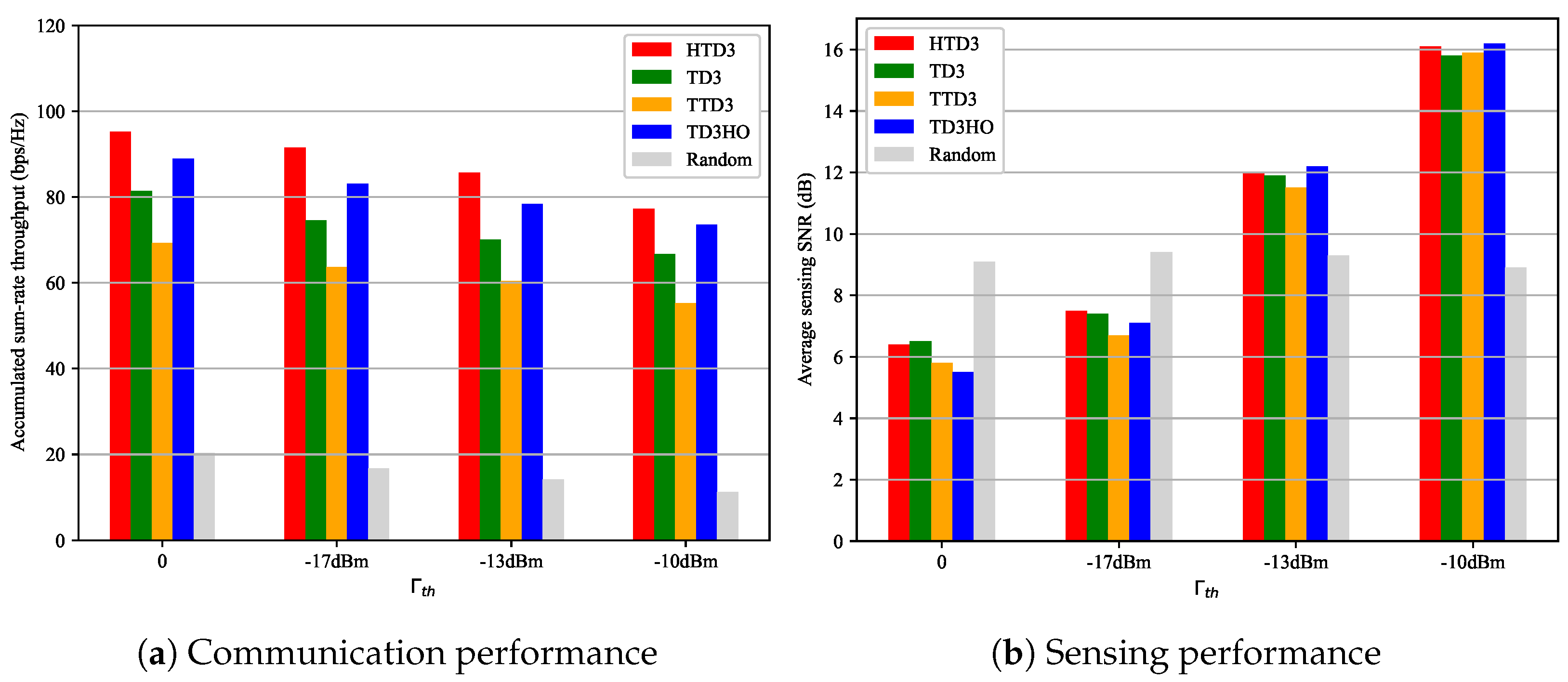
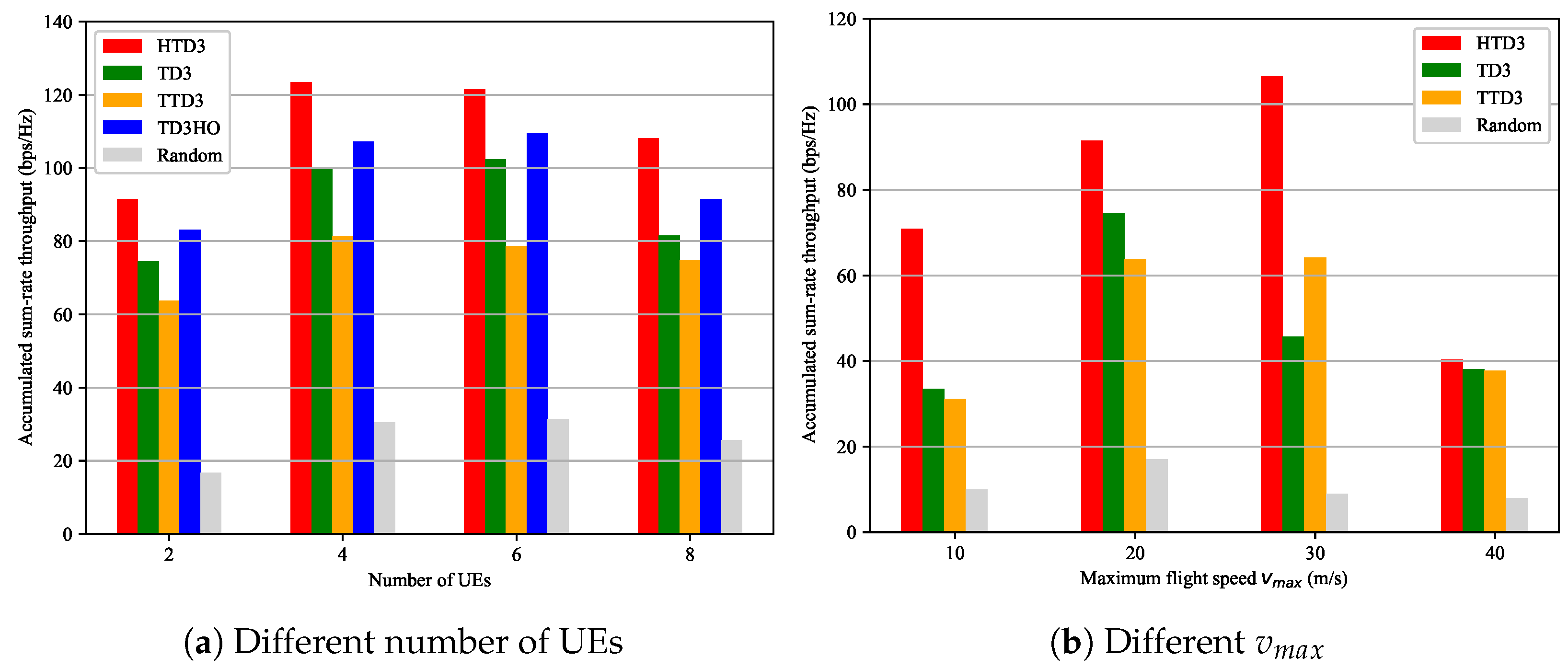
4.2. The Impact of Environmental Parameters on HTD3

Figure 4 presents the convergence performance of the proposed HTD3 via different environment parameters. For the environment with two UEs, we set the thresholds Γ t h to 0, −17 dBm, and −13 dBm, respectively. As shown in Figure 4a, it can be noticed that with a higher sensing performance threshold, the curves converge more slowly; this is because for a higher sensing performance threshold, the agents need more rounds to learn how to ensure successful sensing while maximizing communication performance. For Γ t h = 0 , the curve converges to the highest accumulated sum-rate throughput; the obvious reason is that the UAV does not need to allocate the power resources to sensing in this case. Correspondingly, for Γ t h = 13 dBm, the curve converges to the lowest value since the high demand for sensing performance leads to a decrease in communication performance, as more power resources are allocated to sensing to ensure the successful sensing of the targets. Then, we set different number of UEs with a sensing performance threshold Γ t h = 17 dBm. As shown in Figure 4b, at the beginning, all curves keep fluctuating, and then maintain convergence after a sharp rise in a certain round. It can be noticed that, as the number of UEs increases, the curve needs more rounds to converge; this is because the complexity of the environment increases. It can also be observed that the highest sum-rate throughput is achieved when the number of UEs is six, while the achieved sum-rate throughput decreases when the number of UEs is eight. This is because limited power resources are insufficient to support communication for more UEs; the system cannot improve communication performance with multiple UEs while ensuring successful sensing in this case.
As shown in Figure 5, we observe the accumulated sum-rate throughput via different maximum transmission power ( P m a x ) and transmission scenarios with or without RIS. First, as the maximum transmission power increases, the accumulated sum-rate throughput increases; this is because higher power leads to a higher transmission rate within the given power range. Next, the higher the sensing performance threshold Γ t h , the lower the accumulated sum-rate throughput; the reason is that a higher sensing demand results in more power resources being allocated to sensing, which leads to a reduction in resources used for communication. Finally, the achieved accumulated sum-rate throughput of scenarios with the RIS is significantly higher than the scenarios without the RIS, which indicates that the deployment of the RIS effectively enhances the communication performance of the system.

4.3. Benchmark Schemes

To verify the effectiveness and superiority of our proposed algorithm, we compare the following benchmark algorithms with the algorithm we proposed:
(1)
TD3: We use TD3 to jointly control the trajectory of the UAV, the beamforming matrix of the UAV, and the passive beamforming matrix of the RIS. Differently from HTD3, all actions are output by one actor network. We use this benchmark to verify the effectiveness of decomposing the original problems.
(2)
TTD3: TTD3 was proposed in [25] and uses two agents to output two different sets of actions. In this article, in the TTD3 case, two agents are adopted to adjust the location of the UAV and handle the sensing and communication tasks. Differently from HTD3, which is a hierarchical structure, although both TTD3 and HTD3 contain two agents, TTD3 adopts a parallel structure, which outputs all actions simultaneously. We use this benchmark to verify the effectiveness of our hierarchical structure design.
(3)
TD3 with Hovering Only (TD3-HO): We use TD3 to jointly control the beamforming matrix of the UAV and the passive beamforming matrix of the RIS, while the UAV hovers at a fixed position. We use this benchmark to verify the effectiveness of the optimization of the trajectory.
(4)
Random action: The UAV randomly executes actions. We use this benchmark to verify the effectiveness of DRL.
Figure 6 shows the accumulated sum-rate throughput of the different algorithms when there are two UEs in the scenario, Γ t h = 17 dBm and P m a x = 1 W. Since all these algorithms adopt the TD3 structure, all learning rates are set to 0.001. The solid lines in the figure represent the mean values obtained by each algorithm under multiple experiments, while the shaded areas represent the fluctuation range of the curve. It can be observed that our proposed HDRL with an HTD3 structure achieves the highest accumulated sum-rate throughput and the smallest fluctuation. The convergence values obtained by the proposed algorithm are 33%, 50%, and 10% higher than TD3, TTD3, and TD3HO, respectively. All DRL-based schemes achieve a significantly higher accumulated sum-rate throughput to random action schemes due to the learning of agents. All curves with DRL schemes converge between 200 and 250 episodes, and stabilize at the convergence value with some fluctuations. The performance of HTD3 is superior to that of TD3 and TD3HO; the apparent reason is that each layer of HTD3 has lower action space and state space, which significantly improves the performance of learning. Conversely, it can be noticed that the curve of TD3 fluctuates greatly, and TD3HO achieves smaller fluctuations and higher convergence values. Although the TD3 scheme considers trajectory optimization, the increase in the dimensions of action space and state space leads to a decrease in algorithm performance. Furthermore, through comparing HTD3 with TTD3, we conclude that a hierarchical structure is superior to a parallel structure since HTD3 uses an upper network agent to optimize the lower network agent whereas TTD3 uses two agents to simultaneously maximize rewards. Even though they both split the action space and state space and adopt multiple agents, the hierarchical structure takes into account the relevance between agents while the parallel structure ignores it. Above all, the proposed HDRL with an HTD3 stucture has the best learning performance in the RIS-aided UAV-ISAC network.
Figure 7 shows the obtained trajectory with different algorithms. For HTD3 with sensing only (i.e., the UAV only performs sensing tasks to maximize the sensing beampattern gain [2]), it can be noticed that, in this case, the UAV flies directly towards the sensing area when adopting HTD3. This is because the UAV does not have to focus on communication and it will maximize sensing beampattern gain by approaching the sensing targets. We can observe that TD3 adopts a significant range of movement, while the moving distance of HTD3 is obviously shorter than that of TD3; this is because with the decomposing of the problem, the UAV provides clearer control over movement distance due to the lower action space. However, TD3 optimizes the trajectory with other actions, which leads to a greater probability of falling into local optima. Moreover, since the UAV first chooses a location and then performs sensing and communication with a fixed location for Δ time slots in the HTD3 case, the agent tends to reduce the movement distance to promote network convergence. When adopting TTD3, the movement of the UAV is extremely limited; this is because in the parallel structure, agents in TTD3 cannot observe global information, and hence the agent is unable to optimize the trajectory.
Figure 8 represents the communication and sensing performance via different sensing thresholds Γ t h . As shown in Figure 8a, a higher sensing performance threshold Γ t h leads to a lower sum-rate throughput for all algorithms; the obvious reason is that more power resources will be used for sensing when the sensing performance threshold is high, and, correspondingly, the burden of communication will increase. It can be observed that our proposed HTD3 always achieves the best performance with different γ t h . The achieved accumulated sum-rate throughput of random action is significantly low; this is because random beamforming matrix and trajectory cannot guarantee effective sensing and communication. TD3HO always outperforms TD3 and TTD3; the reason is that TD3HO has smaller and more stable state spaces due to the lack of trajectory optimization, and, moreover, TD3 and TTD3 are unable to effectively integrate trajectory optimization with the optimization beamforming matrix of the UAV and the passive beamforming matrix of the RIS. As shown in Figure 8b, when using random action, the obtained average sensing SNR remains almost unchanged; this is because the untrained UAV cannot allocate resources reasonably. It can be seen that after the training of DRL, the higher the sensing threshold γ t h , the higher the achieved average sensing SNR; the apparent reason is that more power resources need to be allocated to sensing to ensure successful transmission. Notably, our proposed algorithm does not show significant improvement in sensing performance compared to other DRL approaches; this is because our goal is to optimize communication performance while meeting sensing requirements. In other words, all DRL approaches only learn how to allocate power resources to meet sensing requirements, and sensing performance itself is not an optimization goal.
Figure 9 illustrates the accumulated sum-rate throughput performance of various algorithms in scenarios with different parameters. As shown in Figure 9a, an increase in the number of UEs within a certain range (i.e., from two UEs to six UEs) leads to an increase in sum-rate throughput. When there are eight UEs in the scenario, the performance of all algorithms significantly decreases since a large number of UEs causes insufficient communication and sensing resources. The HTD3 we proposed still achieves the best performance under this trend. Figure 9b demonstrates the accumulated sum-rate throughput with different maximum flight speeds v m a x ; since TD3HO has no trajectory optimization, we do not consider TD3HO with different v m a x . When v m a x = 10 m/s, v m a x = 20 m/s, and v m a x = 30 m/s, the proposed HTD3 significantly outperforms other benchmarks, which illustrates that our proposed algorithm could better optimize the trajectory. In particular, it can be noticed that TD3 outperforms TTD3 when v m a x = 20 m/s and TTD3 outperforms TD3 when v m a x = 30 m/s. The performance of all algorithms is almost identical when v m a x = 40 m/s; this is because the excessive maneuverability of the UAV leads to the inability of intelligent agents to adapt to changes of state.

5. Conclusions

This paper considers a RIS-aided UAV-ISAC scenario, where the UAV communicates with multiple UEs and performs sensing towards targets simultaneously. Subject to the constraints on the maximum transmission power, maximum flight speed, and minimum sensing beampattern gain requirements, we jointly optimize the trajectory of the UAV, the beamforming matrix of the UAV, and the passive beamforming matrix of the RIS to maximize the sum-rate throughput of the system. We decompose the original problem into a trajectory optimization problem and a sum-rate throughput maximizing problem, and a novel HDRL framework is proposed to alternately solve them. Differently from the existing DRL approaches, our proposed method obtains higher performance by solving two MDPs with smaller state space and action space. The simulation results with different parameters show the effectiveness of the proposed scheme in maximizing the sum-rate throughput, which is significantly better than TD3, TTD3, and TD3HO. Future works will consider the multi-UAV scenario, and we will consider how to extend HDRL to multi-agent reinforcement learning or federated learning in multi-UAV scenarios. Moreover, more precise measurement standards will be adopted to measure the performance of the system.

Author Contributions

Conceptualization, H.C.; methodology, H.C.; software, H.C.; validation, H.C. and R.W.; formal analysis, H.C. and H.L.; investigation, H.C.; resources, H.C.; data curation, H.C.; writing—original draft preparation, H.C. and X.Z.; writing—review and editing, H.C. and J.M.; visualization, H.C.; supervision, J.M.; project administration, J.M.; funding acquisition, J.M. All authors have read and agreed to the published version of the manuscript.

Funding

This research received no external funding.

Data Availability Statement

The data presented in this study are available in Section 4.

Conflicts of Interest

The authors declare no conflicts of interest.

References

  1. Lu, S.; Liu, F.; Li, Y.; Zhang, K.; Huang, H.; Zou, J.; Li, X.; Dong, Y.; Dong, F.; Zhu, J.; et al. Integrated Sensing and Communications: Recent Advances and Ten Open Challenges. IEEE Internet Things J. 2024, 11, 19094–19120. [Google Scholar] [CrossRef]
  2. Lyu, Z.; Zhu, G.; Xu, J. Joint Maneuver and Beamforming Design for UAV-Enabled Integrated Sensing and Communication. IEEE Trans. Wirel. Commun. 2023, 22, 2424–2440. [Google Scholar] [CrossRef]
  3. Deng, C.; Fang, X.; Wang, X. Beamforming Design and Trajectory Optimization for UAV-Empowered Adaptable Integrated Sensing and Communication. IEEE Trans. Wirel. Commun. 2023, 22, 8512–8526. [Google Scholar] [CrossRef]
  4. Luo, H.; Liu, R.; Li, M.; Liu, Q. RIS-Aided Integrated Sensing and Communication: Joint Beamforming and Reflection Design. IEEE Trans. Veh. Technol. 2023, 72, 9626–9630. [Google Scholar] [CrossRef]
  5. Sankar, R.S.P.; Chepuri, S.P.; Eldar, Y.C. Beamforming in Integrated Sensing and Communication Systems with Reconfigurable Intelligent Surfaces. IEEE Trans. Wirel. Commun. 2024, 23, 4017–4031. [Google Scholar] [CrossRef]
  6. Long, X.; Zhao, Y.; Wu, H.; Xu, C.Z. Deep Reinforcement Learning for Integrated Sensing and Communication in RIS-assisted 6G V2X System. IEEE Internet Things J. 2024. early access. [Google Scholar] [CrossRef]
  7. Saikia, P.; Singh, K.; Huang, W.J.; Duong, T.Q. Hybrid Deep Reinforcement Learning for Enhancing Localization and Communication Efficiency in RIS-Aided Cooperative ISAC Systems. IEEE Internet Things J. 2024, 11, 29494–29510. [Google Scholar] [CrossRef]
  8. Meng, K.; Wu, Q.; Xu, J.; Chen, W.; Feng, Z.; Schober, R.; Swindlehurst, A.L. UAV-Enabled Integrated Sensing and Communication: Opportunities and Challenges. IEEE Wirel. Commun. 2024, 31, 97–104. [Google Scholar] [CrossRef]
  9. Liu, Z.; Liu, X.; Liu, Y.; Leung, V.C.M.; Durrani, T.S. UAV Assisted Integrated Sensing and Communications for Internet of Things: 3D Trajectory Optimization and Resource Allocation. IEEE Trans. Wirel. Commun. 2024, 23, 8654–8667. [Google Scholar] [CrossRef]
  10. Meng, K.; Wu, Q.; Ma, S.; Chen, W.; Wang, K.; Li, J. Throughput Maximization for UAV-Enabled Integrated Periodic Sensing and Communication. IEEE Trans. Wirel. Commun. 2023, 22, 671–687. [Google Scholar] [CrossRef]
  11. Zhang, R.; Zhang, Y.; Tang, R.; Zhao, H.; Xiao, Q.; Wang, C. A Joint UAV Trajectory, User Association, and Beamforming Design Strategy for Multi-UAV-Assisted ISAC Systems. IEEE Internet Things J. 2024, 11, 29360–29374. [Google Scholar] [CrossRef]
  12. Wu, J.; Yuan, W.; Hanzo, L. When UAVs Meet ISAC: Real-Time Trajectory Design for Secure Communications. IEEE Trans. Veh. Technol. 2023, 72, 16766–16771. [Google Scholar] [CrossRef]
  13. Liu, Y.; Liu, X.; Liu, Z.; Yu, Y.; Jia, M.; Na, Z.; Durrani, T.S. Secure Rate Maximization for ISAC-UAV Assisted Communication Amidst Multiple Eavesdroppers. IEEE Trans. Veh. Technol. 2024, 73, 15843–15847. [Google Scholar] [CrossRef]
  14. Yu, X.; Xu, J.; Zhao, N.; Wang, X.; Niyato, D. Security Enhancement of ISAC via IRS-UAV. IEEE Trans. Wirel. Commun. 2024, 23, 15601–15612. [Google Scholar] [CrossRef]
  15. Zhang, J.; Xu, J.; Lu, W.; Zhao, N.; Wang, X.; Niyato, D. Secure Transmission for IRS-Aided UAV-ISAC Networks. IEEE Trans. Wirel. Commun. 2024, 23, 12256–12269. [Google Scholar] [CrossRef]
  16. Wu, Z.; Li, X.; Cai, Y.; Yuan, W. Joint Trajectory and Resource Allocation Design for RIS-Assisted UAV-Enabled ISAC Systems. IEEE Wirel. Commun. Lett. 2024, 13, 1384–1388. [Google Scholar] [CrossRef]
  17. Zhang, Z.; Zhang, Q.; Miao, J.; Yu, F.R.; Fu, F.; Du, J.; Wu, T. Energy-Efficient Secure Video Streaming in UAV-Enabled Wireless Networks: A Safe-DQN Approach. IEEE Trans. Green Commun. Netw. 2021, 5, 1892–1905. [Google Scholar] [CrossRef]
  18. Miao, J.; Bai, S.; Mumtaz, S.; Zhang, Q.; Mu, J. Utility-Oriented Optimization for Video Streaming in UAV-Aided MEC Network: A DRL Approach. IEEE Trans. Green Commun. Netw. 2024, 8, 878–889. [Google Scholar] [CrossRef]
  19. Yan, M.; Xiong, R.; Wang, Y.; Li, C. Edge Computing Task Offloading Optimization for a UAV-Assisted Internet of Vehicles via Deep Reinforcement Learning. IEEE Trans. Veh. Technol. 2024, 73, 5647–5658. [Google Scholar] [CrossRef]
  20. Yao, Y.; Miao, J.; Zhang, T.; Tang, X.; Kang, J.; Niyato, D. Towards Secrecy Energy-Efficient RIS Aided UAV Network: A Lyapunov-Guided Reinforcement Learning Approach. In Proceedings of the 2024 IEEE Wireless Communications and Networking Conference (WCNC), Dubai, United Arab Emirates, 21–24 April 2024; pp. 1–6. [Google Scholar] [CrossRef]
  21. Wang, Y.; Gao, Z.; Zhang, J.; Cao, X.; Zheng, D.; Gao, Y.; Ng, D.W.K.; Renzo, M.D. Trajectory Design for UAV-Based Internet of Things Data Collection: A Deep Reinforcement Learning Approach. IEEE Internet Things J. 2022, 9, 3899–3912. [Google Scholar] [CrossRef]
  22. Liu, Q.; Zhu, Y.; Li, M.; Liu, R.; Liu, Y.; Lu, Z. DRL-Based Secrecy Rate Optimization for RIS-Assisted Secure ISAC Systems. IEEE Trans. Veh. Technol. 2023, 72, 16871–16875. [Google Scholar] [CrossRef]
  23. Qin, Y.; Zhang, Z.; Li, X.; Huangfu, W.; Zhang, H. Deep Reinforcement Learning Based Resource Allocation and Trajectory Planning in Integrated Sensing and Communications UAV Network. IEEE Trans. Wirel. Commun. 2023, 22, 8158–8169. [Google Scholar] [CrossRef]
  24. Lim, H.K.; Ullah, I.; Kim, J.B.; Han, Y.H. Virtual Network Embedding Based on Hierarchical Cooperative Multiagent Reinforcement Learning. IEEE Internet Things J. 2024, 11, 8552–8568. [Google Scholar] [CrossRef]
  25. Tham, M.L.; Wong, Y.J.; Iqbal, A.; Ramli, N.B.; Zhu, Y.; Dagiuklas, T. Deep Reinforcement Learning for Secrecy Energy- Efficient UAV Communication with Reconfigurable Intelligent Surface. In Proceedings of the 2023 IEEE Wireless Communications and Networking Conference (WCNC), Glasgow, UK, 26–29 March 2023; pp. 1–6. [Google Scholar] [CrossRef]
  26. Yang, Z.; Miao, J.; Zhang, T.; Tang, X.; Kang, J.; Niyato, D. QoE Maximization for Video Streaming in Cache-Enable Satellite-UAV-Terrestrial Network. In Proceedings of the ICC 2024—IEEE International Conference on Communications, Denver, CO, USA, 9–13 June 2024; pp. 1–6. [Google Scholar] [CrossRef]
  27. Ren, T.; Niu, J.; Dai, B.; Liu, X.; Hu, Z.; Xu, M.; Guizani, M. Enabling Efficient Scheduling in Large-Scale UAV-Assisted Mobile-Edge Computing via Hierarchical Reinforcement Learning. IEEE Internet Things J. 2022, 9, 7095–7109. [Google Scholar] [CrossRef]
  28. Susarla, P.; Deng, Y.; Juntti, M.; Sílven, O. Hierarchial-DQN Position-Aided Beamforming for Uplink mmWave Cellular-Connected UAVs. In Proceedings of the GLOBECOM 2022—2022 IEEE Global Communications Conference, Rio de Janeiro, Brazil, 4–8 December 2022; pp. 1308–1313. [Google Scholar] [CrossRef]
  29. Khuwaja, A.A.; Chen, Y.; Zhao, N.; Alouini, M.S.; Dobbins, P. A Survey of Channel Modeling for UAV Communications. IEEE Commun. Surv. Tutor. 2018, 20, 2804–2821. [Google Scholar] [CrossRef]
  30. Khalili, A.; Rezaei, A.; Xu, D.; Schober, R. Energy-Aware Resource Allocation and Trajectory Design for UAV-Enabled ISAC. In Proceedings of the GLOBECOM 2023—2023 IEEE Global Communications Conference, Kuala Lumpur, Malaysia, 4–8 December 2023; pp. 4193–4198. [Google Scholar] [CrossRef]
Figure 1. The structure of the UAV-enabled ISAC system.
Drones 08 00717 g001
Figure 2. The structure of SMDP.
Drones 08 00717 g002
Figure 3. The structure of the proposed HDRL.
Drones 08 00717 g003
Figure 4. The performance of the proposed scheme via different parameters. (a) The sum-rate throughput of different threshold Γ t h . (b) The sum-rate throughput of different numbers of UEs.
Drones 08 00717 g004
Figure 5. The performance of the proposed scheme of maximum transmission power ( P m a x ).
Drones 08 00717 g005
Figure 6. The performance of different benchmarks.
Drones 08 00717 g006
Figure 7. Trajectory of UAV with different algorithms.
Drones 08 00717 g007
Figure 8. The communication and sensing performance of the algorithms via different sensing thresholds Γ t h . (a) The sum-rate throughput of different thresholds Γ t h . (b) The average sensing SNR of different thresholds Γ t h .
Drones 08 00717 g008
Figure 9. The performance of the algorithms via different environment parameters. (a) The sum-rate throughput of different numbers of UEs. (b) The sum-rate throughput of different v m a x values.
Drones 08 00717 g009
Table 1. Parameter table.
NotationDefinitionValue
HThe fixed altitude of the UAV40 m
z R The fixed altitude of the RIS15 m
AThe number of antennas of the UAV4
MThe number of antennas of the RIS4
δ f l y The flight time in each time slot0.1 s
ρ 0 The channel power gain at reference distance d 0 = 1 m−30 dB
ϵ L o S , ϵ N L o S The NLOS coefficients[2.3, 34] [29]
a p l , b p l The NLOS coefficients[27.23, 0.097] [29]
f c The carrier frequency2 GHz
v c The speed of light 3 × 10 8 m/s
s e The radar cross-section of targets1 m2
σ k 2 The noise power−114 dBm
P m a x The maximum transmission power of the UAV1 W
v m a x The maximum speed of the UAV20 m/s
N e p The training rounds1000
NThe number of time slots of each round100
Δ The steps of the lower layer network10
Disclaimer/Publisher’s Note: The statements, opinions and data contained in all publications are solely those of the individual author(s) and contributor(s) and not of MDPI and/or the editor(s). MDPI and/or the editor(s) disclaim responsibility for any injury to people or property resulting from any ideas, methods, instructions or products referred to in the content.

