1. Introduction
Unmanned aerial vehicles (UAVs) play a role of the utmost importance in the inspection of man-made infrastructures, e.g., power lines, wind turbines, transport infrastructures, buildings, industrial sites, and mines [
1,
2,
3,
4,
5,
6]. The design of an inspection drone is a complex task that consists of various individual sub-problems to be solved. The focus of this project has been on the inspection of vessels by using stereo vision and active object tracking. More specifically, the design of an autonomous multi-camera UAV drone is proposed for visual inspection tasks.
Utilizing an autonomous drone in inspection tasks can improve efficiency and speed without compromising quality. This work contributes with the assessment of the viability and advantages of using active vision mechanisms for active object detection and tracking in dynamic environments. More specifically, this paper investigates the advantages of an active tracking approach using a three-degree-of-freedom (DoF) gimbal system mounted on UAVs, by proposing a method for actively tracking spherical and planar objects in real time, using visual information. We test and evaluate our tracking methodologies in two different tracking scenarios in a realistic Gazebo simulation environment, the first for sphere tracking and the second for tracking fiducial planar surfaces.
Object recognition, localization, and tracking play a role of primordial importance in computer vision applications. However, it is still an extremely difficult task, in particular in scenarios where objects are attended using fast-moving UAVs that need to robustly operate in real time. Typically the performance of these vision-based systems is affected by motion blur and geometric distortions, to name but two issues. Gimbal systems are thus primordial to compensate for motion blur and ensure vision streams are stable. Finally, from an energetic standpoint, it is more efficient to move a lightweight gimbal system than the whole drone body. However, moving the body of the UAV cannot be avoided when mapping the surrounding environment.
In particular, this work evaluates the importance of gimbals in active perception systems, which are primordial in multiple applications, namely, in inspection and surveillance tasks. Our systematic evaluation and results provide important insights for the implementation of active vision-based mechanisms in autonomous drone applications, e.g., vehicle tracking and building inspection.
The rest of the article is organized as follows.
Section 2 covers the literature survey focusing on different drone applications and their designs together with related work on active tracking and object detection.
Section 3 describes the chosen drone design, the active vision approaches developed for UAV-based object tracking.
Section 4 presents comparison results between our methods and passive approaches. Finally,
Section 5 concludes and discusses the work.
2. Background
Different applications for aerial drones exist in the robotics and computer vision literature. Among those are the inspection of industrial sites [
7], seeding and monitoring in agriculture contexts [
8], traffic surveillance [
9], and construction management [
5], to name a few. For successful execution of these tasks, UAVs must be endowed with different sensors [
8], including IMUs for measuring angular rates and forces, magnetometers to measure magnetic fields, GPS to provide geolocation, barometers to measure pressure, and cameras and lidars, to be able to perceive and interact with the surrounding environment, machine vision, and artificial intelligence algorithms.
In the remainder of this section we cover the related work on object detection and tracking.
2.1. Object Detection
The ability to actively track an object requires object detection in the image plane. Two simple object types will be considered when evaluating the active tracker; a colored sphere and a plane fiducial marker.
In this work, spherical detection in spatial coordinates is utilized in the assessment of the active tracking performance. In related work [
10] the authors propose a closed-form geometric solution of sphere location in 3D. The solution assumes a calibrated pin-hole camera model, which imposes a limitation resulting in poor performance when dealing with distorted images. Furthermore, they show that the projection of a sphere onto the image plane is an ellipse within the 5D parameter space (x-, y-center, major axis, minor axis, and orientation), while the circle fitting approach only requires 3D parameters (x-, y-center, and radius). Therefore, estimating an ellipse with a circle can significantly reduce the computational complexity.
In the work of [
11] the authors propose an automatic generation and detection method for square-based fiducial markers, namely ArUco library [
12]. The technique allows pose estimation of the ArUco marker and the camera pose. The detector heavily relies on vision-based perception which is highly affected by image gathering quality. Different sources of noise include image distortion, motion blur, and mechanical vibrations which result in different estimation errors. One way of compensating for visual distortion is by actively centering the target object in the center of the camera field of view.
2.2. Active Tracking by Viewpoint Control
Multiple strategies can be used in order to actively track an object target using a UAV. For instance, the position of the UAV can be changed, the orientation of the camera can be changed by the use of a pan and tilt system, or multiple cameras can be used.
In this work, the focus is on active object tracking using a gimbal system. By centering the object in the image where radial distortion is smaller and also by limiting the noise due to vibrations [
13], gimbals can be used successfully in active object tracking applications. Even though several high-performance visual tracking algorithms exist [
14,
15,
16], many are computationally demanding and rely on parallel processing units [
17,
18], thus being unsuited for the limited on-board computation capabilities of small UAVs [
19].
In an autonomous vision-based target tracking system by Cheng et al. [
20] they define an error in the distance and angle between the UAV and the tracked object. By controlling the velocity and the angular velocity of the UAV they ensure that the distance error and angular error converge to zero. In [
20] they propose a
following mode where they move the UAV while simultaneously controlling the yaw angle of the gimbal. They assume a constant height of the UAV to simplify the control problem to a planar control problem. In their approach, they use a Kernelized Correlation Filter (KCF) [
21] together with an Interacting Multi-Model Extended Kalman Filtering (IMM-EKF) [
22] based target state estimator.
In the work by [
23], the authors propose to use a three-DoF gimbal carrying a cinematography camera, to keep a moving target within the center of the image. The visual detection method is based on a CNN-based object tracker and the controller on an inner–outer loop structure. The inner loop has a higher bandwidth for tracking angular rates and the outer loop handles the tracking and pointing [
24]. In this work, an inner–outer loop structure is adopted, since the chosen three-DoF gimbal already implements an inner-loop controller.
3. Methodology
In the following section, the method used to create the inspection drone is explained. First, the proposed multi-camera drone system is described. Second, the overall navigation system is overviewed, and then we go deep into the details on the implemented active vision mechanism for object detection and tracking using gimbals.
3.1. System Overview
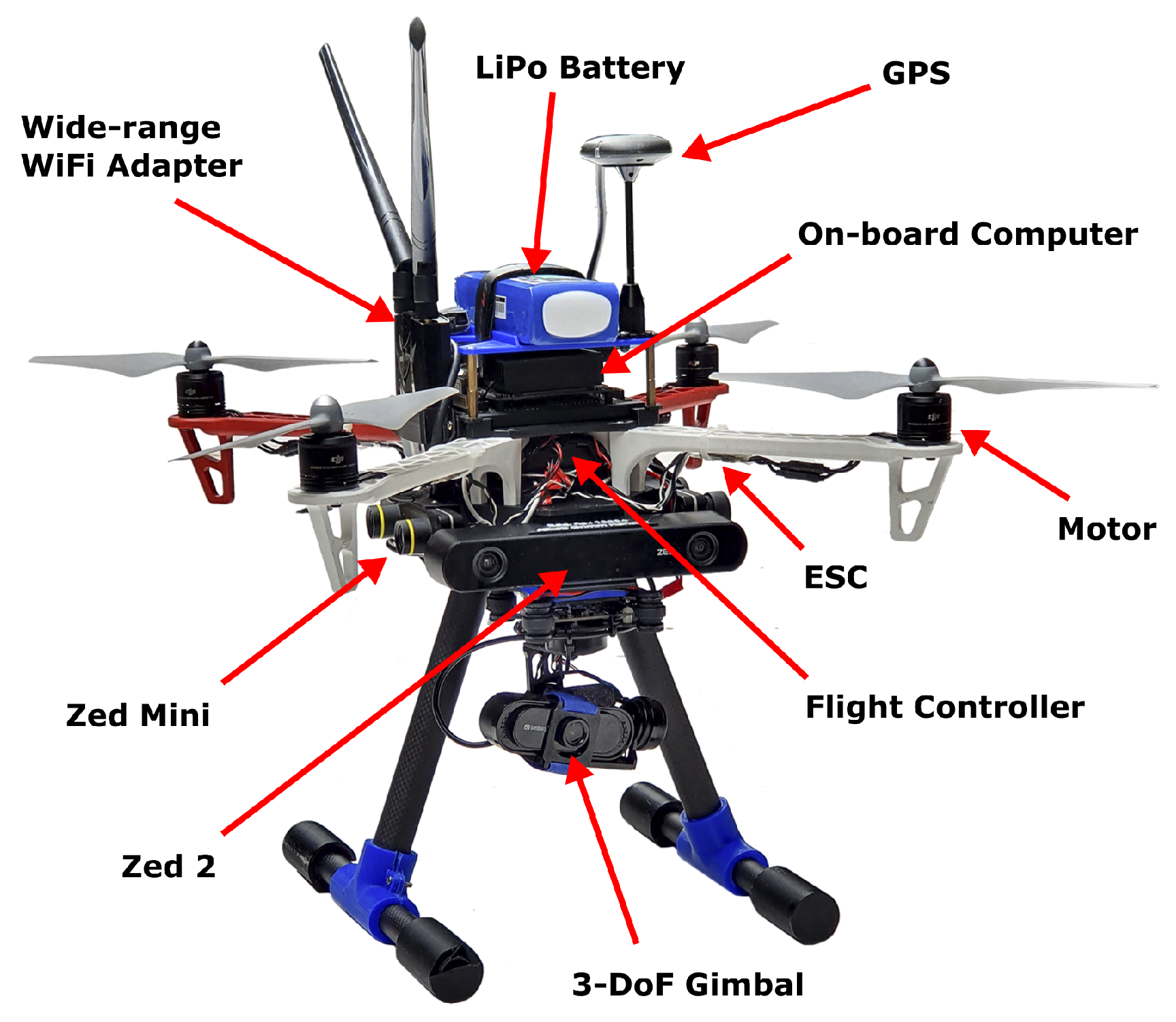
The proposed UAV design provides a system for autonomous navigation and mapping tasks. The system is embedded with multiple cameras and a flight controller that comprises IMU, altimeter, and low-level control. All the components, quantity, and weight are displayed in
Table 1.
The implemented hardware design focuses on minimizing weight to achieve better flight performance and a maximized flight duration until battery depletion. The UAV is a quadrotor base frame (DJI F450) that has been modified in order to mount the required sensors for inspection tasks. Sensors are placed where vibrations are avoided to achieve high-quality data sampling. Furthermore, stereo camera sensors are placed in orthogonal directions to maximize visual coverage.
Jetson Xavier NX is chosen as the on-board computer and a
Pixhawk 4 as the low-level flight controller. The chosen stereo camera sensors are
Zed 2 and
Zed Mini, since they are suitable for visuo-inertial navigation. The cameras are rigidly attached to the UAV base (see
Figure 1); consequently, their poses are assumed deterministic and known with respect to the base frame of the UAV body.
The navigation system exploits an off-the-shelf SLAM algorithm with loop closing and re-localization capabilities [
25]. The input fed into ORB-SLAM2 is an RGB-D point cloud that is provided by multiple stereo cameras. The VIO and IMU measurements are fused using an Extended Kalman Filter (EKF) for improved robustness on self-motion tracking performance.
Finally, a gimbal system has been added for tasks that require high-quality vision measurements, and the ability to actively and quickly fixate different locations within the environment, and smoothly track moving objects, without the need to move the drone base.
3.2. Active Tracking
The active tracking method is composed of object detection and gimbal control algorithm.
Two methods are considered for estimating the spatial coordinates of tracked objects, the first for colored spherical objects and the second for ArUco markers [
11]. Both methods use the pinhole camera model. Let
denote the intrinsic camera matrix,
where
,
together with the location
express the horizontal and vertical focal length and the principal point [
26]. Notice that the skew between the focal lengths is assumed to be zero. The intrinsic camera matrix can be utilized to calculate the corresponding 2D image points (
) from 3D object points (
),
3.2.1. Spherical Object Detection
When the center of a sphere is not located at the principal axis, the projection of the sphere in the image plane has an ellipsoid shape. This is shown in
Figure 2.
By assuming the spherical target is far away from the image plane, the ratio between the major and minor axis of the ellipse will be close to one [
10]. The assumption allows estimation of the 3D position mainly from the radius of the detected circle in the image plane. Estimating a circle is less computationally complex than estimating an ellipse. From the focal length (
f), the radius of the real sphere (
r), and the radius of the detected circle (
R) an estimate of the distance from the image plane to the sphere (
d) is estimated,
The back-projection of a pixel in the image corresponds to a ray in a spatial space. The 3D ray will travel from the principal point (C) to the detected center pixel in the image (X) and can be calculated from the normalized image coordinates. The normalized image coordinates are denoted by
and can be calculated from the inverse intrinsic camera matrix,
The normalized image coordinates are unit-less and have a unitary magnitude in the z-component. The final estimated spatial position of the sphere from the image can be computed by multiplying the estimated distance with the normalized coordinates. Let
denote the estimated center of the sphere,
The applied method is an estimate of the spatial sphere center from the image plane. A difference between the observed diameter and the actual diameter is seen in
Figure 3.
If the exact spatial position of a sphere is to be computed it can be carried out from a detected ellipse in the image plane. The equation of the cone that passes through the ellipse with the vertex at the center of projection is utilized to compute the 3D position of the sphere center [
27].
The circle detection in the image plane is implemented in a computationally simple manner. Simplicity is chosen in order to have a real-time active tracker (minimum 30 fps).
The steps in the circle detection process are the following:
The input image is converted from RGB to HSV, to facilitate color-based detection and tracking, since it separates the color information from the brightness information, being more robust to varying lighting conditions.
Thresholding is used to create a binary mask.
Contours are detected in the image.
The largest contour is used to compute a minimum enclosing circle.
The image contour is calculated from the binary image using the binary border following the fast and effective algorithm by Suzkui and Abe [
28].
The calculation of the circle center and radius in the image plane are performed by a minimum enclosing circle algorithm by Emo Welzl [
29], which is based on a Linear Programming algorithm. The found circle is the minimum circle that completely covers the object with a minimum area. This is shown in
Figure 4.
3.2.2. Plane Detection
The pose of a square-shaped planar surface can be detected in real time from point correspondences between known points. The open-source ArUco library enables pose detection of the ArUco markers. The outer rectangle is used for pose estimation, while the inner region is used for identification.
The approach for detecting the pose of an ArUco marker consists of
image segmentation with local adaptive thresholding. Then,
contour extraction is performed using the Suzuki and Abe algorithm similar to the sphere detector. Afterward, polygons are approximated using the Douglas–Peucker [
30] algorithm, where polygons not consisting of 4-vertex polygons are discarded. The last step is the
marker code extraction where the inner region is analyzed after protective projection has been removed with the use of a homography matrix.
3.2.3. Gimbal Control System
The active tracking is performed by changing the orientation of the gimbal. Three motors (yaw, pitch, roll) allow a 3-DoF change in orientation of the camera attached to the gimbal. The gimbal system utilizes an inner–outer loop structure. The inner loop is a PID controller that takes care of the angular rates and rejects disturbances based on gyro samples. The outer loop is responsible for pointing the camera towards the target object being tracked.
The control system is shown in
Figure 5. The block named
3-DoF Gimbal consists of three motors and an IMU for measuring the current angular velocity of the stabilized platform. The
monocular camera is mounted on the stabilized platform of the gimbal and outputs the tracked object in the image in pixel coordinates.
The low-level inner-loop controller is a closed-loop controller that calculates the error in velocity in yaw, pitch, and roll (
,
,
). The error is fed into a PID controller, which is utilized for control of the yaw, pitch, and roll angular rates, and which is tuned using the Ziegler–Nichols method [
31].
The error in the image plane is calculated as , where u is the detected center of the tracked object, is the center of the image, and is the error in the u-coordinate of the image plane.
3.2.4. Gimbal Kinematics Model
The main objective regarding the gimbal kinematics is to get the camera extrinsic transformation. The camera extrinsic is used to transform the detected object position in the camera frame to the world frame. The motivation for deriving the gimbal kinematics is that the known ground truth in the simulation of the tracked object is defined in the world frame and the estimated object position is in the camera frame.
The systematic procedure known as Denavit–Hartenberg (DH) convention [
32] is utilized to calculate the end effector of the gimbal [
33]. A Denavit–Hartenberg parameter table is the first step for calculating the kinematics of the gimbal. The forward kinematics is the cumulative effect of all the joint variables. A robot manipulator with
n joints has
links, where the first link is fixed; in the gimbal case, the fixation is to the rigid body of the UAV.
Four rules must be respected when drawing the Denavit–Hartenberg frames.
z-axis must be the axis of revolution or motion;
x-axis must be perpendicular to the z-axis of the frame before it;
x-axis must intersect the z-axis of the frame before it;
the y-axis follow the right hand rule.
The DH coordinate frame assignment for the 3-DoF gimbal is shown in
Figure 6. The fact that the rules must be respected when drawing the DH frames, consequently, makes it advantageous to set the joint states as in
Figure 7. This reduces the need for an extra frame, thus making the analysis easier.
After the DH coordinate frames have been assigned, the transformation for reference frame
can be calculated as
where the four parameters
,
,
, and
are associated with link
i and joint
i.
denotes rotation of frame
around
needed to align
and
(positive rotation following the right-hand-rule convention).
denotes rotation of frame around needed to align and .
denotes displacement from frame to frame i measured only in the direction.
denotes displacement from frame to frame n measured only in the direction.
The transformations for each link are multiplied in order to get the transformation between the base link and the end effector, according to,
4. Results
The result section presents both simulation and real-world results regarding the performance of active and passive object tracking using a gimbal system mounted on a UAV.
4.1. Active Tracking Using the Gimbal
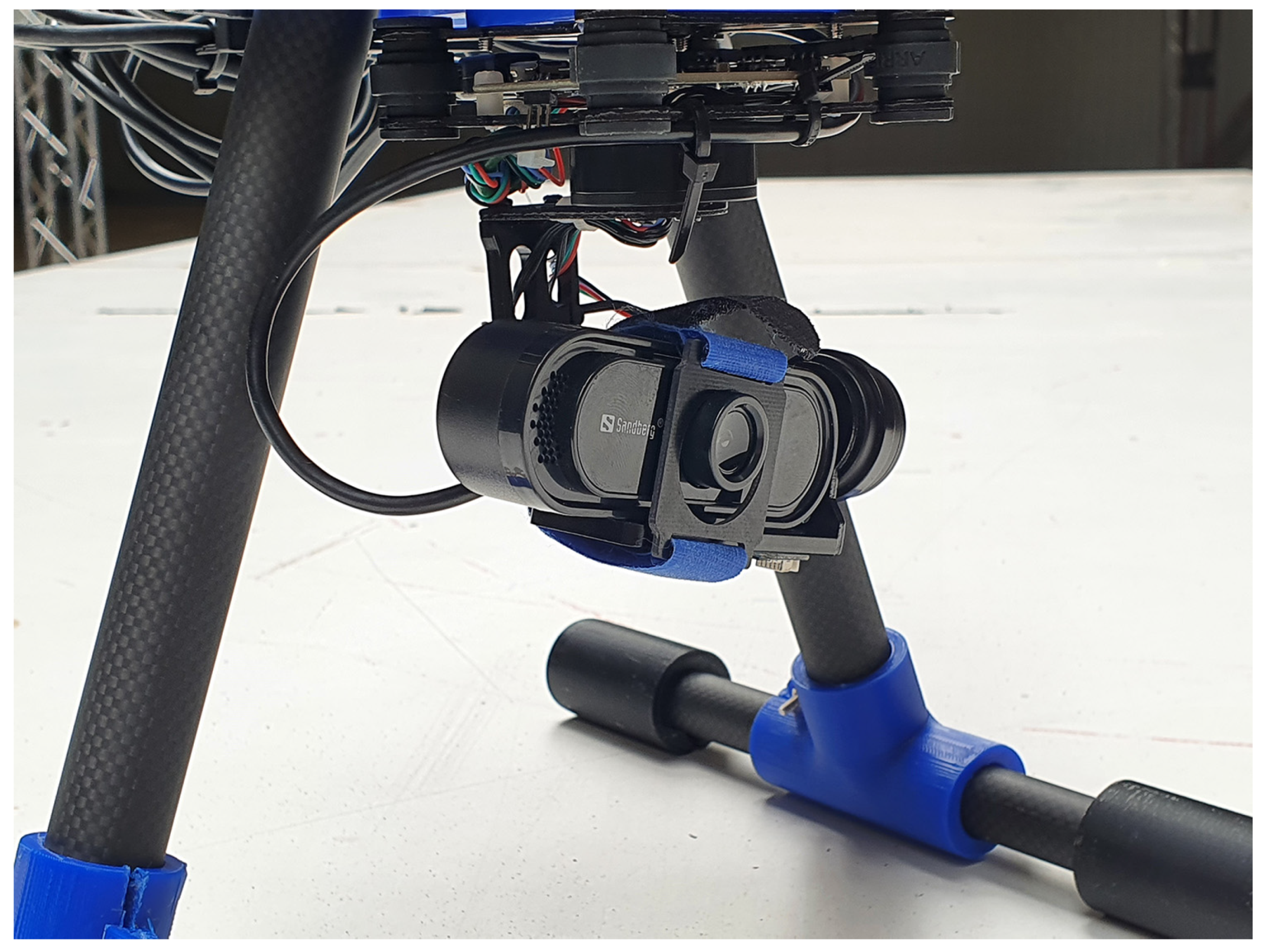
To evaluate the active object tracking method, the HawkRC Storm32 three-axis brushless gimbal system (please see
Figure 8) has been selected. The gimbal comprises three motors, two IMUs, and an open-source ROS-supported serial interface that allows for real-time position control. A simple CAD model has been created for simulation purposes, see
Figure 9.
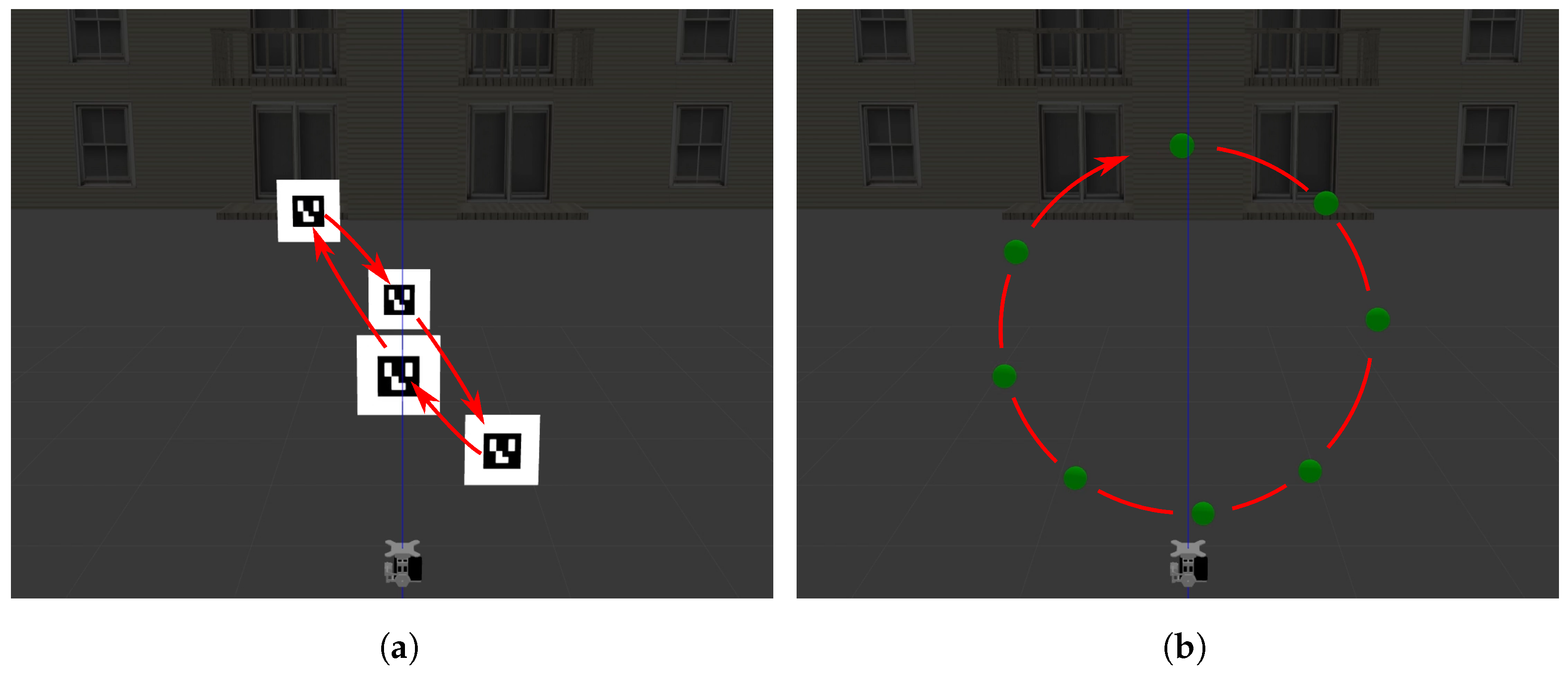
The gimbal experiments are conducted in a different simulation environment from the dry dock to evaluate the performance of the active tracking decoupled from the rest of the system. This allows for qualitatively measuring the performance of the proposed active tracking approach. The active tracking experimental setup is shown in
Figure 10.
The influence of active tracking has been compared with passive object tracking. Camera distortion, object type, and the moving trajectory of the object are the changed parameters for the experiments. To calculate the average error and the standard deviation, the object performs 10 revolutions with each parameter, where one revolution has a period of two seconds. In each experiment, the spatial coordinates of the object are estimated, and the Euclidean distance between the target object and the camera optical center is computed. The evaluation is based on the average error between the measured distance and the known ground truth distance.
The distorted camera is simulated in Gazebo [
34,
35] by applying the Brown–Conrady lens distortion model [
36], where
D represents the distortion radial factor coefficients,
Being radially symmetric, the distortion effect can be described using
, that represents the distance from the image center,
where the distortion is calculated by applying the distortion model,
4.1.1. Sphere Tracking Performance
The outcome of the performed experiments of the sphere object is shown in
Figure 11.
Non-distorted, circular: When considering the non-distorted camera type, the average distance error is less for active tracking compared with passive tracking. The explanation for the better performance by active tracking is that the method for estimating the spatial location of the sphere is assuming a projected circle in the image plane instead of an ellipse. This assumption is only valid in the center of the image.
Non-distorted, diagonal: The difference in the average error in the active and passive case is less. The reason for this is because the trajectory of the sphere is passing the principal point in the image plane. When the sphere is located at the principal point, the assumption about the circle being projected to the image plane becomes valid.
Distorted, circular: When a distorted camera type is applied, the distance error is higher compared to the non-distorted type. The distance estimate is based on the assumption about a calibrated camera image; consequently, the error in the distance is higher than the non-distorted case. Furthermore, one may note that the error becomes smaller when active tracking is applied. This is due to the fact that non-linear distortions (e.g., radial and tangential) are lower near the optical center and, thus, centering the object of interest in the camera center increases object detection accuracy.
Distorted, diagonal: Every time the sphere performs one round trip it passes the principal point twice, resulting in an average of less distortion. A less average distortion in the diagonal trajectory produces a smaller average error, compared to the circular trajectory where the sphere is at the peripheral of the image most of the experiment.
The estimate of the spherical center in x, y, z world coordinates for one revolution of the circular pattern is shown in
Figure 12. It turns out that the error mainly lies in the z-coordinate, but improvement is also seen in the x- and y-coordinates.
4.1.2. Fiducial Marker Tracking Performance
The outcome of the performed experiments with an ArUco marker object is shown in
Figure 13.
Non-distorted, circular: Having a non-distorted camera and utilizing the ArUco marker detection method shows the best performance across all experiments. There is not seen any difference between the active and passive tracking type, since the method is not assuming the target object being at the principal point.
Non-distorted, diagonal: The diagonal trajectory compared with the circular trajectory shows a slightly worse performance. One explanation could be the ArUco marker performing worse at a different maximal and minimal distance from the camera. The diagonal trajectory has a longer maximal distance and a shorter minimum distance compared with the circular trajectory.
Distorted, circular: The distorted case clearly has more distance error than the non-distorted case. This shows that the ArUco detector is sensitive to distortion. Active tracking results in a better distance estimate, which may be explained by having less optical distortion in the center of the image.
Distorted, diagonal: Similar to the sphere experiment it is seen that the diagonal trajectory results in a smaller distance error compared with the circular trajectory. Again, this is because of the target object passing the principal point in the image plane where distortion is lower.
A consequence of active tracking is that the image plane and the 2D surface of the ArUco marker are no longer parallel; this affects the spatial estimate in the distorted case. Even though the active tracking has a smaller error between the ground truth and the estimated distance, it introduces errors in the x- and y-coordinates, as shown in
Figure 14.
Although our set of experiments shows lower tracking errors on undistorted images, rectification introduces an extra computational time overhead. Image rectification is an extra step before pose estimation, that requires allocation of computational resources and, hence, introduces delays in the tracking control loop. Also, rectification of highly distorted images (e.g., fisheye), may create large rectification artifacts and jeopardize overall tracking performance,
Figure 14.
The computational complexity of calculating the distance to a spherical object can be reduced by assuming the object is at the principal point in the image and applying active tracking. This is advantageous in drone inspection applications, where computational power typically is limited. However, if high accuracy requirements are imposed on the estimate of the spatial coordinates of the sphere, then a computationally more complex method is needed.
4.1.3. Qualitative Assessment in the Real World
The simulation environment is not able to imitate camera motion blur; therefore, a bigger difference between the active vs passive tracking is expected when the gimbal is mounted to a real moving drone. Motion stabilization of the camera allows for higher quality images, which is necessary for spatial estimation from images. The qualitative assessment shows that our active tracking approach is able to track the target more robustly than the passive one.
Figure 15a,b show quantitative assessment of the active tracking performance.
Figure 15b shows a snapshot of a video sequence, in which the background is affected by motion blur but the moving sphere and hand are not. This is due to the angular movement of the gimbal trying to catch up with the sphere and centering it in the image plane.
5. Discussion and Conclusions
In this work, the main focus has been on the aerial robot design. Designing a complete autonomous UAV inspection system is a complex multi-disciplinary engineering task; thus, every design aspect cannot be covered. At the end of the project, a prototype including multiple stereo cameras was designed to perform the visual inspection tasks. Furthermore, a gimbal used for active tracking was evaluated in order to show the increased precision in visual object estimation and reduction in motion blur. Besides improving image quality by dampening vibrations, gimbals increase the field of view that possibly can be covered by the camera, since the orientation of the camera can be changed over time. An interesting task could be to combine a stereo camera and a gimbal solution to perform highly accurate mapping of the environment.
A simulation environment was developed in order to validate the optimal design for the UAV. A set of experiments suggests that active gimbal tracking can increase the spatial estimation accuracy of known-size objects in the case of a distorted image. This is due to a better visual performance in the center of a distorted image. Taking the spatial sphere detector and the fiducial ArUco marker detector into consideration, they are not useful in a vessel inspection task, since they are not present in the environment.
Although our simplistic experiments with a real camera and gimbal showed clear benefits, future work should be focused on quantitatively assessing the benefits of gimbal-based tracking approaches in real-world applications. A motion capture system must be utilized in order to evaluate the performance of active tracking in a real UAV system. The drone could be flying between two waypoints while tracking a target object. A motion tracking system should provide the ground truth position of the UAV and the tracked object. Also, a future promising research direction should be on evaluating how tracking performance is affected for different levels of lens distortion. We hypothesize that for high distortion cases (e.g., fisheye lenses) rectification might worsen detection and tracking performance, due to introduced rectification errors.
Finally, occlusion of tracked objects can happen while they are moving. If the tracked object is occluded while in motion, the proposed method will fail, since the tracked object is assumed to always be in line of sight. A visual tracking approach (e.g., a Bayesian filtering one), such as the IMM-EKF one of [
21], would improve the robustness of the employed detection methodologies, by filtering and associating noisy object detections across time, using a dynamic motion model.
Author Contributions
Conceptualization, J.G.H. and R.P.d.F.; methodology, J.G.H. and R.P.d.F.; software, J.G.H.; validation, J.G.H. and R.P.d.F.; formal analysis, J.G.H. and R.P.d.F.; investigation, J.G.H. and R.P.d.F.; data curation, J.G.H.; writing—original draft preparation, J.G.H. and R.P.d.F.; writing—review and editing, R.P.d.F.; supervision, R.P.d.F. All authors have read and agreed to the published version of the manuscript.
Funding
This research was partially funded by the Smart Industry Program (European Regional Development Fund and Region Midtjylland, grant no.: RFM-17-0020).
Data Availability Statement
The original contributions presented in the study are included in the article, further inquiries can be directed to the corresponding author.
Acknowledgments
The authors would like to acknowledge the financial contribution from the Smart Industry Program (European Regional Development Fund and Region Midtjylland, grant no.: RFM-17-0020). The authors would further like to thank Upteko Aps for bringing use-case challenges.
Conflicts of Interest
The authors declare no conflicts of interest.
References
- European Commission. Risk-Aware Automated Port Inspection Drone(s). Available online: https://cordis.europa.eu/project/id/861211 (accessed on 5 June 2021).
- European Commission. An Intelligent Inspection System for Improved and Efficient Power Line Cable Maintenance. Available online: https://cordis.europa.eu/project/id/720402 (accessed on 5 June 2021).
- European Commission. Autonomous & Intelligent UAV-Based Wind Turbine Inspection System for Cost-Effective, Reliable, Safe and Actionable Blade Fault Detection and Prediction. Available online: https://cordis.europa.eu/project/id/873395 (accessed on 5 June 2021).
- European Commission. Inspection Drones for Ensuring Safety in Transport Infrastructures. Available online: https://cordis.europa.eu/project/id/861111 (accessed on 5 June 2021).
- Li, Y.; Liu, C. Applications of multirotor drone technologies in construction management. Int. J. Constr. Manag. 2019, 19, 401–412. [Google Scholar] [CrossRef]
- Flyability. Indoor Drones in Mining. Available online: https://www.flyability.com/casestudies/indoor-drone-in-underground-mining-accessing-the-inaccessible (accessed on 5 June 2021).
- Chamoso, P.; Pérez, A.; Rodríguez, S.; Corchado, J.M.; Sempere, M.; Rizo, R.; Aznar, F.; Pujol, M. Modeling oil-spill detection with multirotor systems based on multi-agent systems. In Proceedings of the 17th International Conference on Information Fusion (FUSION), Salamanca, Spain, 7–10 July 2014; IEEE: Piscataway, NJ, USA, 2014; pp. 1–8. [Google Scholar]
- Mogili, U.R.; Deepak, B. Review on application of drone systems in precision agriculture. Procedia Comput. Sci. 2018, 133, 502–509. [Google Scholar] [CrossRef]
- Bozcan, I.; Kayacan, E. Au-air: A multi-modal unmanned aerial vehicle dataset for low altitude traffic surveillance. In Proceedings of the 2020 IEEE International Conference on Robotics and Automation (ICRA), Paris, France, 31 May–31 August 2020; IEEE: Piscataway, NJ, USA, 2020; pp. 8504–8510. [Google Scholar]
- Hajder, L.; Toth, T.; Pusztai, Z. Automatic estimation of sphere centers from images of calibrated cameras. arXiv 2020, arXiv:2002.10217. [Google Scholar]
- Garrido-Jurado, S.; Muñoz-Salinas, R.; Madrid-Cuevas, F.; Marín-Jiménez, M. Automatic generation and detection of highly reliable fiducial markers under occlusion. Pattern Recognit. 2014, 47, 2280–2292. [Google Scholar] [CrossRef]
- Muñoz Salinas, R.; Garrido-Jurado, S. ArUco Library. Available online: https://sourceforge.net/projects/aruco/files/ (accessed on 3 June 2021).
- Verma, M.; Collette, C. Active vibration isolation system for drone cameras. In Proceedings of the 14th International Conference on Vibration Problems, Crete, Greece, 1–4 September 2019; Springer: Cham, Switzerland, 2021; pp. 1067–1084. [Google Scholar]
- Smeulders, A.W.; Chu, D.M.; Cucchiara, R.; Calderara, S.; Dehghan, A.; Shah, M. Visual tracking: An experimental survey. IEEE Trans. Pattern Anal. Mach. Intell. 2013, 36, 1442–1468. [Google Scholar]
- Chen, P.; Dang, Y.; Liang, R.; Zhu, W.; He, X. Real-time object tracking on a drone with multi-inertial sensing data. IEEE Trans. Intell. Transp. Syst. 2017, 19, 131–139. [Google Scholar] [CrossRef]
- Qingqing, L.; Taipalmaa, J.; Queralta, J.P.; Gia, T.N.; Gabbouj, M.; Tenhunen, H.; Raitoharju, J.; Westerlund, T. Towards active vision with UAVs in marine search and rescue: Analyzing human detection at variable altitudes. In Proceedings of the 2020 IEEE International Symposium on Safety, Security, and Rescue Robotics (SSRR), Abu Dhabi, United Arab Emirates, 4–6 November 2020; IEEE: Piscataway, NJ, USA, 2020; pp. 65–70. [Google Scholar]
- Pan, N.; Zhang, R.; Yang, T.; Cui, C.; Xu, C.; Gao, F. Fast-Tracker 2.0: Improving autonomy of aerial tracking with active vision and human location regression. IET Cyber-Syst. Robot. 2021, 3, 292–301. [Google Scholar] [CrossRef]
- Kiyak, E.; Unal, G. Small aircraft detection using deep learning. Aircr. Eng. Aerosp. Technol. 2021, 93, 671–681. [Google Scholar] [CrossRef]
- Unal, G. Visual target detection and tracking based on Kalman filter. J. Aeronaut. Space Technol. 2021, 14, 251–259. [Google Scholar]
- Cheng, H.; Lin, L.; Zheng, Z.; Guan, Y.; Liu, Z. An autonomous vision-based target tracking system for rotorcraft unmanned aerial vehicles. In Proceedings of the 2017 IEEE/RSJ International Conference on Intelligent Robots and Systems (IROS), Vancouver, BC, Canada, 24–28 September 2017; IEEE: Piscataway, NJ, USA, 2017; pp. 1732–1738. [Google Scholar]
- Henriques, J.F.; Caseiro, R.; Martins, P.; Batista, J. High-Speed Tracking with Kernelized Correlation Filters. IEEE Trans. Pattern Anal. Mach. Intell. 2015, 37, 583–596. [Google Scholar] [CrossRef] [PubMed]
- Johnston, L.A.; Krishnamurthy, V. An improvement to the interacting multiple model (IMM) algorithm. IEEE Trans. Signal Process. 2001, 49, 2909–2923. [Google Scholar] [CrossRef] [PubMed]
- Cunha, R.; Malaca, M.; Sampaio, V.; Guerreiro, B.; Nousi, P.; Mademlis, I.; Tefas, A.; Pitas, I. Gimbal control for vision-based target tracking. In Proceedings of the European Conference on Signal Processing, A Coruña, Spain, 2–6 September 2019. [Google Scholar]
- Hurák, Z.; Rezac, M. Image-based pointing and tracking for inertially stabilized airborne camera platform. IEEE Trans. Control Syst. Technol. 2011, 20, 1146–1159. [Google Scholar] [CrossRef]
- Mur-Artal, R.; Tardós, J.D. ORB-SLAM2: An Open-Source SLAM System for Monocular, Stereo and RGB-D Cameras. IEEE Trans. Robot. 2017, 33, 1255–1262. [Google Scholar] [CrossRef]
- Andrew, A.M. Multiple view geometry in computer vision. Kybernetes 2001, 30, 1333–1341. [Google Scholar] [CrossRef]
- Shiu, Y.C.; Ahmad, S. 3D location of circular and spherical features by monocular model-based vision. In Proceedings of the Conference Proceedings, IEEE International Conference on Systems, Man and Cybernetics, Cambridge, MA, USA, 14–17 November 1989; IEEE: Piscataway, NJ, USA, 1989; pp. 576–581. [Google Scholar]
- Suzuki, S. Topological structural analysis of digitized binary images by border following. Comput. Vision Graph. Image Process. 1985, 30, 32–46. [Google Scholar] [CrossRef]
- Welzl, E. Smallest enclosing disks (balls and ellipsoids). In New Results and New Trends in Computer Science; Springer: Cham, Switzerland, 1991; pp. 359–370. [Google Scholar]
- Douglas, D.H.; Peucker, T.K. Algorithms for the reduction of the number of points required to represent a digitized line or its caricature. Cartogr. Int. J. Geogr. Inf. Geovis. 1973, 10, 112–122. [Google Scholar] [CrossRef]
- Ziegler, J.G.; Nichols, N.B. Optimum settings for automatic controllers. Trans. Am. Soc. Mech. Eng. 1942, 64, 759–765. [Google Scholar] [CrossRef]
- Denavit, J.; Hartenberg, R.; Mooring, B.; Tang, G.; Whitney, D.; Lozinski, C. 54 Kinematic Parameter. J. Appl. Mech. 1955, 77, 215–221. [Google Scholar] [CrossRef]
- Spong, M.W.; Hutchinson, S.; Vidyasagar, M. Robot Modeling and Control; John Wiley & Sons: Hoboken, NJ, USA, 2020. [Google Scholar]
- Gazebo. Camera Distortion. Available online: http://classic.gazebosim.org/tutorials?tut=camera_distortion&cat=sensors (accessed on 3 June 2021).
- OpenCV. Camera Calibration with OpenCV. Available online: https://docs.opencv.org/3.4/d4/d94/tutorial_camera_calibration.html (accessed on 6 June 2021).
- Conrady, A.E. Decentred Lens-Systems. Mon. Not. R. Astron. Soc. 1919, 79, 384–390. Available online: https://academic.oup.com/mnras/article-pdf/79/5/384/18250798/mnras79-0384.pdf (accessed on 20 March 2021). [CrossRef]
Figure 1.
Proposed UAV design for active inspection tasks.
Figure 1.
Proposed UAV design for active inspection tasks.
Figure 2.
Sphere projected down to the image plane resulting in a ellipsoid shape.
Figure 2.
Sphere projected down to the image plane resulting in a ellipsoid shape.
Figure 3.
Sphere model.(a) Sphere not aligned with the principal axis. (b) Sphere center in principal point.
Figure 3.
Sphere model.(a) Sphere not aligned with the principal axis. (b) Sphere center in principal point.
Figure 4.
Minimum enclosing circle for (a) an ellipse; (b) an irregular shape.
Figure 4.
Minimum enclosing circle for (a) an ellipse; (b) an irregular shape.
Figure 5.
Block diagram showing the gimbal control system. The inner loop handles velocities of the gimbal revolute joints. The outer loop is the tracked object in u, v coordinates. The reference u, v coordinates are the center of the image from the monocular camera.
Figure 5.
Block diagram showing the gimbal control system. The inner loop handles velocities of the gimbal revolute joints. The outer loop is the tracked object in u, v coordinates. The reference u, v coordinates are the center of the image from the monocular camera.
Figure 6.
Denavit–Hartenberg coordinate frames for a 3-DoF gimbal.
Figure 6.
Denavit–Hartenberg coordinate frames for a 3-DoF gimbal.
Figure 7.
Position of the joints when assigning the DH coordinate frames.
Figure 7.
Position of the joints when assigning the DH coordinate frames.
Figure 8.
HakRC Storm32 v1.3 mounted on the inspection UAV.
Figure 8.
HakRC Storm32 v1.3 mounted on the inspection UAV.
Figure 9.
Gimbal CAD model with individual part frames.
Figure 9.
Gimbal CAD model with individual part frames.
Figure 10.
Moving trajectory of the objects when executing the active tracking experiment. (a) Aruco moving in a diagonal circle trajectory. (b) Sphere performing a standing circle trajectory.
Figure 10.
Moving trajectory of the objects when executing the active tracking experiment. (a) Aruco moving in a diagonal circle trajectory. (b) Sphere performing a standing circle trajectory.
Figure 11.
Average distance error (±std) in the sphere scenario.
Figure 11.
Average distance error (±std) in the sphere scenario.
Figure 12.
Estimated x, y, z coordinates of the sphere object in world coordinates compared with ground truth (experiment parameters: sphere, non-distorted, circular trajectory).
Figure 12.
Estimated x, y, z coordinates of the sphere object in world coordinates compared with ground truth (experiment parameters: sphere, non-distorted, circular trajectory).
Figure 13.
Average distance error (± std) in the ArUco marker scenario.
Figure 13.
Average distance error (± std) in the ArUco marker scenario.
Figure 14.
Estimated x, y, z coordinates of the ArUco marker in world coordinates compared with ground truth (experiment parameters: ArUco, distorted, diagonal trajectory).
Figure 14.
Estimated x, y, z coordinates of the ArUco marker in world coordinates compared with ground truth (experiment parameters: ArUco, distorted, diagonal trajectory).
Figure 15.
(a) The detected ArUco marker. (b) The proposed active tracking performed on a real spherical object.
Figure 15.
(a) The detected ArUco marker. (b) The proposed active tracking performed on a real spherical object.
Table 1.
Drone hardware components.
Table 1.
Drone hardware components.
| Components | Quantity | Weight (g/pcs) |
|---|
| Holybro Pixhawk 4 (Pix4+PM07) | 1 | 15.8 + 36 |
| STorM32 V1.3 | 1 | 308 |
| sandberg usb webcam 1080p saver | 1 | 38 |
| DJI Framewheel 450 | 1 | 282 |
| DJI propeller (24 × 12.7 cm) | 4 | 13 |
| DJI 2312E 800KV Motor | 4 | 56 |
| DJI 430 Lite ESC | 4 | 11.6 |
| Jetson Xavier (NX+NGX004) | 1 | 85 + 33 |
| Alfa AWUS036ACH Long-range WiFi | 1 | 31 |
| ZED2 | 1 | 166 |
| ZED mini | 1 to 4 | 62.9 |
| LiPo Battery (4 s 5000 mAh) | 1 | 450 |
| 3D Printed Parts | 1 | 210 |
| UAV Total Weight | | 2062.1 |
| Disclaimer/Publisher’s Note: The statements, opinions and data contained in all publications are solely those of the individual author(s) and contributor(s) and not of MDPI and/or the editor(s). MDPI and/or the editor(s) disclaim responsibility for any injury to people or property resulting from any ideas, methods, instructions or products referred to in the content. |
© 2024 by the authors. Licensee MDPI, Basel, Switzerland. This article is an open access article distributed under the terms and conditions of the Creative Commons Attribution (CC BY) license (https://creativecommons.org/licenses/by/4.0/).


