Article

Design and Characterization of an Active Cooling System for Temperature-Sensitive Sample Delivery Applications Using Unmanned Aerial Vehicles

by
Ganapathi Pamula
1,
Lakshmi Pamula
1 and
Ashwin Ramachandran
2,*
1
Durham Academy, Durham, NC 27705, USA
2
Mechanical and Aerospace Engineering, Princeton University, Princeton, NJ 08544, USA
*
Author to whom correspondence should be addressed.
Drones 2024, 8(6), 270; https://doi.org/10.3390/drones8060270
Submission received: 30 April 2024 / Revised: 8 June 2024 / Accepted: 16 June 2024 / Published: 18 June 2024
(This article belongs to the Special Issue Evidence-Based Drone Innovation & Research for Healthcare)

Abstract

:
The transport of temperature-sensitive biological samples (blood, medicines, patient samples, vaccines, organs, etc.) to hard-to-reach places remains a challenge. This is especially true in places where infrastructure is limited, for which the use of unmanned aerial vehicles (UAVs) is an attractive solution. In this project, a cooling system compatible with on-board drone applications for the delivery of samples that require cold temperature storage and transportation was built, tested, and characterized. Specifically, a miniature polystyrene cooling unit with Peltier coolers was designed and built, enabling temperatures as low as −10 °C within the unit to be achieved. Further, passive and active cooling control strategies including the use of active feedback-control were explored to achieve a consistent temperature range between 2 °C and 8 °C. Finally, calculations of on-board power and battery weight required to achieve target cooling performance as a function of ambient environmental conditions are presented. Overall, this study presents an important step towards the design and development of drone-based technologies for temperature-sensitive sample delivery.

1. Introduction

Transporting small quantities of frozen goods, such as vaccines, to remote locations without adequate infrastructure is challenging and a problem that has been exacerbated by the recent COVID pandemic [1]. Unmanned aerial vehicle (UAV) technology has matured and is being used in search and rescue operations, transportation of goods, military operations, traffic monitoring, agriculture, and aerial photography [2,3,4,5]. Recent work has described UAV networks for the transport and processing of biological samples in urban areas, where UAVs leave from a central place within a city and return after delivering the samples [6,7]. UAVs are an ideal transportation solution to circumvent any terrain and infrastructure-related impediments for rapid transport. Further, research suggests that the use of drones for biological sample transportation does not adversely affect the integrity of the sample [8,9,10]. Therefore, drone-based solutions are likely to be very useful for a broad range of biological sample delivery applications to both hard-to-reach places and for nearby rapid transport [11,12,13,14].
In most existing studies involving drones for biological sample delivery, samples are typically kept frozen/cold on a UAV using passive methods such as dry ice, conditioned ice packs, and thermally sealed containers [15,16,17,18,19,20,21,22]. Both fixed wing [23] and multicopter [24] vehicles have been used to deliver vaccines and other medical products, however active cooling has not been demonstrated on either of these vehicles. While dry ice is an inexpensive method, it is not usable in the off-grid locations of resource-limited settings, where these solutions are typically needed.
The current method of using conditioned ice packs to cool vaccines is inefficient due to their weight. Studies have shown that ice packs, which typically weigh between 500 g to 1 kg, can occupy more than one-third of the UAV’s payload capacity, thereby reducing its range by up to 30% due to increased energy consumption and reduced flight stability [25,26] (see Table A1). Additionally, dry ice or ice packs do not allow closed-loop control of temperature, which may be required for certain payloads such as medicines that have to be maintained in a certain temperature range or samples that cannot be frozen [11,12]. For example, freezing liquid drugs such as insulin, can compromise their integrity if thawed quickly [27]. Therefore, active control of temperature on a UAV is essential.
A major alternative to passive cooling strategies is refrigeration. Though a refrigerator can be put on a UAV, the weight and power requirements that significantly cut down the range do not make this an attractive solution [15]. While there are multiple cooling methods [28] (see Table A1), thermoelectric modules using the Peltier effect are ideally suited because they are solid-state and light weight [29,30,31,32]. Furthermore, since a heavier battery would be required to drive the Peltier over longer flying distances, cooling requirements can often result in a tradeoff with the achievable flying time. For instance, a prior study [33] that used a thermoelectric cooler for drone-based delivery of samples was able to demonstrate the lowest stably maintained temperature of 12 °C for ~15 min flight time. This temperature range is well outside the range of maximum allowable temperatures for the refrigeration conditions as per the ICH guidelines [34], likely requiring a tradeoff with flight time to reach lower temperatures. Since thermoelectric coolers typically suffer from low energy efficiencies, there is also a need to increase the thermoelectric efficiency and minimize heat transfer losses of the cooler to both preserve cold temperatures so the batteries can be efficiently used and to increase flying time to reach more remote locations.
In addition, it is to be noted that different biologicals require storage and transportation at different temperatures [11,12]. Therefore, cooling systems for drones that are amenable to operating at different cooling temperatures are desirable. An example study [35] developed a cooler that operated at three distinct cooling temperatures. While the study represents a first step toward such variable temperature cooling operations and strategy, the lack of flexibility in operating a dynamically tunable range of operating temperatures limits the scope of the presented approach. One approach to address this challenge is to be able to dynamically use real-time schemes to monitor and control temperature within the cooler, as shown in a previous study [36]. However, the aforementioned study was able to demonstrate cooling only to as low as 24 °C for a 15 min flight time, thereby restricted in real-world applications that require refrigeration and below-freezing temperatures for biological samples.
The aforementioned background presents a pertinent and urgent challenge: How can vaccines and other frozen goods be safely transported via UAVs to remote locations and off-grid locations, while ensuring their viability upon arrival? According to UAV for Payload Delivery Working Group [37], since 2015, over half a million medical deliveries (e.g., blood, diagnostics specimens, vaccines, syringes, viral load samples, emergency medications, tuberculosis samples, sputum samples, etc.) have been made by UAVs in 39 countries across all continents (except Antarctica) with drones made by over a dozen companies. Interestingly, several state-of-the-art commercial drone solutions currently utilize passive cooling methods, again highlighting the limitations and challenges faced in UAV-based medical supply delivery. Moreover, incorporating conditioned ice packs for passive cooling in commercial drones, such as those from Swoop Aero [38] and Zipline [39], significantly impacts payload capacity and operational efficiency. Swoop Aero’s drones, designed for delivering medical supplies in remote areas, face limitations due to the weight and lack of precise temperature control associated with passive cooling methods. Zipline, known for its extensive network of medical supply deliveries, also relies on passive cooling, which can lead to temperature fluctuations and reduced flight range, especially in varied ambient conditions. Limitations of these commercial solutions highlight the need for advanced cooling systems that offer lightweight design and precise temperature management to enhance the reliability and range of UAV operations.
While several of the existing cooling solutions for drones have passive cooling mechanisms, to the best of our knowledge, none of these drones have demonstrated stable, tunable, and active cooling mechanisms that achieve temperatures spanning a range of both refrigeration and below-freezing conditions across a range of ambient to warm conditions. Our research introduces a novel approach to active cooling for UAVs by integrating a lightweight thermoelectric cooling unit with active feedback control mechanisms. Unlike previous studies that primarily focused on passive cooling methods, our system achieves and maintains temperatures as low as −10 °C, providing a broader operational range suitable for various biological samples. A significant innovation in our study is the implementation of an active feedback-control scheme that not only maintains precise temperature ranges (2 °C to 8 °C) but also improves energy efficiency. This is achieved by dynamically adjusting the cooling duty cycle based on real-time temperature readings, thereby reducing power consumption and extending the operational range of UAVs. Furthermore, our study presents a comprehensive analysis of the tradeoffs between battery capacity, payload weight, and cooling performance. This includes developing performance curves that guide the design and selection of battery and cooling components based on specific mission requirements and ambient conditions. Such detailed design strategies have not been quantified and addressed in existing literature.
Specifically, in this study, an experimental study and demonstration of an active cooling system designed for UAV applications that involve the delivery of temperature-sensitive samples is presented. For this, a thermoelectric cooling unit was custom-built and used to perform several ground-based tests to characterize the cooling performance. Specifically, the performance of the cooling unit with and without active cooling was compared as a function of the ambient temperatures. Further, a feedback-controlled scheme was implemented to achieve precise temperature control and energy-efficient cooling via reduced duty cycles. Thereafter, simple performance curves that relate various design targets for cooling including on-board power requirement and additional battery payload required for the drone were developed as functions of the ambient conditions. The cooling system presented in this work is compliant with the requirements of biological sample storage and transport in a refrigerator module (5 ± 3 °C) as defined by the ICH guidelines involving the stability testing of new drug substances and products [34]. Further, as described in this work, the cooling system can also be re-engineered to operate as a freezer (−20 ± 5 °C) [34] by the simple addition of additional thermoelectric modules. The methods and analyses presented here provide design strategies and considerations for developing on-board cooling and temperature-controlled systems for drone applications.

2. Materials and Methods

The cooling unit was built with a small box with expanded polystyrene (XPS) which had an inner volume of 2.25 in × 3 in × 3 in. On one side of this box, a hole was made to snugly fit in a thermoelectric cooler (TEC1-12706K10); see Figure 1A and Table A2 for detailed technical specifications of the thermoelectric cooler. To log the temperature inside the box, a Circuit Playground Bluefruit (Adafruit-4333, Adafruit Industries LLC, New York, NY, USA) and an MCP9600 temperature sensor with a K-type thermocouple (Adafruit-4101, Adafruit Industries LLC, New York, NY, USA) were used. For improved heat transfer, Arctic Silver 5 (AS5-3.5G Syringe, Artic Silver Inc., Visalia, CA, USA), a special thermal compound, was applied to the hot side of the Peltier device, which was connected to a heat sink and a fan. The cooling area inside the box had an aluminum foil stage in contact with a small aluminum block (1/8 in × 40 mm × 40 mm), placed along the wall of the box. This block was connected to another aluminum block sandwich of the same dimensions but thicker (5/8 inch), to fill the space cut in the XPS box. This second block was attached to the cold side of the Peltier device using thermal glue. To keep the lid tight and prevent heat from escaping, another piece of XPS was used to snug fit when closed and then a weight was put on it. Finally, a 1/4-inch-thick polyurethane sheet was added at the end of the chamber, opposite the Peltier side. This sheet reduced the space inside and helped insulate the chamber. Frozen ice in a steel cup was used as the model sample for all the experiments, and temperature measurements were taken at the following locations: (i) hot side of the Peltier cooler (located on the outside surface of the cooling unit), (ii) the surface of the aluminum foil in contact with the cool side of the Peltier within the chamber, (iii) below the ice cup, and in some cases, (iv) just above the sample as a measure of chamber temperature near the sample.
Various conditions (ambient to warm; 22 °C to 50 °C) were simulated on the ground by blowing air over the exterior of the unit on the heatsink side. Further, as control groups, we tested conditions where the chamber was passively cooled by being kept insulted (i.e., no actively cooling mechanism in place) or by using a preconditioned ice pack (~500 g), and in conditions where the chamber was pre-cooled prior to sample placement. In the latter condition, the chamber was precooled using the thermoelectric cooler till the measured temperature in the chamber was around 2 °C, and this usually took less than 10 min. The primary design objectives of our cooling unit were to develop a system that is light weight and compact, capable of maintaining cool temperatures for operation in ambient to warm external environments, and designed for flight durations that are typically less than 30-min (i.e., for last-mile delivery; an example commercial solution by Zipline delivers samples at a range of 24 km at 70 mph within 20 min [39]). Hence, we limited our testing and analysis to cooling duration of a maximum of ~50 min, where our cooling unit also exhibited constant power consumption of ~10–15 W.

3. Results and Discussion

The cooling unit that was just passively cooled was tested initially. Thereafter, the unit was tested under conditions with active cooling, and finally, for conditions with active cooling and real-time feedback. Based on these experiments, the cooling performance, battery capacity and weight tradeoffs for drone applications were evaluated.

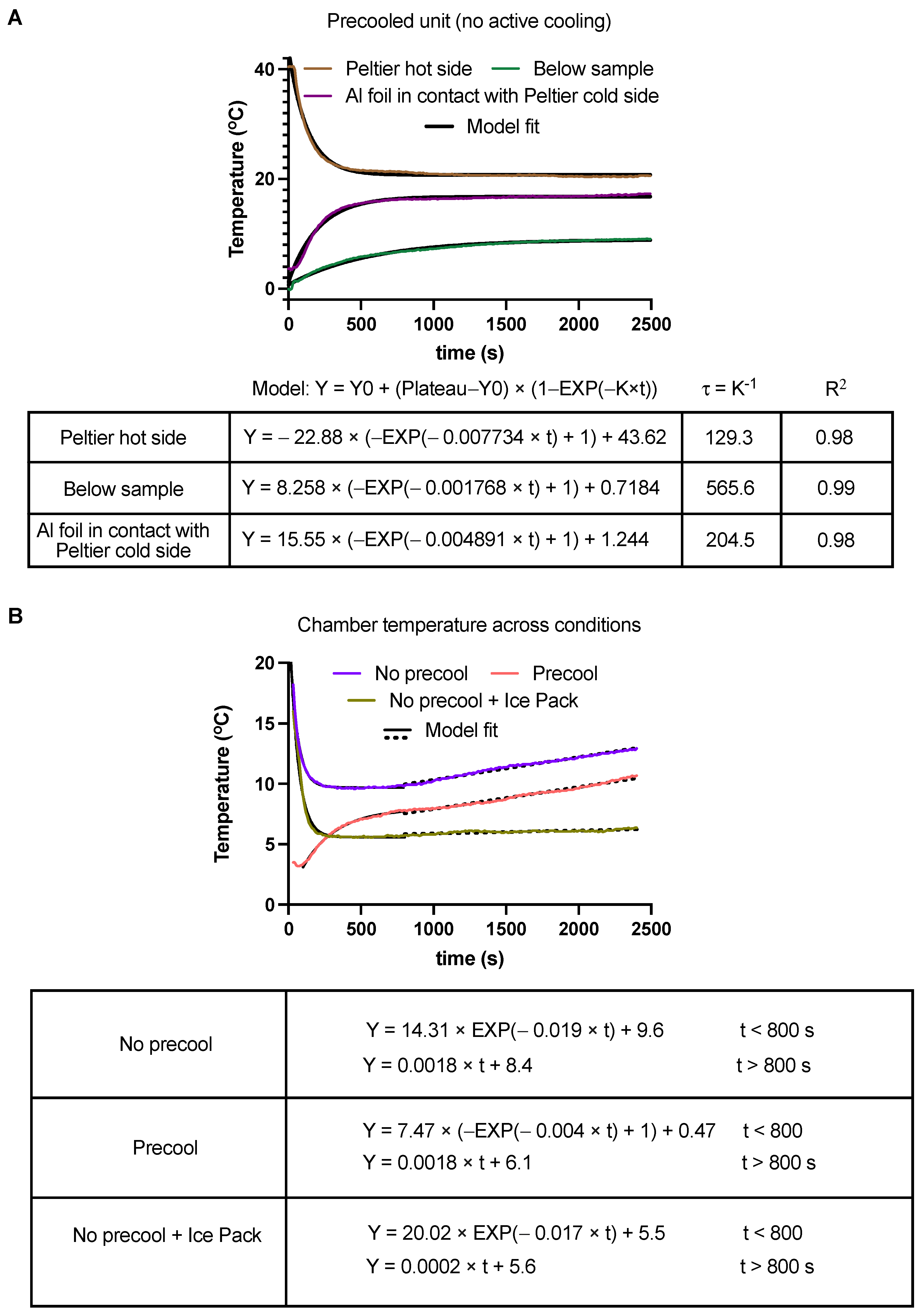
3.1. Performance with No Active Cooling

First, the performance of the cooling unit with no active cooling was evaluated to test the insulation capabilities of the system. The heat insulation performance of the cooling unit upon placement of a sample was evaluated under the following three conditions where no active cooling was used: (i) when the chamber was not precooled, (ii) when the chamber was not precooled but instead had a frozen ice pack to maintain a cool environment, and (iii) when the chamber was precooled to 4 °C prior to placing the sample. Precooling was performed by plugging in the Peltier and having it cool the chamber and a cool environment was simulated by putting the cooling module next to an AC vent.
Figure 2 shows temperature versus time for conditions where no precooling was performed. In the absence of an ice pack (Figure 2A), the temperature below the sample very quickly rises above 8 °C within around 500 s, i.e., the sample can be kept below the desired range of 2 °C to 8 °C (c.f. ICH guidelines for a refrigerator [34]) for only less than ~8 min. Consistent with no power being supplied to actively cool the system under these conditions, the temperature of the hot and cold sides of the Peltier also drops over time, suggesting that the sample is thermally equilibrating with the environment. When an ice pack was added to the chamber, mimicking current methods using cooling with ice packs and with no other form of active cooling, the temperature below the sample remained constant at nearly 8 °C for over 2500 s (Figure 2B). This suggests that to achieve and sustain a cool temperature below 8 °C within the chamber for longer times, some form of active cooling was needed. As described in the following sections, this was achieved with active Peltier cooling since it provides more direct control of the cooling performance across a wide range of conditions while being able to minimize the payload weight and cooling time/power consumption depending on the environmental conditions.
Next, whether precooling the chamber (e.g., prior to flight and loading the sample) with no other form of active cooling would improve the cooling performance of the system was explored. As expected, this approach, compared to no precooling, improved the cooling performance of the system enabling a temperature below the sample of less than 8 °C to be sustained for nearly 1500 s (~25 min) (Figure 3A). Further, the hot and cold sides of the Peltier recovered from their initial conditions of precooling to near-ambient conditions over the course of the experiment. To gain further insight into the timescales of heat transfer in the system, a lumped system analysis of the cooling unit was performed [40,41]. Specifically, denoting the temperature and temperature difference with the ambient by T and Δ T , and a characteristic heat transfer time constant by τ = K 1 = C / h A where C is the heat capacity, A is the surface area of heat transfer, and h is the heat transfer coefficient, a lumped system model for heat transfer in the system is given by:
d Δ T d t = K   T t .
This model predicts an exponential variation of temperature with time with an underlying timescale determined by the parameter τ (obtained as a fit to experimental data). Based on this model, exponential curves were fit to the temperature measurements in Figure 3A and an excellent model fit to data was obtained. The model fit suggested a characteristic time scale τ of around 565 s for heat loss from the sample. Interestingly, the temperature of the hot and cold sides of the Peltier also exhibited a similar exponential variation with time, but with shorter time scales.
Lastly, in Figure 3B, the chamber temperature measured just above the sample versus time across the three different conditions described in Figure 2A,B and Figure 3A is plotted. Consistent with the previous observations, the condition of ice pack cooling (with no precooling) achieved the lowest and most stable chamber temperature of around 6 °C over 2500 s, whereas the precooled chamber condition with no ice pack also sustained a temperature of below 8 °C for over 1500 s (~25 min). In addition, in order to quantitatively model the experimental data, lumped system model was used again to fit the chamber temperature data during the initial “rapid” heat transfer phase ( t < 800 s) wherein most of the heat exchange occurs between the cold sample and the surrounding environment within the chamber, followed by a linear fit for the “late” heat transfer phase ( t > 800 s) which is modeled as having a constant “leakage” heat transfer rate between the cooled chamber and the exterior environment. This model captured the data well, and importantly, suggested that in the absence of cooling (i.e., with no ice pack), the system has a constant heat loss rate of around 0.0018 °C/s after the initial rapid heat transfer phase in the beginning. In the presence of the ice pack, the rate dropped significantly to 0.0002 °C/s. Taken together, these data enabled us to characterize the baseline cooling/temperature insulation performance of the system and motivated the need for active cooling to achieve more robust cooling performance.

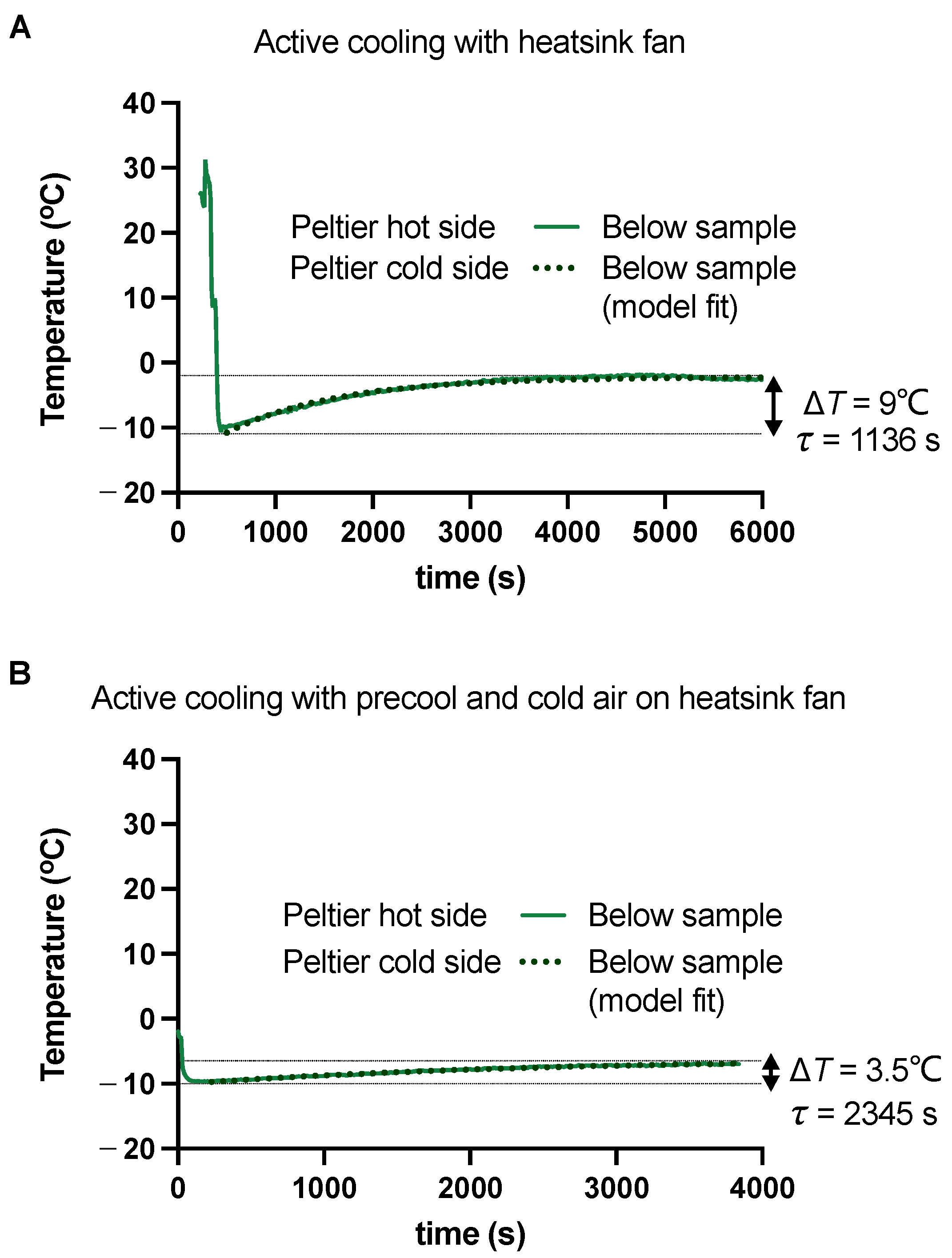
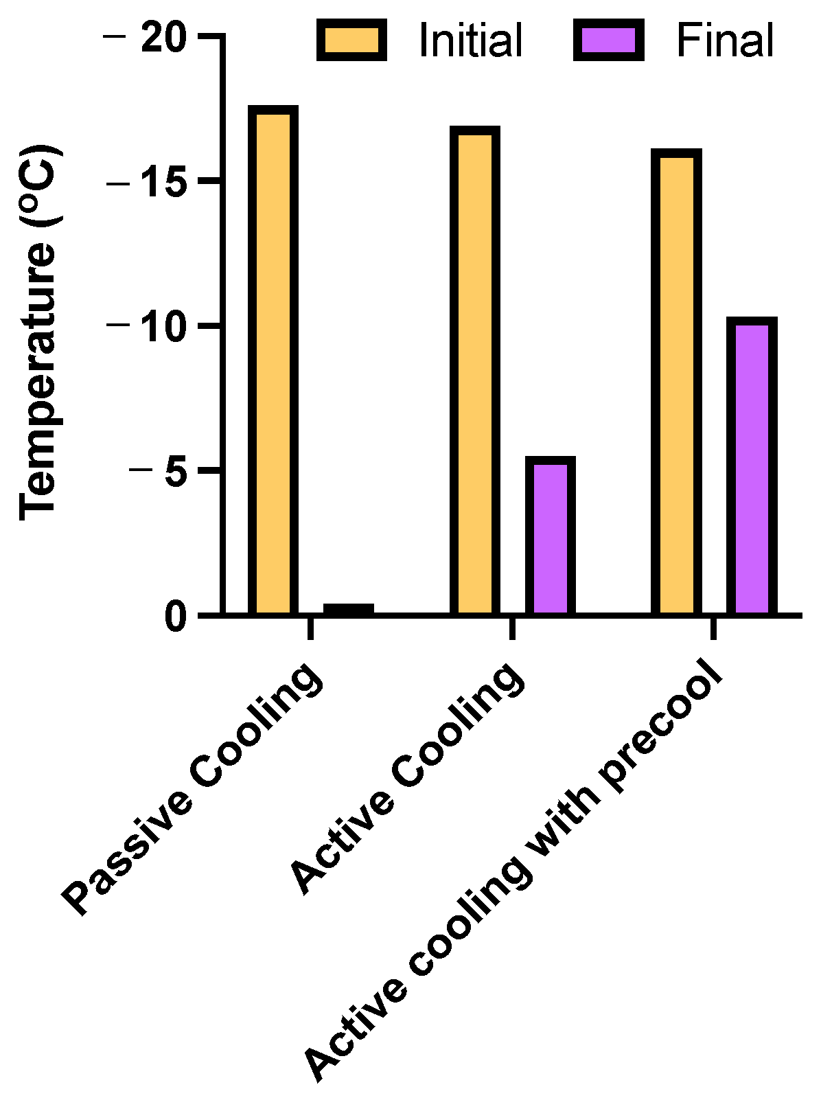
3.2. Performance with Active Cooling

Although passive cooling strategies described above are effective in maintaining temperatures in the 2 to 8 °C range, we hypothesized that achieving and maintaining freezing temperatures (i.e., below 0 °C) would likely require an active cooling mechanism. Such low-temperature requirements are frequently encountered in the context of handling and delivery of biologicals such as vaccines, medications, and human samples [9,11,18]. With this requirement in mind, the active cooling performance of the cooling unit which consisted of a single 12 V, 6 A thermoelectric cooler powered by an external battery was tested and evaluated. During operation, a fan mounted on the external heatsink (Figure 1D) was used to blow ambient air over the heatsink to mimic the scenario on a drone where the downwash of the propellers can be directed towards the on-board cooling unit to cool the external heatsink and enhance cooling performance.
Figure 4A shows temperature versus time measured on the hot and cold side of the Peltier, and at a location below the sample as an approximate measure of the chamber temperature. Similar to experiments in Section 3.1, frozen ice placed in a cup was used as the sample. Consistent with our hypothesis, sample temperatures below 0 °C (indicated by the solid green line) were achieved with active cooling. Specifically, upon placing the ice cup payload in the cooler, the temperature in the cooling unit dropped sharply from near-room temperature to around −10 °C, and thereafter over the course of 6000 s, the temperature increased and plateaued at −1 °C. To gain further quantitative insight into the cooling performance, a lumped system model (as described in Section 3.1) was used to fit the temperature data and found that the timescale τ for heat transfer in the presence of active cooling was 1136 s. Note that this value for active cooling is near twice the timescale obtained for the condition of no active cooling ( τ = 565 s) that is shown in Figure 3A, consistent with the expectation that active cooling delays heat transfer. Lastly, for these conditions, the heatsink of the Peltier remained close to the ambient temperature at 30 °C, while the temperature of the cold side dropped rapidly from ambient conditions upon turning on the cooler to around 0 °C and thereafter remained stable near 0 °C.
Next, the limits of active cooling performance achievable by the system were explored. We hypothesized that both precooling the chamber and actively cooling the heatsink by blowing cool air during operation will increase cooling performance. To test this, similar experimental conditions as in Figure 4A were used, but in addition, the system was precooled prior to loading the sample, and during operation, cool air was blown from the room’s AC vent on the hot side of the Peltier that mimicked cooler ambient conditions. As shown in Figure 4B, under these conditions, the temperature in the unit remained much more stable than the baseline active cooling conditions in Figure 4A. In particular, the Δ T rise in temperature within the unit was only around 3.5 °C in Figure 4B compared to 9 °C in Figure 4A. Further, using the lumped system model, the heat transfer timescale τ for the conditions in Figure 4B was observed to be 2345 s, which is more than twice the corresponding value in Figure 4A. Taken together, our data suggest that for a given active cooling system configuration, precooling the chamber and actively cooling the heatsink achieves a lower temperature rise in the chamber and delays heat transfer, both of which in turn, improve the cooling performance of the system. However, it is to be noted that the absolute minimum chamber temperatures achieved in Figure 4A,B are nearly the same, a value of around −10 °C. This value is above the freezer temperature range and below the refrigerator temperature range, as per the ICH guidelines [34]. We hypothesize that this lowest achievable temperature is primarily a function of the cooling capacity of the system, which is proportional to the total cooling surface area (i.e., depends on the number of Peltier cooler modules used) and the total supplied electrical charge. Therefore, the system is expected to achieve even lower temperatures upon the addition of more Peltier cooler modules, albeit with a tradeoff involving payload and on-board power requirements (see Section 3.4).
Lastly, passive versus active cooling operations for preserving the temperature of a frozen sample were directly compared in Figure 5 by measuring the temperature of frozen ice placed within the cooling unit for over 30 min under various conditions. As expected, active cooling with a precooled chamber resulted in the best performance with less than a 6 °C increase in sample temperature from its initial value, whereas simple active cooling without any precooling resulted in around 11 °C rise in sample temperature. Importantly, both these active cooling conditions preserved the sample at below-freezing temperatures throughout the experiment. However, in the absence of any active cooling, the temperature of the sample increased by 17 °C to a final value of 0 °C in 30 min. Therefore, consistent with our prior observations, our data suggest that in order to maintain the sample at freezing temperatures, active cooling mechanisms are necessary. On the contrary, if only temperatures that are typically used for refrigeration (i.e., between 0 to 8 °C) are desired for sample preservation starting from an initially frozen sample, then passive cooling/insulation methods will suffice.

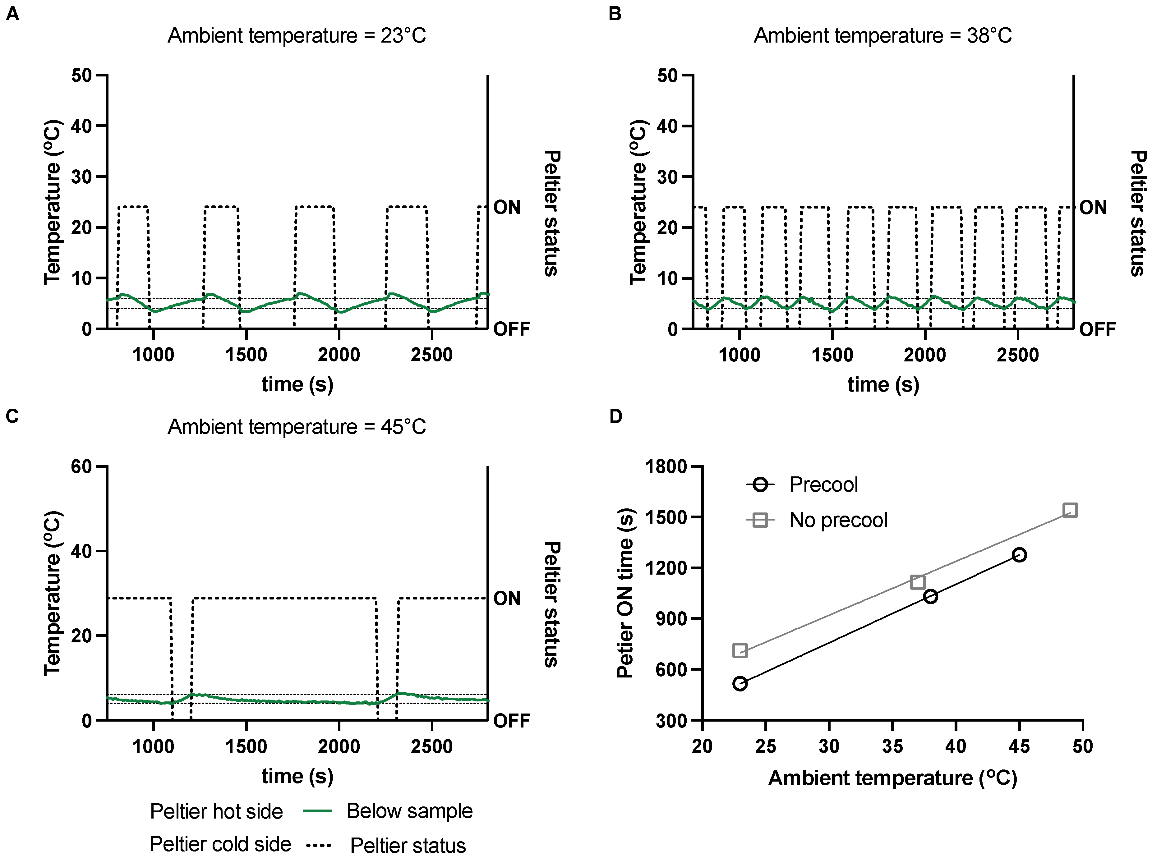
3.3. Feedback Control Operation for Precise Temperature Control and Reducing Power Consumption

So far, in this study, the baseline cooling performance of passive and active cooling mechanisms in the system has been studied and quantified. However, the operation methods described so far cannot precisely control and maintain the temperature within a preset target range, as would be typically required by most applications. Therefore, next, our attention was focused on developing and testing an operation method by which a target temperature range within the cooling unit can be precisely maintained, while also simultaneously reducing on-board power requirements for achieving target cooling performance. Specifically, the use of feedback-control operation was explored wherein the Peltier cooler was turned on when the temperature exceeded the target range, and the Peltier was turned off when the temperature dropped below the set range.
Here, this feedback-controlled active cooling scheme was tested for a desired target temperature range of 4 °C to 6 °C, which is the typical handling temperature range of many biological samples and falls within the refrigeration category as per the ICH guidelines [34]. Moreover, we hypothesized that the power requirements of the Peltier will depend on the ambient conditions. Therefore, the system was tested under three different simulated external environmental conditions varying between 23 °C and 45 °C (Figure 6A–C). Figure 6A–C show the temperature measured below the sample and at the hot and cold sides of the Peltier versus time, for average heatsink temperatures of 23 °C, 38 °C, and 45 °C. Also shown in the figure are the corresponding ON/OFF states of the Peltier. Here, the average heatsink temperatures were used as a measure of ambient conditions. These different ambient conditions were achieved by externally cooling the hot side of the Peltier to varying degrees as would typically occur in practice. Further, for these experiments, the chamber was precooled prior to testing. When the Peltier was ON, the power consumption was nearly constant at a value of around ~10 W.
As demonstrated in Figure 6A–C, the feedback-controlled operation scheme was successfully implemented to achieve the desired target temperature range of 4 °C to 6 °C in the unit across the different ambient conditions. Importantly, our experiments showed that the Peltier needed to be turned ON for longer durations when the ambient conditions were warmer (increasing ON duration going from Figure 6A to Figure 6C). This effect was quantified further by plotting the Peltier ON time versus the ambient conditions over the course of an 1800 s experiment in Figure 6D. A nearly linear trend was observed between the ambient temperature and the ON duration required for cooling within the range of conditions tested. Given the nearly constant power consumption of the Peltier when ON, data from Figure 6D therefore suggest that the total energy and charge consumption is directly proportional to the ambient temperature, within the range tested. Moreover, a longer operational/flight time would also imply a proportionally larger amount of energy and charge consumed to achieve target cooling performance (further explored in Section 3.4).
Taken together, the data in Figure 6 suggest that to maintain a desired sample temperature range within the cooler at warmer ambient conditions, the Peltier cooler would need to be turned on for a longer duration (i.e., longer duty cycles) thereby requiring more charge consumption/on-board power. Interestingly, this linear relationship was also observed when similar experiments were performed under conditions where the chamber was not precooled. In the latter case of no precooling, as expected, the Peltier needed to be turned ON for a longer duration to achieve the target temperature range for similar ambient conditions compared to when the chamber was precooled.

3.4. Battery Capacity and Battery Weight Requirements for Drone Applications

Here, our analysis is expanded further to quantify the battery weight (additional payload) and battery charge capacity required for drone-based delivery applications. As was previously noted in Section 3.3, warmer ambient conditions necessitate a longer ON time to achieve the desired cooling performance. How exactly does this translate to the required battery weight and charge capacity as a function of the ambient conditions? To answer this, the same target temperature range of 4 °C to 6 °C for a 30 min flight duration is considered, similar to that in Section 3.3.
First, it is to be noted that battery weight varies nearly linearly with the charge capacity of a battery. Shown in Figure 7A are values of battery weight (in grams) versus the charge capacity (in mAh) obtained from the manufacturer for a 3S LiPo battery, which is commonly used for drone applications. In our analysis below, the linear fit obtained in Figure 7A is used to relate the required battery weight and charge capacity for achieving the desired cooling performance. Shown in Figure 7B on the left axis is the required battery charge capacity versus ambient temperature, calculated based on the current drawn by the Peltier and the ON time data in Figure 6D. Similar to Figure 6D, Figure 7B shows that the required battery charge capacity increases linearly with the ambient temperature for both precooled and non-precooled initial chamber conditions. As expected, Figure 7B also shows that a higher charge capacity is required in the absence of precooling to achieve the same cooling performance under similar ambient conditions. Next, the required battery charge capacity data in Figure 7B and the relation between the battery charge capacity and battery weight in Figure 7A are used to relate the battery weight required versus ambient conditions (shown in the right axis of Figure 7B). Similar to the required charge capacity, the required battery weight increases linearly with the ambient temperature, and the required battery weight is higher for conditions where there is no precooling. Interestingly, Figure 7B also shows that both the battery weight and charge capacity required vary strongly with the ambient temperature conditions. For example, the required battery weight and battery charge capacity nearly double when the ambient temperature increases from around 25 °C to 50 °C. Our data therefore suggest that the on-board power requirements and payload can thus be strongly influenced by the ambient operating conditions for drone-based cold temperature delivery applications and that such considerations must be taken into account when planning drone missions.

4. Conclusions

In this study, a comprehensive experimental study aimed at the design, development, and characterization of a cooling unit for drone-based delivery of temperature-sensitive samples is presented. The cooling unit was custom-built using an expanded polystyrene box coupled with a thermoelectric Peltier cooler. Our main conclusions are as follows:
  • In the absence of active cooling, simple thermal insulation from the cooling unit was not sufficient to maintain cold temperatures below 8 °C for more than 10 min. Precooling the chamber prior to operation or inclusion of an ice pack improved performance. However, neither of these passive cooling approaches enabled achieving temperatures below freezing and precise temperature control, thereby motivating the need for active cooling.
  • Using the thermoelectric cooler, temperatures as low as −10 °C were achieved and below-freezing temperatures were sustained. As with passive cooling, precooling the chamber prior to operation improved the performance of the active cooling method.
  • Using a lumped system model, the timescale of heat transfer in the system under different operating modes was characterized. Our data suggested that the timescale over which heat dissipation occurred nearly doubled when active cooling was used compared to passive cooling. The timescale increased further when the chamber was precooled and a cooler external ambient condition was presented.
  • Upon characterization of the baseline active cooling performance of the system, our work focused on the demonstration of a practical operation scenario of the cooling system to maintain a cooling temperature within the range of 4 °C to 6 °C. To achieve this, a feedback control operation of the cooling unit was used and demonstrated, and the performance at different ambient conditions was characterized. Our observations suggested that the thermoelectric cooler needed to be turned ON for longer durations (and therefore, required higher charge capacity) to meet performance goals when the ambient conditions were warmer.
  • To translate performance into system requirements, the required battery weight was related to the battery charging capacity using a linear relation based on manufacturer specifications. Our data suggested that the operation of the system at warmer ambient temperatures would also likely require higher battery weight as an additional payload, resulting from the need for additional charge capacity to achieve target cooling performance.
Overall, this study presents a systematic analysis of the design, features, and characterization of onboard cooling systems tailored for temperature-sensitive sample delivery using UAVs and highlights several important design considerations that need to be taken into account for such systems. Further research is needed to expand the design parameters of the cooling unit presented in this study for operation under diverse and dynamic conditions of drone flight such as varying altitudes and structural vibration, and for much longer flight durations (beyond ~30–50 min) and varying drone weights.

Author Contributions

Conceptualization, G.P. and L.P.; methodology, G.P. and L.P.; validation, G.P. and L.P.; formal analysis, G.P., L.P. and A.R.; investigation, G.P. and L.P.; resources, G.P. and L.P.; writing—original draft preparation, G.P., L.P. and A.R.; writing—review and editing, G.P., L.P. and A.R. All authors have read and agreed to the published version of the manuscript.

Funding

This research received no external funding.

Data Availability Statement

All data is included in the manuscript.

Conflicts of Interest

The authors declare no conflicts of interest.

Appendix A

Presented here is a table that summarizes the advantages and disadvantages of various cooling strategies applicable for UAV-based applications in comparison with the thermoelectric-based cooling system developed in this study.
Table A1. Comparison of the thermoelectric cooling unit developed in this study with various on-board cooling strategies for temperature-sensitive sample delivery and transportation using UAVs.
MethodAdvantagesDisadvantagesBenefit of Our MethodRefs.
Dry Ice
-
Effective at maintaining low temperatures (−80 °C)
-
Inexpensive (<$2 per lb.)
-
Requires frequent replenishment
-
Safety concerns (CO2 gas buildup)
-
Regulatory challenges (hazardous material)
-
Limited to short-duration flights (2–3 h)
-
Significant weight limits payload capacity (500 g−1 kg)
-
Not used due to impracticality in off-grid locations
-
Safety and regulatory concerns avoided
[16,25,26]
Conditioned Ice Packs
-
Widely available
-
Simple to use
-
Heavy (500 g−1 kg per pack), occupies >1/3 of payload capacity
-
Reduces UAV range by up to 30%
-
No precise temperature control (fluctuations between 0 °C and 15 °C)
-
Lightweight design (<300 g)
-
Precise temperature control with active feedback (±2 °C)
-
Reduced payload impact, ability to enhance range by 20–30%
[17,18,22]
Refrigerated containers
-
Provides active cooling
-
Can maintain a wide range of temperatures (−20 °C to +4 °C)
-
Heavy and bulky (3–5 kg)
-
High power consumption (50–100 W)
-
Reduces UAV range significantly (up to 50%)
-
Lightweight thermoelectric cooling (<300 g)
-
Energy-efficient operation (10–15 W)
[10,11,16]
Thermoelectric coolers
-
Solid-state, lightweight (<200 g)
-
Effective for moderate cooling needs (down to 12 °C)
-
Power consumption can be high for long durations (20–30 W)
-
Typically limited to moderate cooling ranges (e.g., 12 °C)
-
Advanced thermoelectric cooling to achieve −10 °C
-
Dynamic feedback control optimizes power use
-
Precise temperature control with active feedback (±2 °C)
-
Maintains precise temperature range (2 °C to 8 °C) with lower power consumption (10–15 W)
[29,31,33] and this study.

Appendix B

Listed below are the specifications of the thermoelectric cooler module used in this work. The specifications are collated from the data sheet of the manufacturer and other published studies [42,43,44,45,46].
Table A2. Specifications of the thermoelectric cooler TEC1-12706 used in this study.
SpecificationValue
Hot side temperature30 °C
Δ T m a x 65 °C
Maximum heat transfer Q m a x 51 W
Current I m a x 6 A
Voltage V m a x 15.4 V
Resistance2.07 Ω
Thermal conductivity1.5 Wm−1K−1
Efficiency rating13–77%

References

  1. Zaffran, M.; Vandelaer, J.; Kristensen, D.; Melgaard, B.; Yadav, P.; Antwi-Agyei, K.O.; Lasher, H. The Imperative for Stronger Vaccine Supply and Logistics Systems. Vaccine 2013, 31, B73–B80. [Google Scholar] [CrossRef] [PubMed]
  2. Mohsan, S.A.H.; Khan, M.A.; Noor, F.; Ullah, I.; Alsharif, M.H. Towards the Unmanned Aerial Vehicles (UAVs): A Comprehensive Review. Drones 2022, 6, 147. [Google Scholar] [CrossRef]
  3. Tsouros, D.C.; Bibi, S.; Sarigiannidis, P.G. A Review on UAV-Based Applications for Precision Agriculture. Information 2019, 10, 349. [Google Scholar] [CrossRef]
  4. Mohd Noor, N.; Abdullah, A.; Hashim, M. Remote Sensing UAV/Drones and Its Applications for Urban Areas: A Review. IOP Conf. Ser. Earth Environ. Sci. 2018, 169, 012003. [Google Scholar] [CrossRef]
  5. Chan, K.W.; Nirmal, U.; Cheaw, W.G. Progress on Drone Technology and Their Applications: A Comprehensive Review. AIP Conf. Proc. 2018, 2030, 20308. [Google Scholar] [CrossRef]
  6. Dhote, J.; Limbourg, S. Designing Unmanned Aerial Vehicle Networks for Biological Material Transportation—The Case of Brussels. Comput. Ind. Eng. 2020, 148, 106652. [Google Scholar] [CrossRef]
  7. Hii, M.; Courtney, P.; Royall, P. An Evaluation of the Delivery of Medicines Using Drones. Drones 2019, 3, 52. [Google Scholar] [CrossRef]
  8. Amukele, T.K.; Sokoll, L.J.; Pepper, D.; Howard, D.P.; Street, J. Can Unmanned Aerial Systems (Drones) Be Used for the Routine Transport of Chemistry, Hematology, and Coagulation Laboratory Specimens? PLoS ONE 2015, 10, e0134020. [Google Scholar] [CrossRef]
  9. Geronel, R.S.; Begnini, G.R.; Botez, R.M.; Bueno, D.D. An Overview on the Use of Unmanned Aerial Vehicles for Medical Product Transportation: Flight Dynamics and Vibration Issues. J. Braz. Soc. Mech. Sci. Eng. 2022, 44, 349. [Google Scholar] [CrossRef]
  10. Theobald, K.; Zhu, W.; Waters, T.; Cherrett, T.; Oakey, A.; Royall, P.G. Stability of Medicines Transported by Cargo Drones: Investigating the Effects of Vibration from Multi-Stage Flight. Drones 2023, 7, 658. [Google Scholar] [CrossRef]
  11. Amukele, T.; Ness, P.M.; Tobian, A.A.R.; Boyd, J.; Street, J. Drone Transportation of Blood Products. Transfusion 2017, 57, 582–588. [Google Scholar] [CrossRef]
  12. Amukele, T.K.; Hernandez, J.; Snozek, C.L.; Wyatt, R.G.; Douglas, M.; Amini, R.; Street, J. Drone Transport of Chemistry and Hematology Samples Over Long Distances. Am. J. Clin. Pathol. 2017, 148, 427–435. [Google Scholar] [CrossRef]
  13. Prager, A.; Gu, K. Delivery of Temperature-Sensitive Items. U.S. Patent 11,410,114, 9 August 2022. [Google Scholar]
  14. Mangelsen, J.; Merchant, R. Aerial Delivery Packages. U.S. Patent 17/426,256, 24 March 2022. [Google Scholar]
  15. Cattin, M.; Jonnalagedda, S.; Makohliso, S.; Schönenberger, K. The Status of Refrigeration Solutions for Last Mile Vaccine Delivery in Low-Income Settings. Vaccine X 2022, 11, 100184. [Google Scholar] [CrossRef] [PubMed]
  16. Ghelichi, Z.; Gentili, M.; Mirchandani, P.B. Logistics for a Fleet of Drones for Medical Item Delivery: A Case Study for Louisville, KY. Comput. Oper. Res. 2021, 135, 105443. [Google Scholar] [CrossRef]
  17. Sham, R.; Siau, C.S.; Tan, S.; Kiu, D.C.; Sabhi, H.; Thew, H.Z.; Selvachandran, G.; Quek, S.G.; Ahmad, N.; Ramli, M.H.M. Drone Usage for Medicine and Vaccine Delivery during the COVID-19 Pandemic: Attitude of Health Care Workers in Rural Medical Centres. Drones 2022, 6, 109. [Google Scholar] [CrossRef]
  18. De Silvestri, S.; Capasso, P.J.; Gargiulo, A.; Molinari, S.; Sanna, A. Challenges for the Routine Application of Drones in Healthcare: A Scoping Review. Drones 2023, 7, 685. [Google Scholar] [CrossRef]
  19. De Silvestri, S.; Pagliarani, M.; Tomasello, F.; Trojaniello, D.; Sanna, A. Design of a Service for Hospital Internal Transport of Urgent Pharmaceuticals via Drones. Drones 2022, 6, 70. [Google Scholar] [CrossRef]
  20. Niglio, F.; Comite, P.; Cannas, A.; Pirri, A.; Tortora, G. Preliminary Clinical Validation of a Drone-Based Delivery System in Urban Scenarios Using a Smart Capsule for Blood. Drones 2022, 6, 195. [Google Scholar] [CrossRef]
  21. Kostin, A.S.; Silin, Y.A. Development of an Insulated Container for the Implementation of the Delivery of Special Cargo Using an Unmanned Aerial System. In Proceedings of the 2022 Wave Electronics and its Application in Information and Telecommunication Systems (WECONF), St. Petersburg, Russia, 30 May–3 June 2022; IEEE: Piscataway, NJ, USA, 2022; pp. 1–4. [Google Scholar]
  22. Liu, R.; Pitruzzello, G.; Rosa, M.; Battisti, A.; Cerri, C.; Tortora, G. Towards an Innovative Sensor in Smart Capsule for Aerial Drones for Blood and Blood Component Delivery. Micromachines 2022, 13, 1664. [Google Scholar] [CrossRef]
  23. Peltier, G.C.; Meledeo, M.A. The Impact of Delivery by a Fixed-Wing, Sling-Launched Unmanned Aerial Vehicle on the Hematologic Function of Whole Blood. J. Trauma Acute Care Surg. 2023, 95, S152–S156. [Google Scholar] [CrossRef]
  24. Ganesan, G.S.; Mokayef, M. Multi-Purpose Medical Drone for the Use in Pandemic Situation. In Proceedings of the 2021 IEEE Microwave Theory and Techniques in Wireless Communications (MTTW), Riga, Latvia, 7–8 October 2021; IEEE: Piscataway, NJ, USA, 2021; pp. 188–192. [Google Scholar]
  25. Blount, W. Temperature Controlled Transport of Vaccines by Drone in Developing Countries; Georgia Institute of Technology: Atlanta, GA, USA, 2018. [Google Scholar]
  26. Saponi, M.; Borboni, A.; Adamini, R.; Faglia, R.; Amici, C. Embedded Payload Solutions in UAVs for Medium and Small Package Delivery. Machines 2022, 10, 737. [Google Scholar] [CrossRef]
  27. Sykes, C. Time-and Temperature-Controlled Transport: Supply Chain Challenges and Solutions. Pharm. Ther. 2018, 43, 154. [Google Scholar]
  28. Buidin, T.I.C.; Mariasiu, F. Battery Thermal Management Systems: Current Status and Design Approach of Cooling Technologies. Energies 2021, 14, 4879. [Google Scholar] [CrossRef]
  29. Enescu, D.; Virjoghe, E.O. A Review on Thermoelectric Cooling Parameters and Performance. Renew. Sustain. Energy Rev. 2014, 38, 903–916. [Google Scholar] [CrossRef]
  30. Sharma, S.; Dwivedi, V.K.; Pandit, S.N. A Review of Thermoelectric Devices for Cooling Applications. Int. J. Green Energy 2014, 11, 899–909. [Google Scholar] [CrossRef]
  31. Ivanov, K.; Belovski, I.; Aleksandrov, A. Design, Building and Study of a Small-Size Portable Thermoelectric Refrigerator for Vaccines. In Proceedings of the 2021 17th Conference on Electrical Machines, Drives and Power Systems (ELMA), Sofia, Bulgaria, 1–4 July 2021; IEEE: Piscataway, NJ, USA, 2021; pp. 1–4. [Google Scholar]
  32. Pamula, G.; Pamula, L.; Pamula, V. Mini Freezer-Equipped Drone for Transporting Biological Materials and Method of Using Same. U.S. Patent 18/213,149, 19 October 2023. [Google Scholar]
  33. Sankaran, V.; Alagumariappan, P.; Esakki, B.; Choi, J.; Hameed, M.T.K.S.; Pittu, P.S.K.R. Devising an Internet of Things-Based Healthcare Medical Container for the Transportation of Organs and Healthcare Products Using Unmanned Aerial Vehicles. In Proceedings of the ECSA 2023, Online, 15–30 November 2023; MDPI: Basel Switzerland, 2023; Volume 58, p. 16. [Google Scholar]
  34. International Council for Harmonisation International Conference on Harmonisation (ICH). Guidance for Industry: Q1A(R2) Stability Testing of New Drug Substances and Products. ICH Harmon. Tripart. Guidel. 2003, 4, 24. [Google Scholar]
  35. Amicone, D.; Cannas, A.; Marci, A.; Tortora, G. A Smart Capsule Equipped with Artificial Intelligence for Autonomous Delivery of Medical Material through Drones. Appl. Sci. 2021, 11, 7976. [Google Scholar] [CrossRef]
  36. Lee, S.; Kwon, Y. Development of Drone Cargo Bay with Real-Time Temperature Control. World J. Eng. Technol. 2019, 07, 612–621. [Google Scholar] [CrossRef]
  37. Available online: https://www.Updwg.Org/Md3/?Action=filter (accessed on 1 April 2024).
  38. Swoop Aero. Available online: https://swoop.Aero (accessed on 1 April 2024).
  39. Zipline. Available online: https://www.Flyzipline.com (accessed on 1 April 2024).
  40. Nellis, G.; Klein, S. Heat Transfer; Cambridge University Press: Cambridge, UK, 2008. [Google Scholar]
  41. Sidebotham, G. Heat Transfer Modeling; Springer: Cham, Switzerland, 2015. [Google Scholar]
  42. Peter, A.J.; Balaji, D.; Gowrishankar, D. Waste Heat Energy Harvesting Using Thermo Electric Generator. IOSR J. Eng. 2013, 3, 1–4. [Google Scholar] [CrossRef]
  43. Harun, M.H.; Azmi, M.W.N.; Aras, M.S.M.; Azlan, U.A.A.; Azahar, A.H.; Annuar, K.A.M.; Halim, M.F.M.A.; Yaakub, M.F.; Abidin, A.F.Z. A Study on the Potential of Peltier in Generating Electricity Using Heat Loss at Engine and Exhaust Vehicle. J. Adv. Res. Fluid Mech. Therm. Sci. 2018, 49, 77–84. [Google Scholar]
  44. Sari, H.N.; Arsana, I.M.; Bramantyo, K.U.; Cholik, M.; Kurniawan, W.D.; Wijanarko, D.V. Performance Analysis of Electric Coolers TEC1-12706 and TEC1-12715 with Heatsinks at Semi-Conductor Cooler Boxes. In Proceedings of the International Joint Conference on Science and Engineering 2022 (IJCSE 2022), Surabaya, Indonesia, 10–11 September 2022; Agustin, H.P., De Oliveira, A.M., Anistyasari, Y., Ueda, K., Wardhono, A., Rahayu, I.A.T., Eds.; Atlantis Press International BV: Dordrecht, The Netherlands, 2022; pp. 281–292, ISBN 978-94-6463-099-2. [Google Scholar]
  45. Wang, C.; Calderón, C.; Wang, Y.D. An Experimental Study of a Thermoelectric Heat Exchange Module for Domestic Space Heating. Energy Build. 2017, 145, 1–21. [Google Scholar] [CrossRef]
  46. Hebei IT Co., Ltd. Thermoelectric Cooler TEC1-12706; Hebei IT Co., Ltd.: Shanghai, China, 2017; Volume 31, p. 2017. [Google Scholar]
Figure 1. Images of the small, custom-built expanded polystyrene (XPS) cooling unit for drone applications. (A) Stack of a Peltier cooler and aluminum blocks used to fill a cut side hole of the XPS box and integrate the thermoelectric cooler with the unit. (B) Top plate to create a tight seal for the inner chamber. (C) Frozen ice in a cup was used as the sample. (D) Fully assembled cooling unit with a heat sink. (E) Placement of thermocouples for real-time temperature monitoring. (F) Different ambient conditions were simulated by blowing cool air over the exterior of the unit/heatsink.
Drones 08 00270 g001
Figure 2. Baseline passive cooling performance of the system. Measured temperature versus time for (A) No precooling of the chamber prior to loading the sample, and (B) when an ice pack was additionally included within the chamber under similar conditions as (A). The rapid drop in temperatures in (B) for the initial ~100 s is attributed to chamber conditioning resulting from the preconditioned ice pack.
Drones 08 00270 g002
Figure 3. Quantitative modeling and heat transfer characterization of the cooling system. (A) Temperature measurements versus time when the chamber was precooled prior to loading the sample. Also shown are fits based on the lumped system model. (B) Chamber temperature measurements versus time across various passive cooling strategies, along with model fit.
Drones 08 00270 g003
Figure 4. Baseline active cooling performance of the system with the thermoelectric cooler ON during the entire duration of the experiment. Measured temperature versus time for (A) no precooled chamber, and (B) when the chamber was precooled prior to loading sample and minimal heat was removed from the hot side by blowing cool air using an external fan mounted on the heatsink. Lumped system model fits are shown in dashed lines, and the maximum temperature change over the experimental duration is indicated.
Drones 08 00270 g004
Figure 5. Direct comparison of active and passive cooling strategies using the cooling unit. Shown here are the initial ( t = 0 min) and final ( t = 30 min) temperature measurements of a frozen ice sample placed within the cooling unit.
Drones 08 00270 g005
Figure 6. Demonstration and characterization of feedback-controlled active cooling performance of the system. Measured temperature and Peltier ON/OFF status versus time are shown for feedback-controlled operation at simulated ambient temperatures of (A) 23 °C, (B) 38 °C, and (C) 45 °C. For these experiments, the chamber was precooled prior to sample placement, and a target temperature range of 4 °C to 6 °C was demonstrated. The thermoelectric cooler was toggled between ON/OFF states during operations. The corresponding Peltier ON time for a 30 min total operation to achieve the target temperature range versus varying ambient conditions is plotted in (D). Also shown in (D) are data when the chamber was not precooled prior to sample loading. A linear regression, indicated by solid lines in (D), captures the relation between Peltier ON time versus ambient temperature.
Drones 08 00270 g006
Figure 7. Battery requirements to achieve target cooling performance. (A) Battery weight versus the charge capacity of a 3S LiPo battery using data obtained from the manufacturer. (B) Calculated battery capacity and estimated battery weight (in the form of additional payload) required to achieve target cooling performance of 4 °C to 6 °C for a 30 min as a function of ambient temperature, for both initially precooled and no precooled chamber conditions. A linear regression represents the trends in (B) well.
Drones 08 00270 g007
Disclaimer/Publisher’s Note: The statements, opinions and data contained in all publications are solely those of the individual author(s) and contributor(s) and not of MDPI and/or the editor(s). MDPI and/or the editor(s) disclaim responsibility for any injury to people or property resulting from any ideas, methods, instructions or products referred to in the content.

