Article

Resource Allocation for UAV-RIS-Assisted NOMA-Based URLLC Systems

1
School of Communications and Information Engineering, Chongqing University of Posts and Telecommunications, Chongqing 400065, China
2
School of Intelligent Engineering, Shandong Management University, Jinan 250100, China
3
School of Information Science and Technology, Chengdu University of Technology, Chengdu 200433, China
4
School of Communication and Information Engineering, University of Electronic Science and Technology of China, Chengdu 611731, China
5
School of Information Science and Engineering, Shandong University, Qingdao 266237, China
*
Author to whom correspondence should be addressed.
Drones 2024, 8(7), 301; https://doi.org/10.3390/drones8070301
Submission received: 13 May 2024 / Revised: 4 July 2024 / Accepted: 5 July 2024 / Published: 7 July 2024
(This article belongs to the Special Issue Space–Air–Ground Integrated Networks for 6G)

Abstract

:
This work focuses on maximizing the sum rate of ultra-reliable low-latency communication (URLLC) systems by leveraging unmanned aerial vehicle-mounted reconfigurable intelligent surface (UAV-RIS) to provide short packet services for users based on the non-orthogonal multiple access (NOMA) protocol. To optimize the sum rate of system, a joint optimization is performed with respect to the power allocation, UAV position, decoding order, and RIS phase shifts. As the original problem is a non-convex integer optimization problem, it is challenging to obtain the optimal solution. Therefore, approximate solutions are derived using successive convex approximation (SCA), slack variables, and penalty-based methods. The simulation results demonstrate the superiority of the proposed resource allocation algorithm compared with the benchmark algorithm with orthogonal multiple access (OMA) scheme. In addition, this work emphasizes the performance gap between the proposed communication system and the traditional Shannon communication system in terms of throughput and the performance capacity sacrificed to achieve lower latency.

1. Introduction

In today’s increasingly interconnected world, there is a growing demand for efficient, reliable, and low-latency communications technologies. Modern communication systems must be able to transmit large amounts of data in real-time to support a wide range of applications, including instant messaging, intelligent transportation, telemedicine, etc. Ultra-reliable low-latency communication (URLLC) technology has emerged, providing an innovative solution to meet these demands. URLLC is considered one of the three core services to meet the upcoming needs of B5G networks. Traditional communication networks may experience high latency or unreliable performance in high loads, harsh environments, or equipment failures. However, URLLC technology can overcome these issues by adopting new design ideas, protocols, and algorithms to ensure the real-time and reliability of the communication process [1].

1.1. Related Work

In addition to its wide application in the military, aviation, and transportation fields, unmanned aerial vehicles (UAVs) also play a vital role in communications. By carrying advanced communication equipment and sensors, UAVs can be quickly deployed in the air and support communication, especially in remote areas and emergencies. Compared to traditional ground communication, the advantage of UAV communication lies in its higher controllability, which enables high-speed and reliable transmission under line-of-sight (LoS) links while optimizing its position to improve communication performance [2]. In [3], the authors investigated the UAV-assisted backscatter system. In order to ensure fairness among users, joint optimization of UAV trajectory, power allocation, and user scheduling is used to maximize the minimum user’s rate. The authors in [4] proposed a low-complexity inter-cell interference coordination algorithm by deploying single and multiple UAVs in a cellular environment to promote URLLC services using cognitive radio. In [5], the authors used UAVs as relays to transmit short data packets between the base station (BS) and multiple mobile robots. The packet length, power allocation, and UAV position were optimized to minimize the average overall decoding error. The resource allocation problem of a UAV-assisted URLLC system was investigated in [6], where the UAV was used as a decode-and-forward relay. By jointly optimizing the trajectory of the UAV and block length, the sum rate of the system was maximized. The authors in [7] investigated the user-centric cell-free massive multiple-input multiple-output (MIMO) system where a UAV provides URLLC services to ground users. Ref. [8] proposed a UAV as the relay assisted data collection and transmission scheme. To maximize energy efficiency, the user scheduling, flight duration, and UAV trajectory are jointly optimized during the data collection phase. During the data transmission phase, the packet length and UAV transmission power are jointly optimized to maximize the secrecy rate.
The inspiration for reconfigurable intelligent surface (RIS) comes from the structures with adaptive reflection characteristics in nature. By applying these properties to artificial materials and devices, dynamic adjustments in performance can be achieved, bringing many advantages to wireless communication systems. In traditional wireless communication, obstacles may lead to reduced signal quality and limited coverage, and the introduction of RIS can solve these problems by adjusting the propagation path and transmission direction of the signal to optimize the communication effect [9,10] . Currently, some literature has studied the application of RIS to improve the throughput and energy efficiency of URLLC systems. In [11], the authors proposed RIS-assisted full-duplex (FD) URLLC systems based on NOMA to achieve sum-rate maximization. To meet the reliability, delay, and minimum rate requirements, the total throughput of the system is maximized by jointly optimizing RIS phase shifts and power allocation under finite block length coding. In [12], the authors maximized the finite block length rate through deep reinforcement learning in a non-ideal RIS-assisted URLLC system. The authors in [13] considered the downlink RIS-assisted URLLC system, where the BS served multiple single-antenna users under the finite block length. The authors in [14] adopted the RSMA protocol to investigate the fairness resource allocation problem of the RIS-assisted multi-cell URLLC system. Aiming at the problems of equipment density and easy obstruction of wireless signals in factory automation scenarios, the authors in [15] proposed to create an alternative transmission link by deploying RIS to increase communication reliability. Furthermore, RIS can intelligently adjust the channel quality to reduce the eavesdropping rate, thereby increasing the rate of legitimate users. In [16], the authors investigated the RIS-assisted multi-input single-output symbiotic radio system with short packet services and developed a new framework based on deep reinforcement learning to solve the problem of maximizing energy efficiency.
Due to the significant path loss and high construction costs of traditional ground communication systems, they can no longer meet the diverse communication needs of contemporary society, such as long-distance communication and military operations. Hence, balancing cost reduction and communication quality improvement remains a significant challenge. The combination of the UAV and RIS technology can make up for this shortfall. Integrating RIS and UAV technology into URLLC systems can improve communication quality and system capacity to meet the growing communication needs of today’s society. There are two main integration methods of UAV and RIS: one is to use UAV as the air base station and RIS as the static relay and realize efficient and reliable wireless communication through UAV mobility and RIS intelligent beamforming. Another approach is directly installing UAV-mounted RIS (UAV-RIS) to form relays, enabling more flexible and efficient wireless communication through UAV flight control and RIS beamforming. Both of these methods can improve the performance and security of wireless communication and have broad application prospects. In [17], the authors proposed the UAV-RIS-enhanced mobile edge computing system, which uses the double-deep Q-network to jointly optimize UAV trajectory, user scheduling, and RIS phase shifts to maximize the system energy efficiency. In [18], the authors investigated secure multi-user communication in RIS-enhanced UAV systems with transmitters that have hardware impairments. Based on outdated and imperfect channel states, the authors in [19] investigated a multi-RIS assisted UAV downlink communication system. Considering the energy consumption of UAVs, the authors in [20] proposed the energy efficiency maximization of RIS-assisted UAV mobile edge computing systems based on NOMA protocol. In [21], the authors investigated the UAV-RIS-assisted downlink communication system. In addition to RIS passively forwarding base station signals, UAV helps BS transmit information to users in decoding and forwarding mode. In the presence of eavesdroppers, the authors in [22] investigated a secure transmission framework aided by both full-duplex UAV and RIS. This framework leverages a joint optimization approach of the UAV’s trajectory, RIS’s phase shifts, and user transmit powers, with the objective of maximizing the secrecy rate under the worst-case scenario. The authors in [23] investigated the average secrecy rate maximization problem for an IRS-assisted UAV network. An iteration algorithm was proposed by jointly optimizing the trajectory of UAV, transmit beamforming, and phase shift. The authors in [24] proposed the sum rate maximization problem for UAV-RIS-assisted the cell-free massive multiple-input multiple-output systems.

1.2. Contributions and Novelty

However, the above literature on RIS and UAV integration needs to consider short-packet communication scenarios, especially in complex communication environments where meeting users’ quality of service (QoS) requirements is challenging. Although UAV-RIS-assisted URLLC systems have the potential to revolutionize wireless networks, providing more efficient, reliable, and innovative solutions for future communication networks, these systems are still in their early stages of development. In [25], joint optimization of UAV placement, RIS phase shifts, and block length were adopted to minimize the overall bit error rate. Despite deploying RIS on walls, it can still cause signal blockage. Conversely, in [26,27], the authors employed a UAV-RIS, enhancing the flexibility of the RIS. Ref. [26] analyzed the performance of the UAV-RIS-assisted short-packet communication system but did not consider resource allocation and multi-user situations. Ref. [27] investigated UAV-RIS assisted URLLC system and rate maximization problem under imperfect SIC, but approximates the channel dispersion of the short packet part. Additionally, ref. [28] investigated an air RIS-assisted NOMA communication system, but did not consider short packet communication and multiple users. Different from [25,26,28], we investigate the problem of maximizing the sum rate of the UAV-RIS-assisted URLLC system. The key contributions of this work are as follows: Firstly, to address a broader range of real-world scenarios, we consider resource allocation for UAV-RIS-assisted URLLC systems based on the NOMA protocol. By jointly optimizing power allocation, RIS phase shifts, UAV position, and NOMA decoding order, the sum rate of the systems is maximized. Secondly, to solve a non-convex optimization problem, we employ techniques such as successive convex approximation (SCA), penalty-based, and slack variables to obtain the solutions. Finally, simulation results validate the superiority of the proposed algorithm and illustrate the performance gap between the proposed communication system and the traditional Shannon capacity in achieving high reliability and low delay.

2. System Model

As shown in Figure 1, the system model consists of K single-antenna users indexed by set K = { 1 , , K } , a UAV-RIS, and a single-antenna ground BS. Suppose that the coordinates of the BS and the k-th user are respectively expressed as w s = x s , y s T and w k = x k , y k T ,   k K . The horizontal coordinate of the UAV is q = [ x , y , z ] T . The phase shift matrix on the diagonal of the RIS is expressed as Ψ = diag e j θ 1 , e j θ 2 , , e j θ M , where M denotes the number of reflective elements.
When the UAV-RIS height is high enough, the ground-to-air (G2A) channel model adopts the LoS probability path loss model. The LoS probability between ground nodes and UAV-RIS is given by [29]:
P L o S = 1 1 + l 1 exp l 2 θ i j l 1 , i j { B U , U k }
where l 1 and l 2 are constants related to the environment. θ i j denotes the elevation angle from the node i to j, and B U and U k represent from the BS to the UAV and from the UAV to the k-th user. The constraint condition that the LoS probability is greater than the threshold value is introduced in the UAV position optimization to ensure the high LoS probability of the UAV to the ground node. According to [23], we adopt the high G2A LoS dominant channel model. Therefore, the channel power gain from the BS to the UAV-RIS and from UAV-RIS to the k-th user are given by:
g B U = ρ 0 d B U 2
g U k = ρ 0 d U k 2
where ρ 0 denote the channel gain at the reference distance of 1 m. d B U and d U k denote the distance from the BS to the UAV-RIS and from UAV-RIS to k-th. Therefore, the link gain from BS to UAV-RIS is h B U = g B U a B U [30], where
a B U = 1 , e j 2 π d λ ω , , e j 2 π ( M 1 ) d λ ω T
The link gain from UAV-RIS to k-th user is h U k = g U k a U k , where
a U k = 1 , e j 2 π d λ ϕ k , , e j 2 π ( M 1 ) d λ ϕ k T
where d represents the adjacent distance between the transmitter and the RIS array, and λ denotes the wavelength of the carrier wave. ω = x s x / d B U is the cosine of angle of arrival (AoA) from BS to UAV-RIS, and ϕ k = x x k / d U k is the cosine of angle of departure (AoD) from UAV-RIS to k-th user.
Let c k = h B U H Ψ h U k 2 be the effective channel gain of user k. According to the NOMA protocol, weak users are given priority during the decoding process. Use binary variable α i , j { 0 , 1 } , i , j K to denote the decoding order of user i and j. Then α i , j can be defined as:
α i , j = 1 , c i c j 0 , c i < c j
α i , j + α j , i = 1
where α i , j = 1 , it indicates that the effective channel gain of the i-th user is higher than that of the j-th user. In the process of decoding the signal of the j-th user, the signal sent to the i-th user is considered interference. Then (6) can be approximated as [31]:
α i , j = 1 , q w i q w j 0 , otherwise
The signal received by the k-th user is given by:
y k = ( h B U H Ψ h U k ) k = 1 K p k s k + z k
where p k and s k denote the power allocation and the signal sent to the k-th user by the BS, satisfying E s k 2 = 1 . z k CN 0 , σ 2 is the noise for the k-th user. Therefore, the signal-to-interference-plus-noise ratio (SINR) for the k-th user can be written as:
γ k = p k c k i = 1 , i k K α i , k c k p i + σ 2
Unlike the infinite blocklength (IFBL) of the traditional Shannon capacity, the transmission rate from the BS to the k-th user in the finite blocklength (FBL) regime is approximated as [32]:
r k = log 2 1 + γ k Q 1 ε k V γ k N log 2 e
where N denotes the transmission of data blocks containing N characters during each transmission time, and ε k represents decoding error probability for the k-th user. Q 1 ( x ) is the inverse function of Q ( x ) = x 1 2 π exp t 2 2 d t . V γ k = 1 1 + γ k 2 is the channel dispersion.
We focus on maximizing the sum rate of the UAV-RIS-assisted URLLC system by jointly optimizing power allocation p , phase shift matrix Ψ , UAV position q , and decoding order A . Define p = p k , k K , and A = α i , j , i , j i K . Therefore, the following optimization problem can be formulated:
max q , A , Ψ , p k = 1 K r k ( q , A , Ψ , p )
s . t . Ψ m [ 0 , 2 π ) , m ,
k = 1 K p k P max , k K ,
p k 0 , k K ,
α i , j = 1 , if q w i q w j 0 , otherwise ,
α i , j + α j , i = 1 , i j K ,
P L o S κ L o S ,
q min q q max ,
r k r t h , k K .
where (12b) is the sub-surface constraint for RIS phase shifts, and (12c) and (12d) represent the power allocation constraints. Constraint (12e) means that the user closer to the UAV is considered a stronger user, and (12f) is to prevent the user from being weak and strong simultaneously. Constraint (12g) guarantees a reliable air-to-ground connection, limiting the channel from BS to UAV-RIS and UAV-RIS to user to LoS by making the LoS probability greater than the threshold κ L o S [23]. Constraint (12h) denotes the position constraint of the UAV-RIS, and (12i) is the minimum user rate constraint.

3. Resource Allocation

As problem (12) is a mixed integer nonlinear programming problem, it is challenging to design the optimal solution. To solve problem (12), we develop an iterative algorithm based on the block coordinate descent (BCD) method by partitioning the optimization variables into three blocks: { p } , { Ψ } and { q , A } . Slack variable and successive convex approximation (SCA) are adopted to tackle the first subproblem of power allocation. For the second subproblem of RIS phase shifts, slack variable, SCA, and semidefinite relaxation (SDR) are used to solve it. For the third subproblem, we use slack variable, variable substitution, SCA, and penalty functions to tackle it. Finally, we summarize the algorithm and analyze its convergence.

3.1. Optimizing Power Allocation

For given { Ψ } and { q , A } , the power allocation problem for the BS is given by:
max p k = 1 K r k ( p )
s . t . ( 12 c ) , ( 12 d ) , ( 12 i ) .
We introduce relaxation variables λ = λ 1 , λ 2 , , λ K , and represent channel dispersion as v k = 1 1 + λ k 2 . Problem (13) is equivalent to the following problem.
max p , λ k = 1 K log 2 1 + λ k Q 1 ε k v k N log 2 e
s . t . p k c k i = 1 , i k K α i , k c k p i + σ 2 λ k , k K ,
log 2 1 + λ k Q 1 ε k v u , k N log 2 e r t h , k K ,
( 12 c ) , ( 12 d ) .
Due to non-convex constraints (14a)–(14c), problem (14) is a non-convex problem. We can easily obtain that v k is a concave function about λ k , so the first-order Taylor expansion of v k at λ k ( n ) gives an upper bound:
v k 1 1 + λ k ( n ) 2 1 + λ k ( n ) 3 λ k λ k ( n ) 1 1 + λ k ( n ) 2 = f u b λ k , λ k ( n )
Next, we handle the constraint (14b). Take the logarithm on both sides of the inequality sign of (14b) to obtain:
ln p k c k σ 2 ln i = 1 , i k K α i , k c k p i σ 2 + 1 ln λ k
Let g λ k = ln λ k , and g p = ln i = 1 , i k K α i , k c k p i σ 2 + 1 . The global upper bound of g λ k is g u b λ k , λ k ( n ) = g λ k , λ k ( n ) + λ k λ k ( n ) λ k ( n ) . The upper bound of g p can be replaced by:
g u b p , p ( n ) = g p ( n ) + σ 2 i = 1 , i k K α i , k c k p i p i ( n ) i = 1 , i k K α i , k c k p i ( n ) + σ 2
Therefore, problem (14) can be approximated as:
max p , λ k = 1 K log 2 1 + λ k Q 1 ε k N f u b λ k , λ k ( n ) log 2 e
s . t . ln p k c k σ 2 g u b p , p ( n ) g u b λ k , λ k ( n ) , k ,
log 2 1 + λ k Q 1 ε k N f u b λ k , λ k ( n ) log 2 e r t h , k ,
( 12 c ) , ( 12 d ) .
Problem (18) is a standard convex optimization problem that can be directly solved using the interior point method by CVX toolbox [33].

3.2. Optimizing RIS Phase Shifts

Let c k = v H h k 2 = Tr V H H k , where H k = h k h k H , h k = diag h B U H h U k , V = v v H , and v = e j θ 1 , e j θ 2 , , e j θ N T . Then, for fixed { p } and { q , A } , (12) is simplified as
max V k = 1 K r k ( V )
s . t . V m m = 1 , m M ,
Rank ( V ) = 1 ,
V 0 ,
r k ( V ) r t h , k K .
where constraints (19b) and (19d) are to ensure V = v v H , and γ k ( V ) = p k Tr V H H k Tr V H H k i = 1 , i k K α i , k p i + σ 2 , r k ( V ) = log 2 1 + γ k ( V ) Q 1 ε k V γ k ( V ) N log 2 e .
Firstly, we ignore constraint (19c) and use the semidefinite relaxation (SDR) method. By introducing the auxiliary variable η = η 1 , η 2 , , η K , f u b η k , η k ( n ) can be obtained similar to (15). Thus, problem (19) can be rewritten as:
max V , η k = 1 K r ^ k ( V , η )
s . t . r ^ k ( V , η ) r t h , k K ,
p k Tr V H H k Tr V H H k i = 1 , i k K α i , k p i + σ 2 η k , k K ,
( 19 b ) , ( 19 d ) .
where r ^ k ( V , η ) = log 2 1 + η k Q 1 ε k N f u b η k , η k ( n ) log 2 e . For non-convex constraint (20c), taking the logarithm of both sides of the inequality yields the following inequality.
ln p k Tr V H H k ln Tr V H H k i = 1 , i k K α i , k p i + σ 2 ln η k ( n ) + η k η k ( n ) η k ( n )
Let g ( V ) = ln Tr V H H k i = 1 , i k K α i , k p i + σ 2 . Performing first-order Taylor expansion on g ( V ) at ( V ( n ) ) to obtain the global upper bound.
g ( V ) g u b ( V , V ( n ) ) = g ( V ( n ) ) + Tr V g V ( n ) H V V ( n )
where V g V ( n ) = H k H i = 1 , i k K α i , k p i Tr V ( n ) H H k i = 1 , i k K α i , k p i + σ 2 . Therefore, problem (20) can be approximated as follows.
max V , η k = 1 K r ^ k ( V , η )
s . t . r ^ k ( V , η ) r t h , k K ,
ln p k Tr V H H k g u b ( V , V ( n ) ) g u b η k , η k ( n ) , k K ,
( 19 b ) , ( 19 d ) .
Problem (23) is a convex optimization problem that can be directly solved using the CVX toolbox. Nevertheless, the optimal solution V of (23) may not satisfy Rank ( V ) = 1 , requiring the construction of a rank 1 solution from the solution of (23). According to [34], we perform singular value decomposition on V to obtain V = U Σ U H , where U = e 1 , e 2 , , e M and Σ = diag ω 1 , ω 2 , , ω M represent the unitary matrix and diagonal matrix, respectively. Let v = U Σ 1 / 2 x , where x C M × 1 is the circularly symmetric complex Gaussian distribution random vector generated based on x C N 0 , I M . Therefore, the solution of Problem (23) is V = v v H , and v = e jarg   v .

3.3. Optimizing UAV-RIS Position and Decoding Order

For given { Ψ } and { p } , the optimization of UAV position and decoding order is given by:
max { q , A } k = 1 K r k ( { q , A } )
s . t . ( 12 e ) ( 12 i ) .
Due to (24) being a mixed integer non-convex problem, it is not easy to directly solve it. First, we introduce the relaxation variable ρ = ρ 1 , ρ 2 , , ρ K and similarly obtain the upper bound of channel dispersion f u b ρ k , ρ k ( n ) .
f u b ρ k , ρ k ( n ) = 1 1 + ρ k ( n ) 2 1 + ρ k ( n ) 3 ρ k ρ k ( n ) 1 1 + ρ k ( n ) 2
Thus, problem (24) can be rewritten as
max q , A , ρ k = 1 K r ^ k ( q , A , ρ )
s . t . p k c k i = 1 , i k K α i , k c k p i + σ 2 ρ k , k K ,
r ^ k ( q , A , ρ ) r t h , k K ,
( 12 e ) ( 12 h ) .
where r ^ k ( q , A , ρ ) = log 2 1 + ρ k Q 1 ε k N f u b ρ k , ρ k ( n ) log 2 e . Next, we introduce auxiliary variables u and l k , k j K . u denote the upper bound of the distance from the base station to UAV-RIS, and l k is the upper bound of the distance from the UAV-RIS to k-th user. Therefore, we have:
u 2 q w s 2
l k 2 q w k 2 , k K .
The lower bound of the channel gain can be expressed as:
c ̲ k = u 2 l k 2 ρ 0 2 a B U H ψ a U k 2
We introduce auxiliary variables W k , k K . , and W k = i = 1 , i k K α i , k p i + σ 2 c ̲ k .
To deal with binary variables α i , j { 0 , 1 } , i , j K , the binary variables are first converted to a continuous variable between 0 and 1. Thus, the constraint (12e) can be equivalent to the following inequality.
α i , j α i , j 2 0 , i j K .
0 α i , j 1 , i j K .
q w i 2 ζ k , i , k K .
α i , j ζ k q w j 2 , k , i j K .
where ζ k , k K . is an upper bound on q w i 2 . Equations (30) and (31) together guarantee that α i , j = 1 or α i , j = 0 . If q w i 2 > q w j 2 , (32) and (33) ensure that α i , j = 0 . By introducing a series of auxiliary variables χ = ρ k , u , l k , c ̲ k , W k , ζ k , the optimization problem (26) can be rewritten as
max q , A , χ k = 1 K r ^ k ( q , A , χ )
s . t . p k W k ρ k , k K ,
W k i = 1 , i k K α i , k p i + σ 2 c ̲ k , k K ,
c ̲ k u 2 l k 2 ρ 0 2 a B U H Ψ a U k 2 , k K ,
r ^ k ( q , A , ρ ) r t h , k K ,
( 12 f ) ( 12 h ) , ( 27 ) , ( 28 ) , ( 30 ) ( 33 ) .
The equivalence of problems (26) and (34) is proved in [31]. To better solve the problem (34), we write the constraint (30) into the problem (35) as a penalty term.
min q , A , χ k = 1 K r ^ k ( q , A , χ ) + ϖ j = 1 K i j K τ i , j s . t . ( 12 f ) ( 12 h ) , ( 27 ) , ( 28 ) ,
( 31 ) ( 33 ) , ( 34 b ) ( 34 d ) .
where
τ i , j = α i , j α i , j ( n ) 2 + 2 α i , j ( n ) α i , j α i , j ( n ) ,
and ϖ is the penalty factor, τ i , j denote the upper bound of Taylor’s first-order expansion of α i , j α i , j 2 at α i , j ( n ) .
For constraint (12g), let ϑ = l 1 + ln l 1 κ LoS 1 κ LoS l 2 , so we have
sin ϑ sin θ i j 0 , i j { B U , U k } .
where sin θ i j = d i j z . (12g) is converted to
max z sin ϑ d B U , z sin ϑ d U k 0 , k K .
Lemma 1.
For non-convex constraints (27), (28), (33), (34b) and (34d) can be transformed into convex constraints as:
q w s 2 u ˜ 2 0 .
q w k 2 l ˜ k 2 0 , k K .
d ˜ i , j < = d ˜ U j , i j K .
p k W ˜ k ρ k < = 0 , k K .
W k i = 1 , i k K α i , k c k p i σ 2 C ˜ k < = 0 , k K .
c ̲ k S ˜ k ρ 0 2 a B U H Ψ a U k 2 > = 0 , k K .
Proof. 
It follows from [33] that the first-order Taylor expansion of a convex function is a lower bound, and the first-order Taylor expansion of a concave function is an upper bound. Thus, with the given points u ( n ) , l k ( n ) , α i , j ( n ) , ζ k ( n ) , q ( n ) , W k ( n ) , c ̲ k ( n ) , we have
u 2 u ( n ) 2 + 2 u ( n ) u u ( n ) = u ˜ 2 .
l k 2 l k ( n ) 2 + 2 l k ( n ) l k l k ( n ) = l ˜ k 2 .
α i , j ζ k = α i , j + ζ k 2 4 α i , j ζ k 2 4 α i , j ( n ) ζ k ( n ) 2 2 α i , j ( n ) ζ k ( n ) α i , j ζ k 4 + α i , j + ζ k 2 4 = d ˜ i , j , k , i j K .
q w j 2 q ( n ) w j 2 + 2 q ( n ) w j T q q ( n )
q w j 2 d ˜ U j = q ( n ) w j 2 + 2 q ( n ) w j T q q ( n ) , j K .
1 W k 1 W k ( n ) W k W k ( n ) ( W k ( n ) ) 2 = W ˜ k .
1 c ̲ k 1 c ̲ k ( n ) c ̲ k c ̲ k ( n ) ( c ̲ k ( n ) ) 2 = C ˜ k .
u 2 l k 2 ( u ( n ) ) 2 ( l k n ) 2 2 ( u ( n ) ) 3 ( l k ( n ) ) 2 ( u u ( n ) ) + 2 ( l k ( n ) ) 3 ( u ( n ) ) 2 ( l k l k ( n ) ) = S ˜ k
For (27), we obtained (39) by performing a first-order Taylor expansion on u 2 . Similarly, it can be shown that (40)–(43) can be demonstrated using the same method. For (34d), let g k = u 2 l k 2 . Since the Hessian matrix of g k is positive definite, it is a convex function. A Taylor first-order expansion of a binary function g k gives a lower bound S ˜ k [33].  □
Furthermore, for (34d), a B U and a U k depend on the position of the UAV, making the right side of the constraint (34d) difficult to deal with. To overcome this obstacle, we introduce the following constraint.
q q ( n ) 2 S max 2
where q ( n ) denotes the result of the n-th iteration of the SCA, and S max is the maximum allowed displacement for the SCA UAV in each iteration. Thus, the problem (35) can be approximated as the following convex optimization problem.
min q , A , χ k = 1 K r ^ k ( q , A , χ ) + ϖ j = 1 K i j K τ i , j
s . t . ( 12 f ) , ( 12 h ) , ( 31 ) , ( 32 ) , ( 34 e ) , ( 39 ) ( 44 ) , ( 53 ) .
(54) is a standard convex optimization problem that can be directly solved using the interior point method by CVX toolbox [33]. For the solution of the decoding order A , perform the α i , j = round α i , j , where the round defines as rounding to the nearest integer, such that the solution satisfies the 0 or 1.

3.4. Overall Algorithm Design and Convergence Analysis

Based on the above discussion, the algorithm we proposed can be summarized by Algorithm 1. Three parts dominate the overall complexity of Algorithm 1. The first part involves optimizing power allocation, with a complexity of O I 1 ( 2 K ) 3.5 . The complexity of optimizing power allocation in the second part is O I 2 M 4.5 [35]. Lastly, the joint optimization of UAV position and decoding order has a complexity of O I 3 ( 6 K + 4 ) 3.5 . I 1 I 3 is the number of iterations for optimization problem (18), (23) and (54) to reach convergence. Thus, The overall complexity of Algorithm 1 is O I 5 I 1 ( 2 K ) 3.5 + I 2 M 4.5 + I 3 ( 6 K + 4 ) 3.5 , where I 5 denotes the number of iterations required for Algorithm 1 to achieve convergence.
We define the variables for the n-th iteration of the optimization problem (12) as p ( n ) , Ψ ( n ) , { q ( n ) , A ( n ) } , and objective function f ( p ( n ) , Ψ ( n ) , { q ( n ) , A ( n ) } ) . In the step 3–5, we have
f ( p ( n ) , Ψ ( n ) , { q ( n ) , A ( n ) } ) f ( p ( n + 1 ) , Ψ ( n ) , { q ( n ) , A ( n ) } ) f ( p ( n + 1 ) , Ψ ( n + 1 ) , { q ( n ) , A ( n ) } ) f ( p ( n + 1 ) , Ψ ( n + 1 ) , { q ( n + 1 ) , A ( n + 1 ) } )
which indicates that in Algorithm 1, the value of the objective function is non-decreasing after each iteration. So, the objective function values have a finite upper bound, which can ensure the convergence of Algorithm 1.
Algorithm 1 Proposed joint optimization algorithm
1:
Initialize: { q 0 , A 0 } , Ψ 0 , p 0 . The number of iterations: n = 0 . Set n m a x as the maximum iterations and ϵ as the accuracy.
2:
Repeat:
3:
Given Ψ ( n ) , and { q ( n ) , A ( n ) } , update p ( n + 1 ) by (18).
4:
Given p ( n + 1 ) and { q ( n ) , A ( n ) } , update Ψ ( n + 1 ) by (23).
5:
Given p ( n + 1 ) and Ψ ( n + 1 ) , update { q ( n + 1 ) , A ( n + 1 ) } by (54).
6:
Until: k = 1 K r k ( n ) k = 1 K r k ( n 1 ) ϵ or n > n m a x .
7:
Output: the optimal solutions power allocation p ( n ) , RIS phase shifts Ψ ( n ) , UAV-RIS position q ( n ) , and decoding order A ( n ) .

4. Simulation Results

In this section, we conduct simulations to validate the effectiveness of the proposed algorithm. The simulation parameters are shown in Table 1 [23,36]. Furthermore, we assume consider a scenario with K = 2 users located at coordinates [ 60 , 0 ] m , and [ 80 , 0 ] m , respectively, while [ 0 , 0 ] m is the coordinates of the BS. To compare with the proposed algorithm (NOMA-FBL), this work considers the following six benchmark schemes:
  • NOMA-IFBL: In the case of infinite block length, we extend the two-user scenario presented in [28] to accommodate multiple users. The transmission rate is given by
    r k I F B L = log 2 1 + γ k
    for all k K , and the optimization variables are consistent with NOMA-FBL.
  • NOMA-FBL-RandomRIS: In this case, we optimize power allocation, UAV-RIS position, and NOMA decoding order without optimizing the RIS phase shift.
  • NOMA-FBL-Center: In this case, the UAV-RIS position is placed in the center of the BS and users center, with a height of 90 m. Variable optimization is the same as the NOMA-FBL algorithm, except for the UAV-RIS position and decoding order.
  • NOMA-IFBL-RandomRIS: In the case, similar to NOMA-FBL-RandomRIS, all variables are optimized except the RIS phase shift.
  • OMA-FBL: OMA technology is used in the FBL transmission scheme, similar to [37], and the transmission rate is given by
    r k O = 1 K ( log 2 1 + γ k O Q 1 ε k V γ k O N )
    where γ k O = p k c k σ 2 .
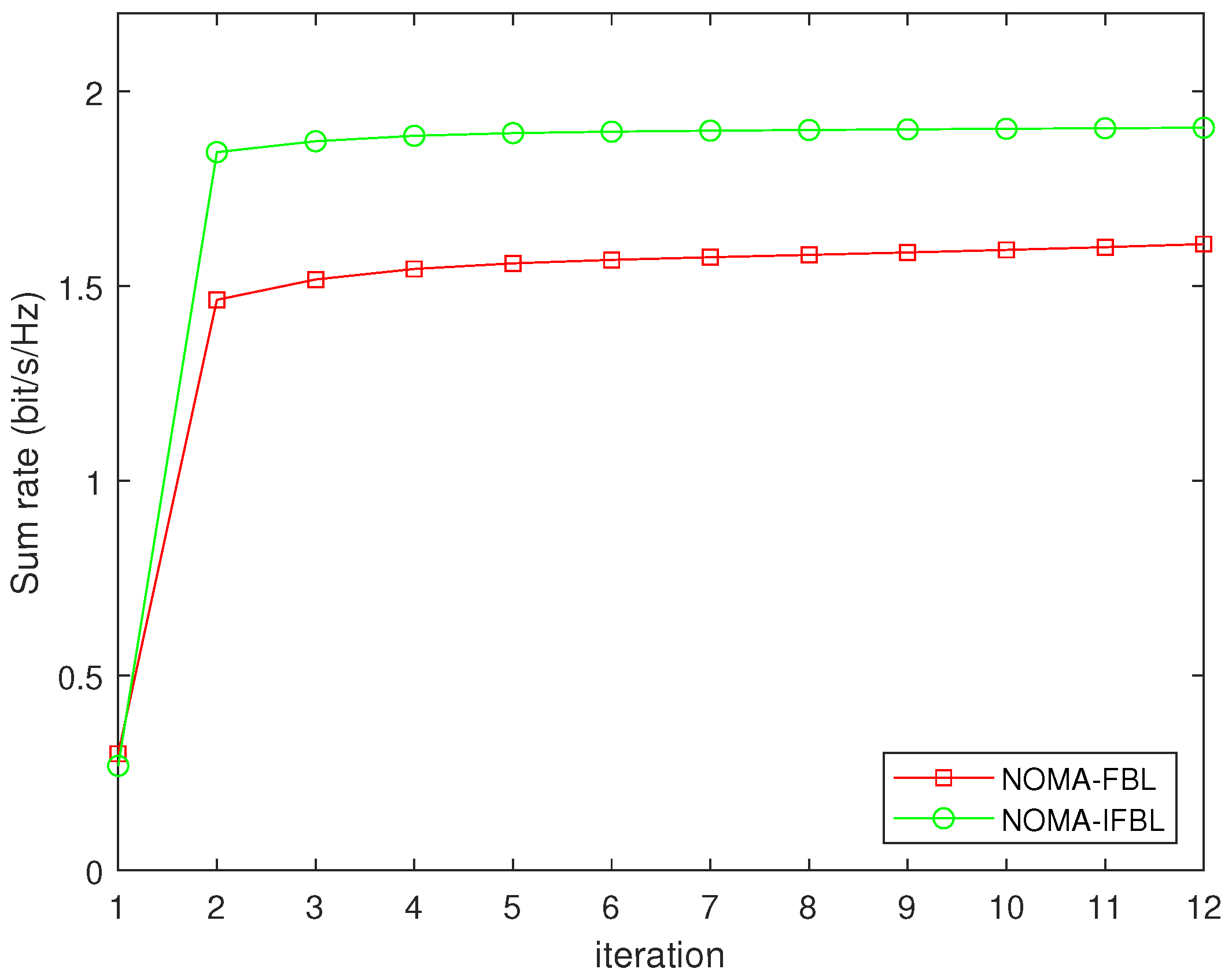
In Figure 2, we verify the convergence of NOMA-FBL and NOMA-IFBL algorithms with maximum transmit power P max = 30 dBm , the number of RIS elements M = 40 . As the number of iterations increases, the sum rate of the system gradually increases. The NOMA-FBL and NOMA-IFBL algorithms fully converge after approximately eight iterations. When the number of iterations is nine, the sum rate of NOMA-FBL accounts for 83.83 % of the NOMA-IFBL algorithm.
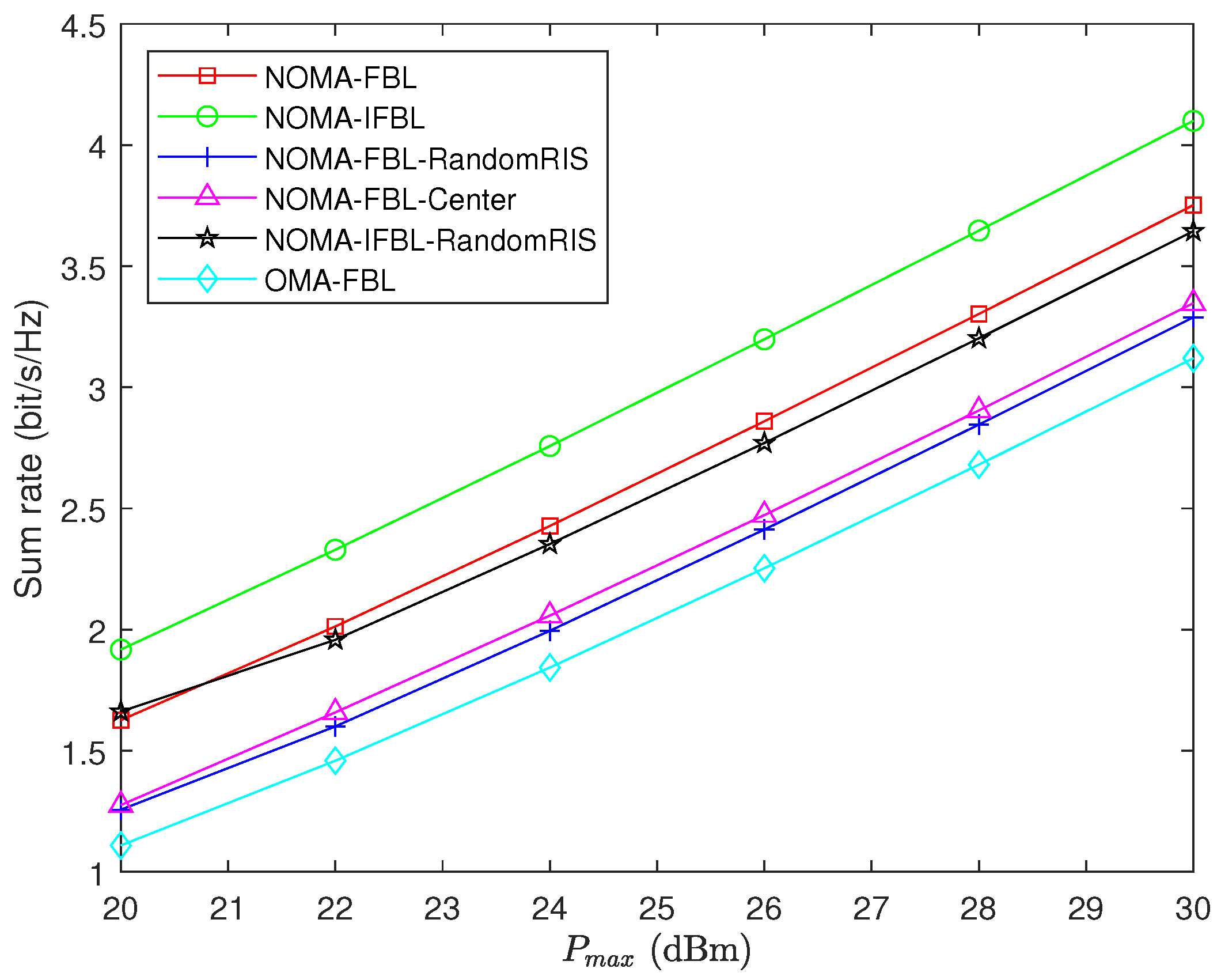
The trend of the sum rate of the system as the maximum transmit power P m a x of the BS is shown in Figure 3. It can be observed that the sum rate of the six schemes increases with the increase of P m a x . This is because the BS allocates more power to each user to achieve a higher sum rate. In addition, the sum rate of the proposed NOMA-FBL algorithm is higher than that of other algorithms except NOMA-IFBL, proving the NOMA-FBL algorithm’s effectiveness. The NOMA-IFBL and NOMA-FBL algorithms for optimizing RIS phase shift are superior to the corresponding NOMA-IFBL-RandomRIS and NOMA-FBL-RandomRIS algorithms, indicating the effectiveness of RIS gain in improving the URLLC systems. For the UAV-RIS-assisted URLLC systems, optimizing the UAV-RIS position can greatly improve the sum rate of the system because adjusting the UAV-RIS position can improve the user’s channel quality and update the NOMA decoding order. Compared to the NOMA-FBL-RandomRIS, NOMA-FBL-Center, and OMA-FBL algorithms, the NOMA-FBL algorithm has improved by 15.66 % , 18.52 % , and 26.91 % , and the sum rate of NOMA-FBL and NOMA-IFBL-RandomRIS algorithms reaches 89.41 % and 86.61 % of the NOMA-IFBL algorithm, respectively, when P max is 26 dBm .
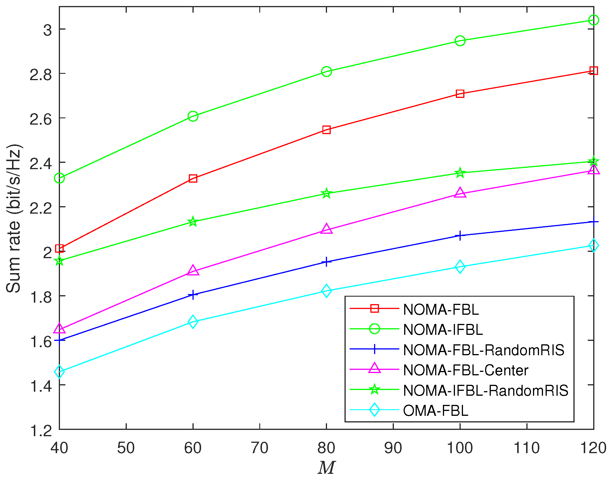
Figure 4 presents the performance of the sum rate of the system versus the number of RIS sub-surfaces M. As M increases, the sum rate of the six algorithms increases. However, the gap between the sum rate of the optimized phase shift algorithm and the random phase shift algorithm is becoming increasingly significant. The reason is that the higher reflection gain can be achieved through the reflection of a quantity of RIS sub-surfaces, and the larger the number of M, the greater the influence on the RIS reflection channel. The proposed NOMA-FBL algorithm improves the sum rate with respect to NOMA-FBL-RandomRIS, NOMA-FBL-Center, and OMA-FBL algorithms by 30.41 % , 21.50 % , and 39.75 % when M equals 80. The sum rate gap between the NOMA-IFBL algorithm and the NOMA-FBL and NOMA-IFBL-RandomRIS algorithms is 0.261 and 0.578 bit/s/Hz, respectively.
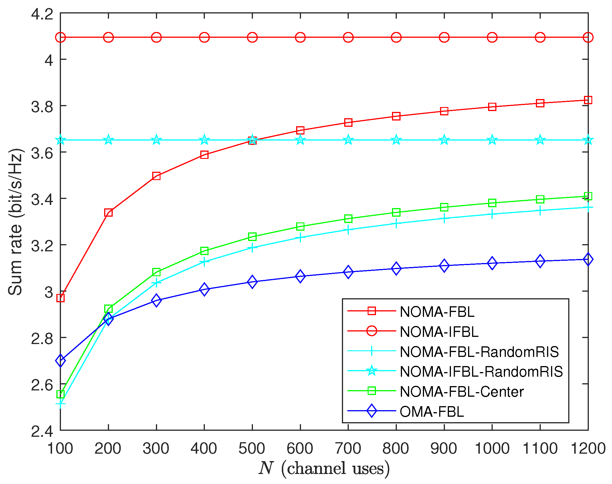
Figure 5 illustrates the relationship between the sum rate of the system and the packet length N under various schemes. The figure demonstrates that the sum rate of all short-packet transmission schemes increases with the increase in packet length and gradually approaches the ideal IFBL transmission scheme. A notable observation is that the trend of sum rate growth slows down as packet length increases. This implies that improving throughput performance at the expense of higher latency is less effective beyond a particular threshold of packet length. In addition, the sum rate of the proposed NOMA-FBL algorithm is higher than that of the OMA-FBL algorithm for any packet length. This indicates that using NOMA technology in short-packet transmission under the same latency conditions can achieve a superior sum rate compared to OMA, and NOMA can effectively reduce latency. When packet length N is 600, the sum rate of the system obtained by the NOMA-FBL-RandomRIS, NOMA-FBL-Center, and OMA-FBL algorithms are about 14.30 % , 12.65 % , and 20.56 % of the NOMA-FBL algorithm.
As shown in Figure 6, when ε k increases from 10 8 to 10 1 , the system sum rate of the FBL scheme increases. Generally speaking, ε k 0.5 . As ε k approaches 0.5, the sum rate difference between the FBL scheme and its corresponding IFBL scheme decreases. This is because the Q 1 ε k is monotonically decreasing in ( 0 , 0.5 ] . Consequently, to boost the sum rate under the FBL scheme, a certain degree of reliability must be compromised. When ε k = 0.1 , the sum rates obtained by the NOMA-FBL and NOMA-FBL-RandomRIS algorithms account for 98.13 % , and 97.33 % of NOMA-IFBL and NOMA-IFBL-RandomRIS respectively.
Figure 7 illustrates the impact of the UAV-RIS position on NOMA URLLC system performance. We set the minimum user rate r t h equals 0 and the UAV-RIS y-axis to 0 m, with a height of 80 m. The NOMA decoding sequence is optimized according to Equation (6), and the remaining variables are optimized according to Algorithm 1. As can be seen from the figure, the sum rate of the three algorithms first increases with the movement of the UAV-RIS and then gradually decreases. When the UAV-RIS is placed between the base station and the users, the system performance is better, indicating a relationship between channel gain and the distance of the UAV from the base station and users. It is noteworthy that the system performance is best for the NOMA-IFBL, NOMA-FBL, and OMA-FBL algorithms when the UAV position is at x = 30 m, x = 32 m, and x = 26 m, respectively.

5. Conclusions

This work proposes a joint optimization algorithm based on BCD to maximize the sum rate of the UAV-RIS-assisted URLLC system based on the NOMA protocol. Specifically, we jointly optimize power allocation, RIS phase shifts, UAV-RIS position, and NOMA decoding order using auxiliary variables, SCA, and penalty functions. Simulation results verify the convergence and superiority of the proposed resource allocation algorithm compared with other benchmark algorithms. Additionally, the simulation results illustrate the performance gap between the proposed communication system and the traditional Shannon capacity to achieve high reliability and low delay. We are currently verifying the theoretical analysis results through Matlab and CVX simulation platforms, and the next step of our work will be to deploy algorithms on the UAV prototype for practical verification of the effectiveness of the proposed algorithm. We will further consider the hardware impairments, noise, and uncertainty of the channel in this work, and design a robust resource allocation algorithm. Moreover, deep reinforcement learning is also commonly used to handle resource allocation problems. We will use deep reinforcement learning as [38] to optimize UAV trajectory, RIS phase shifts, etc. Last but not least, physical layer security is also an issue worthy of attention. Due to the openness of air-to-ground channels, they are easily vulnerable to eavesdropping or attacks. Therefore, we will consider the physical layer security issues under the UAV-RIS-assisted URLLC system.

Author Contributions

Conceptualization, methodology, and software, Q.Z. and B.D.; validation and investigation, Z.W. and K.H.; writing—original draft preparation, Z.W.; and writing—review and editing, L.H. and M.Y.; Funding acquisition, M.Y. All authors have read and agreed to the published version of the manuscript.

Funding

This work was partially supported by the Sichuan Regional Innovation Cooperation Project (2022YFQ0017), Science Foundation for Youths of Natural Science Foundation of Sichuan Provincial (2022NSFSC0936), No.72 General Fund of the China Postdoctoral Science Foundation (2022M720666), and Shandong Provincial Natural Science Foundation (ZR2023QF125).

Data Availability Statement

The data used to support the findings of the current study are available from the corresponding authors upon request.

Conflicts of Interest

The authors declare no conflict of interest.

References

  1. Sutton, G.; Zeng, J.; Liu, R. Enabling Technologies for Ultra-Reliable and Low Latency Communications: From PHY and MAC Layer Perspectives. IEEE Commun. Surv. Tutor. 2019, 21, 2488–2524. [Google Scholar] [CrossRef]
  2. Li, X.; Yao, H.; Wang, J. A near-optimal UAV-aided radio coverage strategy for dense urban areas. IEEE Trans. Veh. Technol. 2019, 38, 9098–9109. [Google Scholar] [CrossRef]
  3. Wang, Z.; Hong, D.; Fan, Z. Resource allocation for UAV-assisted backscatter communication. EURASIP J. Wirel. Commun. 2022, 202, 104. [Google Scholar] [CrossRef]
  4. Ranjha, A.; Javed, M.; Srivastava, G. Intercell Interference Coordination for UAV enabled URLLC with perfect/imperfect CSI using cognitive radio. IEEE Open J. Commun. Soc. 2022, 4, 197–208. [Google Scholar] [CrossRef]
  5. Ranjha, A.; Kaddoum, G.; Dev, K. Facilitating URLLC in UAV-assisted relay systems with multiple-mobile robots for 6G networks: A prospective of agriculture 4.0. IEEE Trans. Ind. Inform. 2022, 18, 4954–4965. [Google Scholar] [CrossRef]
  6. Di, H.; Zhu, X.; Liu, Z. Joint Blocklength and Trajectory Optimizations for URLLC-enabled UAV Relay System. IEEE Commun. Lett. 2024, 28, 118–122. [Google Scholar] [CrossRef]
  7. Elwekeil, M.; Zappone, A.; Buzzi, S. Power control in cell-free massive MIMO networks for UAVs URLLC under the finite blocklength regime. IEEE Trans. Commun. 2023, 71, 1126–1140. [Google Scholar] [CrossRef]
  8. Chen, X.; Zhao, N.; Chang, Z.; Wang, X. UAV-aided secure short-packet data collection and transmission. IEEE Trans. Commun. 2023, 71, 2023. [Google Scholar] [CrossRef]
  9. Wu, Q.; Zhang, S.; Zheng, B.; You, C.; Zhang, R. Intelligent reflecting surface-aided wireless communications: A tutorial. IEEE Trans. Commun. 2021, 69, 3313–3351. [Google Scholar] [CrossRef]
  10. Lin, Z.; Niu, H.; An, K.; Hu, Y.; Li, D.; Wang, J. Pain without gain: Destructive beamforming from a malicious RIS perspective in IoT networks. IEEE IoT J. 2023, 11, 7619–7629. [Google Scholar] [CrossRef]
  11. Deshpande, R.; Katwe, M.; Singh, K.; Dinget, Z. Resource allocation design for spectral-efficient URLLC using RIS-aided FD-NOMA system. IEEE Wirel. Commun. Lett. 2023, 12, 1209–1213. [Google Scholar] [CrossRef]
  12. Hashemi, R.; Ali, S.; Mahmood, N. Deep reinforcement learning for practical phase-shift optimization in RIS-aided MISO URLLC systems. IEEE IoT J. 2022, 10, 8931–8943. [Google Scholar] [CrossRef]
  13. Abughalwa, M.; Tuan, H.; Nguyen, N.; Poor, V.; Hanzo, L. Finite-blocklength RIS-aided transmit beamforming. IEEE Trans. Veh. Technol. 2022, 71, 12374–12379. [Google Scholar] [CrossRef]
  14. Soleymani, M.; Santamaria, I.; Jorswieck, E.; Clerckx, B. Optimization of rate-splitting multiple access in beyond diagonal RIS-assisted URLLC systems. IEEE Trans. Wirel. Commun. 2024, 23, 5063–5078. [Google Scholar] [CrossRef]
  15. Ren, H.; Wang, K.; Pan, C. Intelligent reflecting surface-aided URLLC in a factory automation scenario. IEEE Trans. Commun. 2021, 70, 707–723. [Google Scholar] [CrossRef]
  16. Cao, K.; Tang, Q. Energy Efficiency Maximization for RIS-Assisted MISO Symbiotic Radio Systems Based on Deep Reinforcement Learning. IEEE Commun. Lett. 2024, 28, 88–92. [Google Scholar] [CrossRef]
  17. Wu, M.; Zhu, S.; Li, C.; Zhu, J.; Chen, Y.; Liu, X.; Liu, R. UAV-Mounted RIS-Aided Mobile Edge Computing System: A DDQN-Based Optimization Approach. Drones 2024, 8, 184. [Google Scholar] [CrossRef]
  18. Cheng, T.; Wang, B.; Cao, K.; Dong, R.; Diao, D. IRS-Assisted Secure UAV Communication System for Multiuser With Hardware Impairments. IEEE Syst. J. 2023, 17, 4946–4957. [Google Scholar] [CrossRef]
  19. Bansal, A.; Agrawal, N.; Singh, K.; Li, P.; Mumtaz, S. RIS selection scheme for UAV-based multi-RIS-aided multiuser downlink network with imperfect and outdated CSI. IEEE Trans. Commun. 2023, 71, 4650–4664. [Google Scholar] [CrossRef]
  20. Qin, X.; Song, Z.; Hou, T.; Wang, J.; Sun, X. Joint optimization of resource allocation, phase shift and UAV trajectory for energy-efficient RIS-assisted UAV-enabled MEC systems. IEEE Trans. Green Commun. Netw. 2023, 7, 1778–1792. [Google Scholar] [CrossRef]
  21. Singh, S.; Agrawal, K.; Singh, K.; Li, P.; Ding, Z. NOMA enhanced hybrid RIS-UAV-assisted full-duplex communication system with imperfect SIC and CSI. IEEE Trans. Commun. 2022, 70, 7609–7627. [Google Scholar] [CrossRef]
  22. Lai, H.; Li, D.; Xu, F.; Wang, X.; Ning, J.; Hu, Y.; Duo, B. Optimization of Full-Duplex UAV Secure Communication with the Aid of RIS. Drones 2023, 7, 591. [Google Scholar] [CrossRef]
  23. Pang, X.; Zhao, N.; Tang, J.; Wu, C.; Niyato, D.; Wong, K. IRS-assisted secure UAV transmission via joint trajectory and beamforming design. IEEE Trans. Commun. 2022, 70, 1140–1152. [Google Scholar] [CrossRef]
  24. Zhang, Q.; Zhao, J.; Zhang, R.; Yang, L. Downlink Transmissions of UAV-RIS-Assisted Cell-Free Massive MIMO Systems: Location and Trajectory Optimization. Sensors 2024, 24, 4064. [Google Scholar] [CrossRef]
  25. Ranjha, A.; Kaddoum, G. URLLC facilitated by mobile UAV relay and RIS: A joint design of passive beamforming, blocklength, and UAV positioning. IEEE IoT J. 2021, 8, 4618–4627. [Google Scholar] [CrossRef]
  26. Wei, L.; Wang, K.; Pan, C.; Elkashlan, M. Average Error Probability for UAV-RIS Enabled Short Packet Communications. IEEE Trans. Veh. Technol. 2024, 73, 2912–2917. [Google Scholar] [CrossRef]
  27. Singh, S.; Agrawal, K.; Singh, K.; Clerckx, B.; Li, B. RSMA for hybrid RIS-UAV-aided full-duplex communications with finite blocklength codes under imperfect SIC. IEEE Trans. Wirel. Commun. 2023, 22, 5957–5975. [Google Scholar] [CrossRef]
  28. Zhao, H.; Kong, Z.; Huang, H. Air reconfigurable intelligent surface enhanced multi-user noma system. IEEE IoT J. 2024, 11, 29–39. [Google Scholar]
  29. Al-Hourani, A.; Kandeepan, S.; Lardner, S. Optimal LAP altitude for maximum coverage. IEEE Wirel. Commun. Lett. 2014, 3, 569–572. [Google Scholar] [CrossRef]
  30. Ren, H.; Zhang, Z.; Peng, Z.; Li, L.; Pan, C. Energy minimization in RIS-assisted UAV-enabled wireless power transfer systems. IEEE IoT J. 2023, 10, 5794–5809. [Google Scholar] [CrossRef]
  31. Mu, X.; Liu, Y.; Guo, L.; Lin, J.; Poor, V. Intelligent reflecting surface enhanced multi-UAV NOMA networks. IEEE J. Sel. Areas Commun. 2021, 39, 3051–3066. [Google Scholar] [CrossRef]
  32. Polyanskiy, Y.; Poor, V.; Verdú, S. Channel coding rate in the finite blocklength regime. IEEE Trans. Inf. Theory 2010, 56, 2307–2359. [Google Scholar] [CrossRef]
  33. Boyd, S.P.; Vandenberghe, L. Convex Optimization; Cambridge University Press: Cambridge, UK, 2004. [Google Scholar]
  34. Wu, Q.; Zhang, R. Intelligent reflecting surface enhanced wireless network via joint active and passive beamforming. IEEE Trans. Wirel. Commun. 2019, 18, 5394–5409. [Google Scholar] [CrossRef]
  35. Luo, Z.; Ma, K.; So, A.; So, A.M.C. Semidefinite relaxation of quadratic optimization problems. IEEE Signal Process. Mag. 2010, 27, 20–34. [Google Scholar] [CrossRef]
  36. Xu, D.; Zhao, H.; Zhu, H. Resource allocation for secure short packet communications in wireless powered IoT networks. IEEE Trans. Veh. Technol. 2023, 72, 11000–11005. [Google Scholar] [CrossRef]
  37. Amjad, M.; Musavian, L.; Aissa, S. NOMA versus OMA in finite blocklength regime: Link-layer rate performance. IEEE Trans. Veh. Technol. 2020, 69, 16253–16257. [Google Scholar] [CrossRef]
  38. Adam, A.; Wang, Z.; Wan, X.; Xu, Y.; Duo, B. Energy-Efficient Power Allocation in Downlink Multi-Cell Multi-Carrier NOMA: Special Deep Neural Network Framework. IEEE Trans. Cogn. Commun. Netw. 2022, 8, 1770–1783. [Google Scholar] [CrossRef]
Figure 1. UAV-RIS-assisted URLLC System.
Drones 08 00301 g001
Figure 2. Convergence of NOMA-FBL and NOMA-IFBL algorithms for maximizing the sum rate of system.
Drones 08 00301 g002
Figure 3. Sum rate versus maximum transmit power P m a x for M = 40 , N = 1000 , ε k = 10 5 .
Drones 08 00301 g003
Figure 4. Sum rate versus number of RIS sub-surfaces M for P m a x = 30 dBm , N = 1000 , ε k = 10 5 .
Drones 08 00301 g004
Figure 5. Sum rate versus packet length N for P m a x = 30 dBm , M = 40 , ε k = 10 5 .
Drones 08 00301 g005
Figure 6. Sum rate versus decoding error probability ε k for P m a x = 30 dBm , M = 40 , N = 1000 .
Drones 08 00301 g006
Figure 7. Sum rate versus x-coordinate of UAV-RIS for P m a x = 30 dBm , M = 40 , N = 1000 , ε k = 10 5 .
Drones 08 00301 g007
Table 1. Simulation Parameters.
Maximum transmit power P m a x 30 dBm
Channel power at d = 1   m 30 dB
LoS probability threshold κ L o S = 0.9
Noise power σ 2 = 100 dBm
Element spacing of RIS λ 2
Number of IRS reflecting elements M40
Constants related to the environment l 1 = 11.95 , l 1 = 0.14
Packet error rate ε k = 10 5
Minimum user rate r t h 0.1
packet length N1000
Disclaimer/Publisher’s Note: The statements, opinions and data contained in all publications are solely those of the individual author(s) and contributor(s) and not of MDPI and/or the editor(s). MDPI and/or the editor(s) disclaim responsibility for any injury to people or property resulting from any ideas, methods, instructions or products referred to in the content.