Abstract
In this paper, an autonomous landing guidance strategy is proposed for quad-UAVs, including landing marker detection, altitude estimation, and adaptive landing commands generation. A double-layered nested marker is designed to ensure that the marker can be captured both in high and low altitudes. A deep learning-based marker detection method is designed where the intersection of union is replaced by the normalized Wasserstein distance in the computation of non-maximum suppression to improve the detection accuracy. The UAV altitude measured by inertial measurement unit is fused with vision-based altitude estimation data to improve the accuracy during the landing process. An image-based visual servoing method is designed to guide the UAV approach to the landing marker. Both simulation and flight experiments are conducted to verify the proposed strategy.
1. Introduction
Unmanned aerial vehicles (UAVs) are widely used in various fields, due to their small size, flexible operation, and stable flight [1]. One of the most important tasks for a UAV is autonomous landing without human intervention. This is crucial for the real application of UAVs in different fields, such as shipboard landing [2], UAV carrier landing [3], package delivery [4], returning of spacecraft [5], etc. Recently, vision-aided guidance, navigation, and control technology for UAV attracts much attention with the help of computer vision technology [6,7,8]. It shows great potential in the capability of low cost, anti-interference, and autonomous operation for guidance and navigation.
In vision-based landing guidance, the landing marker detection and landing guidance strategy are key technologies. Landing markers serve the purpose of providing visual guidance and positioning information during the landing of a UAV. The commonly used markers include: (1) well-shaped markers such as “H”, “T”, circles, rectangles, etc. [9], (2) QR code-based landing markers such as QR, ArUco, AprilTag, etc. [10], and (3) composite landing markers which are combined by multiple geometric shapes or constructed by nested QR codes [11]. The composite landing markers can adapt to changes in the UAV’s field view and is currently one of the most used landing markers. In [12], a multi-level marker that facilitates the detection of landing markers by UAVs at high altitudes is proposed. In [13], a marker consisting of a circle and two vertical line segments inside is designed to estimate the altitude of the UAV. In [14], a nested QR code is designed for the precise landing of the UAV. An optimal landing marker design should exhibit a harmonious balance between the speed of recognition and the range of visibility.
The guidance strategy also plays critical role in the UAV landing process. Regarding the autonomous landing guidance strategy, many studies have been conducted. In [15], image-based visual servoing and feature shape compensation is proposed for the UAV landing on ships. In [16], a new method for estimating rotation and translation between two camera views by at least five matching corners is proposed. In [17], a vision tracking and landing algorithm on a moving platform is proposed for a multi-rotor UAV. In [18], the visual landing method for low-cost quad-UAV on unknown mobile platforms is designed. In [19], a robust controller is proposed for two separate stages during the UAV landing. In [20], a point clustering relative position estimation algorithm is proposed. In [21], a carrier landing system with fixed-time controller is presented. In [22], a model predictive controller is developed for non-horizontal landing. In [23], a trajectory planning method is proposed for UAVs with low maneuverability to land on charging platforms. In [24], an elastic visibility aware planning and flexible adjustment method is designed for UAV landing on sloping platforms. However, the above research shows certain constraints. For example, the solution of landing on a ship is suitable for large UAVs while it is hard to apply to the small UAVs with limited computation resources. In addition, most of existing low-cost landing solutions for small UAVs have the problem of inaccurate visual estimation.
In this paper, an autonomous landing guidance strategy is designed for a small quad-UAV based on nested landing marker and fused altitude. A newly designed multiscale landing marker is captured by the onboard camera and processed by the modified YOLOv4. The lateral and vertical positions are estimated based on the vision information and fused altitude. Then, the landing commands are generated by the image-based visual servoing method. The main contributions of this study include the following:
(1) A landing marker detection method is designed to detect the double-layered ArUco marker which is obtained by combining two special ArUco codes in a certain pattern. In the detection, the normalized Wasserstein distance (NWD) is used to substitute for the intersection of union (IoU) to calculate the similarity between bounding boxes of adjacent small targets which is predicted by YOLOv4. By this means, the detection accuracy of the landing marker is improved in complex flight environments such as multiple small obstacles occurring at the same time or the marker being partially covered by obstacles.
(2) The altitude is a key state during the whole landing process. The relative altitude between the UAV and the marker calculated by the visual Perspective-n-Point (PnP) method often has errors. Hence, an altitude correction method is proposed by fusing the image-based altitude and inertial measurement unit-based altitude. By such means, the estimation accuracy of the altitude is improved, leading to a more precise landing result consequently.
(3) A re-guidance strategy together with the image-based visual servoing method is designed considering the moving of the marker or the interruption during the landing. By the landing marker recapture method, an adaptive landing guidance is achieved for the quad-UAV. The performance of the proposed strategy is verified by multiple simulations and flight experiments in different scenarios.
The rest of this paper is outlined as follows. Section 2 describes the framework of the proposed landing guidance strategy. Section 3 presents the marker design and detection algorithm. In Section 4, the position estimation and adjustment are described. The overall realization process of the proposed landing strategy is presented in Section 5. Section 6 analyzes the test results. Section 7 concludes the paper.
2. The Framework of Proposed Landing Guidance
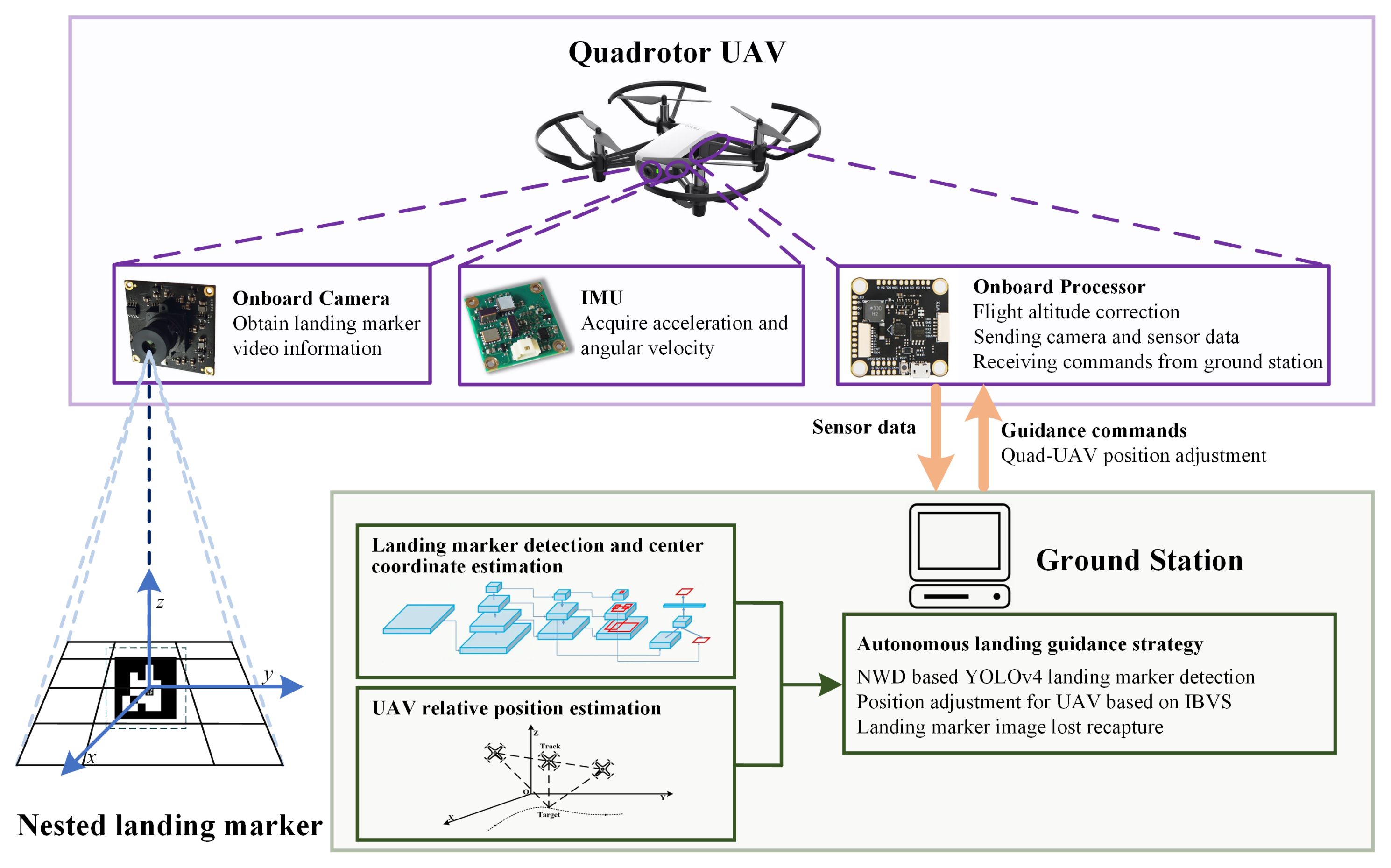
The proposed UAV landing guidance system is shown in Figure 1 consisting of a quad-UAV, the landing marker, and the ground station. The quad-UAV is equipped with a camera, inertial measurement unit (IMU), and onboard processor. The monocular camera is used to capture the landing marker video information. The IMU is used to obtain the acceleration and angular velocity of a UAV. The onboard processor communicates with the ground station by WiFi. In the onboard processor, the data from the onboard sensors are processed and then sent to the ground station.
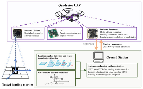
Figure 1.
Framework of the vision-based guidance system for a quad-UAV.
The landing marker is attached to a fixed or moving target. A nested marker is designed aiming to accommodate varying height perspectives of the UAV. By integrating multiple scales of the ArUco into the marker, the visibility and positional accuracy are enhanced under different viewing angles.
On the ground station, the visual information received from the UAV is detected by the modified YOLOv4 algorithm. The landing marker is detected, and its center coordinate is estimated. Based on the visual image and other sensor information, the PnP method is used to estimate the relative position of the UAV and landing marker. Afterwards, the position information is sent to the landing guidance module.
Furthermore, an autonomous landing guidance strategy is designed to generate guidance commands for the UAV. The commands are then transmitted to the UAV via WiFi to guide the UAV towards the marker during its approach.
3. Landing Marker Design and Detection
3.1. Nested Landing Marker Design
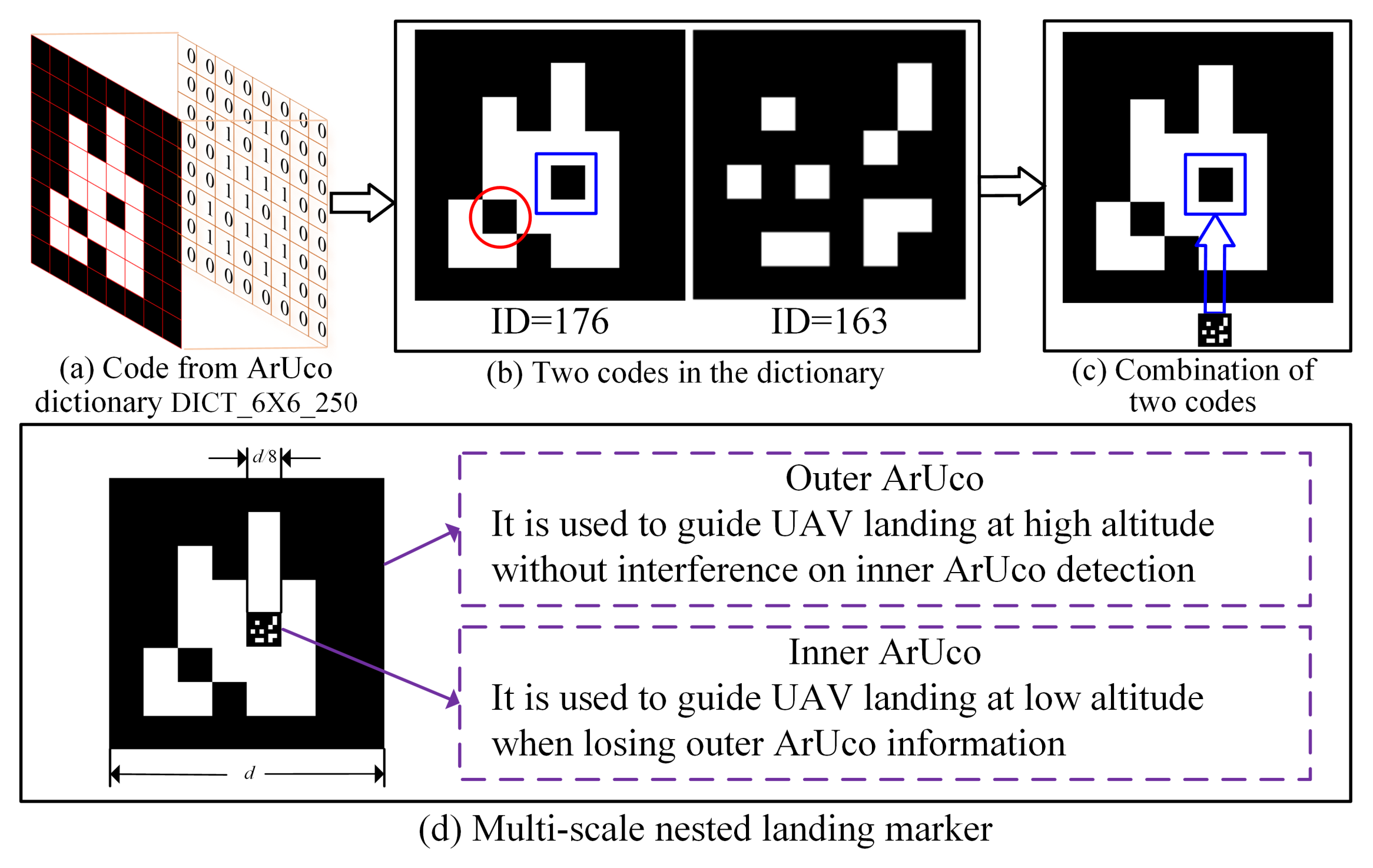
The landing marker is used for locating the relative position between the UAV and landing site, which is supposed to be easy to distinguish and adaptive to multiple views of UAV. The ArUco [25], which contains a set of binary square reference markers, is used in this paper. But traditional ArUco cannot guarantee accurate detection under different altitudes. Hence, a nested landing marker is designed as shown in Figure 2.
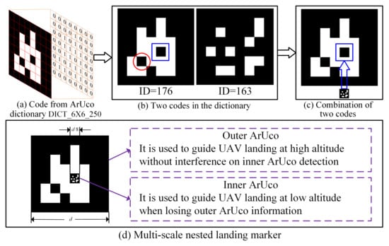
Figure 2.
The design principle of multi-scale marker.
The ArUco dictionary named DICT_6X6_250 is selected, where the code consists of an outer black border and an inner area that encodes 6 × 6 binary patterns, as depicted in Figure 2a. Two codes named ID176 and ID163 in the dictionary are used. It can be observed from Figure 2b that, in the center of code ID176, there is a black block wrapped by a white area, as labeled by the blue box. The boundary of this block can be clearly observed and easily distinguished. This feature inspires us that the black block can be replaced by another ArUco for close-ground guidance. Hence, the code ID163 is inserted into ID176 as depicted in Figure 2c. The advantage of ID163 lies in that it is mostly made up of black blocks and using it as an inner marker will not affect high-altitude identification. Finally, the combined multi-scale nested landing marker is given in Figure 2d, where the outer ArUco is used to guide the UAV at high altitudes, and the inner one is for low altitudes when the outer one cannot be fully observed.
Note that the selection principle of the outer-layer ArUco is to make sure that one inner black block is fully wrapped by a white area, as shown by the blue rectangle box in Figure 2b. The selection principle of inner ArUco is that the small white blocks in ArUco code spread out as much as possible, which has much information and is easy for marker detection in the process of low-altitude guidance. As depicted in Figure 2c, the blue rectangle box is then replaced by the inner ArUco code. It is worth noting that the black block labeled by the red circle in Figure 2b is not an appropriate choice for locating the inner ArUco code. The reason is that the neighbored black part near the red circle has the same feature (i.e., the edge between the white and black) as the outer black part of the inner ArUco code (i.e., ID 163), which will affect the detection precision in the low-altitude guidance process.
Remark 1.
During the landing process, the view field of the onboard camera will change due to the continuous variations in UAV altitude. When the UAV approaches the landing marker, the view field will decrease, making it hard to capture the complete marker. The relative position thus cannot be accurately estimated, which results in failure of the landing task. In this paper, a double-layer marker is designed. The outer ArUco is used to guide the UAV to approach the marker when the UAV is flying at high altitude. As the altitude continues to decrease, the proportion of outer ArUco pixels in the onboard camera’s view gradually decreases, while the inner ArUco image gradually becomes clear. Hence, the inner ArUco is switched to guide the UAV to the marker.
3.2. Landing Marker Detection Algorithm
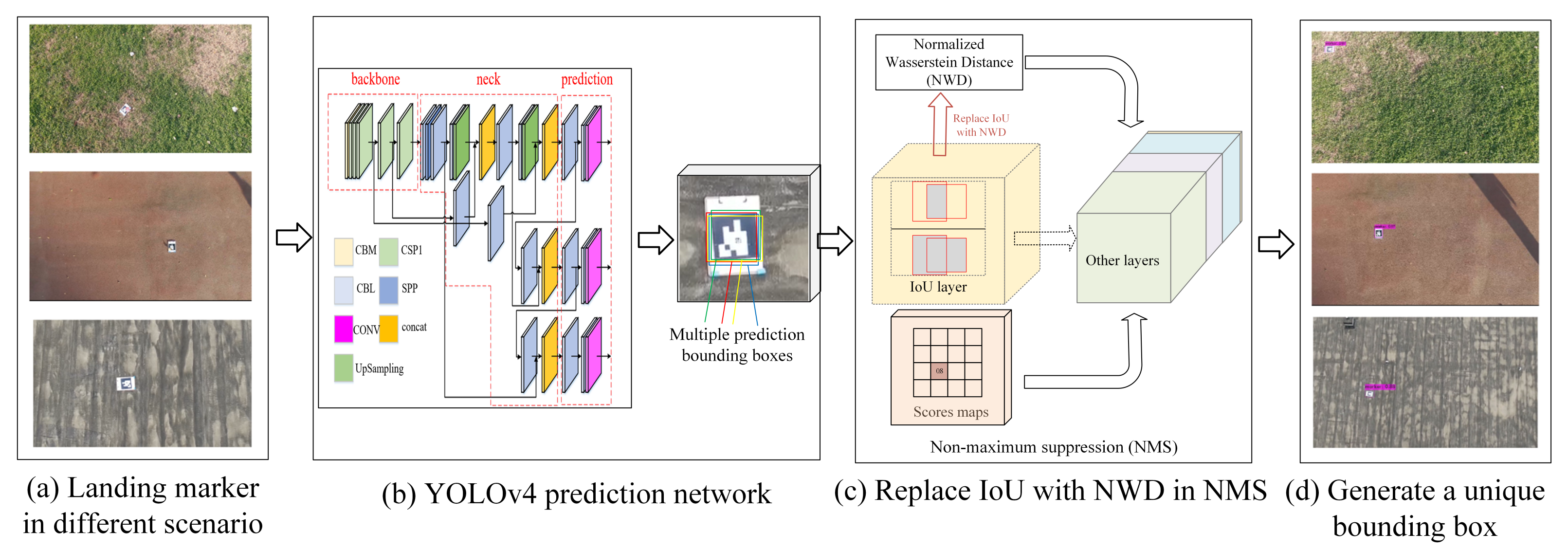
During the landing process, the marker should be detected in a timely manner for relative position computation. In this section, a modified detection algorithm is designed as seen in Figure 3. The image with landing markers inside is captured by the onboard camera. The You Only Look Once (YOLO)-v4 neural network is used for marker detection in Figure 3b. The prediction layer outputs multiple prediction bounding boxes. Non-maximum suppression (NMS) is then used to select the unique bounding box. Traditionally, the IoU is used in NMS. However, the IoU-based NMS is sensitive to the position deviation of small objects and is not suitable for UAV landing tasks. In this paper, normalized Wasserstein distance [26] is used to replace the IoU, as illustrated in Figure 3c, which can overcome the problem of scale sensitivity. The detailed principle of the YOLOv4 network can be referred to [27]. The modification with NWD is presented below.
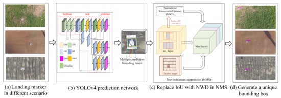
Figure 3.
The proposed NWD-YOLOv4 detection algorithm.
3.2.1. Build Bounding Box Selection by NMS
As mentioned above, multiple prediction bounding boxes are obtained by the YOLOv4, from which the unique box needs to be selected using NMS. In this process, the similarity between different bounding boxes should be calculated. In this paper, the NWD is used for similarity calculation as follows.
Firstly, the bounding box model is formulated based on the distribution of pixel importance in the box. In particular, for a bounding box , where , a, and b represent the center coordinates, width, and height, respectively. The inscribed ellipse of the bounding box is calculated by
where represents the central coordinate of the ellipse, represent half axis length along the x and y axis. The probability density function of a two-dimensional (2D) Gaussian distribution is obtained by
where G represents Gaussian distribution coordinates , represents the mean vector of N, and represents the covariance matrix of G. If is satisfied, the ellipse in (1) would be a density profile of a 2D Gaussian distribution.
Then, the similarity between different bounding boxes can be converted to the distribution distance between two Gaussian distributions. For bounding boxes and , the Gaussian Wasserstein distance between them is defined by
where is the Frobenius norm. For bounding boxes and , the Gaussian distribution model can be obtained by substituting (3) into (4):
Finally, by normalizing S exponentially, the NWD is obtained by , where C is a constant.
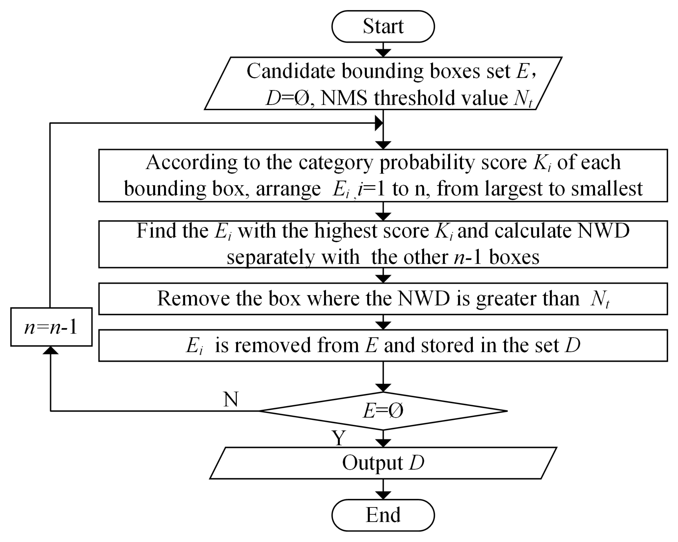
3.2.2. The NMS Algorithm Based on NWD
By the above NWD calculation, the traditional IoU is replaced in the NMS as depicted in Figure 3c. This enables the NMS to measure similarity between non-overlapping or mutually contained bounding boxes. The flowchart of NWD-based NMS to select unique one from multiple bounding boxes is shown in Figure 4.
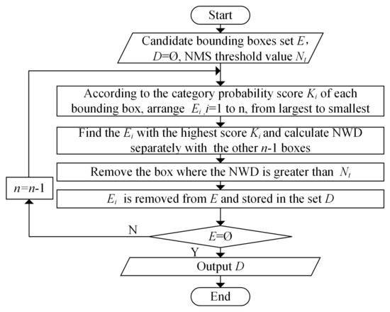
Figure 4.
The flowchart of NMS algorithm based on NWD.
Step 1. Define n boxes in all predicted bounding boxes from YOLOv4 as . The corresponding category probability score is recorded by . Set as the threshold of NMS, and the initial set of the unique box is ;
Step 2. According to the category probability score of each bounding box, the boxes are sorted from largest to smallest. The descending order is denoted as ;
Step 3. In E, starting from the bounding box with the highest category probability score M, and calculating the NWD value of the bounding box and each remaining bounding box in E. If the NWD is greater than the threshold, is removed. At the end of traversal, the bounding box with the largest category probability score is removed from E and stored in set D;
Step 4. For the remaining bounding boxes in E, starting from the sub-largest category probability score, it is necessary to repeatedly perform the iterative operation in Step 3 until all the bounding boxes in E are filtered.
Remark 2.
Traditional ArUco detection method [25] requires that all four feature corners of ArUco are clear and detectable. It will fail to detect the marker if the ArUco feature points are partially occluded. However, in the real application, the flight and landing environments are with uncertainties. In addition, for the detection of small landing markers during high-altitude flight of UAVs, using conventional NMS will reduce detection accuracy. To solve these two issues, an NWD-based NMS combined with YOLOv4 deep learning algorithm is proposed in this section, where NWD is used to calculate the similarity between two adjacent bounding boxes, replacing the traditional IoU metric. By this means, detection accuracy can be improved in the case of marker obstruction and small target in high flight altitude during the UAV landing process.
4. Landing Guidance Command Generation
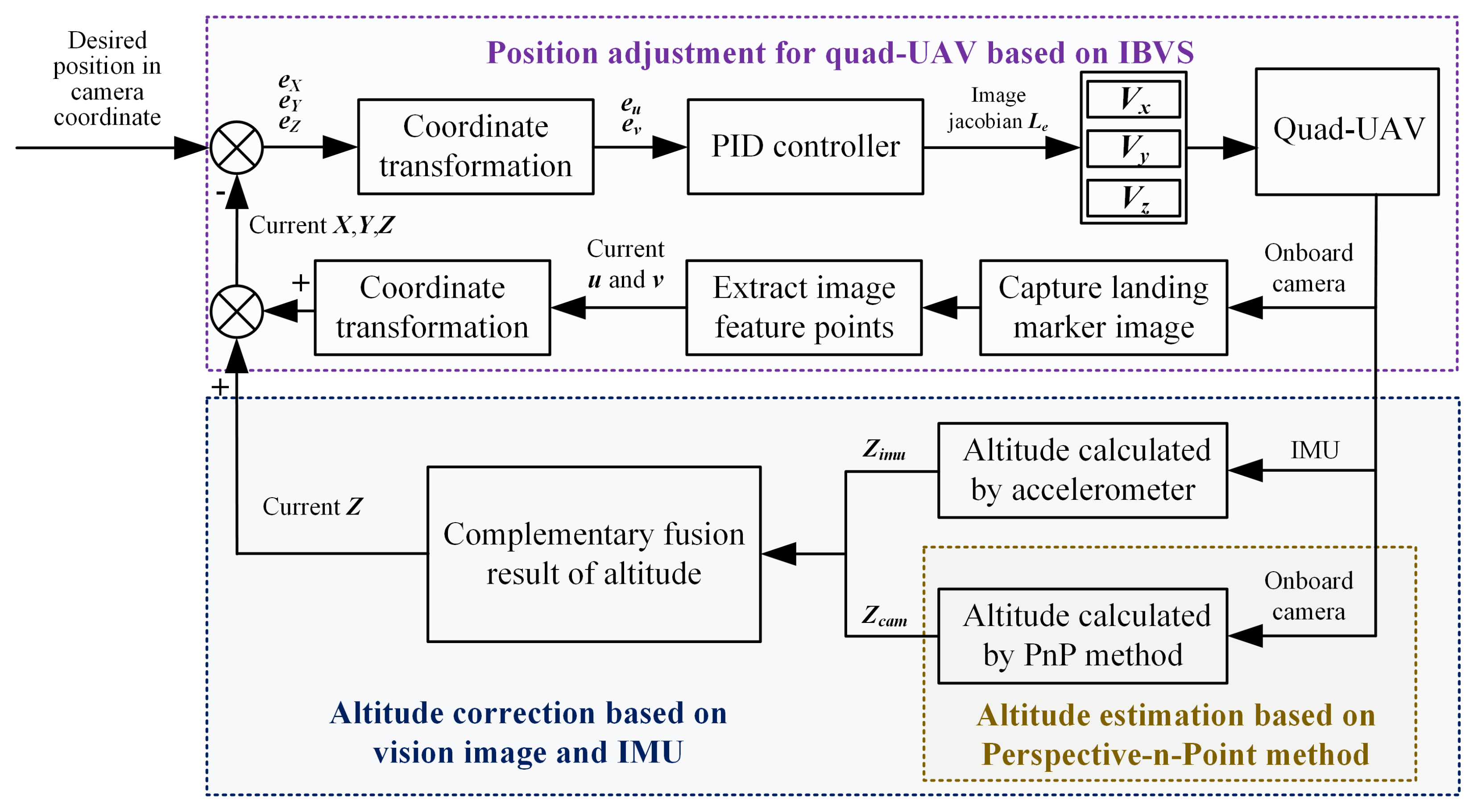
Based on the visual image obtained from onboard camera in the above section, the position estimation and adjustment methods are designed to generate the guidance commands in this section. The principle includes altitude correction and position adjustment in Figure 5.
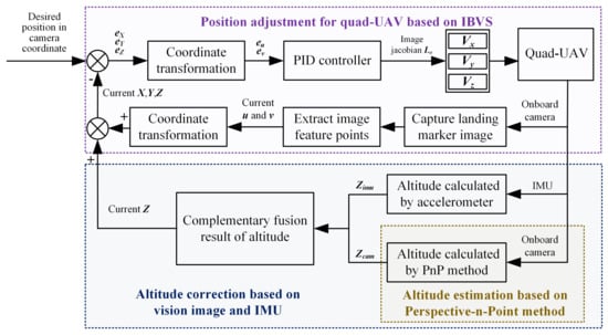
Figure 5.
The principle of position estimation and adjustment of UAV.
In the altitude correction module, the relative lateral position and altitude of quad-UAV are firstly estimated with the PnP method. But the altitude estimated from the image has errors. Hence, the altitude is corrected by fusing the IMU data and image estimation data. In the position adjustment module, the image-based visual servoing (IBVS) algorithm is designed to adjust the position deviation between the UAV and landing marker.
4.1. Altitude Correction for the UAV
4.1.1. UAV Localization Based on Perspective-n-Point
The PnP-based localization method mainly estimates the relative lateral position and altitude of the UAV by solving the coordinate system transformation relationship between 3D space and 2D plane. In this paper, the UAV body coordinate system is assumed to be consistent with the onboard camera coordinate system, since the UAV is a small rigid body and the camera is attached to the UAV with a fixed position.
Given the camera intrinsic parameters as , and are focal lengths in the direction, representing the distance from the optical center of the camera to the image plane. and are the coordinates of the center point of the image, that is, the position on the image plane corresponding to the intersection of the camera optical axis. The position of target point in the earth-fixed coordinate system is , the coordinate in camera coordinate system is , and the coordinate in pixel coordinate system is , and the relationship between pixel and earth-fixed position can be obtained as follows:
with rotation matrix and translation matrix . u and v can then be calculated by
where represent the offset of the origin of the image coordinate system on the pixel coordinate system.
During UAV flight, the camera intrinsic parameter matrix and the size of the actual landing marker are calculated. The marker size in the pixel coordinate system is obtained by the onboard camera. By calling the PnP function and the Rodrigues rotation formula [28], R and T can be calculated. According to the above description, by continuously reading the coordinates of the landing marker in the pixel coordinate system and calculating R and T, the and of the UAV relative to the landing marker can be updated in real time.
4.1.2. Altitude Correction Based on Vision Image and IMU
In horizontal direction, the above PnP-based method can achieve good accuracy, while the estimated altitude has large errors. Therefore, additional IMU information is used to correct UAV altitude.
In IMU, acceleration information can be obtained by the built-in accelerometer. After filtering and quadratic integration of acceleration, altitude information can be obtained. However, the accelerometer itself has errors. As the UAV flight time increases, the degree of error accumulation increases. In addition, the measurement principle of accelerometers makes them sensitive to high-frequency signals and susceptible to high-frequency interference in vibration environments.
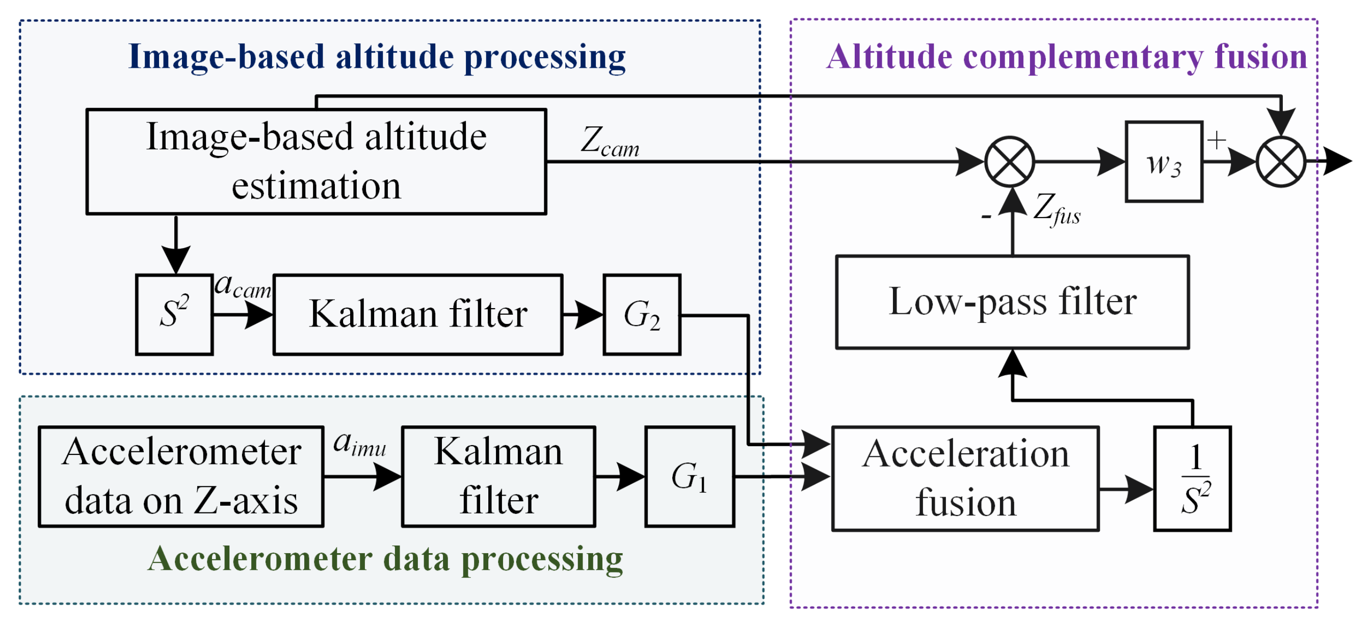
Considering the above factors, the data obtained through IMU and image are fused. After filtering, the problem of data lag caused by image processing is solved, and UAV altitude can be obtained accurately. The diagram of altitude estimation is given in Figure 6.
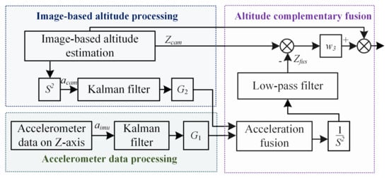
Figure 6.
The schematic diagram of altitude estimation.
Step 1. Due to the fact that the acceleration data measured by the accelerometer are susceptible to external noise, the Kalman filter is first used to process the acceleration data. The obtained acceleration is recorded as .
Step 2. Perform quadratic differentiation on the altitude data obtained from image information processing, denoted as . Due to the fact that these data are prone to interference and generate a large amount of noise in actual operation, they are filtered and processed. The obtained acceleration data are denoted as .
Step 3. Design a complementary filter composed of low-pass filter and high-pass filter to fuse the accelerometer measurement data with the differentially processed image data to obtain , where is the time constant.
Step 4. The acceleration data after fusion are integrated twice to obtain the altitude data , which are then processed again through the low-pass filter to filter out high-frequency noisy data.
Step 5. The UAV altitude is corrected by compensating , obtaining .
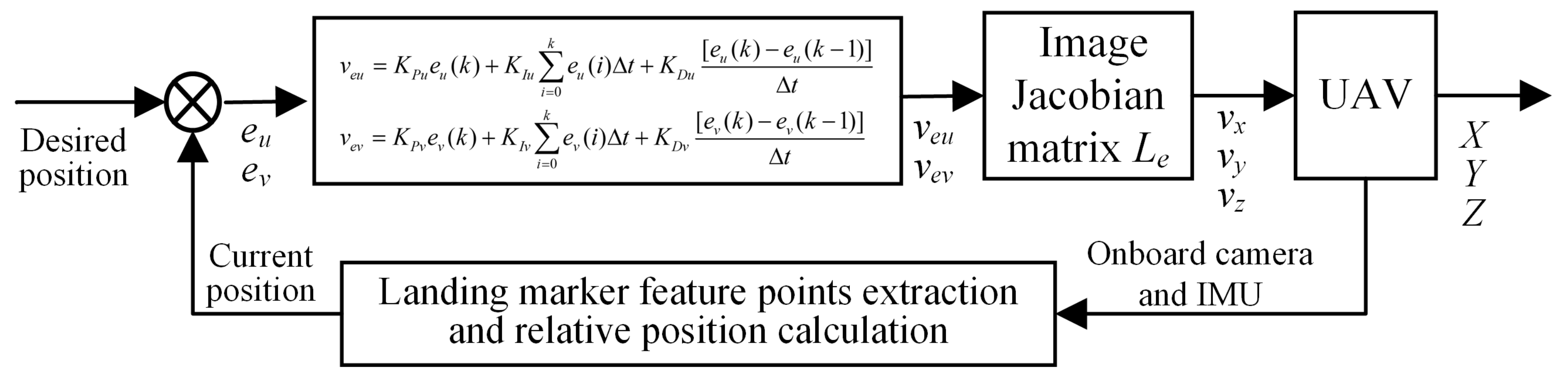
4.2. Position Adjustment for the UAV
This section mainly introduces the UAV guidance system based on IBVS in Figure 7. Using the desired position in pixel coordinate as input signal and the current relative position as feedback signal, the position deviation is obtained. The guidance command is obtained by inputting the deviation into PID law. Then, by multiplying the command with image Jacobian matrix , the speed required by the UAV is obtained. By changing the UAV speed, the position changes and gradually approaches the target point. A closed-loop guidance law is thus formed through visual feedback.
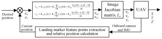
Figure 7.
The UAV guidance commands generation based on IBVS.
The deviation variables are input into the PID controller to obtain the change rate of feature points on the pixel plane, as shown in (8):
where, represent position deviations in u and v axis, represent change speeds of feature points in the u and v axis. , and represent proportional, integral, and differential coefficients. represents sampling interval. Assuming that the center point of the marker has coordinates in the camera coordinate system and in the image coordinate system. The image Jacobian matrix [29] is
Based on the change speed of the feature points and the Jacobian matrix, the UAV speed is calculated by
where represent linear flight velocities, represent angular velocities, and is constant.
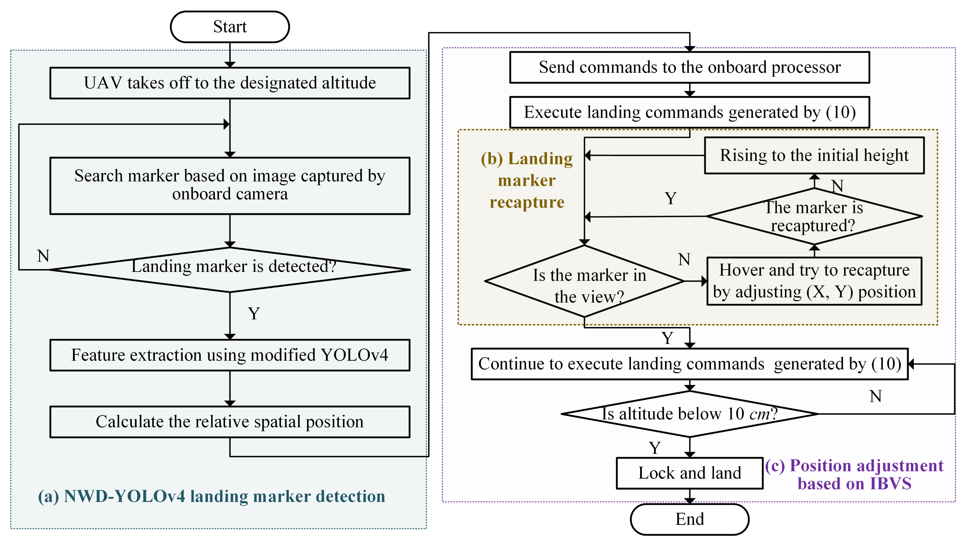
5. Landing Guidance Realization
The process of the proposed vision-based landing guidance system for quad-UAV is summarized in Figure 8. Firstly, the UAV reaches the landing area and the visual landing stage is initiated. The marker is captured by the onboard camera, and detected by the NWD-YOLOv4 network as shown in Figure 8a. The pixel coordinates of the center point of the landing marker are output, and the coordinate system is converted using the PnP algorithm. The coordinates of the UAV in the camera coordinate system are obtained. The vision-based altitude and IMU-based altitude are fused to obtain the corrected altitude data.
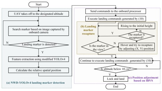
Figure 8.
Flowchart of the proposed UAV landing guidance.
The speed commands are then calculated by (10) using deviation between the current position of the landing marker and the target position in the image. The UAV is guided to continuously approach the landing marker.
In response to the issue of loss of landing marker images during the landing of the UAV, a re-guidance strategy is proposed for capturing the lost landing marker, as shown in Figure 8b. When the target image is lost, the UAV hovers and tries to obtain the image again. If the image still cannot be captured, it will rise to the initial height in place, expand the field of view of the onboard camera, and capture the image again. When the UAV executes a landing command and the flight altitude is 10 cm above the ground, the UAV locks down and lands autonomously and safely on the landing marker.
6. Simulation and Experiment
In this section, simulations and experiments are conducted to verify the performance of the proposed strategy. The marker detection algorithm is firstly demonstrated by using multiple images of the marker captured from different angles of view. Then, the altitude correction method proposed is analyzed. After that, the simulation tests under AMOVLab platform are conducted. At last, flight experiments are conducted using DJI-Tello UAV. The code and video of the proposed algorithm can be viewed in [30,31].
6.1. Landing Marker Detection Results Analysis
A dataset is constructed by collecting different images of the marker at different UAV view fields. The flight heights are 5 m, 10 m, and 15 m. Different scenarios are considered including similar backgrounds, strong lighting, similar small targets, and natural grassland. The objects being photographed include the landing marker, book, and person, where the landing marker is the main target, while the book and person are interferences. The dataset is then annotated on Labeling software. Three types of objects are labeled as ArUco, book, and person, respectively. The data format of the labels is PascalVoc, resulting in 5818 training samples and 443 test samples for algorithm validation. After the annotation is completed, the file is saved in XML format. The prepared dataset is used for training the NWD-YOLOv4 model and to verify the detection performance of the model.
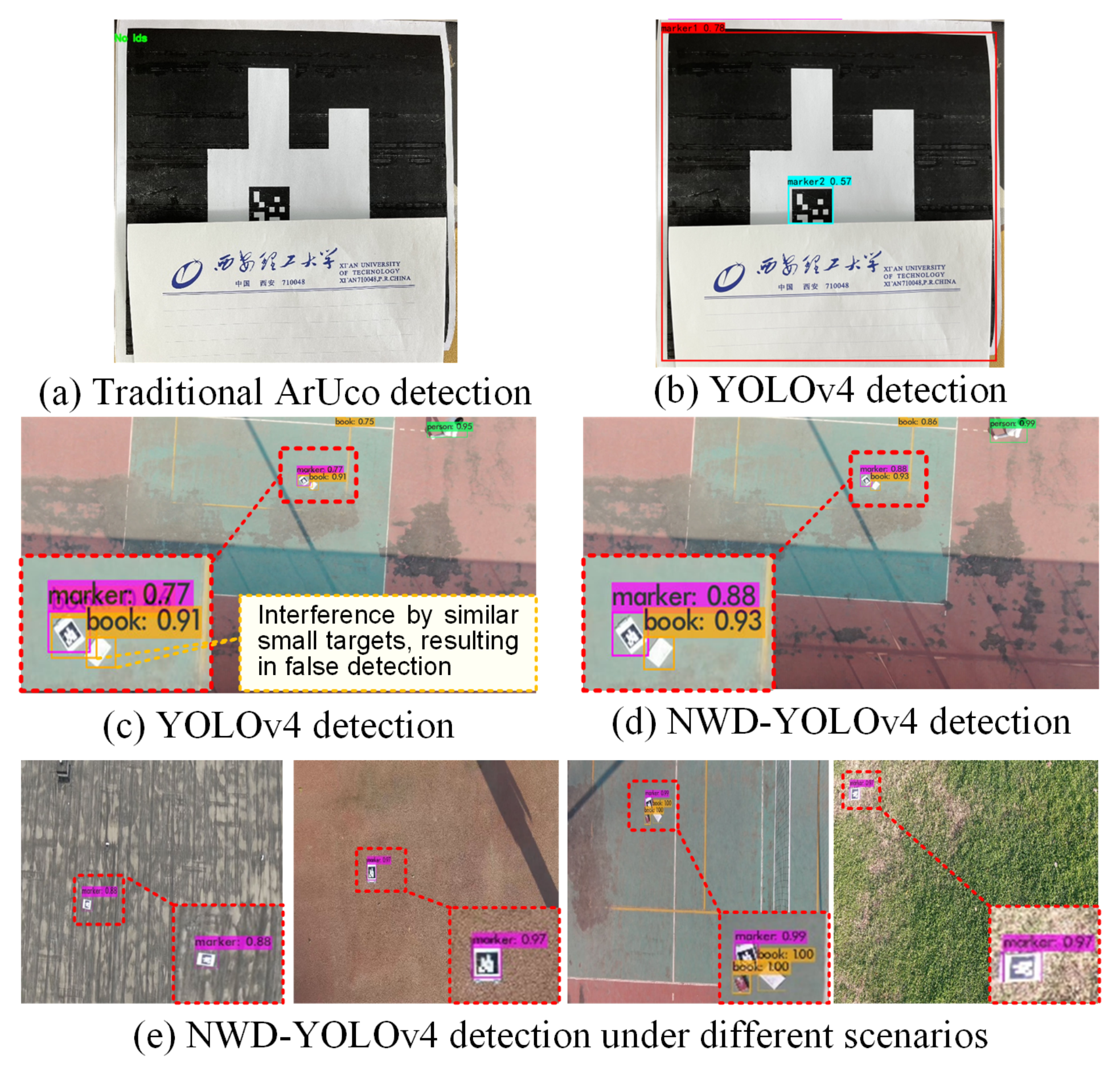
Figure 9 presents the comparison results obtained by the traditional ArUco detection algorithm, YOLOv4 algorithm, and NWD-YOLOv4 algorithm. In Figure 9a,b, the marker is partially obscured. The results illustrate that the traditional ArUco extraction algorithm [32] fails to detect it as shown in Figure 9a even under an ideal environment and the marker is large enough, whereas the YOLOv4-based algorithm can detect the obscured ArUco with a high accuracy of 87.22%, as shown in Figure 9b. In Figure 9c,d, the image is captured under the same field of view of the UAV. Additional small targets including a book and a person are joined, which cause interferences near the landing marker. The detection result of the marker by the YOLOv4 algorithm is 76.85%, as depicted in Figure 9c. When multiple adjacent small targets appear within the field of view of the UAV, it is easy to cause false detection. This is because the IoU used in traditional YOLOv4 is very sensitive to small target scales, and it is difficult to measure the similarity between two boxes when they intersect little. However, by employing the improved NWD-YOLOv4 detection algorithm, it becomes capable of distinguishing multiple small targets with higher detection accuracy reaching 88.36%, as depicted in Figure 9d. In Figure 9e, these images are captured under different fields of view of the UAV. These scenarios contain similar backgrounds, strong lighting, similar small targets, and natural grassland. Using the NWD-YOLOv4 detection algorithm, markers can be detected with an accuracy of 87.93%, 96.68%, 98.76%, and 97.24%, respectively, and clearly distinguished without false detection in the case of similar small target interferences.
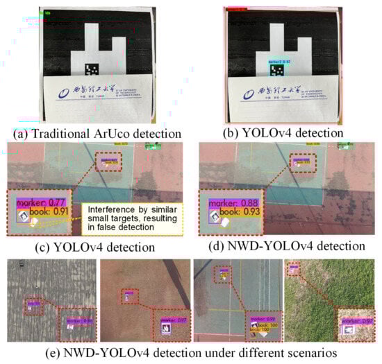
Figure 9.
Landing marker detection results.
To further verify the effectiveness of the proposed detection method, comparison experiments are conducted. Three models including YOLOv4, NWD-YOLOv4, and YOLOv8 are trained on the same small object datasets. The object detection experiments are then performed in the same scenario. The results of quantitative analysis are shown in Table 1.

Table 1.
Results of quantitative analysis of networks.
The performance of YOLO series network is usually evaluated by the detection accuracy (such as mAP@0.5 and mAP@0.5:0.95) and model parameters (such as GFLOPs and params), as shown in Table 1. The AP refers to average precision, which is an indicator calculated by the precision and recall of the network. mAP refers to the mean of the AP value. The mAP@0.5 is the mAP value when the threshold of the NMS evaluation index is 0.5. The mAP@0.5:0.95 indicates the average of the mAP values when the threshold of the evaluation index is 0.5, 0.55, … , 0.95. The GFLOPs refers to the number of floating-point operations and "params" is the total number of parameters that need to be trained in the network model.
As can be seen from Table 1, for the NWD-YOLOv4 method, the values of mAP@0.5 and mAP@0.5:0.95 are 93.70% and 44.72%, respectively, which are 0.73% and 12.36% higher than those of YOLOv4, while the GFLOPs and params of YOLOv4 and NMD-YOLOv4 are the same, that is 6.957G and 6.057M. Hence, it can be concluded that, compared with YOLOv4, the detection accuracy of NWD-YOLOv4 is improved without increasing the amount of computation.
The mAP@0.5 of the YOLOv8 network is 95.1%, which is 1.4% higher than that of NMD-YOLOv4. But the mAP@0.5:0.95 of YOLOv8 is only 24.6%, which is much less than NMD-YOLOv4 with the mAP@0.5:0.95 of 44.72%. This means that, when the NMS threshold is increased, the mAP of YOLOv8 will decrease faster, which is not conducive to the accurate screening of prediction boxes. Meanwhile, GFLOPs and params of YOLOv8 are also much larger than that of NWD-YOLOv4. Hence, compared with YOLOv8, the NWD-YOLOv4 is much faster and with better accuracy at map@0.5:0.95. In summary, the proposed NWD-YOLOv4 has better performance in small target detection tasks.
6.2. Altitude Correction Results Analysis
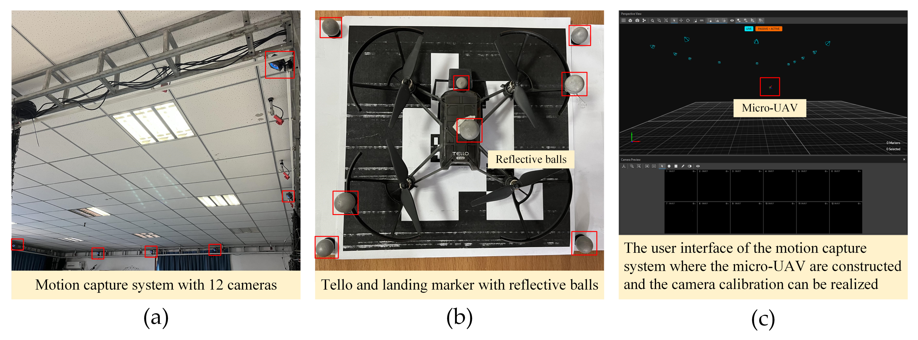
In this subsection, the altitude correction strategy proposed in Section 4.1 is tested. This experiment uses a motion capture system composed of 12 cameras (model type: OptiTrack Prime 13), as shown in Figure 10. The Tello UAV and each landing marker with four reflective balls are placed in the motion capture system workspace. The user host computer software Motive 2.3.1 is used to build the Tello and landing marker rigid body and monitor their motion information in real time in the workspace.
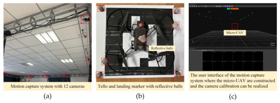
Figure 10.
The motion capture system.
Figure 11a,b present the results of acceleration data of the Tello UAV. The blue curves are all unprocessed data curves, and the red curves represent the filtered data. In Figure 11a, the acceleration signal is obtained from the onboard accelerometer. It can be observed that the unprocessed data have significant noise information due to environmental interference, while the filtered data are smooth by removing partial noise information using the Kalman filter. Figure 11b shows acceleration data by differentiating twice the altitude data estimated by image information. The filtered acceleration data are then used for complementary fusion to obtain a more accurate altitude by the proposed strategy in Section 4.2.
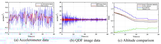
Figure 11.
Altitude fusion results.
In Figure 11c, the comparison result of the altitude data is presented. The black curve represents the altitude estimated from the visual image. The red curve represents the fused altitude obtained using the strategy proposed in Section 4.2. The blue curve is obtained by the motion capture system, mainly used for comparison with the fusion altitude. The green curve represents the error between fusion and real altitude, and it can be observed that the value of this curve gradually tends to zero over time.
6.3. Simulation Test
In this section, the simulation test is conducted to verify the proposed landing guidance strategy based on a simulation platform named Prometheus designed by AMOVLab [33,34]. Both static landing target and moving landing target are considered. The simulation platform is built on the Linux system of Ubuntu 16.04. The ROS-Kinetic and Gazebo simulators are installed. In the simulation, the takeoff point is regarded as the origin of the earth-fixed coordinate system and the landing marker size used is 0.6 m × 0.6 m.
6.3.1. Simulation Result of Landing on Static Target
The landing marker is placed at a position of (1.0, 1.0, 1.0) m statically in the earth-fixed coordinate system. The UAV takes off in the OFFBOARD mode, hovers at the altitude of 5 m. The GPS is first used to guide the UAV to the area near the landing zone. The vision-based landing strategy proposed in this paper is then adopted to guide the UAV once the marker is captured by the UAV camera.
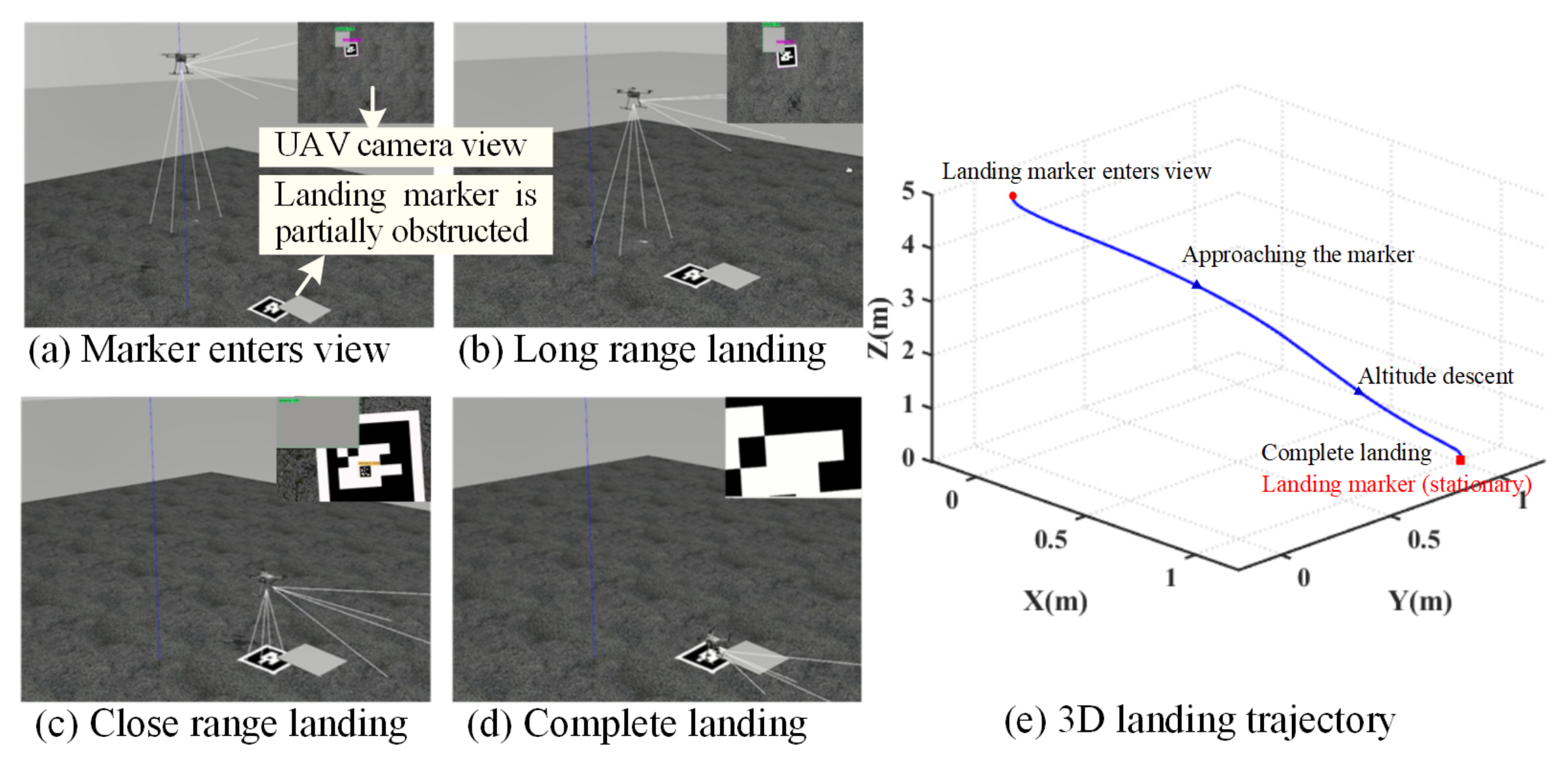
Figure 12 presents the vision-based landing process. The landing marker is continuously partially obstructed. It can be observed that the landing marker can still be detected as shown in the top right corner of Figure 12a. Based on the detected visual information, the UAV is gradually guided to approach the marker as shown in Figure 12b,c. The corresponding 3D landing trajectory of the UAV is presented in Figure 12e.
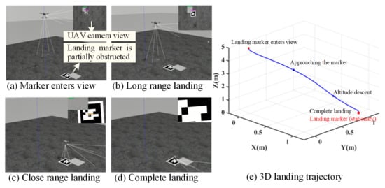
Figure 12.
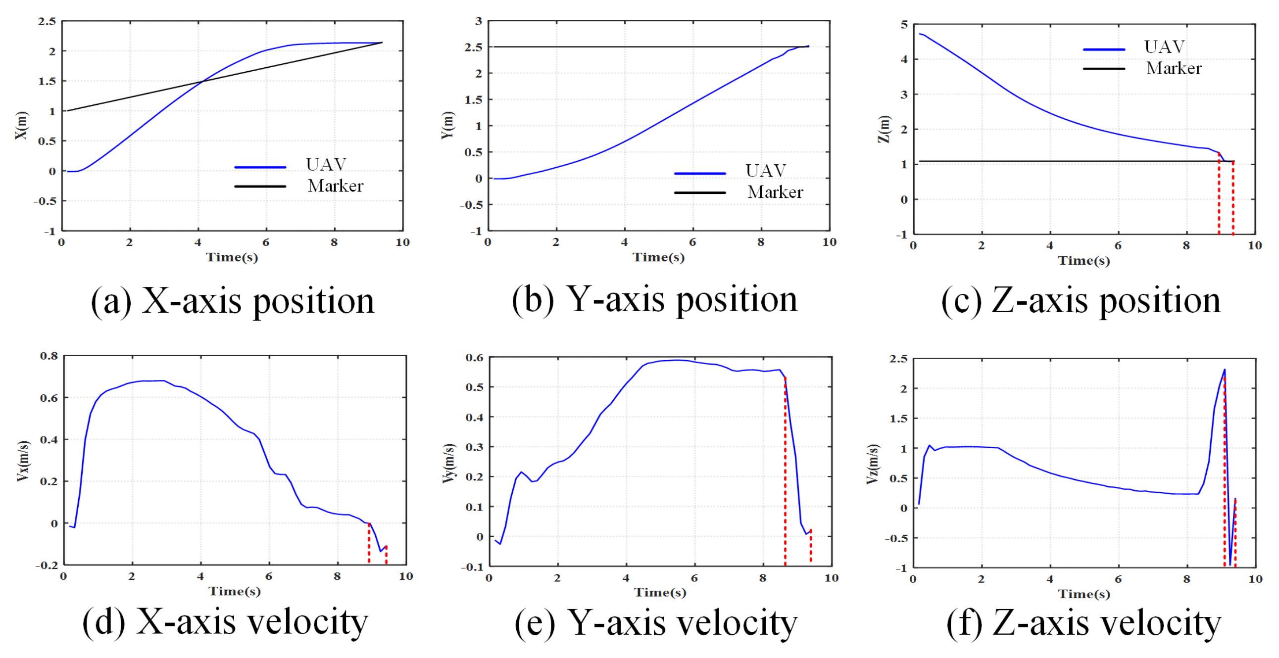
Landing on static target in the simulation platform.
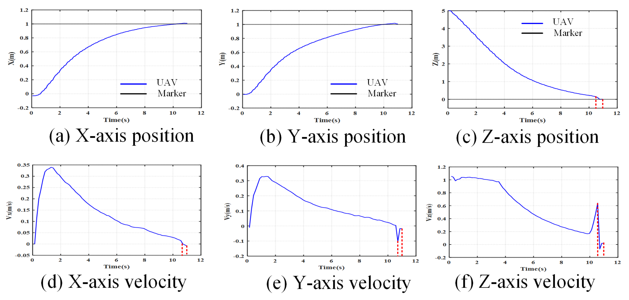
Figure 13 shows the three-axis positions and velocities of the UAV during landing on a static target. In Figure 13c, as shown by the blue curve, the UAV starts landing from the altitude of 5 m. The UAV continuously lowers its altitude to fly closer to the marker denoted by the black curve, with the help of the proposed strategy. The total landing process lasts for 11 s. When the UAV’s altitude decreases to 0.2 m above the marker, only the inner marker is seen by the camera, as shown in Figure 12c. The altitude and vertical velocity show a sudden change at around 10.5 s as illustrated in Figure 13c–f. Meanwhile, the lateral deviation from the landing marker is gradually decreasing as shown in Figure 13a,b. Due to the offset between the center point of inner and outer marker, there is a slight change in horizontal velocity at around 10.5s as shown in Figure 13d,e. After 11 s, the UAV locks and finally lands on the marker. At this point, the position of the UAV is (1.0078, 1.0051, 0) m.
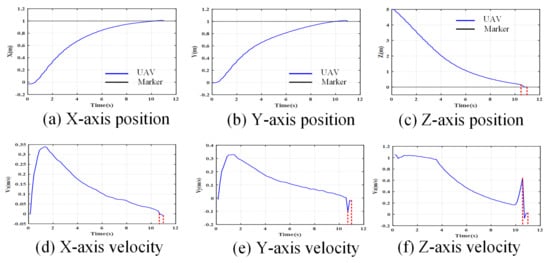
Figure 13.
States of UAV landing on static target in simulation platform.
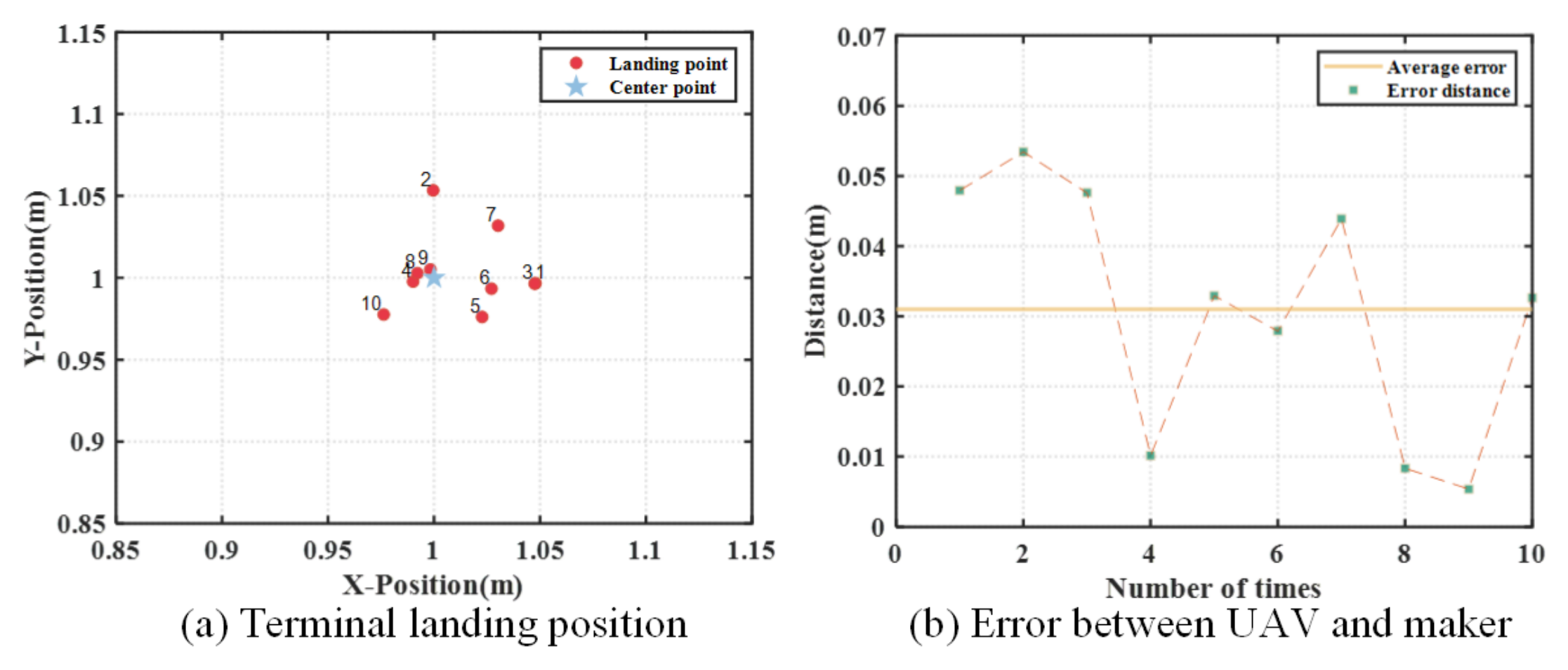
To further verify the accuracy and practicality of proposed landing strategy, 10 simulation cases are conducted. Figure 14a shows the final landing position of the UAV starting from different altitudes ranging from 2.5 m to 3 m to the landing marker, as well as the error distance between the final landing point and the center point of the marker. In Figure 14b, the average distance deviation between the final position of the quad-UAV and the center of marker is 0.031 m. Simulation results demonstrate that the proposed strategy has high accuracy for landing on static targets in the simulation platform.
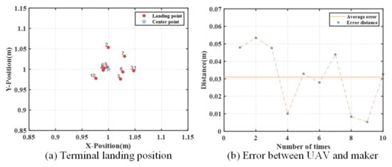
Figure 14.
Landing errors of 10 simulations.
6.3.2. Simulation Result of Landing on Moving Target
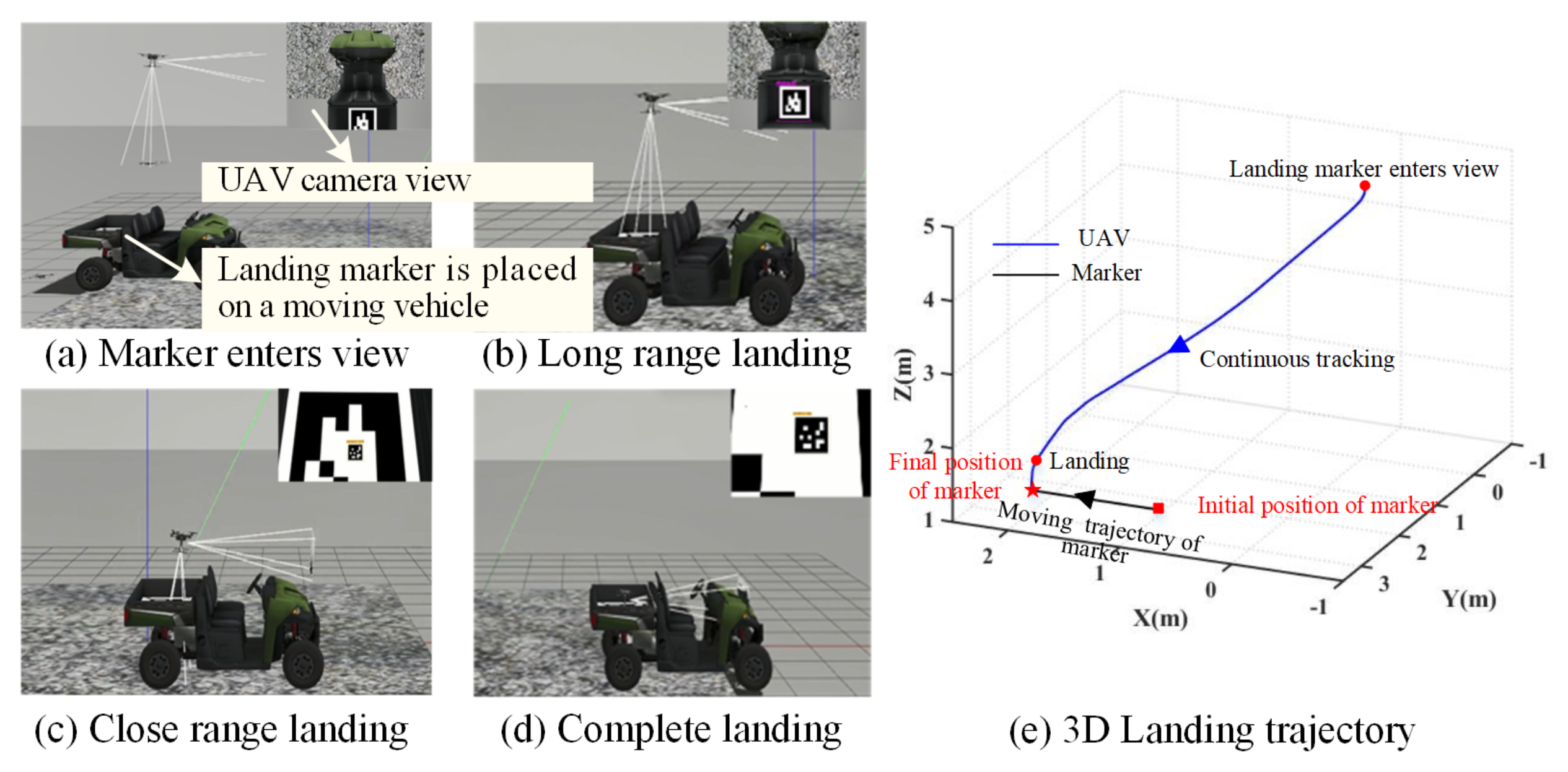
In this subsection, the landing marker is placed on a moving vehicle as shown in Figure 15. The UAV takes off to (0, 0, 5.0) m in the earth-fixed coordinate system and remains in hover. The initial position of the moving vehicle is at (1.0, 2.5) m. The vehicle moves uniformly along the X-axis at a certain speed 0.5 m/s in a straight line, and the Y-axis velocity is maintained at 0 m/s. The carriage altitude of the vehicle is 1.1 m, so the initial position of the landing marker is (1.0, 2.5, 1.1) m. When the UAV’s onboard camera can stably capture the landing marker, the UAV begins to land. Figure 15a–d show the entire process of UAV landing at the moving marker. Figure 15e presents the trajectories of the quad-UAV and the moving marker.
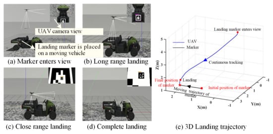
Figure 15.
Landing on moving target in the simulation platform.
Figure 16 shows the position and velocity of the quad-UAV when landing on a moving target. Once the marker is captured by the camera, the UAV starts accelerating along the X-axis. The direction is the same as the moving direction of the vehicle as illustrated by Figure 16a, to ensure that the marker is tracked and it is always in the UAV’s view field. Based on the proposed landing strategy, the altitude of the UAV descends gradually and the lateral position is adjusted as shown in Figure 16a–c. It can be observed that there is a rapid change in horizontal velocity at around 8.5s as shown in Figure 16e. This is because when the distance between UAV and marker reaches view switching distance, the camera can only detect the inner marker, and the center of the inner marker has an offset, causing the speed changes. It also results in a change in vertical velocity as shown in Figure 16f.
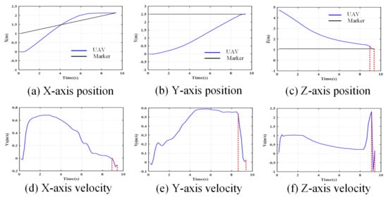
Figure 16.
States of UAV landing on moving target in simulation platform.
The total time for the landing of the UAV is about 9.5 s. Finally, the UAV lands at the position of (2.1398, 2.5211, 1.1) m and the terminal position of the marker is (2.0, 2.5, 1.1) m, as shown by the black curve in Figure 16a,b. The deviation between them on X-axis and Y-axis is 0.1398 m and 0.0211 m, respectively. The above results show that the proposed method has good performance in simulation environments when the landing marker is attached on a moving vehicle with the speed of 0.5 m/s. The moving velocity of the target is low in this simulation. If the moving velocity is faster, the image of the marker is easily lost out of the UAV’s view field. In that case, the recapture strategy will be initiated as discussed in Section 5, which is demonstrated in the next subsection.
6.3.3. Simulation Result in the Case That Marker Is Lost
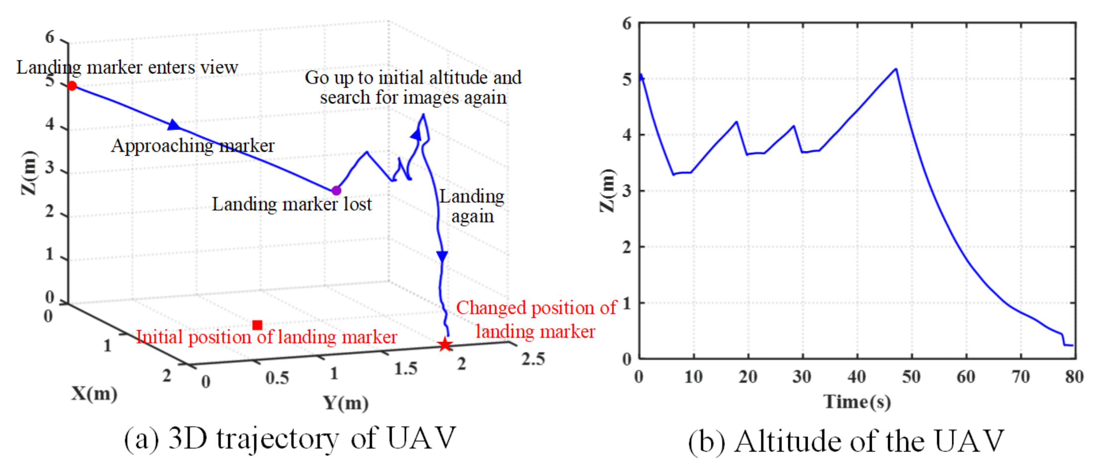
In this subsection, simulation is conducted to verify the proposed recapture strategy in the case that the landing marker is out of the UAV’s field view during the landing process. Figure 17 gives the 3D trajectory and altitude history of the UAV.
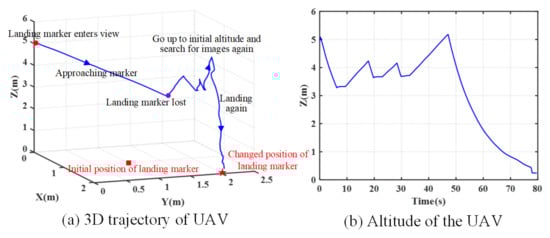
Figure 17.
Landing process in the case that the marker is lost.
The initial landing marker is placed at (1.0, 1.0, 0) m in the earth-fixed coordinate system as denoted by the red square in Figure 17a. When the UAV flies to the altitude of 3.2784 m as labeled by the purple circle in Figure 17a, the landing marker is suddenly moved manually to (2.0, 2.0, 0) m as indicated by the red star in Figure 17a. The marker is out of the UAV’s view field.
From Figure 17b, it can be observed that the UAV begins to descend from an altitude of 5 m. After about 6 s of landing, the marker image is lost. Then, the UAV attempts to search for the marker by changing the lateral position, but does not find it. At about 46 s, it flies up to the initial altitude of 5 m to search the landing marker again. After that, the marker is seen by the camera successfully, the landing guidance strategy works again and directs the UAV to approach the landing marker. The final position of the UAV is (2.0274, 2.0224, 0) m, and the deviation of the UAV on the X-axis and Y-axis is 0.0274 m and 0.0224 m, respectively, with high landing precision.
6.4. Experiment Test
6.4.1. Experiment Platform Description
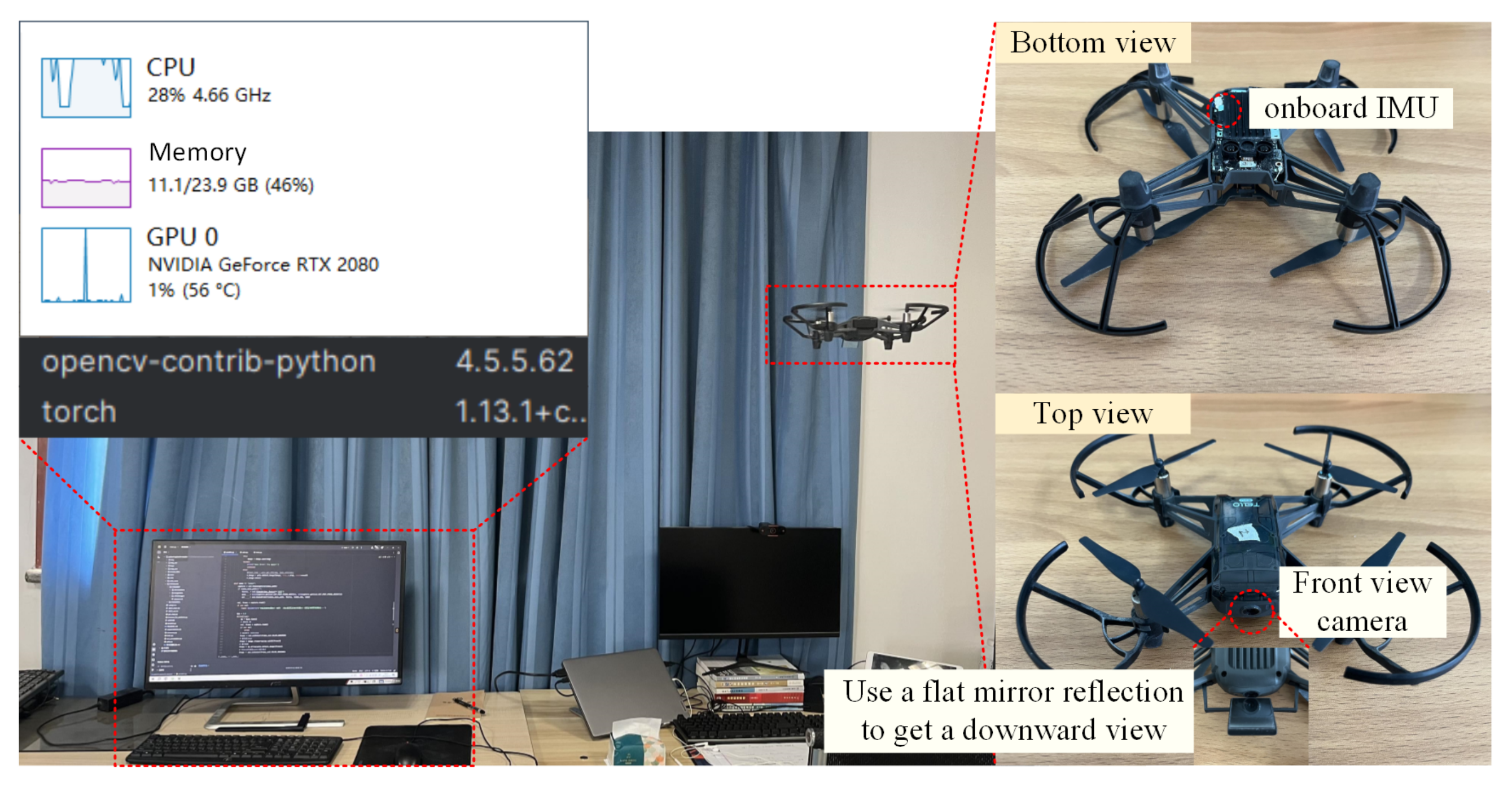
The flight experiments are conducted in this section. The UAV used in the experiments is the DJI Tello UAV with size of 17 cm × 17 cm × 4.1 cm. It is equipped with WiFi communication, an onboard forward-facing camera capable of capturing 720p/30 FPS video, an IMU, and two different modules for estimating altitude including a barometer and a time-of-flight (ToF) module, as shown in Figure 18. The onboard camera’s capability of the small Tello UAV is limited. The camera of Tello UAV is with only forward-looking view. To capture the down-looking view where the landing marker is located, an additional tilted mirror is installed in front of the camera, whose details description can be found in our previous work [34]. The captured video information is then transmitted to the ground station.
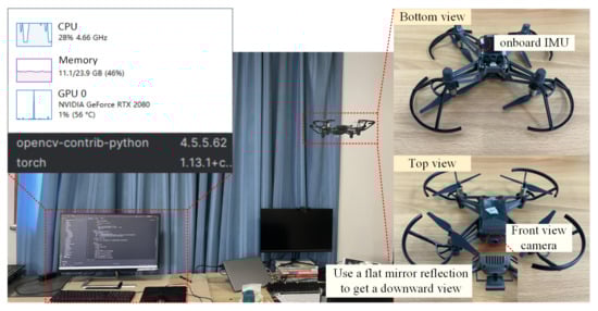
Figure 18.
The flight experiment platform.
The ground station is used to perform marker detection and landing guidance commands calculation as shown in Figure 18. The environment configuration of the ground station is given in Table 2. The size of the marker used in the experiment is 0.205 m × 0.205 m.
Table 2.
Environment configuration of ground station.
6.4.2. Experiment Result of Landing on Static Target
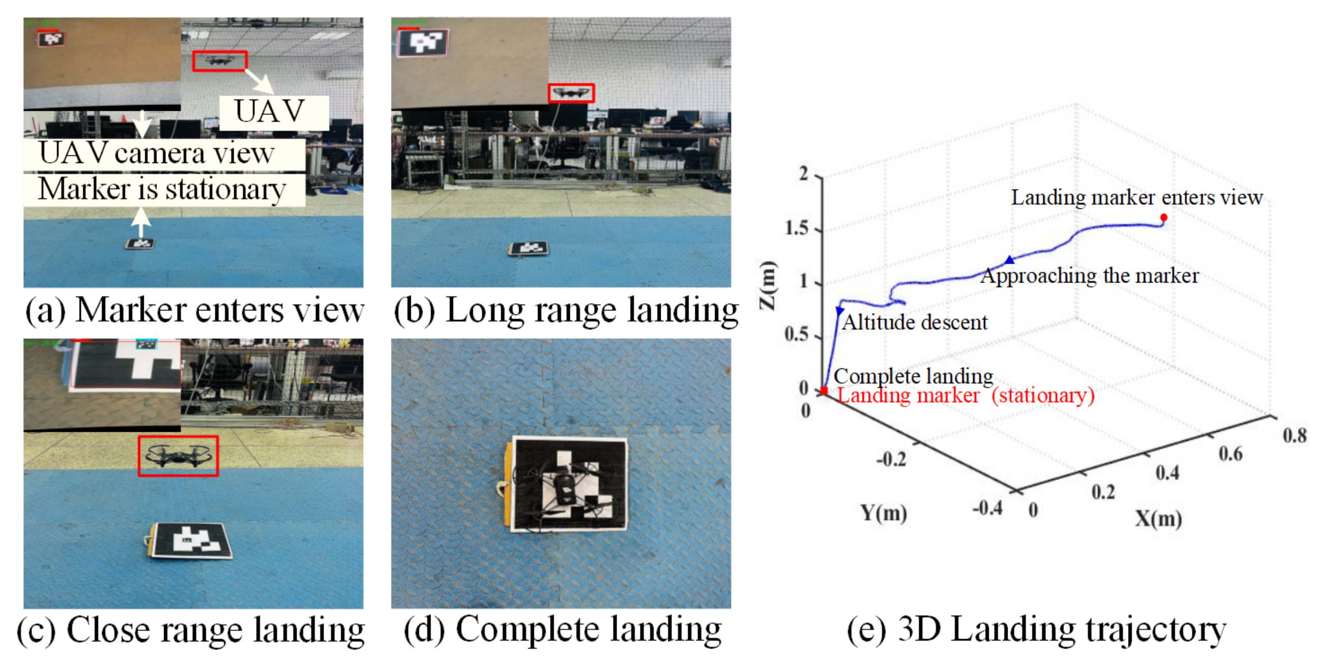
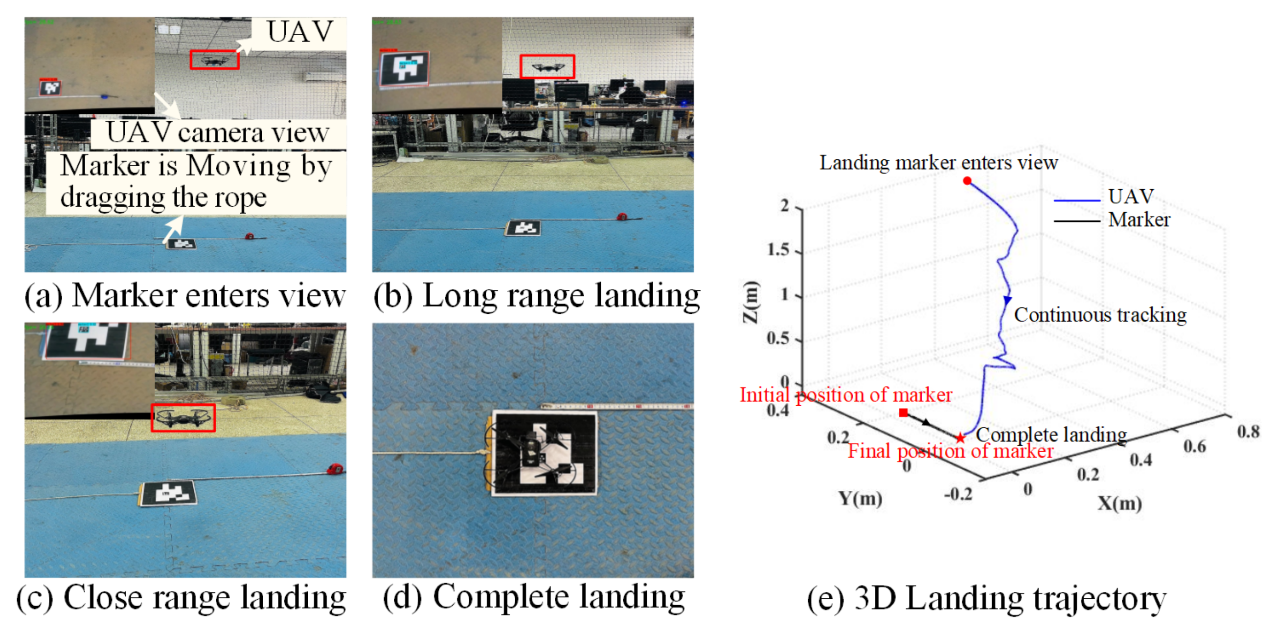
In the experiment, the center point of the marker is chosen as the origin of the earth-fixed coordinate system. The speed limit is set to 0.07 m/s in the X and Y directions and 0.15 m/s in the vertical direction. The PID controller is used to adjust the speed. Figure 19a–d show the static landing experiment process of Tello UAV, and Figure 19e shows the landing trajectory of Tello UAV.

Figure 19.
Landing process on static target in flight experiment.
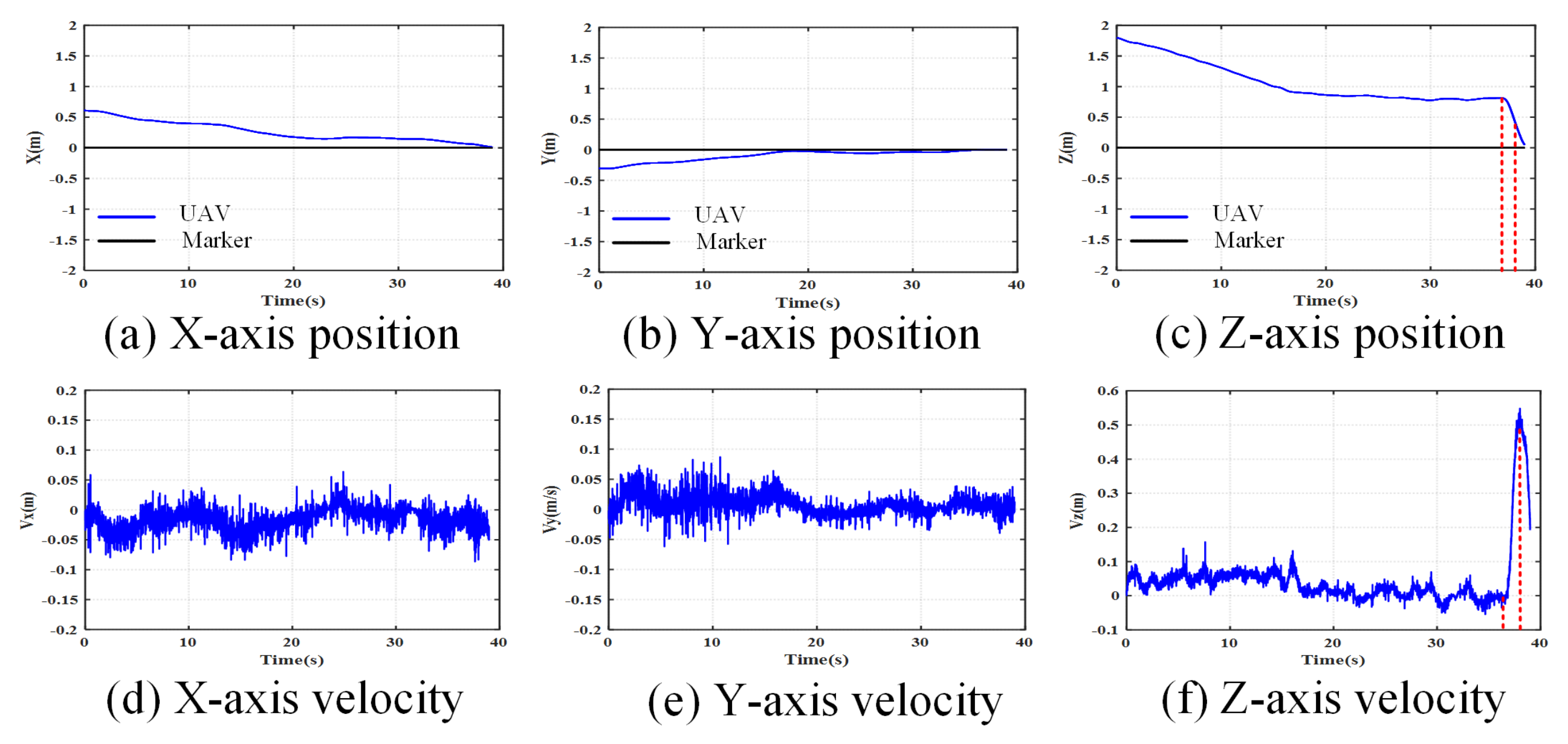
Figure 20 shows the position and velocity in each axis in the static landing process of Tello UAV. The takeoff position of the Tello UAV is (0.6, −0.3, 0) m. In the beginning, the UAV rises to an altitude of 2 m. When part or all the landing markers enter the UAV camera’s view, the UAV begins to approach the landing marker and slowly lowers the altitude based on the proposed landing position adjustment criteria designed in Section 4.2. When the UAV descends to the altitude of 0.8 m, the onboard camera can only observe the inner ArUco which is used for close-ground guidance. It should be noted that, when the altitude of the Tello UAV from the ground decreases to 0.2 m at 38 s, the video stream transmission will also be terminated since the Tello UAV is locked for safety design. Finally, the UAV lands at the current adjusted position under the effect of gravity. The final landing position in the earth-fixed coordinate system is (0.0090, −0.0041, 0) m. The entire process from the appearance of the landing marker in the UAV’s view field to the final landing takes about 39 s.
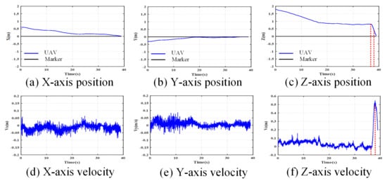
Figure 20.
States of UAV landing on static target in flight experiment.
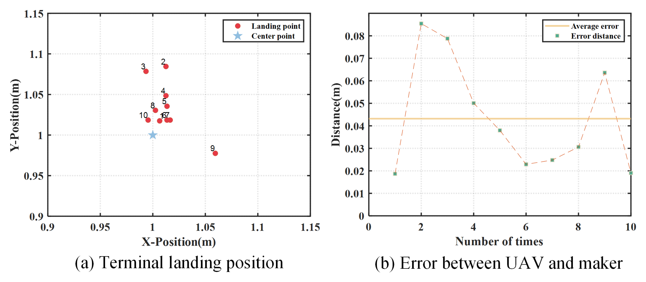
Furthermore, 10 experiments are performed to further verify the proposed strategy. In all 10 cases, the Tello UAV flies to an altitude of 2 m. The deviation between final landing point of UAV and center point of marker are recorded and plotted in Figure 21a. The mean deviation is 0.043 m as given in Figure 21b with good landing precision.
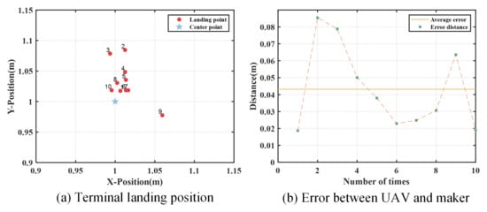
Figure 21.
Landing errors of 10 experiments.
6.4.3. Experiment Result of Landing on Moving Target
In this subsection, landing experiments on moving target are carried out. A rope is used to drag the marker, simulating a slowly and uniformly moving target. Figure 22 shows the landing process and UAV trajectory. Figure 23 shows the position and velocity in various directions in the landing process of the quad-UAV. The marker remains unchanged in both X and Z directions. In the Y direction, the marker is dragged by a rope in a steady slow motion with average speed of 0.015 m/s and maximum speed of 0.18 m/s. In the experiment test, the moving velocity of the target is set slower than that in the simulation test. This is mainly considering the hardware limitation of the Tello UAV platform. The down-view of the UAV is achieved by reflecting the front-view of onboard camera of the Tello UAV through an additional mirror. The field view is affected by the size of the mirror to some extent, which will affect the capture range of the marker during the landing process.
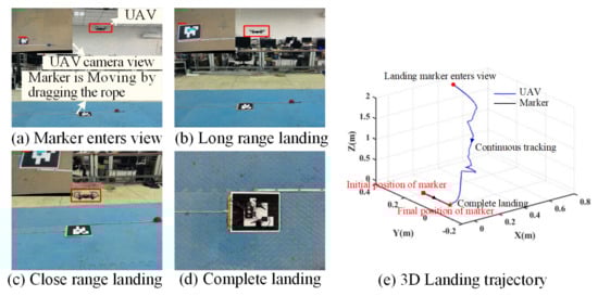
Figure 22.
Landing process on moving target in flight experiment.
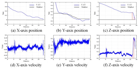
Figure 23.
States of the UAV landing on moving target in flight experiment.
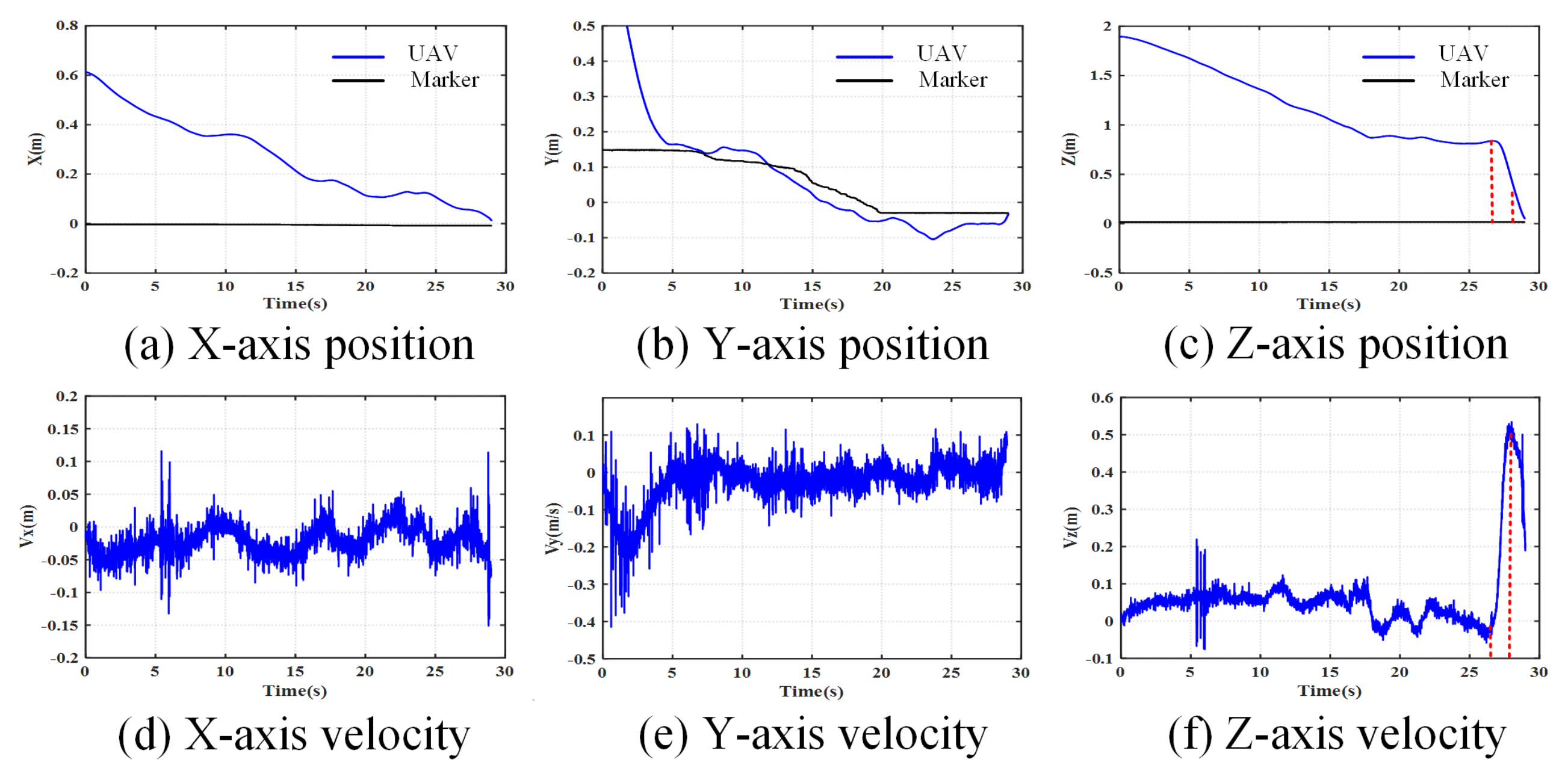
The initial position of the marker is (0, 0.15) m. The UAV takes off at (0.6, 0.8, 2) m in the earth-fixed coordinate system and hovers to search for the landing marker. When the marker appears in the onboard camera’s view field, the UAV begins to continuously track the moving marker, keeping the marker image in the view. The deviation between UAV and marker in X and Y directions is continuously adjusted by the method designed in Section 4.2. Meanwhile, the flight altitude slowly decreases. When the UAV descends to the altitude of 0.8 m, the onboard camera can only observe the inner ArUco which is used for close-ground guidance. When it reaches 0.2 m, the UAV motor turns off and directly lands on the ground. The whole process lasted about 29 s. The final deviation between Tello UAV and marker in X direction is 0.0187 m, and the deviation in the Y direction is 0.0019 m. The experimental result meets the requirements of dynamic landing with satisfactory precision.
7. Conclusions
A vision-based landing guidance method is designed for a quad-UAV. A double-layer ArUco marker is designed to meet the requirement for changes in the field of view of UAV during landing. The YOLOv4 detection algorithm is improved to achieve better accuracy in the case of marker obstruction and small target in high altitude. Subsequently, in response to the issue of deviation in the altitude obtained through visual information, a fusion method of visual and IMU information is proposed, greatly improving the accuracy of altitude estimation. Afterwards, UAV position is adjusted using IBVS for autonomous landing. Considering the possibility of loss of landing marker image during landing, a recapture strategy is designed. Finally, the proposed method is validated through both simulations and flight experiments. In the future work, the UAV hardware platform will be upgraded to achieve rapid landing on fast moving target.
Author Contributions
Conceptualization, L.M. and Y.Z. (Youmin Zhang); Data curation, N.F.; Formal analysis, L.M., S.C. and N.F.; Funding acquisition, L.M.; Methodology, L.M. and X.Z.; Project administration, Y.Z. (Youmin Zhang); Software, S.C., X.Z. and Y.Z. (Yuan Zhang); Supervision, Y.Z. (Youmin Zhang); Validation, L.M., S.C. and Y.Z. (Yuan Zhang); Writing—original draft, L.M.; Writing—review and editing, X.Z., Y.Z. (Youmin Zhang) and N.F. All authors have read and agreed to the published version of the manuscript.
Funding
This research was funded by Aeronautical Science Foundation of China (No. 2024Z0710T6002), National Natural Science Foundation of China (No. 61903297, No. 62373299), China Postdoctoral Science Foundation (No. 2022MD723834), and Key R&D Program of Shaanxi Province (No. 2024GX-YBXM-093). The APC was funded by No. 61903297.
Data Availability Statement
The code of the proposed algorithm can be viewed in https://github.com/Alien828/Autonomous_Landing_Guidance_for_Quad-UAVs_Based_on_Vision_Image_and_Altitude_Estimation.git, accessed on 13 January 2025.
Conflicts of Interest
The authors declare no conflicts of interest.
References
- Duan, H.; Zhao, J.; Deng, Y.; Shi, Y.; Ding, X. Dynamic discrete pigeon-inspired optimization for multi-UAV cooperative search-attack mission planning. IEEE Trans. Aerosp. Electron. Syst. 2021, 57, 706–720. [Google Scholar] [CrossRef]
- Gupta, P.M.; Pairet, E.; Nascimento, T.; Saska, M. Landing a UAV in harsh winds and turbulent open waters. IEEE Robot. Autom. Lett. 2023, 8, 744–751. [Google Scholar] [CrossRef]
- Yuan, Y.; Duan, H.; Zeng, Z. Automatic carrier landing control with external disturbance and input constraint. IEEE Trans. Aerosp. Electron. Syst. 2023, 59, 1426–1438. [Google Scholar] [CrossRef]
- Sawadsitang, S.; Niyato, D.; Tan, P.S.; Wang, P. Joint ground and aerial package delivery services: A stochastic optimization approach. IEEE Trans. Intell. Transp. Syst. 2019, 20, 2241–2254. [Google Scholar] [CrossRef]
- Mu, L.; Xie, G.; Yu, X.; Wang, B.; Zhang, Y. Robust guidance for a reusable launch vehicle in terminal phase. IEEE Trans. Aerosp. Electron. Syst. 2022, 58, 1996–2011. [Google Scholar] [CrossRef]
- Lim, J.; Kim, M.; Yoo, H.; Lee, J. Autonomous Multirotor UAV Search and Landing on Safe Spots Based on Combined Semantic and Depth Information From an Onboard Camera and LiDAR. IEEE/ASME Trans. Mechatron. 2024, 29, 3960–3970. [Google Scholar] [CrossRef]
- Roggi, G.; Gozzini, G.; Invernizzi, D.; Lovera, M. Vision-Based Air-to-Air Autonomous Landing of Underactuated VTOL UAVs. IEEE/ASME Trans. Mechatron. 2024, 29, 2338–2349. [Google Scholar] [CrossRef]
- Zhang, X.; Fang, Y.; Zhang, X.; Jiang, J.; Chen, X. Dynamic image-based output feedback control for visual servoing of multirotors. IEEE Trans. Ind. Inform. 2020, 16, 7624–7636. [Google Scholar] [CrossRef]
- Lin, J.; Wang, Y.; Miao, Z.; Wang, H.; Fierro, R. Robust image-based landing control of a quadrotor on an unpredictable moving vehicle using circle features. IEEE Trans. Autom. Sci. Eng. 2023, 20, 1429–1440. [Google Scholar] [CrossRef]
- Bhargavapuri, M.; Shastry, A.K.; Sinha, H.; Sahoo, S.R.; Kothari, M. Vision-based autonomous tracking and landing of a fully-actuated rotorcraft. Control Eng. Pract. 2019, 89, 113–129. [Google Scholar] [CrossRef]
- Dong, J.; Ren, X.; Han, S.; Luo, S. UAV vision aided INS/odometer integration for land vehicle autonomous navigation. IEEE Trans. Veh. Technol. 2022, 71, 4825–4840. [Google Scholar] [CrossRef]
- Shao, G.; Ma, Y.; Malekian, R.; Yan, X.; Li, Z. A novel cooperative platform design for coupled USV-UAV systems. IEEE Trans. Ind. Inform. 2019, 15, 4913–4922. [Google Scholar] [CrossRef]
- Baca, T.; Stepan, P.; Spurny, V.; Hert, D.; Penicka, R.; Saska, M.; Thomas, J.; Loianno, G.; Kumar, V. Autonomous landing on a moving vehicle with an unmanned aerial vehicle. J. Field Robot. 2019, 36, 874–891. [Google Scholar] [CrossRef]
- Mi, Z.; Yong, Z.; Shuhui, B. Multi-level marker based autonomous landing system for UAVs. Acta Aeronaut. Et Astronaut. Sin. 2018, 39, 213–221. [Google Scholar]
- Cho, G.; Choi, J.; Bae, G.; Oh, H. Autonomous ship deck landing of a quadrotor UAV using feed-forward image-based visual servoing. Aerosp. Sci. Technol. 2022, 130, 107869. [Google Scholar] [CrossRef]
- Fathian, K.; Jin, J.; Wee, S.G.; Lee, D.H.; Kim, Y.G.; Gans, N.R. Camera relative pose estimation for visual servoing using quaternions. Robot. Auton. Syst. 2018, 107, 45–62. [Google Scholar] [CrossRef]
- Lee, D.; Ryan, T.; Kim, H.J. Autonomous landing of a VTOL UAV on a moving platform using image-based visual servoing. In Proceedings of the 2012 IEEE International Conference on Robotics and Automation, Saint Paul, MN, USA, 14–18 May 2012; pp. 971–976. [Google Scholar]
- Lin, J.; Wang, Y.; Miao, Z.; Zhong, H.; Fierro, R. Low-complexity control for vision-based landing of quadrotor UAV on unknown moving platform. IEEE Trans. Ind. Inform. 2022, 18, 5348–5358. [Google Scholar] [CrossRef]
- Cabecinhas, D.; Naldi, R.; Silvestre, C.; Cunha, R.; Marconi, L. Robust landing and sliding maneuver hybrid controller for a quadrotor vehicle. IEEE Trans. Control Syst. Technol. 2016, 24, 400–412. [Google Scholar] [CrossRef]
- Lee, S.; Lee, J.; Lee, S.; Choi, H.; Kim, Y.; Kim, S.; Suk, J. Sliding mode guidance and control for UAV carrier landing. IEEE Trans. Aerosp. Electron. Syst. 2019, 55, 951–966. [Google Scholar] [CrossRef]
- Duan, H.; Yuan, Y.; Zeng, Z. Automatic carrier landing system with fixed time control. IEEE Trans. Aerosp. Electron. Syst. 2022, 58, 3586–3600. [Google Scholar] [CrossRef]
- Vlantis, P.; Marantos, P.; Bechlioulis, C.P.; Kyriakopoulos, K.J. Quadrotor landing on an inclined platform of a moving ground vehicle. In Proceedings of the 2015 IEEE International Conference on Robotics and Automation (ICRA), Seattle, WA, USA, 26–30 May 2015; pp. 2202–2207. [Google Scholar]
- Ji, J.; Yang, T.; Xu, C.; Gao, F. Real-time trajectory planning for aerial perching. In Proceedings of the 2022 IEEE/RSJ International Conference on Intelligent Robots and Systems (IROS), Kyoto, Japan, 23–27 October 2022; pp. 10516–10522. [Google Scholar]
- Gao, Y.; Ji, J.; Wang, Q.; Jin, R.; Lin, Y.; Shang, Z.; Cao, Y.; Shen, S.; Xu, C.; Gao, F. Adaptive tracking and perching for quadrotor in dynamic scenarios. IEEE Trans. Robot. 2024, 40, 499–519. [Google Scholar] [CrossRef]
- Huang, Y.; Zhu, M.; Zheng, Z.; Low, K.H. Homography-based visual servoing for underactuated VTOL UAVs tracking a 6-DOF moving ship. IEEE Trans. Veh. Technol. 2022, 71, 2385–2398. [Google Scholar] [CrossRef]
- Xu, C.; Wang, J.; Yang, W.; Yu, H.; Yu, L.; Xia, G.S. Detecting tiny objects in aerial images: A normalized Wasserstein distance and a new benchmark. ISPRS J. Photogramm. Remote Sens. 2022, 190, 79–93. [Google Scholar] [CrossRef]
- Li, S.; Cui, X.; Guo, L.; Zhang, L.; Chen, X.; Cao, X. Enhanced Automatic Root Recognition and Localization in GPR Images Through a YOLOv4-Based Deep Learning Approach. IEEE Trans. Geosci. Remote Sens. 2022, 60, 1–14. [Google Scholar] [CrossRef]
- Dai, J.S. Euler–Rodrigues formula variations, quaternion conjugation and intrinsic connections. Mech. Mach. Theory 2015, 92, 144–152. [Google Scholar] [CrossRef]
- Hutchinson, S.; Hager, G.D.; Corke, P.I. A tutorial on visual servo control. IEEE Trans. Robot. Autom. 1996, 12, 651–670. [Google Scholar] [CrossRef]
- Mu, L.; Cao, S.; Zhang, Y.; Zhang, X.; Feng, N.; Zhang, Y. Experimental Code. 2024. Available online: https://github.com/Alien828/Autonomous_Landing_Guidance_for_Quad-UAVs_Based_on_Vision_Image_and_Altitude_Estimation.git (accessed on 1 November 2024).
- Mu, L.; Cao, S.; Zhang, Y.; Zhang, X.; Feng, N.; Zhang, Y. Experimental Video. 2024. Available online: https://www.bilibili.com/video/BV1JN4y1H7Fv/ (accessed on 1 November 2024).
- Romero-Ramirez, F.J.; Muñoz-Salinas, R.; Medina-Carnicer, R. Speeded up detection of squared fiducial markers. Image Vis. Comput. 2018, 76, 38–47. [Google Scholar] [CrossRef]
- Mu, L.; Zhang, Y.; Xin, J.; Zhang, Y. Vision-Based Autonomous Landing of a Quadrotor UAV on a Double-Layered Nested Landing Marker. In Proceedings of the International Conference on Guidance, Navigation and Control, Tianjin, China, 5–7 August 2022; Springer: Singapore, 2022; pp. 2995–3004. [Google Scholar]
- Mu, L.; Li, Q.; Wang, B.; Zhang, Y.; Feng, N.; Xue, X.; Sun, W. A Vision-Based Autonomous Landing Guidance Strategy for a Micro-UAV by the Modified Camera View. Drones 2023, 7, 400. [Google Scholar] [CrossRef]

Disclaimer/Publisher’s Note: The statements, opinions and data contained in all publications are solely those of the individual author(s) and contributor(s) and not of MDPI and/or the editor(s). MDPI and/or the editor(s) disclaim responsibility for any injury to people or property resulting from any ideas, methods, instructions or products referred to in the content. |
© 2025 by the authors. Licensee MDPI, Basel, Switzerland. This article is an open access article distributed under the terms and conditions of the Creative Commons Attribution (CC BY) license (https://creativecommons.org/licenses/by/4.0/).